EP2397614A1 - Vorrichtung für hygienische reinigung - Google Patents
Vorrichtung für hygienische reinigung Download PDFInfo
- Publication number
- EP2397614A1 EP2397614A1 EP10741188A EP10741188A EP2397614A1 EP 2397614 A1 EP2397614 A1 EP 2397614A1 EP 10741188 A EP10741188 A EP 10741188A EP 10741188 A EP10741188 A EP 10741188A EP 2397614 A1 EP2397614 A1 EP 2397614A1
- Authority
- EP
- European Patent Office
- Prior art keywords
- water
- water discharge
- pressure
- wash water
- discharge process
- Prior art date
- Legal status (The legal status is an assumption and is not a legal conclusion. Google has not performed a legal analysis and makes no representation as to the accuracy of the status listed.)
- Granted
Links
Images







Classifications
-
- E—FIXED CONSTRUCTIONS
- E03—WATER SUPPLY; SEWERAGE
- E03D—WATER-CLOSETS OR URINALS WITH FLUSHING DEVICES; FLUSHING VALVES THEREFOR
- E03D9/00—Sanitary or other accessories for lavatories ; Devices for cleaning or disinfecting the toilet room or the toilet bowl; Devices for eliminating smells
- E03D9/08—Devices in the bowl producing upwardly-directed sprays; Modifications of the bowl for use with such devices ; Bidets; Combinations of bowls with urinals or bidets; Hot-air or other devices mounted in or on the bowl, urinal or bidet for cleaning or disinfecting
-
- B—PERFORMING OPERATIONS; TRANSPORTING
- B05—SPRAYING OR ATOMISING IN GENERAL; APPLYING FLUENT MATERIALS TO SURFACES, IN GENERAL
- B05B—SPRAYING APPARATUS; ATOMISING APPARATUS; NOZZLES
- B05B1/00—Nozzles, spray heads or other outlets, with or without auxiliary devices such as valves, heating means
- B05B1/02—Nozzles, spray heads or other outlets, with or without auxiliary devices such as valves, heating means designed to produce a jet, spray, or other discharge of particular shape or nature, e.g. in single drops, or having an outlet of particular shape
- B05B1/08—Nozzles, spray heads or other outlets, with or without auxiliary devices such as valves, heating means designed to produce a jet, spray, or other discharge of particular shape or nature, e.g. in single drops, or having an outlet of particular shape of pulsating nature, e.g. delivering liquid in successive separate quantities
- B05B1/083—Nozzles, spray heads or other outlets, with or without auxiliary devices such as valves, heating means designed to produce a jet, spray, or other discharge of particular shape or nature, e.g. in single drops, or having an outlet of particular shape of pulsating nature, e.g. delivering liquid in successive separate quantities the pulsating mechanism comprising movable parts
Definitions
- aspects of this invention relate generally to a sanitary washing device, such as a human body private part washing device for washing the private parts of a human body and a shower device for washing away bodily dirt.
- a sanitary washing device including a pressure generating section for causing a pulsating transition in which a pressure higher than the water discharge pressure obtained from the supply water source is intermittently generated so as to achieve a comfortable washing feeling even with a reduced amount of water used (see Patent Document 1).
- This sanitary washing device disclosed in Patent Document 1 can perform water discharge with increased velocity and repeatedly pulsating flow by causing the pulsating transition of pressure.
- Patent Document 1 has a problem in which there is a tradeoff between the "feeling of stimulation", or the feeling of being strongly washed by wash water with a fast velocity, and the "feeling of volume", or the feeling of being washed by a large amount of wash water. Specifically, to enlarge the water drop, which is formed using velocity difference between discharged waters, it is necessary to decrease the discharged water velocity to ensure overtaking of the subsequent discharged water. However, because of the slowdown in discharged water velocity, the "feeling of stimulation” decreases. Conversely, to enhance the "feeling of stimulation", it is necessary to accelerate the discharged water velocity.
- Patent Document 2 the inventors have investigated such techniques as in Patent Document 2 to realize a high washing feeling establishing compatibility between the feeling of volume and the feeling of stimulation.
- Patent Document 2 discloses a sanitary washing device in which wash water is squirted straight from an orifice portion toward a water discharge port, passes through an air intake portion, and is discharged from the water discharge port (see Claim 1, paragraphs 0006 to 0014, FIG. 2 , etc. in Patent Document 2).
- this sanitary washing device disclosed in Patent Document 2 the surface of wash water is disturbed by the air taken in by the jet due to the air intake effect (ejector effect) to form a thin site and a thick site in the wash water.
- the discharged water causes the "feeling of volume" when impinging on the human body.
- the wash water is squirted straight toward the water discharge port from the orifice portion for causing the ejector effect, it is possible to reduce energy loss due to collision of wash water with the nozzle inner wall surface, that is, to suppress the decrease in the "feeling of stimulation” due to deceleration of wash water.
- the technique is superior in being able to provide a high washing feeling establishing compatibility between the "feeling of volume” and the "feeling of stimulation".
- the invention is a sanitary washing device discharging supplied wash water toward a human body, including:
- wash water discharged from the water discharge port is pressurized so that the amount of overtaking by which the wash water discharged later overtakes the wash water discharged earlier is larger in the first water discharge process than in the second water discharge process to make the first water drop at the predetermined position larger in cross-sectional area than the second water drop, and that the maximum pressure of wash water in the second water discharge process is higher than the maximum pressure of wash water in the first water discharge process to make the velocity of the second water drop at the predetermined position faster than the velocity of the first water drop.
- the adopted technique creates a "first water drop having a large cross-sectional area and a slow velocity", that is, a "large drop” providing the feeling of volume, and a “second water drop having a small cross-sectional area and a fast velocity", that is, a “fast drop” providing the feeling of stimulation. Furthermore, because of the configuration in which the discharged water with the "feeling of stimulation” enhanced and the discharged water with the “feeling of volume” enhanced are alternately discharged from the water discharge port, it is possible to provide a comfortable washing feeling establishing compatibility between the "feeling of volume” and the "feeling of stimulation” while significantly suppressing the amount of water used.
- alternatively discharged used herein is not limited to discharge water in which discharged water by the first water discharge process and discharged water by the second water discharge process are discharged completely in turns, but any water discharge in which discharged water by the first water discharge process or discharged water by the second water discharge process is discharged between the discharged water by the first water discharge process and the discharged water by the second water discharge process is also expressed as alternate.
- a predetermined waiting time is preferably provided after completion of the first water discharge process and before beginning of the second water discharge process so that the second water drop formed in the second water discharge process does not overtake first water drop formed in the first water discharge process at the predetermined position.
- This invention thus configured can prevent the second water drop with a fast velocity, or fast drop, from overtaking the first water drop with a slow velocity, or large drop, before impinging on the human body.
- the "large drop” and the “fast drop” can be caused to impinge on the human body at different timings.
- it is possible to sufficiently provide each of the feeling of volume due to impingement of the "large drop” and the feeling of stimulation due to impingement of the "fast drop” and provide a very favorable washing feeling including both the feeling of stimulation and the feeling of volume even with a small amount of water.
- a time reducer configured to reduce time in which pressure of the wash water drops after the second water discharge process is preferably further included.
- the wash water discharged in the time in which the pressure of wash water drops after the second water discharge process is the so-called wasted water unable to contribute to washing.
- the pressurizing device drops the pressure applied to the wash water to perform the first water discharge process for water discharge at a slow initial velocity, and hence the pressure of wash water drops.
- the wash water discharged during this pressure drop cannot overtake the wash water discharged earlier, and hence cannot contribute to forming any of the first and second water drop. Thus, it is wasteful water unable to contribute to providing a washing feeling.
- a longer waiting time can be provided after the first water discharge process by using the time reducer for reducing the time. This can more reliably prevent the "fast drop” from overtaking the "large drop”.
- the waiting time is preferably provided so that a first time interval from when water discharge by the first water discharge process is discharged from the water discharge port until water discharge by the second water discharge process is discharged from the water discharge port is longer than a second time interval from when the water discharge by the second water discharge process is discharged from the water discharge port until the water discharge by the first water discharge process is discharged from the water discharge port.
- this sanitary washing device by suitably setting the time interval between the water discharge by the first water discharge process and the water discharge by the second water discharge process from the water discharge port, it is possible to prevent extreme difference between the time interval from the impingement of the first water drop on the human body until the impingement of the second water drop on the human body and the time interval from the impingement of the second water drop on the human body until the impingement of the first water drop on the human body, and to reliably provide the continuous feeling of water discharge at the time of impingement on the human body.
- the waiting time is preferably provided so that time interval from when the first water drop formed in the first water discharge process impinges on the human body until the second water drop formed in the second water discharge process impinges on the human body is substantially equal to time interval from when the second water drop impinges on the human body until the first water drop impinges on the human body.
- the pressure of the wash water at beginning of the first water discharge process is preferably made lower than supply water pressure.
- This sanitary washing device can reliably decrease the initial velocity at the beginning of the first water discharge process. This enables the wash water discharged later in the first time span to reliably overtake the wash water discharged earlier. Hence, the cross-sectional area of the first water drop can be further increased.
- the pressure of the wash water at beginning of the second water discharge process is preferably made higher than the pressure of the wash water at beginning of the first water discharge process.
- This sanitary washing device can provide a large difference in velocity between the first water drop by the first water discharge process and the second water drop by the second water discharge process.
- the cross-sectional area of the "large drop” can be further increased by slowing down the initial velocity at the beginning of the first water discharge process to further increase the amount of overtaking by which the wash water discharged later overtakes the wash water discharged earlier.
- the velocity of the "fast drop” can be further accelerated by increasing the initial velocity at the beginning of the second water discharge process.
- increment of pressure of wash water per unit time during the first time span in the first water discharge process is preferably made smaller than increment of pressure of wash water per unit time during the second time span in the second water discharge process.
- the pressure of wash water is increased relatively slowly, and thereby the velocity (initial velocity) of the wash water discharged from the water discharge port increases relatively slowly.
- the amount of overtaking by which the wash water discharged later overtakes the wash water discharged earlier can be further increased.
- the large drop for causing the feeling of volume can be generated in a larger size.
- the cross-sectional area of the first water drop can be further increased by ensuring a sufficient amount of overtaking. Furthermore, in the process for generating the fast drop for causing the feeling of stimulation, although the amount of water is small, a water drop with a relatively fast velocity can be generated. Hence, it is possible to realize highly comfortable washing which reliably establishes compatibility between the feeling of volume and the feeling of stimulation while reducing the total amount of water used.
- the pressurizing device preferably includes a pressurizer configured to apply pressure to the wash water, the pressurizer performs a first pressurization on the wash water in the first water discharge process, and the pressurizer further performs a second pressurization on the wash water in the second water discharge process.
- the timing and cycle for performing the first water discharge process and the second water discharge process can be easily configured.
- the pressurizer preferably includes one pressurizing section, and the one pressurizing section performs the first pressurization and the second pressurization.
- the pressurizer can be downsized as a whole.
- the pressurizer preferably includes a cylinder connected to a supply water conduit, a plunger movably provided inside the cylinder, a check valve provided inside the plunger, and a coil configured to move the plunger forward and backward under control of an exciting voltage, and a check valve is disposed so that the pressure of the wash water increases when position of the plunger is changed to a side of the water discharge port, and that the pressure of the wash water decreases when the position of the plunger is changed to a side opposite to the water discharge port.
- This sanitary washing device is structured so that the operation of the pressurizer is controlled by turning on/off the energization of the coil. Hence, the operation of the pressurizer can be easily configured.
- the pressurizer preferably includes a first pressurizing section and a second pressurizing section, the first pressurizing section performs the first pressurization on the wash water in the first water discharge process, and the second pressurizing section performs the second pressurization on the wash water in the second water discharge process.
- the pressure change in the first water discharge process and the pressure change in the second water discharge process can be made different although the operation itself of each pressurizer has a simple structure.
- the "large drop” and the "fast drop” can be formed more easily.
- the pressurizing device preferably includes: a pressurizer configured to apply pressure to the wash water; and a pressure accumulator provided between the pressurizer and the water discharge port and configured to accumulate the pressure of the wash water, and part of the pressure applied to the wash water by the pressurizer in the second water discharge process is accumulated in the pressure accumulator, and the accumulated pressure is applied to the wash water in the first water discharge process.
- the pressurizer in the second water discharge process for performing water discharge with a faster velocity, the pressurizer is activated to form a second water drop, and part of the pressure is accumulated in the pressure accumulator.
- formation of the first water drop in the first water discharge process can be performed by the accumulated pressure. This can reduce the workload of the pressurizer and improve the durability of the pressurizer.
- the first water discharge process and the second water discharge process can use pressurizing methods suitable for respective water discharge characteristics.
- the pressure accumulator preferably applies the accumulated pressure to the wash water when the pressure of the wash water becomes lower than supply water pressure in the first water discharge process.
- the initial velocity at the beginning of the first water discharge process can be reliably decreased. This can increase the amount of overtaking by which the wash water discharged later overtakes the wash water discharged earlier in the first time span. Thus, the "large drop" can be further enlarged.
- the pressure accumulator is preferably formed as an elastically deformable hose used for a supply water conduit connecting between the pressurizer and the water discharge port.
- the pressure accumulator is an elastically deformable hose, and hence can be implemented in an extremely simple configuration. In addition, this can also lead to downsizing and cost reduction of the sanitary washing device.
- the pressure accumulator in the first water discharge process, preferably applies the pressure to the wash water, and the pressurizer performs the first pressurization.
- both the pressurization by the pressure accumulator and the pressurization by the pressurizer can be applied to wash water. This can facilitate adjusting the rate of increase of the initial velocity in the first water discharge process, and increase the amount of overtaking.
- the pressure accumulator at beginning of water discharge in the first water discharge process, preferably applies the pressure to the wash water, and in second half of the first time span in the first water discharge process, the pressurizer performs the first pressurization.
- time in which the first pressurization in the first water discharge process is performed by the pressurizer is preferably shorter than time in which second pressurization in the second water discharge process is performed.
- the pressurizing time in the first water discharge process can be reduced.
- the durability of the pressurizer can be further improved.
- a time reducer configured to reduce time in which pressure drops after the second water discharge process is preferably included.
- the wash water discharged in the time in which the inner pressure of the washing nozzle drops after the second water discharge process is the so-called wasted water unable to contribute to washing.
- the pressurizing device drops the pressure applied to the wash water to perform the first water discharge process for water discharge at a slow initial velocity, and hence the inner pressure of the washing nozzle drops.
- the wash water discharged during this pressure drop cannot overtake the wash water discharged earlier, or is not overtaken by the wash water discharged later, and hence cannot contribute to forming any of the first and second water drop.
- such water discharge unable to contribute to forming the water drop cannot provide a sufficient washing feeling to the human body. Thus, it is wasteful water unable to contribute to providing a washing feeling.
- a longer waiting time can be provided after the first water discharge process by using the time reducer for reducing the time. This can more reliably prevent the "fast drop” from overtaking the "large drop”.
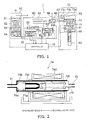
- FIG. 1 is a block diagram of the schematic configuration of a sanitary washing device according to a first embodiment of the invention, focusing on its water channel system.
- the water channel system of the sanitary washing device 1 includes a water inlet side valve unit 50 supplied with water from a supply source (not shown) external to the casing of the sanitary washing device 1, a heat exchange unit 60, and a pulsation generating unit (pressurizing device) 70. That is, the water inlet side valve unit 50, the heat exchange unit 60, and the pulsation generating unit 70 are provided in the water channel system of the sanitary washing device 1 sequentially from the side of the supply source (not shown) external to the casing of the sanitary washing device 1.
- Wash water imparted with pulsation by the pulsation generating unit 70 is guided from the pulsation generating unit 70 to a washing nozzle 82, and discharged from the nozzle 82.
- These units are each housed in the casing of the sanitary washing device 1.
- a solenoid valve 53, an incoming water temperature sensor 62a, a heater 61, an outgoing water temperature sensor 62b, a float switch 63, a pulsation generating device (pressurizer) 74, a flow rate regulating/flow channel switching valve 81, the washing nozzle 82, and control buttons (not shown) are connected to a controller 10.
- the control buttons include a washing button for selecting one of the washing modes of "bottom hard wash” with a strong feeling of stimulation, "bottom soft wash” (hereinafter referred to as “gentle wash”), and "bidet wash", a water strength change button for changing the water strength of wash water, a temperature adjustment button by which the temperature of wash water can be selected, and a stop button for stopping washing.
- These units are each connected by a supply water conduit across the pulsation generating unit 70. More specifically, the water inlet side valve unit 50 and the heat exchange unit 60 are connected by a supply water conduit 55.
- the water inlet side valve unit 50 is directly supplied with wash water (e.g., tap water) from a supply water source (e.g., water pipe). Dust and the like in this wash water guided to the water inlet side valve unit 50 are trapped by a strainer 51 of the water inlet side valve unit 50, and the wash water flows into a check valve 52.
- the conduit is opened by the solenoid valve 53, the wash water flows into a pressure regulator valve 54.
- the pressure regulated to a predetermined pressure e.g., a supply water pressure of 0.110 MPa
- the flow rate of inflow wash water under such pressure regulation is set to approximately 200-600 cc/min.
- the pipe from a flush water tank (not shown) storing flush water for flushing the toilet bowl can be branched to the water inlet side valve unit 50.
- the heat exchange unit 60 downstream of the aforementioned water inlet side valve unit 50 includes a heat exchanger 62 with the heater 61 incorporated therein. While this heat exchange unit 60 uses the incoming water temperature sensor 62a and the outgoing water temperature sensor 62b to detect the temperature of wash water flowing into the heat exchanger 62 and the temperature of wash water flowing out of the heat exchanger 62, the heat exchange unit 60 uses the detected temperature to control the heating operation of the heater 61 so that the wash water is heated to a preset temperature of wash water. That is, in the heat exchange unit 60, heating by the heater 61 is performed so that the temperature of wash water is set to a predetermined preset temperature.
- the heating operation of the heater 61 is controlled by the controller 10 on the basis of the detected temperature from the incoming water temperature sensor 62a and the detected temperature from the outgoing water temperature sensor 62b so that the temperature of wash water is set to a predetermined preset temperature.
- pulsation means pressure variation caused by the pulsation generating unit, and a device or the like causing pressure variation is referred to as pulsation generating unit.
- the pulsation generating device 74 is synonymous with pressurizer. That is, the pulsation generating device 74 can be referred to as a pressurizer for changing the pressure of wash water discharged from the water discharge port.
- this heat exchange unit 60 includes the float switch 63 for detecting the water level in the heat exchanger 62.
- This float switch 63 is configured so as to output a signal indicating that the water level is equal to or higher than a predetermined water level at which the heater 61 is submerged.
- the controller 10 controls energization of the heater 61 under the situation of monitoring input of this signal. Hence, it is possible to prevent energization of the heater 61 not submerged, that is, the so-called boil-dry of the heater 61.
- the heater 61 of the heat exchange unit 60 is optimally controlled by feedforward control and feedback control combined in the controller 10.
- this heat exchange unit 60 includes a vacuum breaker 64 and a safety valve 65 at the wash water outlet from the heat exchanger 62, that is, at the junction of the heat exchanger with the conduit downstream of the heat exchanger 62.
- the vacuum breaker 64 introduces atmospheric air into the conduit under negative pressure to break wash water in the conduit downstream of the heat exchanger and prevent backflow of wash water from the downstream side of the heat exchanger. That is, the vacuum breaker 64 introduces atmospheric air into the conduit under negative pressure so that wash water in the conduit downstream of the heat exchanger is ejected from the washing nozzle 82.
- the safety valve 65 opens and ejects wash water to a wastewater piping 66, thereby preventing malfunctions such as damage to devices and hose disengagement under abnormal conditions.
- FIG. 2 is a schematic configuration sectional view of the pulsation generating device 74.
- the pulsation generating device referred to herein can also be termed as a pressurizer for causing pressure variation.
- the pulsation generating device 74 of this embodiment includes one pressurizing section. As shown in FIG. 2 , the pulsation generating device 74 includes a cylinder 74b connected to the supply water conduits 67, 75, a plunger 74c movably provided inside the cylinder 74b, a check valve 74g provided inside the plunger 74c, and a pulsation generating coil 74d for moving the plunger 74c forward and backward under control of an exciting voltage.
- the check valve is disposed so that the pressure of wash water increases when the position of the plunger 74c is changed to the washing nozzle side (downstream side), and that the pressure of wash water decreases when it is changed to the side (upstream side) opposite to the washing nozzle.
- This plunger 74c is moved to the upstream or downstream side by controlling the excitation of the pulsation generating coil 74d. That is, to add pulsation to wash water (to cause pressure variation in wash water), the plunger 74c is moved forward and backward in the axial direction (upstream direction and downstream direction) of the cylinder 74b by controlling the exciting voltage passed in the pulsation generating coil 74d.
- the plunger 74c moves from the original position (plunger original position) as shown to a downstream side 74h by excitation of the pulsation generating coil 74d. Then, when the excitation of the coil is extinguished, it returns to the original position by the biasing force of a return spring 74f.
- a buffer spring 74e buffers the return motion of the plunger 74c.
- the plunger 74c includes the duckbill check valve 74g to prevent backflow to the upstream side. Hence, at the time of motion from the plunger original position to the downstream side, the plunger 74c can pressurize wash water in the cylinder 74b and drive it to the supply water conduit 75.
- the amount of wash water fed to the supply water conduit 75 in response to the motion of the plunger 74c is constant. Subsequently, at the time of return to the original position, wash water flows into the cylinder 74b through the check valve 74g. Thus, at the next time when the plunger 74c moves to the downstream side, a constant amount of wash water is newly fed to the supply water conduit 75.
- the pulsation generating device 74 is supplied with the wash water at the aforementioned supply water pressure through the supply water conduit 67.
- the wash water poured into the cylinder 74b through the check valve 74g during the return of the plunger 74c to the original position is fed to the supply water conduit 75, although the primary pressure is not maintained due to the effect of pressure loss caused by the check valve 74g and drag-in of wash water on the downstream side. That is, the wash water poured into the cylinder 74b through the check valve 74g during the return of the plunger 74c to the original position flows out toward the supply water conduit 75.
- the pressure of wash water flowing out to the supply water conduit 75 is different from the primary pressure (the aforementioned supply water pressure) due to the effect of pressure loss caused by the check valve 74g and drag-in of wash water on the downstream side.
- FIG. 3 is a schematic diagram for illustrating the state of pressure variation of wash water.
- P in supply water pressure
- wash water is fed from the pulsation generating device 74 to the supply water conduit 75, and then to the washing nozzle 82, and discharged toward the human body private parts.
- the water hammer reduction accumulator 73 includes a housing 73a, a damper chamber 73b in the housing, and a damper 73c placed in this damper chamber.
- the water hammer reduction accumulator 73 thus configured reduces, by the action of the damper 73c, water hammer applied to the supply water conduit 67 on the upstream side of the pulsation generating unit 70. This can alleviate the effect of water hammer exerted on the wash water temperature distribution in the heat exchanger 62, and stabilize the temperature of wash water.
- the water hammer reduction accumulator 73 is placed close to the pulsation generating device 74 or placed integrally with the device 74 from the viewpoint of being able to rapidly and effectively avoid the propagation of pulsation generated in the pulsation generating device 74 to the upstream side. That is, it is preferable that the water hammer reduction accumulator 73 be placed close to the pulsation generating device 74 or that the water hammer reduction accumulator 73 be integrated with the pulsation generating device 74. Then, it is possible to rapidly and effectively suppress the propagation of pulsation generated in the pulsation generating device 74 to the upstream side.
- the flow rate regulating/flow channel switching valve 81 is illustrated.
- the washing nozzle 82 is connected to the flow rate regulating/flow channel switching valve 81 through a supply water conduit 86.
- the supply destination of wash water fed from the pulsation generating device 74 is switched among flow channels 83, 84, 85 (see FIG. 4 ) of the washing nozzle 82, and the flow rate thereof is regulated. That is, the flow rate regulating/flow channel switching valve 81 switches the flow channel so that wash water fed from the pulsation generating device 74 is supplied to each of the flow channels 83, 84, 85 provided in the washing nozzle 82. Furthermore, at this time, the flow channel cross-sectional area is adjusted for flow rate regulation.
- FIGS. 4A and 4B show structure views of the washing nozzle.
- a plurality of the washing flow channels 83, 84, 85 located in the washing nozzle 82 communicate with a water discharge port 401 for bottom wash configured to discharge wash water toward the "bottom" (human body private parts) and a water discharge port 402 for bidet wash, each located near the tip of the washing nozzle.
- Wash water vortex chambers 301, 302 are provided upstream of the water discharge ports 401, 402 so that wash water passed through the washing flow channels 83, 85 is swirled and discharged from the water discharge ports as swirling flows.
- the water discharge port 401 for bottom wash configured to discharge wash water toward the "bottom" (human body private parts) and the water discharge port 402 for bidet wash are provided near the tip of the washing nozzle 82.
- the wash water vortex chamber 301 is provided on the upstream side of the water discharge port 401 so as to communicate therewith.
- the wash water vortex chamber 302 is provided on the upstream side of the water discharge port 402 so as to communicate therewith.
- the washing flow channel 83 is connected tangentially to the wash water vortex chamber 302 shaped like a cylinder.
- the washing flow channel 85 is connected tangentially to the wash water vortex chamber 301 shaped like a cylinder.
- the washing flow channel 84 is connected to the wash water vortex chamber 301 toward its axial center.
- the wash water passed in the tangential direction swirls along the inner wall of the wash water vortex chamber 301, 302, and the swirled wash water is discharged from the water discharge port 401, 402 as a swirling flow.
- the washing flow channel 84 communicates with the upper side of the wash water vortex chamber 301 and communicates with the water discharge port 401. That is, the washing flow channel 83 is connected to the lower portion of the wash water vortex chamber 302. The washing flow channel 84 is connected to the upper portion of the wash water vortex chamber 301, and the washing flow channel 85 is connected to the lower portion of the wash water vortex chamber 301.
- the diameter of the water discharge port 401, 402 is in the approximate range from ⁇ 0.5 mm to ⁇ 1.8 mm, and an optimal diameter is selected depending on the flow rate. For instance, for a flow rate of 430 ml/min, the diameter of the water discharge port 401 for bottom wash is set to approximately ⁇ 0.9 mm, and the diameter of the water discharge port 402 for bidet wash is set to approximately ⁇ 1.4 mm.
- FIG. 5 is a voltage waveform diagram showing the state of excitation of the pulsation generating coil 74d of the pulsation generating device 74 for generating pulsation at the time of discharging wash water (a schematic diagram for illustrating the voltage waveform applied to the pulsation generating coil 74d)
- FIG. 6 is a timing chart showing the velocity (initial velocity) of wash water immediately after discharge from the water discharge port
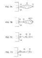
- FIGS. 7A to 7D are views for schematically illustrating the state of wash water discharge from a water discharge port 40.
- the controller 10 To excite the pulsation generating coil 74d to generate pulsation in the pulsation generating device 74, the controller 10 outputs a pulse-like signal. This pulse signal is outputted to a switching transistor (not shown) connected to the pulsation generating coil 74d and configured to turn it on. That is, a switching transistor (not shown) for opening/closing the circuit is connected to the pulsation generating coil 74d. The pulse signal outputted from the controller 10 is inputted to the switching transistor.
- the pulsation generating coil 74d repeats excitation by turning on/off of the switching transistor in accordance with the pulse signal, and periodically reciprocates (moves forward and backward) the plunger 74c as described above. That is, the opening/closing operation (on/off operation) of the switching transistor based on the inputted pulse signal repetitively excites the pulsation generating coil 74d. Furthermore, by repetitively exciting the pulsation generating coil 74d, the plunger 74c is periodically reciprocated (moved forward and backward).
- wash water is supplied from the pulsation generating device 74 to the water discharge port 401 in the state of pulsating flow with the pressure periodically varied up and down, and this pulsating flow of wash water is discharged from each water discharge port.
- FIG. 5 the pulse-like voltage applied to the pulsation generating coil 74d is illustrated in FIG. 5 .
- the pulse-like voltage applied to the pulsation generating coil 74d of the pulsation generating device 74 has a voltage waveform in which two rectangular waves with different on-times are combined during one cycle.
- the velocity change of wash water immediately after discharge from the water discharge port caused by this control is illustrated with reference to the motion of the plunger 74c of the pulsation generating device 74.
- the voltage of the voltage waveform shown in FIG. 5 is applied to the pulsation generating coil 74d of the pulsation generating device 74.
- the pressure decreases to the lowest pressure P1 (see FIG. 3 ).
- the velocity of wash water discharged from the water discharge port 401 also decreases to the lowest velocity region V1.
- the pressure begins to return to the supply water pressure Pin, and the velocity also begins to return to the velocity Vin at the supply water pressure.
- a rectangular wave with on-time T3 shorter than T1 is applied to excite the pulsation generating coil 74d and attract the plunger 74c to the downstream side, thereby pressurizing the wash water again. That is, at this timing of return, a rectangular-wave voltage with on-time T3 shorter than T1 is applied to the pulsation generating coil 74d.
- the wash water is pressurized again by exciting the pulsation generating coil 74d and attracting the plunger 74c to the downstream side.
- the wash water does not rise to the highest pressure P4, but reaches a second peak pressure P2 higher than the supply water pressure.
- the velocity also exhibits a second peak velocity V2 faster than the velocity at the supply water pressure.
- a certain period of time for water discharge near the velocity Vin at the incoming water pressure occurs between the second peak velocity V2 and a velocity V3 at the timing when the plunger is excited again.
- the timing for the voltage waveform applied to the pulsation generating coil 74d is set so that the frequency of pulsation is 50 Hz, T1 is 4.8 msec (milliseconds), T2 is 7 msec, T3 is 1 msec, and T4 is 7.2 msec. That is, the frequency of pulsation is 50 Hz, the on-time T1 is 4.8 msec, the off-time T2 is 7 msec, the on-time T3 is 1 msec, and the off-time T4 is 7.2 msec.
- the frequency and the time span of T1, T2, T3, T4 are not limited thereto.
- the frequency may be any repetition frequency in the dead band frequency region of 5 Hz or more, and the time span of T1, T2, T3, T4 may be set on the basis of the frequency (pulsation cycle MT).
- the dead band frequency is a frequency higher than frequencies which a human being can recognize as change of stimulation, that is, a frequency which a human being cannot perceive as intentional repetition of water discharge.
- FIGS. 7A to 7D are schematic views for illustrating the process in which a pulsating flow of wash water discharged from the hypothetical water discharge port 40 is amplified.
- the relationship between pressure variation and velocity change is illustrated with reference to FIGS. 3 and 6 .
- the pulsation generating device 74 causes the pressure to pulsate, the velocity V also varies and pulsates likewise. That is, in the discharged wash water, when the pressure variation reaches Pmax, the velocity also reaches the maximum velocity Vmax. Thus, the instantaneous velocity varies with time.
- Each of the sites P1, P2, P3, P4, P5 in the pressure waveform of the pulsating flow of wash water in FIG. 3 corresponds to the velocity V1, V2, V3, V4, V5 in FIG. 6 with the same number.
- the wash water discharged with a fast velocity successively unites with the wash water discharged previously with a slow velocity to form a large drop (water discharge group) and impinge on the human body private parts (washing surface).
- V2 can unite with V1 to produce a water discharge group having a large water discharge cross-sectional area before impinging on the human body private parts.
- the overall velocity is slow.
- the wash water discharged with the velocity V2 can overtake the wash water discharged with the velocity V1.
- the wash water discharged with the velocity V2 can unite with the wash water discharged with the velocity V1 to produce a water discharge group (first water drop) having a large water discharge cross-sectional area.
- This wash water (water discharge group having a large water discharge cross-sectional area) is in the state of having a large cross-sectional area of impingement (feeling of volume) when impinging on the human body private parts.
- V4 impinges as a fast water discharge group having a small water discharge cross-sectional area without substantially uniting with V3. That is, in the up-gradient portion of velocity (second water discharge process) between the velocity V3 and the velocity V4 (in the second time span), the overall velocity is fast.
- the wash water discharged with the velocity V4 is less likely to overtake the wash water discharged with the velocity V3. Consequently, before impinging on the human body private parts, the wash water discharged with the velocity V3 and the wash water discharged with the velocity V4 scarcely unite with each other and each result in impinging as a water discharge group (second water drop) having a small water discharge cross-sectional area.
- This wash water (water discharge group having a small water discharge cross-sectional area) is in the state of having a large velocity component in collision energy (feeling of stimulation) when impinging on the human body private parts.
- a sufficient time interval occurs, when V4 is discharged, between the water discharge group generated by V2 and the water discharge group generated by V4. That is, by providing the off-time T4 (waiting time), a sufficient time interval can be provided between the wash water discharged with the velocity V2 and the wash water discharged with the velocity V4.
- the water discharge group generated with the velocity V2 having a large water discharge cross-sectional area, and having a slower velocity than the velocity V4, and the water discharge group generated with the velocity V4, having a small water discharge cross-sectional area, and having a fast velocity, can independently impinge on the human body private parts with different velocities.
- the water discharge group referred to herein is one in which the cross-sectional area cut perpendicularly to the traveling direction of wash water discharged from the water discharge port is larger than the cross-sectional area immediately after discharge from the water discharge port due to overtaking after discharge. That is, the water discharge group refers to one in which the water discharge cross-sectional area (the cross-sectional area cut perpendicularly to the traveling direction of wash water) is larger than the water discharge cross-sectional area immediately after discharge due to overtaking of the wash water discharged subsequently.
- the load when impinging on the human body private parts is larger than that of the discharged water without increase in water discharge cross-sectional area (without formation of the water discharge group).
- FIG. 8 is a timing chart showing the change of load in response to discharged water impinging on the human body private parts in this example. As seen in this figure, during one cycle (pulsation cycle MT), the load increases at two timings. Thus, it turns out that during one cycle, two water discharge groups are formed and impinge independently.
- a water discharge group having a large water discharge cross-sectional area and a slow velocity impinges earlier and a water discharge group having a small water discharge cross-sectional area and a fast velocity impinges later.
- the user can independently feel two water discharge groups different in velocity and size. In this case, the user can feel the feeling of volume by the large and slow water discharge group, and the feeling of stimulation by the small and fast water discharge group.
- the value obtained by integrating the "peak portion" is M ⁇ V, or impact. If this value is sufficiently large, a "feeling of impingement" can be obtained.
- the water discharge group referred to here is one impinging on the human body private parts with a certain impact.
- a slow and large water discharge group with the velocity V2 and a fast and small water discharge group with the velocity V4 each occur at intervals of the pulsation cycle MT.
- the slow and large water discharge group and the fast and small water discharge group occur alternately. That is, water discharge groups occur at intervals of half the pulsation cycle MT.
- pulsation cycle MT even for a long cycle (pulsation cycle MT), a comfortable washing feeling with more continuous feeling can be obtained, and more comfortable washing can be provided even to those who dislike an intermittent feeling.
- the wash waters discharged later with the velocity V5 and the velocity V1 are concatenated with the wash water discharged with the velocity V4.
- the water discharge group is generated in the process in which the wash water discharged with a fast velocity overtakes the wash water discharged with a slow velocity during the time interval from when the wash water is discharged from the water discharge port 40 until impinging on the human body private parts.
- the time for traveling from the water discharge port 40 to the human body private parts is short. For instance, for a velocity of 15 m/sec, the time to reach the human body private parts at 60 mm ahead is 4 msec.
- the time for traveling from the water discharge port 40 to the human body private parts is longer than in the case of the fast velocity region. For instance, for a velocity of 7.5 m/sec, the time to reach the human body private parts is 8 msec.
- the amount of wash water which can overtake is larger when the time to reach the human body private parts is longer. That is, it is possible to efficiently generate a water discharge group having a larger water discharge cross-sectional area when the water discharge group is generated on the lower side of wash water velocity.
- the water discharge group thus generated is a water discharge group having a larger water discharge cross-sectional area
- the water discharge cross-sectional area S is larger than normal.
- a discharged water having a large water discharge cross-sectional area impinges, and there is a washing feeling just like being washed with a high flow rate, or the feeling of volume. That is, by causing a water discharge group having a large water discharge cross-sectional area to impinge, a washing feeling just like being washed with a high flow rate, or the feeling of volume, can be achieved even if the amount of wash water actually used is decreased.
- the water discharge group having a small water discharge cross-sectional area and a fast velocity can scarcely overtake the wash water discharged earlier with the fast velocity V4, and impinges on the human body private parts before forming a water discharge group having a large water discharge cross-sectional area, resulting in a small water discharge cross-sectional area and a poor feeling of volume.
- not overtaking the wash water discharged earlier makes it possible to impinge on the human body private parts without absorption of kinetic energy by the wash water with a slow velocity, hence enabling impingement of water with the feeling of stimulation maintained.
- the impact associated with the feeling of stimulation at this time also increases. That is, although the feeling of volume decreases, the feeling of stimulation can be increased.
- the feeling of volume by developing the feeling of volume with a large and slow water discharge group and developing the feeling of stimulation with a small and fast water discharge group, it is possible to realize highly comfortable washing establishing compatibility between the feeling of volume and the feeling of stimulation.
- the large and slow water discharge group and the small and fast water discharge group each have a sufficient impact.
- pulsation can be felt at intervals of half the pulsation cycle MT.
- This feeling is sufficiently shorter than the feeling which can be distinguished by a human being.
- the feeling of stimulation and the feeling of volume can be realized in combination with the continuous washing feeling.
- FIG. 9 is a timing chart showing the velocity (initial velocity) waveform and the overtaking curve.
- the overtaking curve indicates that wash waters, even different in the timing of water discharge and the velocity of water discharge, impinge simultaneously on the human body private parts at 60 mm ahead as long as they are located on this curve. That is, the overtaking curve is a hypothetical curve for indicating the relationship between velocity and water discharge timing for simultaneous impingement of water on the impinging position at a predetermined distance (which is set to 60 mm in this embodiment).
- the wash water with a slower velocity than this overtaking curve is overtaken by the succeeding wash water with a faster velocity, and they unite with each other and impinge simultaneously on the human body private parts.
- the overtaking curve is superimposed with the reference point set to the velocity V2 (i.e., if the overtaking curve determined with reference to the velocity V2 is superimposed)
- the region of velocity slower than this overtaking curve is entirely overtaken by the wash water having the velocity V2
- a water discharge group with the volume given by the integrated value is generated and impinges on the human body private parts.
- the gradient is more gradual than the overtaking curve, and the slower region "A" (the slope portion on the right side) is very small.
- the overtaking amount is small accordingly, and hence there is no slowdown due to absorption of velocity by a slower velocity. That is, although the amount of wash water of the water discharge group is small, it is less likely that the kinetic energy of the wash water having a fast velocity is absorbed by the wash water having a slow velocity. In other words, a fast water discharge group, although with a small water discharge cross-sectional area, is generated.
- the velocity of the water discharge group is 14 m/sec, and the amount of wash water thereof is 6 microliters. Thus, it impinges on the human body private parts without attenuation of the feeling of stimulation.
- a water discharge group having a large water discharge cross-sectional area because of the large amount of wash water, it is possible to provide the same feeling as in the case of washing with a large amount of water.
- a water discharge group having a small water discharge cross-sectional area and a fast velocity because it impinges on the human body private parts without deceleration, the feeling of stimulation can be felt.
- this water discharge group (the water discharge group having a small water discharge cross-sectional area and a fast velocity) to impinge on the human body private parts with a fast frequency, the feeling of stimulation and the feeling of volume can be felt simultaneously.
- the water discharge cross-sectional area is approximately 12.6 mm 2 for the large water discharge group and 3.8 mm 2 for the small water discharge group. Hence, the water discharge cross-sectional area is different therebetween.
- water discharge groups being relatively different in the water discharge cross-sectional area of the water discharge group generated by overtaking, water discharge groups different in the feeling of stimulation and the feeling of volume are generated and caused to impinge separately, achieving compatibility between the feeling of stimulation and the feeling of volume.
- a water discharge group occurs if the water discharge cross-sectional area is approximately larger than that converted from the diameter of the water discharge port by overtaking of wash water. Furthermore, if water discharge groups being relatively different in the water discharge cross-sectional area of the water discharge group generated by overtaking are generated at the location of impinging on the human body private parts, then it is regarded as generation of different water discharge groups. That is, if water discharge groups being relatively different in water discharge cross-sectional area are generated by overtaking of wash water discharged later until impinging on the human body private parts, then it is regarded as generation of different water discharge groups.
- the feeling of stimulation and the feeling of volume can be produced simultaneously by causing each water discharge group to impinge at least once in the dead band frequency region of 5 Hz or more. That is, the pulsation frequency only needs to be 5 Hz or more.
- washing feeling in this embodiment is illustrated.
- the inventors thought that the washing feeling is represented by the feeling of stimulation and the feeling of volume, which depend on the impact M ⁇ V of discharged water.
- the feeling of stimulation is a feeling in which stimulation similar to pain is felt by impingement of a fast discharged water on the human body private parts, and depends on the velocity V.
- the feeling of volume is a feeling in which impingement of a thick water flow is felt by impingement of discharged water having a large water discharge cross-sectional area S (weight M) with a sufficient strength.
- S water discharge cross-sectional area
- the amount of wash water is 500 ml/min or less in hot water generation by instantaneous heat exchangers in the current mainstream. Hence, it is difficult to satisfy all these physical quantities. Thus, generation of the water discharge group has been investigated to satisfy all these physical quantities.
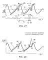
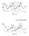
- FIG. 10 shows an example of the velocity waveform of pulsating transition and the shape of generated water discharge groups.
- the fast water discharge group [I] is a water discharge group in which the amount of overtaking is decreased by causing the velocity up-gradient to be more gradual than the gradient of the overtaking curve. Although the velocity is fast, the amount of wash water is small. That is, a water discharge group with the feeling of stimulation but low in the feeling of volume is generated.
- the large water discharge group [II] is a water discharge group gradually collected by overtaking by causing the velocity up-gradient to be close to the gradient of the overtaking curve. In this case, because the velocity is decelerated, the feeling of stimulation is limited. However, a water discharge group with a large amount of wash water and a large impact is generated.
- the scattered water discharge group [III] is a water discharge group in which by causing the velocity up-gradient to be steeper than the gradient of the overtaking curve, overtaking is caused with a large velocity difference between the slow velocity and the fast velocity to scatter the discharged water so that the discharged water with the fast velocity shoots the preceding discharged water with the slow velocity.
- overtaking is caused with a large velocity difference between the slow velocity and the fast velocity to scatter the discharged water so that the discharged water with the fast velocity shoots the preceding discharged water with the slow velocity.
- the apparent water discharge cross-sectional area increases, a water discharge group with a high feeling of volume is generated.
- these different kinds of water discharge groups are each caused to impinge on the human body private parts at least once in the dead band frequency region of approximately 5 Hz or more in which the human perception cannot follow the oscillation based on intentional repetition of water discharge. Then, each discharged water, which independently produces its own physical quantity and feeling, impinges in the dead band frequency region. Hence, it can produce a feeling as a discharged water with all the physical quantities, that is, with the feeling of stimulation and the feeling of volume.
- each of the different water discharge groups independently produces its own physical quantity and feeling, but the different water discharge groups impinge in the dead band frequency region. Hence, it can produce a feeling of water discharge with all the physical quantities, that is, with the feeling of stimulation and the feeling of volume.
- the size, the velocity, and the amount of overtaking of the water discharge group are changed to form water discharge groups with different physical quantities and generate water discharge groups with different feelings. Furthermore, such water discharge groups are caused to independently impinge on the human body private parts in a short period of time, thereby realizing water discharge with a plurality of feelings.
- FIG. 11 shows a schematic view of an example combination of water discharge groups.
- FIG. 11A shows the situation of alternate generation of a "large water discharge group" at time t1 and a "fast water discharge group” at time t2, which are caused to independently impinge on the human body private parts.
- a "large water discharge group" is generated by increasing the amount of overtaking of the discharged water.
- the portion with a fast velocity is attenuated due to overtaking, and the velocity slows down, resulting in a poor feeling of stimulation.
- the size of the water discharge cross-sectional area of the water discharge group increases to a certain area, with the impact increased. Hence, the feeling of volume can be produced.
- These two kinds of water discharge groups are each caused to impinge at least once in the dead band frequency region (5 Hz or more) so that they can be felt as a discharged water with both the feeling of stimulation and the feeling of volume.
- FIG. 11B shows a situation in which a "scattered water discharge group" and a "large water discharge group” are alternately generated.
- a very high feeling of volume is achieved by the "scattered water discharge group”.
- the "large water discharge group” with a large amount of overtaking is generated subsequently.
- a water discharge group with a sufficient impact can be caused to impinge on the human body private parts.
- the feeling of weight of discharged water can be produced.
- the "large water discharge group” impinges on the human body private parts with a faster velocity than the "scattered water discharge group", and hence the discharged water provides more feeling of stimulation than the "scattered water discharge group”.
- the "scattered water discharge group” and the “large water discharge group” can also produce a feeling of discharged water having both the feeling of stimulation and the feeling of volume.
- FIG. 11C shows a situation in which a scattered water discharge group and a fast water discharge group are alternately generated.
- the feeling of stimulation can be produced with the fast water discharge group.
- these water discharge groups may be generated as a combination of the three, and thereby a water discharge with a very high feeling of volume and the feeling of stimulation can be realized.
- the water discharge group is not limited to the configurations illustrated in FIG. 7 , but may have the configurations illustrated in FIGS. 11A to 11C . Furthermore, the water discharge group may be formed by combining the three configurations illustrated in FIGS. 11A to 11C .
- the sequence in which the water discharge groups are formed may be other than those illustrated, and may change every time. Furthermore, the timing at which the water discharge group impinges on the human body private parts does not necessarily need to be regular, but the interval may vary. In this case, for instance, a table of frequencies with different pulsating cycles is prepared in advance, and the frequency may be varied in the dead band frequency region. Furthermore, it may be varied randomly in the dead band frequency region. Moreover, pulsation may be generated sporadically.
- different feelings are generated by different water discharge groups, and a plurality of water discharge groups are caused to impinge in the dead band frequency region so that a different feeling can be generated by each water discharge group. That is, water discharge groups with different physical quantities are formed, and a plurality of water discharge groups are caused to separately impinge on the human body private parts in the dead band frequency region so that a different feeling can be produced by each water discharge group.
- FIG. 12 is a graph for illustrating the state of pressure variation of wash water.
- FIG. 12A corresponds to FIG. 3 , and is an actual measurement of the pressure waveform.
- the pressure of wash water was measured in the wash water vortex chamber 301 communicating with the water discharge port 401.
- the "pressure of wash water” refers to the pressure of wash water in the flow channel (flow channel inner pressure) on the downstream side of the pressurizing device, and is illustratively obtained by measuring the pressure of wash water in the water discharge port 401 or 402, or the wash water vortex chamber 301 or 302 communicating therewith, that is, measuring the pressure of wash water immediately before being discharged from the washing nozzle 82.
- FIG. 12B corresponds to FIG. 5 , and shows the waveform of a pulse-like voltage applied to the pulsation generating coil 74d.
- FIG. 13 is a schematic diagram for illustrating the timing of voltage application, the motion of the plunger, the pressure waveform, and the state of discharged wash water.
- the figure in the upper field shows the state immediately after water discharge
- the figure in the lower field shows the state immediately before impingement of water on the human body private parts.
- a, b, c, d, e in the figure represent wash water discharged under pressure a, b, c, d, e, respectively.
- a high pressure region is formed by active pressurization from the neighborhood of the supply water pressure so that a "water discharge group having a small water discharge cross-sectional area and a fast velocity" is generated in the high pressure region. Because the velocity can be accelerated in the high pressure region, the time to reach the human body private parts can be reduced. This suppresses the situation in which the wash water discharged later overtakes the wash water discharged earlier. This consequently facilitates generating a "water discharge group having a small water discharge cross-sectional area and a fast velocity".
- the overall velocity is fast.
- the wash water b discharged later with the velocity V4 is less likely to overtake the wash water a discharged earlier with the velocity V3. Consequently, the wash water a discharged with the velocity V3 and the wash water b discharged with the velocity V4 scarcely unite with each other and result in impinging on the human body private parts as water discharge groups having a small water discharge cross-sectional area.
- the velocity V3 and the velocity V4 are fast, a water discharge group having a small water discharge cross-sectional area and a fast velocity is generated.
- the voltage is applied to the pulsation generating coil 74d with on-time T3.
- the wash water is pressurized, and the pressure increases.
- the pressure does not increase to the pressure b, but increases to a pressure d, which is a second peak slightly higher than the supply water pressure. That is, as shown in FIG. 12 , when the voltage is applied to the pulsation generating coil 74d with on-time T3, the pressure of wash water does not increase to the pressure P4, but increases to the pressure P2, which is a second peak slightly higher than the supply water pressure.
- the overall velocity is slow. Furthermore, the velocity V2 is faster than the velocity V1.
- the wash water d discharged later with the velocity V2 can overtake the wash water c discharged earlier with the velocity V1. Consequently, the wash water c discharged with the velocity V1 and the wash water d discharged with the velocity V2 unite with each other to produce a water discharge group having a large water discharge cross-sectional area.
- the velocity V1 and the velocity V2 are slower than the velocity V3 and the velocity V4. Hence, a water discharge group having a large water discharge cross-sectional area and a slow velocity is generated.
- the velocity of the wash water d discharged earlier under the pressure d is nearly equal to the velocity of the wash water e discharged later under the pressure e.
- the velocity of the wash water e discharged later cannot overtake and results in individually impinging on the human body private parts.
- the pressure c (pressure P1) formed subsequently can be further decreased. This can facilitate forming the aforementioned "region of pressure lower than the supply water pressure". Furthermore, by active pressurization at the time of return of pressure to the supply water pressure, it is possible to rapidly and stably obtain the pressure around the supply water pressure.
- FIG. 14 shows a voltage waveform applied to the pulsation generating device
- FIG. 15 shows a timing chart of pressure variation of wash water at the nozzle tip caused by the pulsation generating device
- FIG. 16 shows a timing chart of velocity (initial velocity) change of discharged water caused by the pressure variation
- FIG. 17 is a schematic view for illustrating the pulsation generating device and the washing nozzle unit.
- the power supply 76 can apply a plus-side and minus-side voltage.
- the configuration other than the foregoing is nearly the same as that according to the first embodiment. Hence, the detailed description of the same components of the second embodiment as those of the above first embodiment is omitted.
- a voltage waveform including a plus-side voltage and a subsequent minus-side voltage in one cycle is applied to the pulsation generating coil 74d of the pulsation generating device 74.
- the state of water discharge caused by this voltage waveform is illustrated.
- FIG. 16 shows a timing chart of the velocity (initial velocity) of wash water immediately after discharge from the water discharge port, calculated on the basis of the pressure value in FIG. 15 .
- the state of change of the velocity (initial velocity) shown in FIG. 16 is illustrated with reference to the motion of the plunger 74c of the pulsation generating device 74.
- the plunger 74c returns again toward the original position under the biasing force of the buffer spring 74e.
- the pressure normally, the pressure only returns to the supply water pressure. However, by the biasing force of the buffer spring 74e and inflow of wash water, the pressure exceeds the supply water pressure and reaches a second peak pressure P2. Hence, the velocity also exhibits a second peak velocity V2 faster than that at the supply water pressure. Furthermore, a certain period of time for water discharge near the velocity V in at the incoming water pressure occurs between the second peak velocity V2 and the timing when the plunger 74c is excited again (at the time when the velocity is V3).
- the pulsation cycle MT is 20 msec.
- the on-time T1 to 4.8 msec
- the off-time T2 to 1 msec
- the on-time T3 to 1 msec
- the off-time T4 to 13.2 msec.
- the frequency and the time span of T1, T2, T3 are not limited to those illustrated, but can be suitably modified.
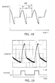
- the applied voltage waveform is not limited to the rectangular wave, but may be a sine waveform as shown in FIG. 18 . In this case, the aforementioned effect can also be achieved by applying voltage halfway through the minus side by phase control.
- the pulsation generating coil 74d is excited by a current flowing therein.
- the plunger 74c is magnetized, and the magnetized plunger 74c is attracted to the downstream side while compressing the return spring 74f.
- the excitation of the pulsation generating coil 74d is extinguished, and the magnetic force of the plunger 74c decreases.
- the plunger 74c returns to the original position by the biasing force of the return spring 74f.
- FIG. 19 shows a temporal variation of the current flowing in the pulsation generating coil 74d in the case where the remanent magnetism is produced.
- the current value becomes 0 V (zero volts)
- the current value does not immediately become 0 A (zero amperes)
- the current flows in a lingering manner (the current value gradually decreases). This is caused by release of residual charge accumulated in the pulsation generating coil 74d. It turns out that this residual charge produces the remanent magnetism and results in producing a force in the opposite direction at the time of return of the plunger 74c.
- FIG. 20 shows the state of the current flowing in the pulsation generating coil 74d at this time.
- the current As seen in FIG. 20 , nearly at the same time as the voltage applied to the pulsation generating coil 74d becomes 0 V, the current also becomes 0 A (zero amperes). Consequently, the effect of the remanent magnetism can be reduced, and the return velocity of the plunger 74c to the original position can be increased.
- reduction of the time interval from the peak velocity V4 to the bottom velocity V1 serves to reduce the region of pressure decrease (velocity decrease), which makes little contribution to washing because no water discharge group is generated. That is, by reducing the time interval from the peak velocity V4 to the bottom velocity V1, it is possible to reduce the pressure-decreasing (velocity-decreasing) region which makes little contribution to washing because no water discharge group is generated.
- the region for reaching from the bottom velocity V1 to the second peak velocity V2 can be formed earlier, and a sufficient free time can be formed between the second peak velocity V2 and the velocity V3 at the next timing for pressurization.
- This also leads to sufficiently expanding the interval available for water discharge groups with different sizes. That is, because the time for reaching from the bottom velocity V1 to the second peak velocity V2 can be reduced, it is possible to expand the interval between the time of the second peak velocity V2 and the time of the velocity V3, or the next timing for pressurization. Thus, it is possible to sufficiently expand the interval in which water discharge groups with different physical quantities are generated. This leads to producing different water discharge groups at uniform time intervals in one cycle. Hence, it is possible to realize comfortable washing with little intermittent feeling even at a frequency lower than the dead band frequency region.
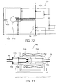
- FIG. 21 is a schematic diagram for illustrating the case where a residual charge consuming circuit is provided.
- FIG. 22 is a schematic circuit diagram for illustrating the residual charge consuming circuit. As shown in FIGS. 21 and 22 , a similar effect can be achieved also by a power supply 77 for applying a voltage to the pulsation generating coil 74d and, additionally, a residual charge consuming circuit 78 which is switched by a switching transistor 79 at the timing of turn-off of the voltage of the pulsation generating coil 74d to consume the residual charge by a capacitor.
- the power supply 77 for applying a voltage to the pulsation generating coil 74d the switching transistor 79 for performing switching at the timing when voltage application to the pulsation generating coil 74d is stopped, and the residual charge consuming circuit 78 including a capacitor 100 for consuming residual charge.
- the switching transistor 79 in the state in which a voltage is applied to the pulsation generating coil 74d (on-state), a circuit current 101 in the figure flows.
- the switching transistor 79 is switched to pass a circuit current 102 so that the capacitor 100 consumes the residual charge.
- a snubber circuit or a bridge circuit may be used to suppress the current value during the off-time of the voltage.
- the method for accelerating the return velocity of the plunger 74c is not limited to the method of reducing the remanent magnetism.
- FIG. 23 shows a variation of the pulsation generating device for accelerating the return velocity of the plunger 74c.
- a pulsation generating device (pressurizer) 74a of this embodiment includes one pressurizing section. As shown in FIG. 23 , a second coil 74k is provided on the upstream side of the pulsation generating coil 74d of the pulsation generating device 74a. That is, the pulsation generating device 74a includes a pulsation generating coil 74d and a second coil 74k provided on the upstream side of the pulsation generating coil 74d. Simple rectangular waves different in phase are applied to the pulsation generating coil 74d and the second coil 74k.
- the method for accelerating the return velocity of the plunger by providing the second coil 74k may be used in combination with the generation of two pulses illustrated in the second embodiment. That is, the method for accelerating the return velocity of the plunger by providing the second coil 74k may be used in combination with the method for accelerating the return velocity of the plunger by using a voltage waveform including a plus-side voltage and a minus-side voltage. This leads to making the large water discharge group even larger and making the fast water discharge group even faster, and it is possible to further increase the feeling of stimulation and the feeling of volume.
- time reducing section for reducing time in which the inner pressure of the washing nozzle drops after the second water discharge process for generating a "water discharge group having a small water discharge cross-sectional area and a fast velocity
- the time reducing section can be the aforementioned one capable of reducing the remanent magnetism, or the aforementioned second coil 74k.
- the time reducing section can be one for reducing time in which the pressure drops after a second pressurization is performed to discharge wash water in a region of pressure at least higher than the supply water pressure for generating a "water discharge group having a large water discharge cross-sectional area and a slow velocity" in the second water discharge process.
- FIG. 24 is a schematic diagram for illustrating the case where a pressure accumulating section is provided.
- the components similar to those described above are labeled with like reference numerals, and the description thereof is omitted.
- the pulsation generating unit 70 of this embodiment includes the pulsation generating device 74 and pressure accumulating sections (pressure accumulators) 75a, 86a. As shown in FIG. 24 , the pulsation generating device 74 and the flow rate regulating/flow channel switching valve 81 are connected by the pressure accumulating section 75a. The flow rate regulating/flow channel switching valve 81 and the washing nozzle 82 are connected by the pressure accumulating section 86a.
- the pressure accumulating sections 75a, 86a can be ones elastically deformed in response to water pressure. For instance, they can be tubes or the like formed from resin, rubber or the like.
- the elastic energy accumulated in the pressure accumulating sections 75a, 86a in response to water pressure can be used to help pressurize wash water.
- pressurization of wash water can be effectively performed.
- pressurization of wash water can be effectively performed.
- FIG. 24 illustrates the case where the pressure accumulating section 75a and the pressure accumulating section 86a are provided, it is possible to provide at least one of them. Furthermore, the elastic energy accumulated in the pressure accumulating sections 75a, 86a can be varied by suitably selecting the spring constant and the like of the material.
- FIG. 25 is a schematic diagram for illustrating the case where a residual charge consuming circuit and a pressure accumulating section are provided.
- the components similar to those described above are labeled with like reference numerals, and the description thereof is omitted.
- the pulsation generating unit 70 of this embodiment includes the pulsation generating device 74 and the pressure accumulating sections 75a, 86a.
- the remanent magnetism can be reduced by the action of the residual charge consuming circuit 78.
- pressurization of wash water can be effectively performed by the action of the pressure accumulating sections 75a, 86a.
- pressurization of wash water can be actively performed by the action of the pulsation generating device 74.
- the details of the action and effect related to the residual charge consuming circuit 78, the pressure accumulating sections 75a, 86a, and the pulsation generating device 74 are similar to those described above, and hence are omitted.
- an air mixing section may be provided so that air can be mixed from the tip portion (the wash water vortex chambers 301, 302 in FIG. 4 ) of the washing nozzle 82.
- the air mixing section can be such that air pressurized by an air pump for forcibly introducing air is mixed from a tube connected to the tip of the washing nozzle 82.
- the timing when the pressurized air is mixed can be adjusted.
- the air pump can be controlled in synchronization with the voltage waveform applied to the pulsation generating device so that air is mixed in the up-gradient range of the slow velocity region.
- the water discharge group is scattered into a wide range. That is, the apparent water discharge cross-sectional area is increased by air and results in a higher feeling of volume.
- the wash water with a fast velocity is discharged without scattering, and impinges on the human body private parts while maintaining the velocity.
- the air mixing section is provided at the tip of the washing nozzle 82, air can be efficiently mixed.
- air is not mixed more than necessity in the fast velocity region, it is also possible to prevent the feeling of stimulation from attenuating due to the damper effect of air.
- the disposing position of the air mixing section is not limited to the tip of the washing nozzle 82, but it may be provided so that air can be mixed into the piping on the upstream side of the washing nozzle 82.
- the air mixing section is not necessarily one capable of forcible mixing, but may be based on natural aspiration. In the case of using natural aspiration, air is mixed into wash water as bubbles. If air is mixed into wash water as bubbles, the volume of the water discharge group can be increased. Consequently, it is possible to establish compatibility between the feeling of stimulation and the feeling of volume in the state of higher feeling of volume.
- a "water discharge group having a large water discharge cross-sectional area and a slow velocity” and a “water discharge group having a small water discharge cross-sectional area and a fast velocity” are generated by varying the amount of overtaking by which the wash water discharged later overtakes the wash water discharged earlier. That is, the controller 10 is configured to perform a first control in a first water discharge process (the process for generating a "water discharge group having a large water discharge cross-sectional area and a slow velocity”) and a second control in a second water discharge process (the process for generating a "water discharge group having a small water discharge cross-sectional area and a fast velocity").
- the water discharge of wash water by the first water discharge process and the water discharge of wash water by the second water discharge process are performed from the same water discharge port.
- the initial velocity at the time of water discharge is made lower than in the second water discharge process so that at a predetermined position from the water discharge port, the amount of overtaking by which the wash water discharged earlier is overtaken by the wash water discharged later is larger than in the second water discharge process.
- the initial velocity at the time of water discharge is made higher than in the first water discharge process so that at the predetermined position from the water discharge port, the amount of overtaking by which the wash water discharged earlier is overtaken by the wash water discharged later is smaller than in the first water discharge process.
- the first water discharge process and the second water discharge process are alternately performed so that the water discharge of wash water by the first water discharge process and the water discharge of wash water by the second water discharge process are alternately discharged from the same water discharge port.
- the feeling of volume can be produced by the "water discharge group having a large water discharge cross-sectional area and a slow velocity".
- the feeling of stimulation can be produced by the "water discharge group having a small water discharge cross-sectional area and a fast velocity". Consequently, even with a limited amount of water, it is possible to realize a highly comfortable sanitary washing device which can produce the feeling of volume and the feeling of stimulation just like being washed with a large amount of water.
- the feeling of discharged water with the feeling of stimulation and the feeling of volume can be produced by causing each of the aforementioned "different water discharge groups" to impinge on the human body private parts at least once in the dead band frequency region of approximately 5 Hz or more which a human being cannot perceive as intentional repetition of water discharge.
- a region of pressure lower than the supply water pressure is formed so that wash water is discharged in the region of pressure lower than the supply water pressure to decrease the initial velocity at the time of water discharge, thereby increasing the amount of overtaking.
- wash water is discharged in the region of pressure higher than the supply water pressure so that the initial velocity at the time of water discharge is higher than in the first water discharge process.
- the pressurizer includes a single pressurizing section
- the controller 10 is configured to perform a first pressurization by the pressurizer in the first water discharge process, and a second pressurization by the pressurizer in the second water discharge process. Then, a "water discharge group having a large water discharge cross-sectional area and a slow velocity" and a "water discharge group having a small water discharge cross-sectional area and a fast velocity" can be generated by the pulsation generating device 74 including one pressurizing section.
- the structure of the pulsation generating device 74 can be further simplified.
- the initial velocity at the time of water discharge can be set to an appropriate value by a simple control configuration of using the pulsation generating device 74 including one pressurizing section to perform the first pressurization in a region of pressure at least lower than the supply water pressure and perform the second pressurization in a region of pressure at least higher than the supply water pressure in the first water discharge process. That is, a sharp velocity difference can be provided to the initial velocity at the time of water discharge between in the water discharge by the first pressurization and in the water discharge by the second pressurization.
- a "predetermined waiting time” is provided between the control for generating a "water discharge group having a large water discharge cross-sectional area and a slow velocity” and the control for generating a "water discharge group having a small water discharge cross-sectional area and a fast velocity”. That is, the off-time T4 is provided.
- a sufficient time interval can be provided between the wash water discharged with the velocity V2 and the wash water discharged with the velocity V4. Consequently, the "different water discharge groups” can be caused to independently impinge on the human body private parts with different velocities without mutual interference. This leads to producing different water discharge groups at uniform time intervals in one cycle.
- a high pressure region is formed by active pressurization from the neighborhood of the supply water pressure so that a "water discharge group having a small water discharge cross-sectional area and a fast velocity" is generated in the high pressure region.
- a "water discharge group having a small water discharge cross-sectional area and a fast velocity" is generated in the high pressure region.
- the pressure P1 formed subsequently is further decreased. This can facilitate forming the aforementioned "region of pressure lower than the supply water pressure". Furthermore, active pressurization is performed at the time of return of pressure to the supply water pressure. This makes it possible to rapidly and stably obtain the pressure around the supply water pressure.
- a pressure accumulating section is further provided between the pulsation generating device 74 and the washing nozzle 82 to accumulate the pressure from wash water.
- the pressure accumulating section accumulates the pressure from wash water in the second water discharge process and applies the accumulated pressure to wash water in the first water discharge process.
- a second pressurization is performed to discharge wash water in a region of pressure at least higher than the supply water pressure, and the pressure from wash water is accumulated in the pressure accumulating section by this second pressurization so that the pressure accumulated in the pressure accumulating section can be applied to wash water in the state in which the pressure of wash water is lower than the supply water pressure.
- the pressure accumulating section can provide wash water with the pressure accumulated when the wash water pressure is lower than the supply water pressure.
- a pressure accumulating section can be formed by suitably selecting the spring constant and the like of the material.
- the pressure accumulating section can be formed as an elastically deformable hose used for a supply water conduit connecting between the pulsation generating device 74 and the washing nozzle 82. Then, the pressure accumulating section can be formed from a simple configuration of an elastically deformable hose.
- the first pressurization by the pressurizer in combination with application of pressure by the pressure accumulating section, the first pressurization by the pressurizer can be performed. Then, the "water discharge group having a large water discharge cross-sectional area and a slow velocity" can be generated by both the pressurization by the pressure accumulating section and the first pressurization by the pressurizer. Hence, a "water discharge group having a large water discharge cross-sectional area and a slow velocity" with a predetermined size can be generated more reliably.
- the first pressurization can be performed in the second half of the process for performing water discharge in the first water discharge process.
- its timing can be shifted from the pressurization by the pressure accumulating section. That is, the pressurization by the pressure accumulating section and the first pressurization can be performed not in parallel but in series.
- the time for which the first pressurization is performed by the pressurizer can be controlled to be shorter than the time for which the second pressurization is performed by the pressurizer. Then, the time of pressurization by the pressurizer in the first water discharge process can be reduced, and hence the device lifetime can be extended by the reduction of control time.
- the waiting time can be terminated when the inner pressure of the washing nozzle 82 becomes the supply water pressure. Then, the second water discharge process performed after the waiting time can be started in the state with the pressure stabilized.
- the pressurization energy in the second water discharge process can be efficiently used to accelerate wash water, and hence the velocity of the "water discharge group having a small water discharge cross-sectional area and a fast velocity" can be reliably increased.
- the waiting time can be established so as to equalize the interval between the impingement of the first water drop formed by the first water discharge process and the impingement of the second water drop formed by the second water discharge process.
- This can equalize the time interval between when the "water discharge group having a large water discharge cross-sectional area and a slow velocity" and the "water discharge group having a small water discharge cross-sectional area and a fast velocity" impinge on the human body private parts, and hence can produce more continuous feeling.
- “different water discharge groups” are generated by using the pulsation generating device 74 including one pressurizing section and controlling the timing of operation thereof. Furthermore, the condition for generating the "different water discharge groups” is controlled so as to be appropriate. This can lead to downsizing, simplification, cost reduction and the like of the sanitary washing device 1.
- FIG. 26 is a schematic configuration sectional view for illustrating a pulsation generating section 90a of the motor-driven reciprocating type.
- the pulsation generating section (pressurizer) 90a has a dual configuration composed of a first pulsation generating section (first pressurizing section) 91a and a second pulsation generating section (second pressurizing section) 92a.
- the first pulsation generating section 91a and the second pulsation generating section 92a include cylinders 910a, 920a, respectively, each including a cylindrical space.
- a piston 910b, 920b is provided in the cylinder 910a, 920a.
- the piston 910b, 920b is equipped with an O-ring 910c, 920c.
- Each space defined by the piston 910b, 920b and the cylinder 910a, 920a constitutes a pressurizing chamber 910d, 920d.
- the pressurizing chamber 910d, 920d is provided with a wash water inlet 910e, 920e so that wash water branched from the supply water conduit 67 flows thereto. That is, the pressurizing chambers 910d, 920d are provided with the wash water inlets 910e, 920e, respectively.
- a conduit, not shown, branched from the supply water conduit 67 is connected to the wash water inlet 910e, 920e so that wash water can be caused to flow from the supply water conduit 67 into the pressurizing chamber 910d, 920d.
- umbrella packings 910f, 920f are provided so as to prevent backflow.
- the umbrella packing 910f, 920f is provided in the portion where the wash water inlet 910e, 920e opens to the pressurizing chamber 910d, 920d so that the wash water poured into the pressurizing chamber 910d, 920d does not flow back to the supply water conduit 67 side.
- wash water outlets 910g, 920g are provided and merged on the way to eject the pressurized wash water. That is, the wash water outlets 910g, 920g are provided in the ceiling portion of the pressurizing chambers 910d, 920d, respectively.
- a piping is connected to each of the wash water outlets 910g, 920g, and each connected piping is connected to the supply water conduit 75 through a bifurcation.
- flows of wash water flowing out of the pressurizing chambers 910d, 920d are merged on the way and ejected to the supply water conduit 75 as pressurized wash water.
- umbrella packings 910h, 920h are used to prevent backflow. That is, the wash water outlet 910g, 920g is provided with the umbrella packing 910h, 920h so that the wash water flowing out to the supply water conduit 75 side does not flow back into the pressurizing chamber 910d, 920d.
- a gear 912 is attached to the rotary shaft of a motor 911 and meshed with a gear 913.
- a crankshaft 914 for driving the piston 910b of the first pulsation generating section 91a and a crankshaft 924 for driving the piston 920b of the second pulsation generating section 92a are attached to different positions of the gear 913.
- the crankshaft 914, 924 is attached to the piston 910b, 920b through a piston holder 915, 925.
- the positions of the crankshafts attached to the gear 913 are different in attachment radius so that the amount of stroke of the piston 910b is different from that of the piston 920b, and they are attached to positions 90° out of phase.
- the stroke of the piston 920b of the second pulsation generating section 92a is adjusted so as to be shorter than the stroke of the piston 910b of the first pulsation generating section 91a and driven 90° out of phase.
- the operation of the pistons 910b, 920b is adjusted in advance by the attachment positions of the crankshafts 914, 914 on the gear 913, it is possible to cause the pulsation generating section 90a to perform a predetermined operation by a simple control of only turning on/off the energization switch of the motor.
- the motor 911 When a user selects and pushes the washing button, the motor 911 is energized to rotate the rotary shaft.
- the pistons 910b, 920b are vertically reciprocated through the gears 912, 913, the crankshaft 914, and the piston holders 915, 925.
- the pressurizing chamber When the pressurizing chamber is filled with wash water, if the piston 910b (920b) moves from the lower dead center (original position) to the upper dead center, the volume of the pressurizing chamber decreases. Hence, the wash water is pressurized and driven toward the supply water conduit 75. Subsequently, in return from the upper dead center to the lower dead center (original position), the pressure in the pressurizing chamber decreases, and the umbrella packing 910f, 920f opens to allow wash water to flow into the pressurizing chamber. Subsequently, at the next time of piston movement, the wash water is pressurized again. This process is successively performed to generate pressure variation, or pulsation.
- the stroke of the piston 920b is adjusted to be approximately half the stroke of the piston 910b and 90° out of phase.
- the cycle is the same.
- the piston 920b has a short stroke, and hence can form a large first water drop by gradual pressurization.
- the piston 910b has a long stroke, and hence can form a region of high pressure by rapidly increasing the pressure. Thus, it can form a second water drop having a fast velocity.
- FIG. 27 is a timing chart showing the pressure variation of wash water and the voltage waveform applied to the pulsation generating device.
- FIG. 28 is a timing chart showing the velocity (initial velocity) of wash water immediately after discharge from the water discharge port.
- the upper row of FIG. 27 is a timing chart illustrating the pressure variation of wash water.
- the lower row of FIG. 27 is a timing chart illustrating the voltage waveform applied to the pulsation generating device.
- the components similar to those described above are labeled with like reference numerals, and the description thereof is omitted.
- the pulse-like voltage applied to the pulsation generating coil 74d of the pulsation generating device 74 has a voltage waveform in which two rectangular waves with different on-times are combined during one cycle.
- the pressure change and velocity change of wash water immediately after discharge from the water discharge port caused by this control are illustrated with reference to the motion of the plunger 74c of the pulsation generating device 74.
- the voltage of the voltage waveform shown in FIG. 27 is applied to the pulsation generating coil 74d of the pulsation generating device 74.
- the pressure begins to return to the supply water pressure Pin, and the velocity also begins to return to the velocity Vin at the supply water pressure.
- a rectangular wave with on-time T3 shorter than T1 is applied to excite the pulsation generating coil 74d and attract the plunger 74c to the downstream side, thereby pressurizing the wash water again. That is, at this timing of return, a rectangular-wave voltage with on-time T3 shorter than T1 is applied to the pulsation generating coil 74d.
- the wash water is pressurized again by exciting the pulsation generating coil 74d and attracting the plunger 74c to the downstream side.
- the wash water does not rise to the highest pressure P4, but reaches a second peak pressure P2 higher than the supply water pressure.
- the velocity also exhibits a second peak velocity V2 faster than the velocity at the supply water pressure.
- a certain period of time for water discharge near the velocity Vin at the incoming water pressure occurs between the second peak velocity V2 and a velocity V3 at the timing when the plunger is excited again.
- the up-gradient of pressure, or the pressure increment of wash water per unit time, in the region indicated by "F1" (between the pressure P1 and the pressure P2) in FIG. 27 is smaller than the up-gradient of pressure, or the pressure increment of wash water per unit time, in the region indicated by "F2" (between the pressure P3 and the pressure P4) in FIG. 27 .
- the pressure increment of wash water per unit time in the region indicated by "F2" in FIG. 27 is larger than the pressure increment of wash water per unit time in the region indicated by "F1” in FIG. 27 .
- the up-gradient of velocity (initial velocity), or the velocity (initial velocity) increment of wash water per unit time, in the region indicated by "G1" (between the velocity V1 and the velocity V2) in FIG. 28 is smaller than the up-gradient of velocity (initial velocity), or the velocity (initial velocity) increment of wash water per unit time, in the region indicated by "G2" (between the velocity V3 and the velocity V4) in FIG. 28 .
- the velocity (initial velocity) increment of wash water per unit time in the region indicated by "G2" in FIG. 28 is larger than the velocity (initial velocity) increment of wash water per unit time in the region indicated by "G1" in FIG. 28 .
- the velocity (initial velocity) of wash water discharged from the water discharge port increases relatively slowly from the velocity V1 to the velocity V2.
- the wash water discharged later e.g., the wash water discharged with the velocity V2
- the large water discharge group for producing the feeling of volume can be generated with a larger size.
- the water discharge cross-sectional area can be further increased by ensuring a sufficient amount of overtaking. Furthermore, in the process for generating a "water discharge group having a small water discharge cross-sectional area and a fast velocity" for producing the feeling of stimulation, although the amount of water is small, it is possible to generate a water discharge group with a relatively fast velocity. Hence, it is possible to realize highly comfortable washing which reliably establishes compatibility between the feeling of volume and the feeling of stimulation while reducing the total amount of water used.
- the waveform of the velocity (initial velocity) of wash water in the region indicated by "G2" in FIG. 28 runs generally along the overtaking curve superimposed with the reference point set to the velocity V2 (i.e., the overtaking curve determined with reference to the velocity V2).
- the pulsation generating device 74 can be combined with the pressure accumulating sections 75a, 86a described above with reference to FIGS. 24 and 25 . Then, the elastic energy accumulated in the pressure accumulating sections 75a, 86a in response to water pressure can be used to help pressurize wash water. In particular, in the low pressure region, pressurization of wash water can be effectively performed. For instance, in the first half of the region indicated by "F1" in FIG. 27 , pressurization of wash water can be effectively performed.
- the pressurizing action of the pressure accumulating sections 75a, 86a by using the pressurizing action of the pressure accumulating sections 75a, 86a, the time T3 of voltage application in the region indicated by "F1" in FIG. 27 can be reduced.
- the other effects of the pressure accumulating sections 75a, 86a are also achieved similarly to the effects of the pressure accumulating sections 75a, 86a described above with reference to FIGS. 24 and 25 .
- FIG. 29 is a timing chart showing the pressure variation of wash water and the voltage waveform applied to the pulsation generating device.
- FIG. 30 is a timing chart showing the velocity (initial velocity) of wash water immediately after discharge from the water discharge port.
- the upper row of FIG. 29 is a timing chart illustrating the pressure variation of wash water.
- the lower row of FIG. 29 is a timing chart illustrating the voltage waveform applied to the pulsation generating device.
- the components similar to those described above are labeled with like reference numerals, and the description thereof is omitted.
- the rectangular-wave voltage is not applied to the pulsation generating coil 74d when the pressure of wash water is about to return from the lowest pressure P1 to the supply water pressure Pin and the velocity is about to return to the velocity Vin at the supply water pressure. That is, the voltage corresponding to the rectangular-wave voltage in the time T3 shown in FIG. 27 is not applied.
- the rest of the operation of the pulsation generating device 74 and the pulse-like voltage applied to the pulsation generating coil 74d of the pulsation generating device 74 are similar to those in the sanitary washing device according to the embodiment described above with reference to FIGS. 27 and 28 .
- no voltage is applied at the timing when the pressure of wash water is about to return from the lowest pressure P1 to the supply water pressure Pin.
- the pressure of wash water becomes comparable to the supply water pressure or reaches a second peak pressure P2 beyond the supply water pressure by the biasing force of the buffer spring 74e and the inflow of wash water.
- the velocity also becomes comparable to that at the supply water pressure or a second peak velocity V2 faster than that at the supply water pressure.
- a certain period of time for water discharge near the velocity V in at the incoming water pressure occurs between the second peak velocity V2 and the timing when the plunger 74c is excited again (at the time when the velocity is V3).
- the up-gradient of pressure, or the pressure increment of wash water per unit time, in the region indicated by "F1" (between the pressure P1 and the pressure P2) in FIG. 29 is smaller than the up-gradient of pressure, or the pressure increment of wash water per unit time, in the region indicated by "F2" (between the pressure P3 and the pressure P4) in FIG. 29 .
- the pressure increment of wash water per unit time in the region indicated by "F2" in FIG. 29 is larger than the pressure increment of wash water per unit time in the region indicated by "F1” in FIG. 29 .
- the up-gradient of velocity (initial velocity), or the velocity (initial velocity) increment of wash water per unit time, in the region indicated by "G1" (between the velocity V1 and the velocity V2) in FIG. 30 is smaller than the up-gradient of velocity (initial velocity), or the velocity (initial velocity) increment of wash water per unit time, in the region indicated by "G2" (between the velocity V3 and the velocity V4) in FIG. 30 .
- the velocity (initial velocity) increment of wash water per unit time in the region indicated by "G2" in FIG. 30 is larger than the velocity (initial velocity) increment of wash water per unit time in the region indicated by "G1" in FIG. 30 .
- the water discharge cross-sectional area can be further increased by ensuring a sufficient amount of overtaking. Furthermore, in the process for generating a "water discharge group having a small water discharge cross-sectional area and a fast velocity" for producing the feeling of stimulation, although the amount of water is small, it is possible to generate a water discharge group with a relatively fast velocity. Hence, it is possible to realize highly comfortable washing which reliably establishes compatibility between the feeling of volume and the feeling of stimulation while reducing the total amount of water used.
- the waveform of the velocity (initial velocity) of wash water in the region indicated by "G2" in FIG. 30 runs generally along the overtaking curve superimposed with the reference point set to the velocity V2 (i.e., the overtaking curve determined with reference to the velocity V2).
- the pulsation generating device 74 can be combined with the pressure accumulating sections 75a, 86a described above with reference to FIGS. 24 and 25 . Then, the elastic energy accumulated in the pressure accumulating sections 75a, 86a in response to water pressure can be used to help pressurize wash water. In particular, in the low pressure region, pressurization of wash water can be effectively performed. For instance, in the first half of the region indicated by "F1" in FIG. 29 , pressurization of wash water can be effectively performed. Furthermore, the other effects of the pressure accumulating sections 75a, 86a are also achieved similarly to the effects of the pressure accumulating sections 75a, 86a described above with reference to FIGS. 24 and 25 .
- This invention can provide a sanitary washing device discharging supplied wash water toward a human body, comprising:
Landscapes
- Health & Medical Sciences (AREA)
- Public Health (AREA)
- Molecular Biology (AREA)
- Epidemiology (AREA)
- Life Sciences & Earth Sciences (AREA)
- Engineering & Computer Science (AREA)
- Hydrology & Water Resources (AREA)
- Water Supply & Treatment (AREA)
- Bidet-Like Cleaning Device And Other Flush Toilet Accessories (AREA)
- Cleaning By Liquid Or Steam (AREA)
Applications Claiming Priority (5)
| Application Number | Priority Date | Filing Date | Title |
|---|---|---|---|
| JP2009029255 | 2009-02-12 | ||
| JP2009071825 | 2009-03-24 | ||
| JP2009144740A JP5196189B2 (ja) | 2008-08-08 | 2009-06-17 | 吐水装置 |
| JP2009144720 | 2009-06-17 | ||
| PCT/JP2010/051723 WO2010092911A1 (ja) | 2009-02-12 | 2010-02-05 | 衛生洗浄装置 |
Publications (3)
| Publication Number | Publication Date |
|---|---|
| EP2397614A1 true EP2397614A1 (de) | 2011-12-21 |
| EP2397614A4 EP2397614A4 (de) | 2014-03-26 |
| EP2397614B1 EP2397614B1 (de) | 2016-09-07 |
Family
ID=43729011
Family Applications (1)
| Application Number | Title | Priority Date | Filing Date |
|---|---|---|---|
| EP10741188.6A Active EP2397614B1 (de) | 2009-02-12 | 2010-02-05 | Vorrichtung für hygienische reinigung |
Country Status (6)
| Country | Link |
|---|---|
| US (1) | US8418278B2 (de) |
| EP (1) | EP2397614B1 (de) |
| KR (1) | KR101232700B1 (de) |
| CN (1) | CN102317547B (de) |
| TW (1) | TWI400384B (de) |
| WO (1) | WO2010092911A1 (de) |
Families Citing this family (16)
| Publication number | Priority date | Publication date | Assignee | Title |
|---|---|---|---|---|
| JP5633267B2 (ja) * | 2009-09-30 | 2014-12-03 | Toto株式会社 | 衛生洗浄装置 |
| CN102359168B (zh) * | 2011-08-18 | 2015-02-04 | 科思利(苏州)工贸有限公司 | 一种智能马桶及其可喷射旋转水流的喷嘴装置 |
| CN105507398B (zh) * | 2014-10-14 | 2017-07-14 | Toto株式会社 | 卫生洗净装置 |
| CN105507399B (zh) * | 2014-10-14 | 2017-06-16 | Toto株式会社 | 卫生洗净装置 |
| CN105421555A (zh) * | 2015-10-10 | 2016-03-23 | 厦门优胜卫厨科技有限公司 | 一种局部冲洗装置 |
| DE102017119610A1 (de) * | 2017-08-26 | 2019-03-21 | Fraunhofer-Gesellschaft zur Förderung der angewandten Forschung e.V. | Verfahren und Vorrichtung zur Erzeugung einer Folge von Strahlabschnitten eines diskontinuierlichen, modifizierten Flüssigkeitsstrahls |
| DE102018130159A1 (de) * | 2018-11-28 | 2020-05-28 | Bayerische Motoren Werke Aktiengesellschaft | Reinigungseinheit |
| CN109602304A (zh) * | 2018-11-30 | 2019-04-12 | 余姚市腾翔电子科技有限公司 | 人体参数解析系统 |
| JP6765644B1 (ja) * | 2019-06-14 | 2020-10-07 | Toto株式会社 | 衛生洗浄装置 |
| JP6979175B2 (ja) * | 2019-07-05 | 2021-12-08 | Toto株式会社 | 衛生洗浄装置 |
| US12037779B2 (en) * | 2020-09-04 | 2024-07-16 | Toto Ltd. | Flush water tank apparatus and flush toilet apparatus provided with the same |
| KR102896026B1 (ko) | 2020-12-28 | 2025-12-04 | 주식회사 콜러노비타 | 온수세정기의 노즐장치 |
| KR20220109130A (ko) | 2021-01-28 | 2022-08-04 | 주식회사 콜러노비타 | 회음부 자극 기능을 가지는 온수세정기 |
| KR20220147930A (ko) | 2021-04-28 | 2022-11-04 | 주식회사 콜러노비타 | 비데의 세정수류 제어방법 |
| CN113577873B (zh) * | 2021-08-24 | 2022-08-12 | 泰能天然气有限公司 | 一种过滤装置 |
| KR20240159160A (ko) | 2023-04-28 | 2024-11-05 | 주식회사 콜러노비타 | 비데의 회음부 마사지를 위한 온열케어모드 제어장치와 그 제어방법 |
Family Cites Families (13)
| Publication number | Priority date | Publication date | Assignee | Title |
|---|---|---|---|---|
| US5390277A (en) * | 1992-03-27 | 1995-02-14 | Andermac, Inc. | Flow through electrical heat controller having asymptotic temperature control arrangement to avoid overshoot |
| US5826282A (en) * | 1994-03-09 | 1998-10-27 | Matsushita Electric Industrial Co., Ltd. | Sanitary cleaning apparatus |
| TW373047B (en) * | 1997-04-02 | 1999-11-01 | Matsushita Electric Industrial Co Ltd | Apparatus for washing human private |
| JP3264274B2 (ja) * | 1999-01-25 | 2002-03-11 | 東陶機器株式会社 | 人体洗浄装置 |
| AU3077500A (en) * | 1999-01-25 | 2000-08-07 | Toto Ltd. | Human body washing device |
| JP2001173068A (ja) * | 1999-12-17 | 2001-06-26 | Taisan Kogyo Kk | 洗滌注液脈動発生装置用電磁ポンプ |
| JP4984363B2 (ja) | 2000-09-07 | 2012-07-25 | Toto株式会社 | 人体局部洗浄ノズルおよびこれを備えた人体局部洗浄装置 |
| JP2003268845A (ja) | 2002-03-13 | 2003-09-25 | Matsushita Electric Ind Co Ltd | 衛生洗浄装置 |
| KR100939144B1 (ko) * | 2002-01-15 | 2010-01-28 | 파나소닉 주식회사 | 위생 세정 장치 |
| JP4084102B2 (ja) | 2002-06-26 | 2008-04-30 | 松下電器産業株式会社 | 衛生洗浄装置 |
| KR101104458B1 (ko) * | 2002-08-29 | 2012-01-12 | 파나소닉 주식회사 | 위생 세정 장치 |
| JP4486317B2 (ja) * | 2003-04-28 | 2010-06-23 | パナソニック株式会社 | ノズル装置およびそれを備えた衛生洗浄装置 |
| CN102076918B (zh) * | 2008-07-03 | 2012-12-26 | 松下电器产业株式会社 | 卫生清洗装置 |
-
2010
- 2010-02-05 WO PCT/JP2010/051723 patent/WO2010092911A1/ja not_active Ceased
- 2010-02-05 KR KR1020117018475A patent/KR101232700B1/ko active Active
- 2010-02-05 CN CN2010800074946A patent/CN102317547B/zh active Active
- 2010-02-05 US US12/922,493 patent/US8418278B2/en active Active
- 2010-02-05 EP EP10741188.6A patent/EP2397614B1/de active Active
- 2010-02-08 TW TW099103853A patent/TWI400384B/zh active
Also Published As
| Publication number | Publication date |
|---|---|
| CN102317547A (zh) | 2012-01-11 |
| TW201035421A (en) | 2010-10-01 |
| CN102317547B (zh) | 2013-12-04 |
| EP2397614A4 (de) | 2014-03-26 |
| TWI400384B (zh) | 2013-07-01 |
| KR101232700B1 (ko) | 2013-02-13 |
| EP2397614B1 (de) | 2016-09-07 |
| US20110061160A1 (en) | 2011-03-17 |
| US8418278B2 (en) | 2013-04-16 |
| KR20110122676A (ko) | 2011-11-10 |
| WO2010092911A1 (ja) | 2010-08-19 |
Similar Documents
| Publication | Publication Date | Title |
|---|---|---|
| EP2397614B1 (de) | Vorrichtung für hygienische reinigung | |
| EP2354338B1 (de) | Sanitärwaschvorrichtung | |
| WO2000043602A1 (en) | Human body washing device | |
| JP3292185B2 (ja) | 人体洗浄装置 | |
| US8667621B2 (en) | Sanitary washing apparatus | |
| JP2007162463A (ja) | 人体洗浄装置 | |
| JP2010222856A (ja) | 人体洗浄装置 | |
| JP4609748B2 (ja) | 人体洗浄装置 | |
| JP5196189B2 (ja) | 吐水装置 | |
| CN102628293B (zh) | 卫生清洗装置 | |
| JP2001090152A (ja) | 洗浄装置 | |
| JP4984267B2 (ja) | 衛生洗浄装置 | |
| JP3948173B2 (ja) | 人体洗浄装置 | |
| JP2010090531A (ja) | 人体洗浄装置 | |
| JP2010133123A (ja) | 人体洗浄装置 | |
| JP2001279777A (ja) | 吐水装置 | |
| JP3593897B2 (ja) | 局部洗浄装置 | |
| JP2001090148A (ja) | 吐水装置 | |
| JP5674244B2 (ja) | 吐水装置 | |
| JP2010059635A (ja) | 人体洗浄装置 | |
| JP2000087423A (ja) | 局部洗浄装置 |
Legal Events
| Date | Code | Title | Description |
|---|---|---|---|
| PUAI | Public reference made under article 153(3) epc to a published international application that has entered the european phase |
Free format text: ORIGINAL CODE: 0009012 |
|
| 17P | Request for examination filed |
Effective date: 20110726 |
|
| AK | Designated contracting states |
Kind code of ref document: A1 Designated state(s): AT BE BG CH CY CZ DE DK EE ES FI FR GB GR HR HU IE IS IT LI LT LU LV MC MK MT NL NO PL PT RO SE SI SK SM TR |
|
| DAX | Request for extension of the european patent (deleted) | ||
| RAP1 | Party data changed (applicant data changed or rights of an application transferred) |
Owner name: TOTO LTD. |
|
| A4 | Supplementary search report drawn up and despatched |
Effective date: 20140224 |
|
| RIC1 | Information provided on ipc code assigned before grant |
Ipc: E03D 9/08 20060101AFI20140218BHEP Ipc: B05B 1/08 20060101ALI20140218BHEP |
|
| GRAP | Despatch of communication of intention to grant a patent |
Free format text: ORIGINAL CODE: EPIDOSNIGR1 |
|
| INTG | Intention to grant announced |
Effective date: 20160411 |
|
| GRAS | Grant fee paid |
Free format text: ORIGINAL CODE: EPIDOSNIGR3 |
|
| GRAA | (expected) grant |
Free format text: ORIGINAL CODE: 0009210 |
|
| AK | Designated contracting states |
Kind code of ref document: B1 Designated state(s): AT BE BG CH CY CZ DE DK EE ES FI FR GB GR HR HU IE IS IT LI LT LU LV MC MK MT NL NO PL PT RO SE SI SK SM TR |
|
| REG | Reference to a national code |
Ref country code: GB Ref legal event code: FG4D |
|
| REG | Reference to a national code |
Ref country code: CH Ref legal event code: EP |
|
| REG | Reference to a national code |
Ref country code: IE Ref legal event code: FG4D |
|
| REG | Reference to a national code |
Ref country code: AT Ref legal event code: REF Ref document number: 827018 Country of ref document: AT Kind code of ref document: T Effective date: 20161015 |
|
| REG | Reference to a national code |
Ref country code: DE Ref legal event code: R096 Ref document number: 602010036217 Country of ref document: DE |
|
| REG | Reference to a national code |
Ref country code: LT Ref legal event code: MG4D |
|
| REG | Reference to a national code |
Ref country code: NL Ref legal event code: MP Effective date: 20160907 |
|
| PG25 | Lapsed in a contracting state [announced via postgrant information from national office to epo] |
Ref country code: HR Free format text: LAPSE BECAUSE OF FAILURE TO SUBMIT A TRANSLATION OF THE DESCRIPTION OR TO PAY THE FEE WITHIN THE PRESCRIBED TIME-LIMIT Effective date: 20160907 Ref country code: NO Free format text: LAPSE BECAUSE OF FAILURE TO SUBMIT A TRANSLATION OF THE DESCRIPTION OR TO PAY THE FEE WITHIN THE PRESCRIBED TIME-LIMIT Effective date: 20161207 Ref country code: LT Free format text: LAPSE BECAUSE OF FAILURE TO SUBMIT A TRANSLATION OF THE DESCRIPTION OR TO PAY THE FEE WITHIN THE PRESCRIBED TIME-LIMIT Effective date: 20160907 Ref country code: FI Free format text: LAPSE BECAUSE OF FAILURE TO SUBMIT A TRANSLATION OF THE DESCRIPTION OR TO PAY THE FEE WITHIN THE PRESCRIBED TIME-LIMIT Effective date: 20160907 |
|
| REG | Reference to a national code |
Ref country code: AT Ref legal event code: MK05 Ref document number: 827018 Country of ref document: AT Kind code of ref document: T Effective date: 20160907 |
|
| PG25 | Lapsed in a contracting state [announced via postgrant information from national office to epo] |
Ref country code: SE Free format text: LAPSE BECAUSE OF FAILURE TO SUBMIT A TRANSLATION OF THE DESCRIPTION OR TO PAY THE FEE WITHIN THE PRESCRIBED TIME-LIMIT Effective date: 20160907 Ref country code: ES Free format text: LAPSE BECAUSE OF FAILURE TO SUBMIT A TRANSLATION OF THE DESCRIPTION OR TO PAY THE FEE WITHIN THE PRESCRIBED TIME-LIMIT Effective date: 20160907 Ref country code: LV Free format text: LAPSE BECAUSE OF FAILURE TO SUBMIT A TRANSLATION OF THE DESCRIPTION OR TO PAY THE FEE WITHIN THE PRESCRIBED TIME-LIMIT Effective date: 20160907 Ref country code: NL Free format text: LAPSE BECAUSE OF FAILURE TO SUBMIT A TRANSLATION OF THE DESCRIPTION OR TO PAY THE FEE WITHIN THE PRESCRIBED TIME-LIMIT Effective date: 20160907 Ref country code: GR Free format text: LAPSE BECAUSE OF FAILURE TO SUBMIT A TRANSLATION OF THE DESCRIPTION OR TO PAY THE FEE WITHIN THE PRESCRIBED TIME-LIMIT Effective date: 20161208 |
|
| PG25 | Lapsed in a contracting state [announced via postgrant information from national office to epo] |
Ref country code: RO Free format text: LAPSE BECAUSE OF FAILURE TO SUBMIT A TRANSLATION OF THE DESCRIPTION OR TO PAY THE FEE WITHIN THE PRESCRIBED TIME-LIMIT Effective date: 20160907 Ref country code: EE Free format text: LAPSE BECAUSE OF FAILURE TO SUBMIT A TRANSLATION OF THE DESCRIPTION OR TO PAY THE FEE WITHIN THE PRESCRIBED TIME-LIMIT Effective date: 20160907 |
|
| PG25 | Lapsed in a contracting state [announced via postgrant information from national office to epo] |
Ref country code: IS Free format text: LAPSE BECAUSE OF FAILURE TO SUBMIT A TRANSLATION OF THE DESCRIPTION OR TO PAY THE FEE WITHIN THE PRESCRIBED TIME-LIMIT Effective date: 20170107 Ref country code: BE Free format text: LAPSE BECAUSE OF FAILURE TO SUBMIT A TRANSLATION OF THE DESCRIPTION OR TO PAY THE FEE WITHIN THE PRESCRIBED TIME-LIMIT Effective date: 20160907 Ref country code: PT Free format text: LAPSE BECAUSE OF FAILURE TO SUBMIT A TRANSLATION OF THE DESCRIPTION OR TO PAY THE FEE WITHIN THE PRESCRIBED TIME-LIMIT Effective date: 20170109 Ref country code: PL Free format text: LAPSE BECAUSE OF FAILURE TO SUBMIT A TRANSLATION OF THE DESCRIPTION OR TO PAY THE FEE WITHIN THE PRESCRIBED TIME-LIMIT Effective date: 20160907 Ref country code: AT Free format text: LAPSE BECAUSE OF FAILURE TO SUBMIT A TRANSLATION OF THE DESCRIPTION OR TO PAY THE FEE WITHIN THE PRESCRIBED TIME-LIMIT Effective date: 20160907 Ref country code: BG Free format text: LAPSE BECAUSE OF FAILURE TO SUBMIT A TRANSLATION OF THE DESCRIPTION OR TO PAY THE FEE WITHIN THE PRESCRIBED TIME-LIMIT Effective date: 20161207 Ref country code: CZ Free format text: LAPSE BECAUSE OF FAILURE TO SUBMIT A TRANSLATION OF THE DESCRIPTION OR TO PAY THE FEE WITHIN THE PRESCRIBED TIME-LIMIT Effective date: 20160907 Ref country code: SK Free format text: LAPSE BECAUSE OF FAILURE TO SUBMIT A TRANSLATION OF THE DESCRIPTION OR TO PAY THE FEE WITHIN THE PRESCRIBED TIME-LIMIT Effective date: 20160907 Ref country code: SM Free format text: LAPSE BECAUSE OF FAILURE TO SUBMIT A TRANSLATION OF THE DESCRIPTION OR TO PAY THE FEE WITHIN THE PRESCRIBED TIME-LIMIT Effective date: 20160907 |
|
| REG | Reference to a national code |
Ref country code: DE Ref legal event code: R097 Ref document number: 602010036217 Country of ref document: DE |
|
| PG25 | Lapsed in a contracting state [announced via postgrant information from national office to epo] |
Ref country code: IT Free format text: LAPSE BECAUSE OF FAILURE TO SUBMIT A TRANSLATION OF THE DESCRIPTION OR TO PAY THE FEE WITHIN THE PRESCRIBED TIME-LIMIT Effective date: 20160907 |
|
| PLBE | No opposition filed within time limit |
Free format text: ORIGINAL CODE: 0009261 |
|
| STAA | Information on the status of an ep patent application or granted ep patent |
Free format text: STATUS: NO OPPOSITION FILED WITHIN TIME LIMIT |
|
| PG25 | Lapsed in a contracting state [announced via postgrant information from national office to epo] |
Ref country code: DK Free format text: LAPSE BECAUSE OF FAILURE TO SUBMIT A TRANSLATION OF THE DESCRIPTION OR TO PAY THE FEE WITHIN THE PRESCRIBED TIME-LIMIT Effective date: 20160907 |
|
| 26N | No opposition filed |
Effective date: 20170608 |
|
| PG25 | Lapsed in a contracting state [announced via postgrant information from national office to epo] |
Ref country code: SI Free format text: LAPSE BECAUSE OF FAILURE TO SUBMIT A TRANSLATION OF THE DESCRIPTION OR TO PAY THE FEE WITHIN THE PRESCRIBED TIME-LIMIT Effective date: 20160907 |
|
| PG25 | Lapsed in a contracting state [announced via postgrant information from national office to epo] |
Ref country code: MC Free format text: LAPSE BECAUSE OF FAILURE TO SUBMIT A TRANSLATION OF THE DESCRIPTION OR TO PAY THE FEE WITHIN THE PRESCRIBED TIME-LIMIT Effective date: 20160907 |
|
| REG | Reference to a national code |
Ref country code: CH Ref legal event code: PL |
|
| GBPC | Gb: european patent ceased through non-payment of renewal fee |
Effective date: 20170205 |
|
| PG25 | Lapsed in a contracting state [announced via postgrant information from national office to epo] |
Ref country code: LI Free format text: LAPSE BECAUSE OF NON-PAYMENT OF DUE FEES Effective date: 20170228 Ref country code: CH Free format text: LAPSE BECAUSE OF NON-PAYMENT OF DUE FEES Effective date: 20170228 |
|
| REG | Reference to a national code |
Ref country code: IE Ref legal event code: MM4A |
|
| REG | Reference to a national code |
Ref country code: FR Ref legal event code: ST Effective date: 20171031 |
|
| PG25 | Lapsed in a contracting state [announced via postgrant information from national office to epo] |
Ref country code: LU Free format text: LAPSE BECAUSE OF NON-PAYMENT OF DUE FEES Effective date: 20170205 |
|
| PG25 | Lapsed in a contracting state [announced via postgrant information from national office to epo] |
Ref country code: FR Free format text: LAPSE BECAUSE OF NON-PAYMENT OF DUE FEES Effective date: 20170228 |
|
| PG25 | Lapsed in a contracting state [announced via postgrant information from national office to epo] |
Ref country code: GB Free format text: LAPSE BECAUSE OF NON-PAYMENT OF DUE FEES Effective date: 20170205 Ref country code: IE Free format text: LAPSE BECAUSE OF NON-PAYMENT OF DUE FEES Effective date: 20170205 |
|
| PG25 | Lapsed in a contracting state [announced via postgrant information from national office to epo] |
Ref country code: MT Free format text: LAPSE BECAUSE OF NON-PAYMENT OF DUE FEES Effective date: 20170205 |
|
| PG25 | Lapsed in a contracting state [announced via postgrant information from national office to epo] |
Ref country code: HU Free format text: LAPSE BECAUSE OF FAILURE TO SUBMIT A TRANSLATION OF THE DESCRIPTION OR TO PAY THE FEE WITHIN THE PRESCRIBED TIME-LIMIT; INVALID AB INITIO Effective date: 20100205 |
|
| PG25 | Lapsed in a contracting state [announced via postgrant information from national office to epo] |
Ref country code: CY Free format text: LAPSE BECAUSE OF NON-PAYMENT OF DUE FEES Effective date: 20160907 |
|
| PG25 | Lapsed in a contracting state [announced via postgrant information from national office to epo] |
Ref country code: MK Free format text: LAPSE BECAUSE OF FAILURE TO SUBMIT A TRANSLATION OF THE DESCRIPTION OR TO PAY THE FEE WITHIN THE PRESCRIBED TIME-LIMIT Effective date: 20160907 |
|
| PG25 | Lapsed in a contracting state [announced via postgrant information from national office to epo] |
Ref country code: TR Free format text: LAPSE BECAUSE OF FAILURE TO SUBMIT A TRANSLATION OF THE DESCRIPTION OR TO PAY THE FEE WITHIN THE PRESCRIBED TIME-LIMIT Effective date: 20160907 |
|
| P01 | Opt-out of the competence of the unified patent court (upc) registered |
Free format text: CASE NUMBER: APP_63092/2024 Effective date: 20241127 |
|
| PGFP | Annual fee paid to national office [announced via postgrant information from national office to epo] |
Ref country code: DE Payment date: 20260217 Year of fee payment: 17 |