EP2397418B1 - Verfahren zur Montage eines mehrteiligen Verschlusses für Behälter und mehrteiliger Verschluss - Google Patents
Verfahren zur Montage eines mehrteiligen Verschlusses für Behälter und mehrteiliger Verschluss Download PDFInfo
- Publication number
- EP2397418B1 EP2397418B1 EP11004939.2A EP11004939A EP2397418B1 EP 2397418 B1 EP2397418 B1 EP 2397418B1 EP 11004939 A EP11004939 A EP 11004939A EP 2397418 B1 EP2397418 B1 EP 2397418B1
- Authority
- EP
- European Patent Office
- Prior art keywords
- closure
- housing
- closure parts
- assembly position
- parts
- Prior art date
- Legal status (The legal status is an assumption and is not a legal conclusion. Google has not performed a legal analysis and makes no representation as to the accuracy of the status listed.)
- Active
Links
- 238000000034 method Methods 0.000 title claims description 26
- 230000001954 sterilising effect Effects 0.000 claims description 42
- 239000012530 fluid Substances 0.000 claims description 36
- 238000004659 sterilization and disinfection Methods 0.000 claims description 30
- 239000007788 liquid Substances 0.000 claims description 13
- 235000013361 beverage Nutrition 0.000 claims description 12
- 235000011837 pasties Nutrition 0.000 claims description 5
- 239000003599 detergent Substances 0.000 claims description 2
- 239000003814 drug Substances 0.000 claims description 2
- 229940079593 drug Drugs 0.000 claims description 2
- 239000000126 substance Substances 0.000 claims description 2
- 239000002537 cosmetic Substances 0.000 claims 1
- KFSLWBXXFJQRDL-UHFFFAOYSA-N Peracetic acid Chemical compound CC(=O)OO KFSLWBXXFJQRDL-UHFFFAOYSA-N 0.000 description 4
- 206010053648 Vascular occlusion Diseases 0.000 description 2
- 235000013305 food Nutrition 0.000 description 2
- 239000012528 membrane Substances 0.000 description 2
- 210000002445 nipple Anatomy 0.000 description 2
- 210000003813 thumb Anatomy 0.000 description 2
- 241000238631 Hexapoda Species 0.000 description 1
- 235000008452 baby food Nutrition 0.000 description 1
- 244000052616 bacterial pathogen Species 0.000 description 1
- 239000002131 composite material Substances 0.000 description 1
- 238000010276 construction Methods 0.000 description 1
- 238000011109 contamination Methods 0.000 description 1
- 230000001351 cycling effect Effects 0.000 description 1
- 230000035622 drinking Effects 0.000 description 1
- 239000000428 dust Substances 0.000 description 1
- 229920001971 elastomer Polymers 0.000 description 1
- 239000000806 elastomer Substances 0.000 description 1
- 210000003811 finger Anatomy 0.000 description 1
- 235000015203 fruit juice Nutrition 0.000 description 1
- 239000011521 glass Substances 0.000 description 1
- 239000000463 material Substances 0.000 description 1
- 235000013336 milk Nutrition 0.000 description 1
- 239000008267 milk Substances 0.000 description 1
- 210000004080 milk Anatomy 0.000 description 1
- 230000035515 penetration Effects 0.000 description 1
- 230000002093 peripheral effect Effects 0.000 description 1
- 239000004033 plastic Substances 0.000 description 1
- 229920001296 polysiloxane Polymers 0.000 description 1
- 230000001681 protective effect Effects 0.000 description 1
- 229920002725 thermoplastic elastomer Polymers 0.000 description 1
- XLYOFNOQVPJJNP-UHFFFAOYSA-N water Substances O XLYOFNOQVPJJNP-UHFFFAOYSA-N 0.000 description 1
Images
Classifications
-
- B—PERFORMING OPERATIONS; TRANSPORTING
- B65—CONVEYING; PACKING; STORING; HANDLING THIN OR FILAMENTARY MATERIAL
- B65D—CONTAINERS FOR STORAGE OR TRANSPORT OF ARTICLES OR MATERIALS, e.g. BAGS, BARRELS, BOTTLES, BOXES, CANS, CARTONS, CRATES, DRUMS, JARS, TANKS, HOPPERS, FORWARDING CONTAINERS; ACCESSORIES, CLOSURES, OR FITTINGS THEREFOR; PACKAGING ELEMENTS; PACKAGES
- B65D47/00—Closures with filling and discharging, or with discharging, devices
- B65D47/04—Closures with discharging devices other than pumps
- B65D47/06—Closures with discharging devices other than pumps with pouring spouts or tubes; with discharge nozzles or passages
- B65D47/08—Closures with discharging devices other than pumps with pouring spouts or tubes; with discharge nozzles or passages having articulated or hinged closures
- B65D47/0804—Closures with discharging devices other than pumps with pouring spouts or tubes; with discharge nozzles or passages having articulated or hinged closures integrally formed with the base element provided with the spout or discharge passage
- B65D47/0833—Hinges without elastic bias
- B65D47/0838—Hinges without elastic bias located at an edge of the base element
- B65D47/0842—Hinges without elastic bias located at an edge of the base element consisting of a strap of flexible material
-
- B—PERFORMING OPERATIONS; TRANSPORTING
- B65—CONVEYING; PACKING; STORING; HANDLING THIN OR FILAMENTARY MATERIAL
- B65D—CONTAINERS FOR STORAGE OR TRANSPORT OF ARTICLES OR MATERIALS, e.g. BAGS, BARRELS, BOTTLES, BOXES, CANS, CARTONS, CRATES, DRUMS, JARS, TANKS, HOPPERS, FORWARDING CONTAINERS; ACCESSORIES, CLOSURES, OR FITTINGS THEREFOR; PACKAGING ELEMENTS; PACKAGES
- B65D41/00—Caps, e.g. crown caps or crown seals, i.e. members having parts arranged for engagement with the external periphery of a neck or wall defining a pouring opening or discharge aperture; Protective cap-like covers for closure members, e.g. decorative covers of metal foil or paper
- B65D41/32—Caps or cap-like covers with lines of weakness, tearing-strips, tags, or like opening or removal devices, e.g. to facilitate formation of pouring openings
- B65D41/325—Caps or cap-like covers with lines of weakness, tearing-strips, tags, or like opening or removal devices, e.g. to facilitate formation of pouring openings with integral internal sealing means
-
- B—PERFORMING OPERATIONS; TRANSPORTING
- B65—CONVEYING; PACKING; STORING; HANDLING THIN OR FILAMENTARY MATERIAL
- B65D—CONTAINERS FOR STORAGE OR TRANSPORT OF ARTICLES OR MATERIALS, e.g. BAGS, BARRELS, BOTTLES, BOXES, CANS, CARTONS, CRATES, DRUMS, JARS, TANKS, HOPPERS, FORWARDING CONTAINERS; ACCESSORIES, CLOSURES, OR FITTINGS THEREFOR; PACKAGING ELEMENTS; PACKAGES
- B65D47/00—Closures with filling and discharging, or with discharging, devices
- B65D47/04—Closures with discharging devices other than pumps
- B65D47/20—Closures with discharging devices other than pumps comprising hand-operated members for controlling discharge
- B65D47/2018—Closures with discharging devices other than pumps comprising hand-operated members for controlling discharge comprising a valve or like element which is opened or closed by deformation of the container or closure
- B65D47/2031—Closures with discharging devices other than pumps comprising hand-operated members for controlling discharge comprising a valve or like element which is opened or closed by deformation of the container or closure the element being formed by a slit, narrow opening or constrictable spout, the size of the outlet passage being able to be varied by increasing or decreasing the pressure
-
- B—PERFORMING OPERATIONS; TRANSPORTING
- B65—CONVEYING; PACKING; STORING; HANDLING THIN OR FILAMENTARY MATERIAL
- B65D—CONTAINERS FOR STORAGE OR TRANSPORT OF ARTICLES OR MATERIALS, e.g. BAGS, BARRELS, BOTTLES, BOXES, CANS, CARTONS, CRATES, DRUMS, JARS, TANKS, HOPPERS, FORWARDING CONTAINERS; ACCESSORIES, CLOSURES, OR FITTINGS THEREFOR; PACKAGING ELEMENTS; PACKAGES
- B65D2401/00—Tamper-indicating means
- B65D2401/15—Tearable part of the closure
- B65D2401/20—Frangible elements completely enclosed in closure skirt
Definitions
- the invention relates to a method for assembling a multi-part closure for containers for liquid, pasty or powdery products, a mountable with the inventive method multipart closure according to the preamble of claim 7, a container with such a multipart closure and its use.
- Such a multi-part closure is for example from the DE 20 2009 000 138 U1 known.
- This has the form of a snap closure for a container, in particular a drinking bottle, with a lower part, preferably for connecting the flap closure with the container, and an upper part, preferably a lid, wherein the lower and upper part are preferably connected by a hinge.
- Liquid, pasty or powdered products such as beverages, chemicals, medicines or detergents
- containers such as bottles, cans, bags or packages, preferably of plastic, glass or composites.
- the containers are often provided with a separately produced closure, wherein a closure means a device for controlled removal of the product from the container, which can be opened and / or closed manually in general by the user or automatically.
- the closure is fixed or removable mounted on the container, for example screwed, locked, pressed, welded or laminated.
- the closure is usually mounted in the filling line before or after the container is filled with the product.
- closure is in many cases designed in several parts, wherein the closure parts, for example, a closure housing, a lid or a valve insert, preferably with a self-closing valve.
- Shutter parts in this context are to be understood as meaning both individual, separately produced parts and individual functional sections of such parts, preferably a cover which is connected to a closure housing by a film hinge and which is produced together with the closure housing in one piece.
- a closure member may also be an assembly of a plurality of interconnected separate parts, such as a valve insert consisting of a valve holder, a valve, and a valve mover.
- Containers and closures of the type described must, in many cases, be contacted with a fluid prior to filling with the product.
- fluid in the context of this invention is meant a liquid or gas which is both a Newtonian, i. H. a uniformly flowing, or non-Newtonian, d. H. may be a non-proportional or leaking fluid.
- the product is a perishable food, such as fruit juice or milk
- all surfaces of the container and closure with which the product may come into contact during storage must be sterilized prior to filling. This is generally done by so-called wet or dry aseptic, ie the sterilization by a liquid or a gas, for which inter alia peracetic acid or H 2 O 2 are used.
- a reusable baby feeding nipple assembly with a nipple, a union nut, a protective cap, and a closure disc is also known, these components being nested together, sterilized as a unit in a water bath, and mounted on a jar of baby food after removal of the closure disc.
- the method according to the invention contains the following three steps:
- the closure is first preassembled by bringing the closure parts into a preassembly position, wherein a preassembly position means a provisional, later still changeable, connection between the closure parts.
- a preassembly position means a provisional, later still changeable, connection between the closure parts.
- the pre-assembly position of at least two pre-assembled closure parts, namely at least one housing and a valve insert inside the housing, not their final assembly position corresponds to a final assembly position, the final position of the closure parts is understood in the mounted on the container closure.
- the pre-assembly of the closure parts preassembled in step a) is such that all portions of surfaces of closure parts which are to be brought into contact with a sterilization fluid can be reached by the sterilization fluid from outside the preassembled closure.
- the preassembly is such as to provide a continuous open space from the vicinity of the preassembled closure to all such surface sections through which the sterilizing fluid can flow to contact the surface sections.
- step b) all such surface sections of the closure parts are then brought into contact with the sterilization fluid.
- the sterilization fluid is provided outside the preassembled closure, is brought into contact with the preassembled closure in a suitable manner and flows to all these surface sections due to the aforementioned nature of the pre-assembly of the closure parts.
- the sterilization fluid is removed again from the preassembled closure, preferably by independently draining off or being sucked off.
- step c) the pre-assembled closure is mounted on the container, with all the pre-assembled closure parts also assuming their final assembly position.
- This method has the advantage that only one aseptic station for contacting the pre-assembled closure with the sterilization fluid is required in the filling line and that the achievement of the final assembly position of the pre-assembled closure parts and the assembly of the pre-assembled closure on the container together in one step in the same assembly station the filling line can take place.
- the pre-assembly according to step a) can already take place at the manufacturer of the closure, so that the pre-assembled closure can be supplied as a single component to the filling operation. This has logistical advantages and simplifies the construction of the filling line, which also reduces the cost of bottling.
- one or more apertures are formed in step a) during preassembly between the preassembled closure parts, through which the sterilization fluid then passes in step b) and the surface sections which are to be brought into contact with the sterilization fluid from outside can reach the pre-assembled closure.
- Such breakthroughs between the preassembled closure parts are sufficiently large to ensure contact of the sterilization fluid with these surface sections.
- the openings are small enough to still allow a sufficiently stable mechanical connection between the pre-assembled closure parts.
- At least two closure parts are preassembled in step a) in such a way that surface sections of these closure parts which are not to be brought into contact with the sterilization fluid can not be reached by the sterilization fluid from outside the preassembled closure.
- the contacting with the sterilization fluid can be restricted to certain surface sections, preferably to those surface sections which can come into contact with the product after filling.
- the contacting of the surface sections of the preassembled closure parts with the sterilization fluid in step b) is a sterilization, such as with a sterilizing liquid such as peracetic acid or H 2 O 2 , especially in the case that the product is a perishable food.
- the contacting of the surface sections of the preassembled closure parts in step b) takes place by the flooding, ie the complete or almost complete filling of all externally accessible cavities, the pre-assembled closure with the sterilization fluid.
- This is preferably done by immersing the preassembled closure in a bath consisting of the sterilizing fluid. Due to the pre-assembly of the pre-assembled closure parts, the sterilization fluid reaches all relevant surface sections in the bath and comes into contact with them. After a given contact time, for example, sufficient to kill any germs present on the surface sections, the preassembled closure is lifted out of the bath, whereupon the sterilization fluid may drain down and possibly evaporate sterilization fluid films remaining on the surface sections.
- the pre-assembly of the closure parts in step a) comprises the provisional latching of at least two closure parts with one another.
- the closure parts which are provisionally latched together in the preassembly position are locked together during assembly of the preassembled closure onto the container in step c) for the final assembly position, unlike in the pre-assembly position.
- This has the advantage that no further tools are necessary for achieving the final assembly position of the pre-assembled closure parts.
- the final assembly position may be automatically achieved, for example, by the pressure on the preassembled closure members exerted on the container during assembly of the preassembled closure (preferably by unscrewing, bouncing, or latching) by adjusting the preassembled closure members from the detent position corresponding to the preassembly position to the detent position corresponding to the final assembly position be pushed. As a result, a minimum of processing effort is achieved.
- the preassembled closure parts comprise a housing and a valve insert, wherein the container is preferably a beverage bottle.
- the sterilization fluid also comes into contact with such surface portions of closure members which, in the final assembly position of these closure members, are separated from the environment of the closure by the (closed) valve and thus only due to the preassembly of these closure members for the closure member Sterilization fluid can be reached, which are nevertheless accessible after filling for the product, when, for example, by pressure on the container, the product is pressed against the valve and this then opens.
- the closure parts in a pre-assembly ie, a provisional, later still changeable connection between the closure parts, and in a final assembly position, ie in its final position in that on the container mounted closure, be brought.
- the closure parts of the multi-part closure comprise in a preferred Embodiment a self-closing valve.
- a self-closing valve This has the advantage that the container with the closure is always tight, which is important, for example, in the case of a beverage bottle when using during a car ride or during sports. Nevertheless, the user may remove the product from the bottle at any time, in the case of a beverage bottle, preferably by squeezing the bottle and / or simultaneously sucking on the closure, whereby the valve opens and the product can pass.
- the closure parts of the multi-part closure comprise a housing and a lid, wherein the lid can be produced as a separate part or can be produced together with the housing and connected to it by a film hinge.
- the lid preferably serves as additional contamination protection for the closure, z. B. against dust, dirt or insects.
- the housing and the lid of the closure are connected to each other by a tamper-evident.
- a tamper-evident This may take the form of a circumferential, latched with the housing of the closure ring, which is preferably connected to the lid by thin webs, which are demolished when first opening the lid by the user. This makes it clear to the user when buying the container at first glance that this has not yet been opened.
- Corresponding tamper-evident devices are already known for the connection between a closure and a container, for example a screw cap on a beverage bottle.
- the tamper-evident is captively mounted between the housing and the lid of the closure, that is, it is mounted so that the tamper-evident even after opening the lid still with the closure, preferably positive and / or non-positively connected. In this way, the user does not have to dispose of the tamper-evident device after opening the lid for the first time, and there is no danger for any nearby infants to swallow the tamper-evident tamper-evident device.
- the operation by the user in particular the opening and / or closing of the lid, can be done with only one hand.
- This may preferably be achieved by a corresponding projection on the lid, at which the user can push the lid up with his thumb while enclosing the container, for example the beverage bottle, with the palm of the hand and the remaining four fingers of the same hand.
- the possibility of such one-handed operation is especially advantageous when cycling or driving a car when the other hand is needed to control the vehicle.
- the multi-piece closure does not include closure members projecting radially beyond the largest diameter of the closure housing, possibly with the exception of closure members on the edge of the closure, such as a tamper evident ring, facing the container.
- This feature has the advantage of allowing a simple mounting of the closure on the container, in which a cap-shaped tool is placed over the closure from the side facing away from the container, is engaged with the closure, and the closure is for mounting forces necessary movement, preferably a rotary / lowering movement for screwing on, a jerky linear movement for a bouncing or a linear movement with higher pressure for locking.
- the engagement is preferably made by attached in the surface of the closure housing ribs and corresponding ribs in the cap-shaped tool.
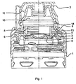
- the closure parts comprise the closure housing 1 and the cover 2, which are interconnected by the tamper-evident 9, as well as consisting of the valve holder 3, the valve counter-holder 4 and the valve 5 valve insert.
- the cover 2 is connected to the closure housing 1 by a film hinge to be recognized on the upper left edge of the picture and has at the upper right edge a small projection on which the user can push up the cover 2 with his thumb and thus open it.
- the cover 2 encloses both the upper part of the closure housing 1 from the outside and the outlet nozzle by a pin projecting downwardly from the inside of the cover plate.
- valve core Inside the closure housing 1 is located in a concentric position of the valve core.
- the elastomer used may preferably be silicone or a thermoplastic elastomer.
- the elastomeric membrane has essentially the shape of a spherical cap. It lies on the underside of the valve holder 3 on a peripheral to the ball cap flange and is fixed by the annular, pressed into the valve holder 3 from below valve counter-holder 4.
- the valve 5 and the valve counter-holder 4 can also be made of one piece.
- the three or two mentioned individual parts of the valve insert are connected to one another in a preceding assembly step and viewed in the context of the method according to the invention as a single closure part.
- the entire closure is flooded with a sterilizing liquid.
- the valve insert as in Fig. 1 shown, first preassembled in step a) of the method according to the invention in a pre-locking position 13.
- This pre-locking position is defined by the narrow annular projection at the upper end of the valve holder 3 (see above all the left side of the valve holder 3), which engages in an annular groove on the inside of the closure housing 1.
- the valve holder 3 has at one point on the circumference of its upper edge a return at which the latching is interrupted and the opening is formed. Furthermore, the sterilization liquid penetrates from the top through the opening 8 into the interior of the valve insert to the top of the valve 5 a.
- the sterilization fluid can not penetrate into the interspace 11 between the closure housing 1 and the cover 2 due to the pin closing the outlet nozzle on the inside of the cover plate.
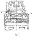
- step c) of the method according to the invention finally the pre-assembled closure is mounted on the beverage bottle by screwing.
- the threads required for this purpose in the interior of the closure housing 1 are at the oblique, tongue-shaped strips in the lower part of the closure housing 1 to recognize.
- valve insert thereby assumes its final assembly position 14 in the closure housing 1 by the annular projection on the upper edge of the valve holder 3 above the upper annular projection on the inside of the closure housing 1 is locked.
- the sharp-edged annular projection 12 is pressed on the flat top of the valve holder 3 (in the drawings at the two upwardly pointing teeth) from below into the material of the closure housing 1. In this way, the opening 6 is closed, and it is made a particularly tight connection between the valve core and the closure housing 1.
Landscapes
- Engineering & Computer Science (AREA)
- Mechanical Engineering (AREA)
- Closures For Containers (AREA)
- Basic Packing Technique (AREA)
Priority Applications (1)
| Application Number | Priority Date | Filing Date | Title |
|---|---|---|---|
| PL11004939T PL2397418T3 (pl) | 2010-06-21 | 2011-06-16 | Sposób montażu wieloczęściowego zamknięcia do pojemników i wieloczęściowe zamknięcie |
Applications Claiming Priority (1)
| Application Number | Priority Date | Filing Date | Title |
|---|---|---|---|
| DE102010024434A DE102010024434A1 (de) | 2010-06-21 | 2010-06-21 | Verfahren zur Montage eines mehrteiligen Verschlusses für Behälter für flüssige, pastöse oder pulverförmige Produkte und mit dem Verfahren montierbarer mehrteiliger Verschluss |
Publications (2)
| Publication Number | Publication Date |
|---|---|
| EP2397418A1 EP2397418A1 (de) | 2011-12-21 |
| EP2397418B1 true EP2397418B1 (de) | 2016-02-17 |
Family
ID=44454538
Family Applications (1)
| Application Number | Title | Priority Date | Filing Date |
|---|---|---|---|
| EP11004939.2A Active EP2397418B1 (de) | 2010-06-21 | 2011-06-16 | Verfahren zur Montage eines mehrteiligen Verschlusses für Behälter und mehrteiliger Verschluss |
Country Status (4)
| Country | Link |
|---|---|
| EP (1) | EP2397418B1 (pl) |
| DE (1) | DE102010024434A1 (pl) |
| ES (1) | ES2571686T3 (pl) |
| PL (1) | PL2397418T3 (pl) |
Family Cites Families (10)
| Publication number | Priority date | Publication date | Assignee | Title |
|---|---|---|---|---|
| US3164279A (en) * | 1965-01-05 | Test tube closure | ||
| NL302611A (pl) * | 1963-01-04 | |||
| US3530979A (en) * | 1967-02-16 | 1970-09-29 | Gerber Prod | Nipple assembly |
| IT1055469B (it) * | 1975-03-07 | 1981-12-21 | Krautkraemer G | Dispositivo di chiusura di materia artificiale per recipienti di imballaggio |
| DE50011575D1 (de) * | 1999-07-29 | 2005-12-15 | Weener Plastik Gmbh Co Kg | Selbstschliessendes ventil |
| DE20116142U1 (de) * | 2001-01-18 | 2002-01-17 | KRONES AG, 93073 Neutraubling | Verschluss für eine Getränkeflasche und Getränkeflasche mit Verschluss |
| US6644487B2 (en) * | 2001-08-17 | 2003-11-11 | Seaquist Closures Foreign, Inc. | Tamper-evident closure with break-off piece retention |
| US7387220B2 (en) * | 2004-08-30 | 2008-06-17 | Scholle Corporation | Cap assembly and container used therewith |
| TWI472459B (zh) * | 2008-05-19 | 2015-02-11 | Melrose David | 移除真空壓力之頂部空間改性方法及其裝置 |
| DE202009000138U1 (de) * | 2009-01-05 | 2009-03-19 | Weener Plastik Ag | Klappverschluss |
-
2010
- 2010-06-21 DE DE102010024434A patent/DE102010024434A1/de active Pending
-
2011
- 2011-06-16 ES ES11004939T patent/ES2571686T3/es active Active
- 2011-06-16 EP EP11004939.2A patent/EP2397418B1/de active Active
- 2011-06-16 PL PL11004939T patent/PL2397418T3/pl unknown
Also Published As
| Publication number | Publication date |
|---|---|
| EP2397418A1 (de) | 2011-12-21 |
| PL2397418T3 (pl) | 2016-08-31 |
| DE102010024434A1 (de) | 2011-12-22 |
| ES2571686T3 (es) | 2016-05-26 |
Similar Documents
| Publication | Publication Date | Title |
|---|---|---|
| DE102014113392B4 (de) | Verschlussvorrichtung für einen Behälter | |
| DE69918993T2 (de) | Verschliessbare Öffnungsvorrichtung für Packungen für fliessfähige Nahrungsmittel | |
| DE60031392T2 (de) | Behälterverschluss | |
| DE69300460T2 (de) | Verbesserungen an Zapfhähnen. | |
| EP0137458A2 (de) | Öffnungs- und Entnahmekappe | |
| DE3535520A1 (de) | Behaelter mit membranabdichtung und ausgiessverschluss mit sicherheitsstreifen | |
| DE19544708A1 (de) | Behälter, Behälterverschlußkappe, Verfahren und Maschine zum kaltaseptischen Befüllen mit Getränken | |
| EP1595810A1 (de) | Behälter mit Inliner-Beutel und Einweg-Spenderventil | |
| EP2296993A1 (de) | Verschlussvorrichtung für einen behälter | |
| CH700493B1 (de) | Verschluss für eine Trinkflasche. | |
| EP0355795B1 (de) | Adapter zum Anschliessen von enteralen Überleitungsgeräten | |
| WO2013124483A2 (de) | Durchstechbarer kunststoffverschluss zum verschliessen von behältnissen | |
| EP1590257A1 (de) | Einwegventileinrichtung | |
| DE102008056301B4 (de) | Vorrichtung zum Öffnen und Verschließen eines Getränkebehälters | |
| WO2009132609A1 (de) | Tubenverpackung | |
| EP2397418B1 (de) | Verfahren zur Montage eines mehrteiligen Verschlusses für Behälter und mehrteiliger Verschluss | |
| EP1847470A2 (de) | Verschluss für ein Behältnis | |
| WO2020070548A1 (de) | Vorrichtung zur teilöffnung und zum verschluss von dosen | |
| EP1534592B1 (de) | Verfahren zum applizieren eines wiederverschliessbaren ausgiesselements an einen behälter und behälter dafür | |
| DE102006047593B4 (de) | Verschluss | |
| EP1571095B1 (de) | Vorrichtung zum Öffnen eines Behälters sowie Verfahren zum Festfügen eines Wirkstoffes an einer solchen Vorrichtung | |
| DE102005022952B3 (de) | Kombination eines Originalitäts-Verschlusses mit einer Behälteröffnung | |
| EP1542909B1 (de) | Dosenverschluss, dosendeckel und dose | |
| DE3149780A1 (de) | Behaelter, insbesondere flasche aus kunststoff | |
| EP1922261A1 (de) | Gasdichter stutzenverschluss mit öffnungseinrichtung |
Legal Events
| Date | Code | Title | Description |
|---|---|---|---|
| AK | Designated contracting states |
Kind code of ref document: A1 Designated state(s): AL AT BE BG CH CY CZ DE DK EE ES FI FR GB GR HR HU IE IS IT LI LT LU LV MC MK MT NL NO PL PT RO RS SE SI SK SM TR |
|
| AX | Request for extension of the european patent |
Extension state: BA ME |
|
| PUAI | Public reference made under article 153(3) epc to a published international application that has entered the european phase |
Free format text: ORIGINAL CODE: 0009012 |
|
| 17P | Request for examination filed |
Effective date: 20120131 |
|
| 17Q | First examination report despatched |
Effective date: 20120913 |
|
| RIN1 | Information on inventor provided before grant (corrected) |
Inventor name: SCHIPPER, MICHAEL Inventor name: PROX, MATTHIAS, DR. |
|
| GRAP | Despatch of communication of intention to grant a patent |
Free format text: ORIGINAL CODE: EPIDOSNIGR1 |
|
| RIC1 | Information provided on ipc code assigned before grant |
Ipc: B65D 47/08 20060101AFI20150929BHEP Ipc: B65D 41/32 20060101ALI20150929BHEP Ipc: B65D 47/20 20060101ALI20150929BHEP Ipc: B67B 3/00 20060101ALI20150929BHEP |
|
| INTG | Intention to grant announced |
Effective date: 20151014 |
|
| GRAS | Grant fee paid |
Free format text: ORIGINAL CODE: EPIDOSNIGR3 |
|
| GRAA | (expected) grant |
Free format text: ORIGINAL CODE: 0009210 |
|
| RAP1 | Party data changed (applicant data changed or rights of an application transferred) |
Owner name: WEENER PLASTIK GMBH |
|
| AK | Designated contracting states |
Kind code of ref document: B1 Designated state(s): AL AT BE BG CH CY CZ DE DK EE ES FI FR GB GR HR HU IE IS IT LI LT LU LV MC MK MT NL NO PL PT RO RS SE SI SK SM TR |
|
| REG | Reference to a national code |
Ref country code: GB Ref legal event code: FG4D Free format text: NOT ENGLISH |
|
| REG | Reference to a national code |
Ref country code: CH Ref legal event code: EP |
|
| REG | Reference to a national code |
Ref country code: IE Ref legal event code: FG4D Free format text: LANGUAGE OF EP DOCUMENT: GERMAN |
|
| REG | Reference to a national code |
Ref country code: AT Ref legal event code: REF Ref document number: 775527 Country of ref document: AT Kind code of ref document: T Effective date: 20160315 |
|
| REG | Reference to a national code |
Ref country code: DE Ref legal event code: R096 Ref document number: 502011008890 Country of ref document: DE |
|
| REG | Reference to a national code |
Ref country code: ES Ref legal event code: FG2A Ref document number: 2571686 Country of ref document: ES Kind code of ref document: T3 Effective date: 20160526 |
|
| REG | Reference to a national code |
Ref country code: FR Ref legal event code: PLFP Year of fee payment: 6 |
|
| REG | Reference to a national code |
Ref country code: NL Ref legal event code: MP Effective date: 20160217 |
|
| REG | Reference to a national code |
Ref country code: LT Ref legal event code: MG4D |
|
| PG25 | Lapsed in a contracting state [announced via postgrant information from national office to epo] |
Ref country code: FI Free format text: LAPSE BECAUSE OF FAILURE TO SUBMIT A TRANSLATION OF THE DESCRIPTION OR TO PAY THE FEE WITHIN THE PRESCRIBED TIME-LIMIT Effective date: 20160217 Ref country code: NO Free format text: LAPSE BECAUSE OF FAILURE TO SUBMIT A TRANSLATION OF THE DESCRIPTION OR TO PAY THE FEE WITHIN THE PRESCRIBED TIME-LIMIT Effective date: 20160517 Ref country code: GR Free format text: LAPSE BECAUSE OF FAILURE TO SUBMIT A TRANSLATION OF THE DESCRIPTION OR TO PAY THE FEE WITHIN THE PRESCRIBED TIME-LIMIT Effective date: 20160518 |
|
| PG25 | Lapsed in a contracting state [announced via postgrant information from national office to epo] |
Ref country code: PT Free format text: LAPSE BECAUSE OF FAILURE TO SUBMIT A TRANSLATION OF THE DESCRIPTION OR TO PAY THE FEE WITHIN THE PRESCRIBED TIME-LIMIT Effective date: 20160617 Ref country code: LT Free format text: LAPSE BECAUSE OF FAILURE TO SUBMIT A TRANSLATION OF THE DESCRIPTION OR TO PAY THE FEE WITHIN THE PRESCRIBED TIME-LIMIT Effective date: 20160217 Ref country code: SE Free format text: LAPSE BECAUSE OF FAILURE TO SUBMIT A TRANSLATION OF THE DESCRIPTION OR TO PAY THE FEE WITHIN THE PRESCRIBED TIME-LIMIT Effective date: 20160217 Ref country code: LV Free format text: LAPSE BECAUSE OF FAILURE TO SUBMIT A TRANSLATION OF THE DESCRIPTION OR TO PAY THE FEE WITHIN THE PRESCRIBED TIME-LIMIT Effective date: 20160217 Ref country code: NL Free format text: LAPSE BECAUSE OF FAILURE TO SUBMIT A TRANSLATION OF THE DESCRIPTION OR TO PAY THE FEE WITHIN THE PRESCRIBED TIME-LIMIT Effective date: 20160217 Ref country code: RS Free format text: LAPSE BECAUSE OF FAILURE TO SUBMIT A TRANSLATION OF THE DESCRIPTION OR TO PAY THE FEE WITHIN THE PRESCRIBED TIME-LIMIT Effective date: 20160217 |
|
| PG25 | Lapsed in a contracting state [announced via postgrant information from national office to epo] |
Ref country code: DK Free format text: LAPSE BECAUSE OF FAILURE TO SUBMIT A TRANSLATION OF THE DESCRIPTION OR TO PAY THE FEE WITHIN THE PRESCRIBED TIME-LIMIT Effective date: 20160217 Ref country code: EE Free format text: LAPSE BECAUSE OF FAILURE TO SUBMIT A TRANSLATION OF THE DESCRIPTION OR TO PAY THE FEE WITHIN THE PRESCRIBED TIME-LIMIT Effective date: 20160217 |
|
| REG | Reference to a national code |
Ref country code: DE Ref legal event code: R097 Ref document number: 502011008890 Country of ref document: DE |
|
| PG25 | Lapsed in a contracting state [announced via postgrant information from national office to epo] |
Ref country code: CZ Free format text: LAPSE BECAUSE OF FAILURE TO SUBMIT A TRANSLATION OF THE DESCRIPTION OR TO PAY THE FEE WITHIN THE PRESCRIBED TIME-LIMIT Effective date: 20160217 Ref country code: RO Free format text: LAPSE BECAUSE OF FAILURE TO SUBMIT A TRANSLATION OF THE DESCRIPTION OR TO PAY THE FEE WITHIN THE PRESCRIBED TIME-LIMIT Effective date: 20160217 Ref country code: SM Free format text: LAPSE BECAUSE OF FAILURE TO SUBMIT A TRANSLATION OF THE DESCRIPTION OR TO PAY THE FEE WITHIN THE PRESCRIBED TIME-LIMIT Effective date: 20160217 Ref country code: SK Free format text: LAPSE BECAUSE OF FAILURE TO SUBMIT A TRANSLATION OF THE DESCRIPTION OR TO PAY THE FEE WITHIN THE PRESCRIBED TIME-LIMIT Effective date: 20160217 |
|
| PLBE | No opposition filed within time limit |
Free format text: ORIGINAL CODE: 0009261 |
|
| STAA | Information on the status of an ep patent application or granted ep patent |
Free format text: STATUS: NO OPPOSITION FILED WITHIN TIME LIMIT |
|
| PG25 | Lapsed in a contracting state [announced via postgrant information from national office to epo] |
Ref country code: BE Free format text: LAPSE BECAUSE OF NON-PAYMENT OF DUE FEES Effective date: 20160630 |
|
| 26N | No opposition filed |
Effective date: 20161118 |
|
| PG25 | Lapsed in a contracting state [announced via postgrant information from national office to epo] |
Ref country code: MC Free format text: LAPSE BECAUSE OF FAILURE TO SUBMIT A TRANSLATION OF THE DESCRIPTION OR TO PAY THE FEE WITHIN THE PRESCRIBED TIME-LIMIT Effective date: 20160217 |
|
| REG | Reference to a national code |
Ref country code: CH Ref legal event code: PL |
|
| PG25 | Lapsed in a contracting state [announced via postgrant information from national office to epo] |
Ref country code: BG Free format text: LAPSE BECAUSE OF FAILURE TO SUBMIT A TRANSLATION OF THE DESCRIPTION OR TO PAY THE FEE WITHIN THE PRESCRIBED TIME-LIMIT Effective date: 20160517 Ref country code: SI Free format text: LAPSE BECAUSE OF FAILURE TO SUBMIT A TRANSLATION OF THE DESCRIPTION OR TO PAY THE FEE WITHIN THE PRESCRIBED TIME-LIMIT Effective date: 20160217 |
|
| REG | Reference to a national code |
Ref country code: IE Ref legal event code: MM4A |
|
| PG25 | Lapsed in a contracting state [announced via postgrant information from national office to epo] |
Ref country code: LI Free format text: LAPSE BECAUSE OF NON-PAYMENT OF DUE FEES Effective date: 20160630 Ref country code: CH Free format text: LAPSE BECAUSE OF NON-PAYMENT OF DUE FEES Effective date: 20160630 |
|
| PG25 | Lapsed in a contracting state [announced via postgrant information from national office to epo] |
Ref country code: IE Free format text: LAPSE BECAUSE OF NON-PAYMENT OF DUE FEES Effective date: 20160616 |
|
| REG | Reference to a national code |
Ref country code: FR Ref legal event code: PLFP Year of fee payment: 7 |
|
| REG | Reference to a national code |
Ref country code: AT Ref legal event code: MM01 Ref document number: 775527 Country of ref document: AT Kind code of ref document: T Effective date: 20160616 |
|
| PG25 | Lapsed in a contracting state [announced via postgrant information from national office to epo] |
Ref country code: AT Free format text: LAPSE BECAUSE OF NON-PAYMENT OF DUE FEES Effective date: 20160616 |
|
| PG25 | Lapsed in a contracting state [announced via postgrant information from national office to epo] |
Ref country code: HU Free format text: LAPSE BECAUSE OF FAILURE TO SUBMIT A TRANSLATION OF THE DESCRIPTION OR TO PAY THE FEE WITHIN THE PRESCRIBED TIME-LIMIT; INVALID AB INITIO Effective date: 20110616 Ref country code: CY Free format text: LAPSE BECAUSE OF FAILURE TO SUBMIT A TRANSLATION OF THE DESCRIPTION OR TO PAY THE FEE WITHIN THE PRESCRIBED TIME-LIMIT Effective date: 20160217 |
|
| REG | Reference to a national code |
Ref country code: FR Ref legal event code: PLFP Year of fee payment: 8 |
|
| PG25 | Lapsed in a contracting state [announced via postgrant information from national office to epo] |
Ref country code: MT Free format text: LAPSE BECAUSE OF FAILURE TO SUBMIT A TRANSLATION OF THE DESCRIPTION OR TO PAY THE FEE WITHIN THE PRESCRIBED TIME-LIMIT Effective date: 20160217 Ref country code: HR Free format text: LAPSE BECAUSE OF FAILURE TO SUBMIT A TRANSLATION OF THE DESCRIPTION OR TO PAY THE FEE WITHIN THE PRESCRIBED TIME-LIMIT Effective date: 20160217 Ref country code: IS Free format text: LAPSE BECAUSE OF FAILURE TO SUBMIT A TRANSLATION OF THE DESCRIPTION OR TO PAY THE FEE WITHIN THE PRESCRIBED TIME-LIMIT Effective date: 20160217 Ref country code: MK Free format text: LAPSE BECAUSE OF FAILURE TO SUBMIT A TRANSLATION OF THE DESCRIPTION OR TO PAY THE FEE WITHIN THE PRESCRIBED TIME-LIMIT Effective date: 20160217 Ref country code: TR Free format text: LAPSE BECAUSE OF FAILURE TO SUBMIT A TRANSLATION OF THE DESCRIPTION OR TO PAY THE FEE WITHIN THE PRESCRIBED TIME-LIMIT Effective date: 20160217 Ref country code: LU Free format text: LAPSE BECAUSE OF NON-PAYMENT OF DUE FEES Effective date: 20160616 |
|
| PG25 | Lapsed in a contracting state [announced via postgrant information from national office to epo] |
Ref country code: AL Free format text: LAPSE BECAUSE OF FAILURE TO SUBMIT A TRANSLATION OF THE DESCRIPTION OR TO PAY THE FEE WITHIN THE PRESCRIBED TIME-LIMIT Effective date: 20160217 |
|
| P01 | Opt-out of the competence of the unified patent court (upc) registered |
Effective date: 20230505 |
|
| PGFP | Annual fee paid to national office [announced via postgrant information from national office to epo] |
Ref country code: IT Payment date: 20230630 Year of fee payment: 13 |
|
| PGFP | Annual fee paid to national office [announced via postgrant information from national office to epo] |
Ref country code: GB Payment date: 20240620 Year of fee payment: 14 |
|
| PGFP | Annual fee paid to national office [announced via postgrant information from national office to epo] |
Ref country code: DE Payment date: 20240617 Year of fee payment: 14 |
|
| PGFP | Annual fee paid to national office [announced via postgrant information from national office to epo] |
Ref country code: FR Payment date: 20240621 Year of fee payment: 14 |
|
| PGFP | Annual fee paid to national office [announced via postgrant information from national office to epo] |
Ref country code: PL Payment date: 20240531 Year of fee payment: 14 |
|
| PGFP | Annual fee paid to national office [announced via postgrant information from national office to epo] |
Ref country code: ES Payment date: 20240718 Year of fee payment: 14 |
|
| PG25 | Lapsed in a contracting state [announced via postgrant information from national office to epo] |
Ref country code: IT Free format text: LAPSE BECAUSE OF NON-PAYMENT OF DUE FEES Effective date: 20240616 |