EP2397359B1 - Hybrider motorbetriebener Stromgenerator - Google Patents
Hybrider motorbetriebener Stromgenerator Download PDFInfo
- Publication number
- EP2397359B1 EP2397359B1 EP11164614.7A EP11164614A EP2397359B1 EP 2397359 B1 EP2397359 B1 EP 2397359B1 EP 11164614 A EP11164614 A EP 11164614A EP 2397359 B1 EP2397359 B1 EP 2397359B1
- Authority
- EP
- European Patent Office
- Prior art keywords
- battery
- output
- power generator
- current
- engine
- Prior art date
- Legal status (The legal status is an assumption and is not a legal conclusion. Google has not performed a legal analysis and makes no representation as to the accuracy of the status listed.)
- Not-in-force
Links
- 230000004044 response Effects 0.000 claims description 2
- 238000012545 processing Methods 0.000 description 13
- 238000010586 diagram Methods 0.000 description 11
- 238000004804 winding Methods 0.000 description 11
- 230000001965 increasing effect Effects 0.000 description 6
- 239000003990 capacitor Substances 0.000 description 5
- 230000007423 decrease Effects 0.000 description 5
- 230000006870 function Effects 0.000 description 5
- 238000007493 shaping process Methods 0.000 description 5
- 230000009467 reduction Effects 0.000 description 4
- 230000008859 change Effects 0.000 description 3
- 238000007796 conventional method Methods 0.000 description 3
- 230000008878 coupling Effects 0.000 description 3
- 238000010168 coupling process Methods 0.000 description 3
- 238000005859 coupling reaction Methods 0.000 description 3
- 238000006243 chemical reaction Methods 0.000 description 2
- 230000003247 decreasing effect Effects 0.000 description 2
- 238000001514 detection method Methods 0.000 description 2
- 230000002708 enhancing effect Effects 0.000 description 2
- 230000007246 mechanism Effects 0.000 description 2
- 238000000034 method Methods 0.000 description 2
- 239000007858 starting material Substances 0.000 description 2
- 230000015556 catabolic process Effects 0.000 description 1
- LFHISGNCFUNFFM-UHFFFAOYSA-N chloropicrin Chemical compound [O-][N+](=O)C(Cl)(Cl)Cl LFHISGNCFUNFFM-UHFFFAOYSA-N 0.000 description 1
- 239000000571 coke Substances 0.000 description 1
- 230000000694 effects Effects 0.000 description 1
- 238000009499 grossing Methods 0.000 description 1
- 238000012986 modification Methods 0.000 description 1
- 230000004048 modification Effects 0.000 description 1
- 230000003071 parasitic effect Effects 0.000 description 1
- 230000001360 synchronised effect Effects 0.000 description 1
Images


Classifications
-
- H—ELECTRICITY
- H02—GENERATION; CONVERSION OR DISTRIBUTION OF ELECTRIC POWER
- H02P—CONTROL OR REGULATION OF ELECTRIC MOTORS, ELECTRIC GENERATORS OR DYNAMO-ELECTRIC CONVERTERS; CONTROLLING TRANSFORMERS, REACTORS OR CHOKE COILS
- H02P9/00—Arrangements for controlling electric generators for the purpose of obtaining a desired output
- H02P9/04—Control effected upon non-electric prime mover and dependent upon electric output value of the generator
-
- B—PERFORMING OPERATIONS; TRANSPORTING
- B60—VEHICLES IN GENERAL
- B60L—PROPULSION OF ELECTRICALLY-PROPELLED VEHICLES; SUPPLYING ELECTRIC POWER FOR AUXILIARY EQUIPMENT OF ELECTRICALLY-PROPELLED VEHICLES; ELECTRODYNAMIC BRAKE SYSTEMS FOR VEHICLES IN GENERAL; MAGNETIC SUSPENSION OR LEVITATION FOR VEHICLES; MONITORING OPERATING VARIABLES OF ELECTRICALLY-PROPELLED VEHICLES; ELECTRIC SAFETY DEVICES FOR ELECTRICALLY-PROPELLED VEHICLES
- B60L50/00—Electric propulsion with power supplied within the vehicle
- B60L50/10—Electric propulsion with power supplied within the vehicle using propulsion power supplied by engine-driven generators, e.g. generators driven by combustion engines
- B60L50/15—Electric propulsion with power supplied within the vehicle using propulsion power supplied by engine-driven generators, e.g. generators driven by combustion engines with additional electric power supply
-
- B—PERFORMING OPERATIONS; TRANSPORTING
- B60—VEHICLES IN GENERAL
- B60L—PROPULSION OF ELECTRICALLY-PROPELLED VEHICLES; SUPPLYING ELECTRIC POWER FOR AUXILIARY EQUIPMENT OF ELECTRICALLY-PROPELLED VEHICLES; ELECTRODYNAMIC BRAKE SYSTEMS FOR VEHICLES IN GENERAL; MAGNETIC SUSPENSION OR LEVITATION FOR VEHICLES; MONITORING OPERATING VARIABLES OF ELECTRICALLY-PROPELLED VEHICLES; ELECTRIC SAFETY DEVICES FOR ELECTRICALLY-PROPELLED VEHICLES
- B60L2210/00—Converter types
- B60L2210/10—DC to DC converters
-
- Y—GENERAL TAGGING OF NEW TECHNOLOGICAL DEVELOPMENTS; GENERAL TAGGING OF CROSS-SECTIONAL TECHNOLOGIES SPANNING OVER SEVERAL SECTIONS OF THE IPC; TECHNICAL SUBJECTS COVERED BY FORMER USPC CROSS-REFERENCE ART COLLECTIONS [XRACs] AND DIGESTS
- Y02—TECHNOLOGIES OR APPLICATIONS FOR MITIGATION OR ADAPTATION AGAINST CLIMATE CHANGE
- Y02T—CLIMATE CHANGE MITIGATION TECHNOLOGIES RELATED TO TRANSPORTATION
- Y02T10/00—Road transport of goods or passengers
- Y02T10/60—Other road transportation technologies with climate change mitigation effect
- Y02T10/64—Electric machine technologies in electromobility
-
- Y—GENERAL TAGGING OF NEW TECHNOLOGICAL DEVELOPMENTS; GENERAL TAGGING OF CROSS-SECTIONAL TECHNOLOGIES SPANNING OVER SEVERAL SECTIONS OF THE IPC; TECHNICAL SUBJECTS COVERED BY FORMER USPC CROSS-REFERENCE ART COLLECTIONS [XRACs] AND DIGESTS
- Y02—TECHNOLOGIES OR APPLICATIONS FOR MITIGATION OR ADAPTATION AGAINST CLIMATE CHANGE
- Y02T—CLIMATE CHANGE MITIGATION TECHNOLOGIES RELATED TO TRANSPORTATION
- Y02T10/00—Road transport of goods or passengers
- Y02T10/60—Other road transportation technologies with climate change mitigation effect
- Y02T10/70—Energy storage systems for electromobility, e.g. batteries
-
- Y—GENERAL TAGGING OF NEW TECHNOLOGICAL DEVELOPMENTS; GENERAL TAGGING OF CROSS-SECTIONAL TECHNOLOGIES SPANNING OVER SEVERAL SECTIONS OF THE IPC; TECHNICAL SUBJECTS COVERED BY FORMER USPC CROSS-REFERENCE ART COLLECTIONS [XRACs] AND DIGESTS
- Y02—TECHNOLOGIES OR APPLICATIONS FOR MITIGATION OR ADAPTATION AGAINST CLIMATE CHANGE
- Y02T—CLIMATE CHANGE MITIGATION TECHNOLOGIES RELATED TO TRANSPORTATION
- Y02T10/00—Road transport of goods or passengers
- Y02T10/60—Other road transportation technologies with climate change mitigation effect
- Y02T10/7072—Electromobility specific charging systems or methods for batteries, ultracapacitors, supercapacitors or double-layer capacitors
-
- Y—GENERAL TAGGING OF NEW TECHNOLOGICAL DEVELOPMENTS; GENERAL TAGGING OF CROSS-SECTIONAL TECHNOLOGIES SPANNING OVER SEVERAL SECTIONS OF THE IPC; TECHNICAL SUBJECTS COVERED BY FORMER USPC CROSS-REFERENCE ART COLLECTIONS [XRACs] AND DIGESTS
- Y02—TECHNOLOGIES OR APPLICATIONS FOR MITIGATION OR ADAPTATION AGAINST CLIMATE CHANGE
- Y02T—CLIMATE CHANGE MITIGATION TECHNOLOGIES RELATED TO TRANSPORTATION
- Y02T10/00—Road transport of goods or passengers
- Y02T10/60—Other road transportation technologies with climate change mitigation effect
- Y02T10/72—Electric energy management in electromobility
Definitions
- the present invention relates to a hybrid engine-driven power generator according to the preamble of claim 1, and particularly to a hybrid engine-driven power generator suitable for preventing a drooping time of an engine frequency and a reduction time of a generator output voltage from elongating during load inrush (including a change period from a low load to a high load), enhancing a starting performance, and restricting a reduction of the generator output.
- a hybrid engine-driven power generator including a rectifier for converting an AC 3-phase output voltage from an alternator driven by an engine into a DC voltage, an inverter for converting the DC output of the rectifier into an AC output voltage, a filter circuit, a battery, a DC/DC converter for boosting a DC voltage of the battery and supplying the same between the rectifier and the inverter, and a control part for controlling the outputs of the inverter and the DC/DC converter.
- the hybrid engine-driven power generator of this type is described in Japanese Patent Publication No. JP 3941927 B , for example.
- JP 4082657 B describes therein, for example, a structure of the hybrid engine-driven power generator in which the DC voltage of the battery is boosted and supplied to the DC/DC converter during an overload while when an external load current is larger than a rated current value, the voltage of the inverter is changed according to a preset map.
- a hybrid engine-driven power generator according to the preamble of claim 1 is known from US 2004/008009 A1 .
- US 2008/116695 A1 discloses a further hybrid engine-driven power generator, in which an engine is completely stopped at a silent (or quiet) operation mode.
- a load can be started without stalling the engine even when an inrush current occurs during an increased load.
- an inrush current occurs, an amplitude of an output sinusoidal wave is temporarily reduced and thus an input voltage of the inverter is reduced, a load start time can be elongated or a load cannot be started (can be reset) due to the reduction in voltage, which are the problems to solve.
- a first feature of the present invention is a hybrid engine-driven power generator which comprises a power generator driven by an engine and a battery for power generator main bodies, and has a rectifier for rectifying an output of the power generator, an inverter for converting an output of the rectifier into an AC output to be a generator output, and a DC/DC converter for boosting a DC voltage of the battery and inputting the boosted voltage into the inverter, comprising: an engine revolution frequency detecting means; a means for calculating an outputtable current of the power generator corresponding to an engine revolution frequency; a load current detecting means; a means for calculating the lacking amount of the outputtable current of the power generator corresponding to the load current; a controlling means for controlling the DC/DC converter in order to supply a current corresponding to the lacking amount of the current value from the battery to the inverter; a means for detecting a terminal voltage of the battery; and a means for deciding whether the terminal voltage of the battery is a reference voltage or more for deciding the remaining amount of the battery,
- a second feature of the present invention is the hybrid engine-driven power generator comprising: an engine revolution frequency deciding means for deciding whether the engine revolution frequency is stable within a preset range of a target engine revolution frequency decided depending on the load current, wherein when it is decided that the engine revolution frequency is in the stable state, the output from the power generator is started and the output from the battery is reduced.
- a third feature of the present invention is the hybrid engine-driven power generator, wherein the shortage of the current value due to the battery output is compensated according to preset output ratios of the power generator and the battery.
- the lacking load current due to the generator output can be compensated by an output of the battery and thus the engine load can be avoided from increasing too much and the engine can be prevented from being stalled.
- the battery output assists the generator output when the remaining amount of the battery is sufficient, an overdischarge of the battery can be prevented.
- the generator output is temporarily stopped when the battery starts outputting, a reduction in engine frequency due to an increased load on the engine can be prevented, thereby starting the engine in a short time up to the frequency depending on the load while the battery output is meeting the load, and enhancing the load starting characteristics.
- the generator output voltage of the hybrid engine-driven power generator can be prevented from reducing when a load is switched or a load is powered on.
- the battery output can assist the generator output in a predetermined range, thereby alleviating the load of the battery.
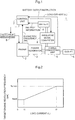
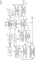
- Fig. 1 is a system structure diagram of a hybrid engine-driven power generator according to one embodiment of the present invention.
- the hybrid engine-driven power generator 1 has a power generator 3 connected to an engine 2 and driven by the engine 2.
- the power generator 3 is a 3-phase multipolar magnet power generator, for example.
- An output side of the power generator 3 is connected to a power converting part 5.
- the power converting part 5 rectifies, reduces and converts a generator output of the power generator 3 into an AC output having a predetermined frequency, and further performs a filter processing on the generator output to be connected to an outlet 6 as an output terminal.
- a battery 4 is connected to the power converting part 5 via an insulative DC/DC converter 9, and a current by the generator output of the power generator 3 and a current by a power of the battery 4 are summed up to be supplied to the outlet 6.
- a control unit (control part) 7 calculates a target engine frequency depending on the load current IL.
- the target engine frequency associated with the load current IL is previously stored as a map in a memory, and the map is retrieved to find the target engine frequency.
- the control part 7 controls a governor mechanism 8 and adjusts a throttle aperture of the engine 2 such that an engine frequency Ne detected by a frequency sensor (a well-known sensor is available) of the engine 2 converges on the target engine frequency.
- the control part 7 can supply a battery output instruction to the DC/DC converter 9, and the DC/DC converter 9 controls an input from the battery 4 according to the battery output instruction and supplies a power saved in the battery 4 to the power converting part 5.
- Battery information (such as battery voltage) is considered for the battery output instruction.
- Fig. 2 is a diagram showing one example of the map in which the target engine frequency is set in relation with the load current IL.
- the target engine frequency is set at an idle frequency Neidl (such as 2500 rpm) while the load current IL is between zero and I1, the target engine frequency increases along with an increase in load current IL, and the target engine frequency is set at the maximum value Nemax when the load current IL reaches I2.
- Neidl such as 2500 rpm
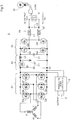
- Fig. 3 is a circuit diagram showing a specific structure of the hybrid engine-driven power generator.
- the power converting part 5 is formed of a rectifying part 51, an DC part 52, an inverter 53 and a waveform shaping circuit 54.
- the rectifying part 51 is a bridge rectifying circuit having bridge-connected FETs Qa, Qb, Qc, Qd, Qe and Qf.
- a 3-phase winding 3U, a 3-phase winding 3V and a 3-phase winding 3W of an alternator 3 are connected to a coupling point between the FET Q1 and the FET Qd, a coupling point between the FET Qb and the FET Qe and a coupling point between the FET Qc and the FET Q8f respectively.
- the DC part 52 is a voltage converting circuit (voltage reducing DC/DC converter), and includes the switching device (FET) Q1 and a choke coil L3 which are connected to an output line of the rectifying part 51 in series, and a diode D7 connected to the output line of the rectifying part 51 in parallel.
- Capacitors C1, C2 are connected to an input side and an output side of the AC part 52 in parallel, respectively.
- the inverter part 53 is formed by bridge-connecting four FETs Q2, Q3, Q4 and Q5.
- the waveform shaping circuit 54 is formed of coils L1, L2 and a capacitor C3.
- the FET Q1 of the DC part 52, the FETs Q2 to Q5 of the inverter part 53 and the FETs Qa to Qf of the rectifying part 51 are PWM-controlled by the control part 7.
- the DC part 52 reduces an input DC voltage.
- the inverter part 53 converts an input voltage into an AC voltage having a predetermined frequency and inputs the AC voltage into the waveform shaping circuit 54.
- An output side of the waveform shaping circuit 54 is connected to the outlet 6 for extracting a generator output to the outside.
- a load 16 is connected to the outlet 6.
- the battery 4 is connected to an input side of the insulative DC/DC converter 9, and an output side of the insulative DC/DC converter 9 is connected to the input side of the AC part 52.
- An output power of the battery 4 is boosted in the insulative DC/DC converter 9 and is input into the AC part 52.
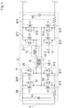
- Fig. 4 is a circuit diagram showing a structure example of the insulative DC/DC converter 9.
- the insulative DC/DC converter 9 includes a transformer 10 including a low voltage side winding 10-1 at the primary side and a high voltage side winding 10-2 at the secondary side.
- a boosted voltage ratio of the insulative DC/DC converter 9 is determined by a winding ratio of the low voltage side winding 10-1 relative to the high voltage side winding 10-2.
- a low voltage side switching part 11 is connected to the low voltage side winding 10-1 and a high voltage side switching part 12 is connected to the high voltage side winding 10-2.
- the low voltage side switching part 11 is configured, for example, by bridge-connecting four FETs Q9, Q10, Q11 and Q12, and the high voltage side switching part 12 is also formed by bridge-connecting four FETs Q13, Q14, Q15 and Q16 similarly.
- the FETs Q9 to Q16 of the low voltage side switching part 11 and the high voltage side switching part 12 are connected with diodes D7, D8, D9, D10 and D11, D12, D13, D14 in parallel, respectively. These diodes may be parasitic diodes of the FETs or additionally-connected diodes.
- the low voltage side switching part 11 and the high voltage side switching part 12 may be assumed as a switching/rectifying part in a combination of the rectifying devices D7 to D14 connected in parallel.
- a LC resonance circuit 13 is inserted into the high voltage side winding 10-2 of the transformer 10.
- the LC resonance circuit 13 functions to make a current flowing when at least one of the low voltage side switching part 11 and the high voltage side switching part 12 is driven into a sinusoidal wave form, to reduce a switching loss, and not to cause FET breakdown due to a large current. This is because the FETs can be powered on or off near the zero cross point of the current in a sinusoidal wave form.
- the LC resonance circuit 13 may be provided at the primary side not at the secondary side.
- Capacitors 14, 15 connected to the primary side and the secondary side are output smoothing capacitors.
- the low voltage side switching part 11 and the high voltage side switching part 12 are driven by the same signal to be completely synchronized with each other such that the insulative DC/DC converter 9 automatically performs power conversion bidirectionally.
- Such driving is performed by alternately powering on and off a pair of FETs Q9 and Q12 and a pair of FETs Q10 and Q11 in the low voltage side switching part 11 and alternately powering on and off a pair of FETs Q13 and Q16 and a pair of FETs Q14 and Q15 in the high voltage side switching part 12, as well known.
- Power conversion is performed from the primary side of the insulative DC/DC converter 9 to the secondary side during an engine start, and then the thus boosted DC voltage of the battery 4 is given to the rectifying part 51 that functions as a drive inverter.
- the rectifying part 51 PWM-drives the Qa to Qf as well known, and converts an input DC voltage into a 3-phase AC voltage to be applied to the alternator 3.
- the engine 2 is started.
- a phase can be decided by utilizing a change in current distribution by back electromotive voltage occurring according to the operation of the alternator 3, and can be synchronously driven under sensorless control.
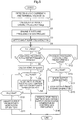
- Fig. 5 is a flowchart showing the operations of the control unit according to a first example of the present embodiment. The processings of the flowchart are performed on interruption for each 10 milliseconds, for example.
- step S1 the load current IL and a terminal voltage Vb of the battery 4 are detected.
- the load current IL is calculated based on voltages detected at both ends of voltage detection resistors capable of being provided between the inverter part 53 and the waveform shaping circuit 54.
- a load current/target frequency map (see Fig. 2 ) is retrieved based on the load current IL to calculate a target engine frequency Netgt.
- the target engine frequency Netgt may be calculated by a preset operational formula.
- step S3 the engine 2 is started, and the throttle aperture is controlled by the governor mechanism 8 such that the engine frequency Ne converges on the target engine frequency Netgt.
- step S4 the engine frequency Ne is detected by a frequency sensor (not shown).
- step S5 a decision is made as to whether the engine frequency Ne substantially converges on the target engine frequency Netgt (for example, whether the engine frequency Ne is within ⁇ 100 rpm of the target engine frequency Netgt), that is, whether the engine frequency Ne is stable. If affirmation is taken in step S5, the processing proceeds to step S6, where a decision is made as to whether the engine frequency Ne has been stabilized for a predetermined period of time (such as 100 milliseconds). In other words, a decision is made as to whether the engine frequency Ne has remained stable for a predetermined period of time. A timer processing for the elapsed time decision is performed in another routine (not shown). Since the target engine frequency Netgt is decided depending on the load current IL, the target engine frequency Netgt also increases or decreases while the load current IL is increasing or decreasing, and the engine frequency Ne is also stabilized when the load is constant.
- the outputtable current Igout of the power generator 3 can be set in the map as a value for the engine frequency Ne, for example.
- Fig. 6 shows an example of the map in which the outputtable current Igout of the power generator 3 is set for the engine frequency Ne. The map is set such that the outputtable current Igout increases as the engine frequency Ne increases.
- step S8 a decision is made as to whether the current difference ⁇ I is zero or more.
- the processing proceeds to step S9, where the DC/DC converter 9 is controlled to stop the output from the battery 4 and to supply all the load currents IL from the power generator 3.
- the target engine frequency Netgt of the engine 2 is decided depending on the load current IL to start the output of the power generator 3.
- the output of the power generator 3 may be assisted at a preset ratio.
- the output of the battery 4 is not immediately made zero and the output ratio of the battery 4 may be gradually reduced depending on an increase in output of the power generator 3.
- step S10 a decision is made as to whether a battery voltage Vb is a battery outputtable voltage Vbref or more.
- the decision in step S10 is affirmative, and when the charge state of the battery 4 is not sufficient (discharged state, for example), the decision in step S10 is negative. If the decision in step S10 is affirmative, the processing proceeds to step S11.
- step S11 the DC/DC converter 9 is driven to supply a current Ib from the battery 4 to the AC part 52 in order to compensate for the lacking output current Igout of the power generator 3.
- the output of the DC/DC converter 9 is controlled such that as a negative magnitude of the current difference ⁇ I is larger, the output assist amount by the battery 4 is larger.
- the assist amount of the output current from the battery 4 is larger and a ratio of the output current Ib of the battery 4 relative to a total value of the output current Ib of the battery 4 and the output current Igout of the power generator 3 increases.
- step S5 determines whether the decision in step S5 is negative. If the decision in step S5 is negative, the processing proceeds to step S12, where a decision is made as to whether a second predetermined time has elapsed.
- a decision is made as to whether a second predetermined time has elapsed.
- the second predetermined time is a time from the start of the engine 2 in step S3.
- step S12 If affirmation is taken in step S12, the processing proceeds to step S13, where a decision is made as to whether the battery voltage Vb is the battery outputtable voltage Vbref or more. If affirmation is taken in step S13, the processing proceeds to step S14, where the battery 14 starts outputting.
- the output of the battery 4 is a value decided depending on the load current IL.
- step S15 the FETs Q6 to Q8 of the rectifying part 51 are powered off and the output of the power generator 3 is stopped. However, the engine 2 is not stopped.
- step S16 When the voltage vb of the battery 4 is less than the battery outputtable voltage in step S10 and step S 13, the output from the battery 4 is not possible and the processing proceeds to step S16, where the output of the battery 4 is stopped and a current is supplied to the load by a method for controlling the output of the power generator 3 by its amplitude.
- the remaining amount of the battery 4 decreases, only the amplitude control can be performed like the conventional technique.
- Fig. 7 is a diagram showing an output ratio between the power generator 3 and the battery 4 relative to the load current IL.
- the ratio of the output of the battery 4 battery output voltage
- the generator output generator output voltage
- the load current IL the load current IL
- the outputs of the battery 4 and the power generator 3 are the maximum values and the ratios of the outputs of the battery 4 and the power generator 3 are decided at a ratio depending on the magnitudes of the respective maximum output voltages (rated voltages).
- the output ratios shown in Fig. 7 are obtained when the remaining amount of the battery 4 is sufficient, and when the remaining amount of the battery 4 is insufficient, the output from the battery 4 is stopped as described above.
- Fig. 8 is a timing chart of the operations of the hybrid engine-driven power generator according to the present embodiment.
- the load current IL increases.
- the target engine revolution frequency Netgt increases as the load current IL increases.
- the load current IL enters a large inrush current and the target engine revolution frequency Netgt reaches a peak at timing t2.
- the voltage of the outlet 6 temporarily decreases due to the inrush current.
- the engine revolution frequency Ne gradually increases along with the target engine revolution frequency Netgt which is set to increase along with an increase in the load current IL.
- the output of the power generator 3 cannot follow a rapid increase in the load current IL at timing t1, the output of the power generator 3 is stopped. Thus, the output current Igout of the power generator 3 is reduced to zero (see step S15). Since the battery 4 starts outputting instead of stopping the output of the power generator 3 (see step S 14), the battery output current Ib starts increasing from timing t1 depending on the load current IL.
- the FETs Q6 to Q8 of the rectifying part 51 are powered on to start the output of the power generator 3 so that the output current of the power generator 3 is increased up to the value depending on the load current IL (see step S9).
- the voltage of the outlet 6 is also stabilized.
- the output current of the battery 4 is started to decrease at timing t3 where the engine revolution frequency is stabilized, and the output current of the battery is gradually decreased depending on the increase in possible output current of the generator 3.
- the time from timing t1 when the low load is switched to the high load to timing t3 when the voltage of the outlet 6 is stabilized is 1, 2, or 3 seconds, for example.
- the output of the power generator 3 cannot follow the load when the low load is switched to the high load, the output of the power generator 3 is stopped and the battery 4 provides power to the load so that the engine revolution frequency Ne will not fall due to the inrush current.
- the engine revolution frequency Ne falls when the low load is switched to the high load, it takes a long time to converge on the target engine revolution frequency from the position where the engine revolution frequency Ne falls, and to stabilize the same, and the engine can stall at worst.
- the outputs of both the power generator 3 and the battery 4 compensate for the load current IL, if the remaining amount of the battery 4 is sufficient, the outputs of the power generator 3 and the battery 4 can be controlled such that a current is supplied according to both the output ratios preset depending on the load current IL.
- the output ratio depending on the load current IL may be preferably preset in the map.
- the map in this case can be set as shown in Fig. 7 , for example.
- Fig. 9 is a block diagram showing essential functions of the control part 7.
- the function of the control part 7 can be realized by a microcomputer.
- An engine revolution frequency detecting part 20 detects the engine revolution frequency Ne based on the output of the known engine speed sensor provided in the engine 2.
- the detected engine revolution frequency Ne is input into an outputtable current calculating part 21 and the outputtable current calculating part 21 calculates the outputtable current of the power generator 3 depending on the engine revolution frequency Ne.
- the calculation can be realized via the map retrieval of Fig. 6 by the engine revolution frequency Ne.
- a load current detecting part 22 detects the load current IL flowing from the current converting part 5 (more specifically, the inverter part 54) to the outlet 6.
- a current lacking amount calculating part 23 subtracts the outputtable current Igout from the load current IL to calculate the current lacking amount ⁇ I.
- a DC/DC converter control part 24 drives the DC/DC converter 9 to supply a current corresponding to the current lacking amount ⁇ I from the battery 4 to the power converting part 5 (specifically, the DC part 52). Whether a current is supplied from the battery 4 to the power converting part 5 is decided by whether the remaining amount of the battery 4 is sufficient, and thus a battery remaining amount deciding part 25 is provided therefor.
- a battery output start detecting part 26 powers off the FETs Q6 to Q8 of the power converting part 5 (specifically, the rectifying part 51) to stop the output of the power generator 3.
- An engine revolution frequency stability deciding part 27 decides whether the engine revolution frequency is stable based on whether the engine revolution frequency Ne substantially converges on the target engine revolution frequency Netgt and this state has lasted for a predetermined period of time.
- the FETs Q6 to Q8 of the rectifying part 51 are powered on to start the output of the power generator 3.
- the DC/DC converter control part 24 is driven to stop or gradually reduce the current supply from the battery 4 to the DC part 52.
- the present invention has been described above with reference to the embodiment but the present invention is not limited to the embodiment and modifications may be made based on the items described in claims and the known techniques.
- the engine starting means may not employ the power generator 3.
- a recoil starter or starter motor may be employed.
- a power generator starts an engine by overcoming an inrush current occurs.
- a calculator (21) retrieves an outputtable current of a generator according to an engine speed.
- a calculator (23) calculates the lacking amount of the outputtable current relative to a load current.
- a DC/DC converter controller (24) supplies a current corresponding to the lacking amount from the battery (4) to a DC part (52). If the battery (4) starts supplying a power, FETs (Qa to Qf) of a rectifying part (51) are powered off and an output of the power generator (3) is stopped.
- an engine frequency stability deciding part (27) decides the engine frequency is stable the rectifying part (51) restarts the output of the generator (3) and the current supply from the battery (4) to the DC part (52) is stopped.
Landscapes
- Engineering & Computer Science (AREA)
- Power Engineering (AREA)
- Transportation (AREA)
- Mechanical Engineering (AREA)
- Control Of Eletrric Generators (AREA)
- Control Of Vehicle Engines Or Engines For Specific Uses (AREA)
Claims (3)
- Hybridmotor-angetriebener Stromgenerator, umfassend einen von einem Motor (2) angetriebenen Stromgenerator (3) und eine Batterie (4) für Stromgeneratorhauptkörper, und mit einem Gleichrichter (51) zum Gleichrichten einer Ausgabe des Stromgenerators (3), einem Wechselrichter (53) zum Umwandeln einer Ausgabe des Gleichrichters in eine AC-Ausgabe als eine Generatorausgabe, und einem DC/DC-Wandler (9) zum Verstärken einer DC-Spannung der Batterie (4) und zum Eingeben der verstärkten Spannung in den Wechselrichter (53), umfassend:ein Motordrehfrequenz-Erfassungsmittel (20);ein Mittel (21) zum Berechnen eines ausgebbaren Stroms des Stromgenerators (3) entsprechend einer Motordrehfrequenz;ein Laststromerfassungsmittel (22);ein Mittel (23) zum Berechnen des Fehlbetrags des ausgebbaren Stroms des Stromgenerators (3) entsprechend dem Laststrom; undein Steuer-/Regelmittel (24) zum Steuern/Regeln des DC/DC-Wandlers, um einen Strom, der dem Fehlbetrag des aktuellen Wertes entspricht, von der Batterie (4) zum Wechselrichter (53) zu liefern,gekennzeichnet durchein Mittel zum Erfassen einer Klemmenspannung der Batterie; undein Mittel (25) zum Entscheiden, ob die Klemmenspannung der Batterie eine Referenzspannung oder höher ist, um den Restbetrag der Batterie (4) zu bestimmen,wobei das Steuer-/Regelmittel (24), wenn die Klemmenspannung der Batterie (4) die Referenzspannung oder höher ist, dem Wechselrichter einen Strom liefert, der dem Mangel des aktuellen Wertes entspricht, undwobei die Ausgabe des Stromgenerators (3) in Reaktion auf einen Stromzuführungsstart von der Batterie (4) zum Wechselrichter (53) vorübergehend gestoppt wird und das Steuer-/Regelmittel (24) den DC/DC-Wandler (9) derart steuert/regelt, dass alle Lastströme durch die Ausgabe der Batterie (4) bereitgestellt werden.
- Hybridmotor-angetriebener Stromgenerator nach Anspruch 1, umfassend:ein Motordrehfrequenz-Entscheidungsmittel (27) zum Entscheiden, ob die Motordrehfrequenz innerhalb eines vorgegebenen Bereichs einer Soll-Motordrehfrequenz, die in Abhängigkeit von dem Laststrom bestimmt ist, stabil ist,wobei dann, wenn entschieden ist, dass sich die Motordrehfrequenz im stabilen Zustand befindet, die Ausgabe des Stromgenerators (3) gestartet wird und die Ausgabe der Batterie (4) reduziert wird.
- Hybridmotor-angetriebener Stromgenerator nach Anspruch 1, wobei der Mangel des Stromwertes aufgrund der Batterieausgabe entsprechend den vorgegebenen Ausgabeverhältnissen des Stromgenerators (3) und der Batterie (4) kompensiert wird.
Applications Claiming Priority (1)
| Application Number | Priority Date | Filing Date | Title |
|---|---|---|---|
| JP2010136031A JP5542533B2 (ja) | 2010-06-15 | 2010-06-15 | ハイブリッド式発動発電機 |
Publications (2)
| Publication Number | Publication Date |
|---|---|
| EP2397359A1 EP2397359A1 (de) | 2011-12-21 |
| EP2397359B1 true EP2397359B1 (de) | 2017-11-08 |
Family
ID=44210837
Family Applications (1)
| Application Number | Title | Priority Date | Filing Date |
|---|---|---|---|
| EP11164614.7A Not-in-force EP2397359B1 (de) | 2010-06-15 | 2011-05-03 | Hybrider motorbetriebener Stromgenerator |
Country Status (4)
| Country | Link |
|---|---|
| US (1) | US8598723B2 (de) |
| EP (1) | EP2397359B1 (de) |
| JP (1) | JP5542533B2 (de) |
| CN (1) | CN102291076B (de) |
Families Citing this family (8)
| Publication number | Priority date | Publication date | Assignee | Title |
|---|---|---|---|---|
| JP5867301B2 (ja) * | 2012-06-12 | 2016-02-24 | 新日鐵住金株式会社 | 管杭及びその施工方法 |
| JP5892142B2 (ja) * | 2013-11-05 | 2016-03-23 | トヨタ自動車株式会社 | ハイブリッド車両およびハイブリッド車両の制御方法 |
| CN103762920B (zh) * | 2014-01-20 | 2017-07-04 | 漳州科华技术有限责任公司 | 用于发电机的变流器及其发电供电装置 |
| US9476370B2 (en) | 2014-02-20 | 2016-10-25 | Generac Power Systems, Inc. | Single point engine control interface |
| JP5882429B1 (ja) * | 2014-09-12 | 2016-03-09 | 東芝エレベータ株式会社 | 電源装置 |
| GB201507982D0 (en) * | 2015-05-11 | 2015-06-24 | Howe Andrew R L | Diesel generation augmented by battery |
| CN110932624A (zh) * | 2018-09-19 | 2020-03-27 | 江西清华泰豪三波电机有限公司 | 一种应对多种输入条件的发电机控制方法及系统 |
| US12429900B2 (en) * | 2021-12-22 | 2025-09-30 | Altera Corporation | Controlled transition between configuration mode and user mode to reduce current-resistance voltage drop |
Citations (1)
| Publication number | Priority date | Publication date | Assignee | Title |
|---|---|---|---|---|
| EP2380769A1 (de) * | 2010-04-26 | 2011-10-26 | Honda Motor Co., Ltd. | Ausgangssteuerungsvorrichtung für Hybridmotorgenerator |
Family Cites Families (13)
| Publication number | Priority date | Publication date | Assignee | Title |
|---|---|---|---|---|
| US4405867A (en) * | 1980-01-23 | 1983-09-20 | Automatic Switch Company | System for transferring a load between two power sources without interruption of power to the load |
| JPH0482657A (ja) * | 1990-07-24 | 1992-03-16 | Fanuc Ltd | ならい方法 |
| BR9714496A (pt) * | 1996-12-20 | 2000-03-21 | Manuel Dos Santos Da Ponte | Aparelho de suprimento de potência. |
| JP3440889B2 (ja) * | 1999-06-28 | 2003-08-25 | 国産電機株式会社 | 電力変換回路付き電源装置及びその制御方法 |
| US6624533B1 (en) * | 1999-08-04 | 2003-09-23 | Westerbeke Corporation | Controlling generator power |
| JP3624841B2 (ja) | 2001-03-06 | 2005-03-02 | 日産自動車株式会社 | 車両の制御装置 |
| JP4082657B2 (ja) | 2001-07-19 | 2008-04-30 | ヤマハモーターパワープロダクツ株式会社 | インバータ式発電機 |
| JP4079213B2 (ja) * | 2002-04-22 | 2008-04-23 | ヤマハモーターパワープロダクツ株式会社 | エンジン発電機 |
| US6943531B2 (en) * | 2002-03-20 | 2005-09-13 | Yamaha Hatsudoki Kabushiki Kaisha | Portable power supply incorporating a generator driven by an engine |
| JP3941927B2 (ja) * | 2002-03-20 | 2007-07-11 | ヤマハモーターパワープロダクツ株式会社 | インバータ式ハイブリッドエンジン携帯発電機 |
| JP2007008349A (ja) | 2005-06-30 | 2007-01-18 | Yamaha Motor Co Ltd | ハイブリッド車両 |
| JP4491839B2 (ja) * | 2005-09-07 | 2010-06-30 | 株式会社デンソー | 発電機制御装置 |
| US7573145B2 (en) * | 2006-11-16 | 2009-08-11 | Cummins Power Generation Ip, Inc. | Electric power generation system controlled to reduce perception of operational changes |
-
2010
- 2010-06-15 JP JP2010136031A patent/JP5542533B2/ja not_active Expired - Fee Related
-
2011
- 2011-04-28 US US13/096,693 patent/US8598723B2/en not_active Expired - Fee Related
- 2011-05-03 EP EP11164614.7A patent/EP2397359B1/de not_active Not-in-force
- 2011-06-13 CN CN201110158432.1A patent/CN102291076B/zh not_active Expired - Fee Related
Patent Citations (1)
| Publication number | Priority date | Publication date | Assignee | Title |
|---|---|---|---|---|
| EP2380769A1 (de) * | 2010-04-26 | 2011-10-26 | Honda Motor Co., Ltd. | Ausgangssteuerungsvorrichtung für Hybridmotorgenerator |
Also Published As
| Publication number | Publication date |
|---|---|
| US8598723B2 (en) | 2013-12-03 |
| JP5542533B2 (ja) | 2014-07-09 |
| EP2397359A1 (de) | 2011-12-21 |
| US20110304139A1 (en) | 2011-12-15 |
| CN102291076B (zh) | 2014-08-20 |
| CN102291076A (zh) | 2011-12-21 |
| JP2012005197A (ja) | 2012-01-05 |
Similar Documents
| Publication | Publication Date | Title |
|---|---|---|
| EP2397359B1 (de) | Hybrider motorbetriebener Stromgenerator | |
| JP5553677B2 (ja) | ハイブリッド式発動発電機の出力制御装置 | |
| EP2380769B1 (de) | Ausgangssteuerungsvorrichtung für Hybridmotorgenerator | |
| US7830680B2 (en) | Power unit | |
| EP2432096B1 (de) | Motor angetriebene generator mit einer automatischen start / stopp gerät | |
| US6700214B2 (en) | Mobile power generation system | |
| US6346797B1 (en) | Load matched alternator system | |
| US20070029799A1 (en) | Power supply device | |
| EP1562273A2 (de) | Stromversorgungsvorrichtung | |
| EP2380768B1 (de) | Stromversorgungsquellenschaltvorrichtung für Hybridmotorgenerator | |
| WO2006027917A1 (ja) | 電源装置 | |
| JP2003102200A (ja) | インバータ式発電機 | |
| EP2383881A1 (de) | Motorgenerator vom Typ Wechselrichter | |
| JP2012224187A (ja) | ハイブリッド式発電機 | |
| JP4553292B2 (ja) | 電源装置 | |
| JP2004218467A (ja) | エンジン駆動発電装置 | |
| JP2002233072A (ja) | 自動車用電源装置 |
Legal Events
| Date | Code | Title | Description |
|---|---|---|---|
| 17P | Request for examination filed |
Effective date: 20110503 |
|
| AK | Designated contracting states |
Kind code of ref document: A1 Designated state(s): AL AT BE BG CH CY CZ DE DK EE ES FI FR GB GR HR HU IE IS IT LI LT LU LV MC MK MT NL NO PL PT RO RS SE SI SK SM TR |
|
| AX | Request for extension of the european patent |
Extension state: BA ME |
|
| PUAI | Public reference made under article 153(3) epc to a published international application that has entered the european phase |
Free format text: ORIGINAL CODE: 0009012 |
|
| 17Q | First examination report despatched |
Effective date: 20140610 |
|
| GRAP | Despatch of communication of intention to grant a patent |
Free format text: ORIGINAL CODE: EPIDOSNIGR1 |
|
| INTG | Intention to grant announced |
Effective date: 20170526 |
|
| GRAS | Grant fee paid |
Free format text: ORIGINAL CODE: EPIDOSNIGR3 |
|
| GRAA | (expected) grant |
Free format text: ORIGINAL CODE: 0009210 |
|
| AK | Designated contracting states |
Kind code of ref document: B1 Designated state(s): AL AT BE BG CH CY CZ DE DK EE ES FI FR GB GR HR HU IE IS IT LI LT LU LV MC MK MT NL NO PL PT RO RS SE SI SK SM TR |
|
| REG | Reference to a national code |
Ref country code: GB Ref legal event code: FG4D |
|
| REG | Reference to a national code |
Ref country code: CH Ref legal event code: EP Ref country code: AT Ref legal event code: REF Ref document number: 943806 Country of ref document: AT Kind code of ref document: T Effective date: 20171115 |
|
| REG | Reference to a national code |
Ref country code: IE Ref legal event code: FG4D |
|
| REG | Reference to a national code |
Ref country code: DE Ref legal event code: R096 Ref document number: 602011043093 Country of ref document: DE |
|
| REG | Reference to a national code |
Ref country code: NL Ref legal event code: MP Effective date: 20171108 |
|
| REG | Reference to a national code |
Ref country code: LT Ref legal event code: MG4D |
|
| REG | Reference to a national code |
Ref country code: AT Ref legal event code: MK05 Ref document number: 943806 Country of ref document: AT Kind code of ref document: T Effective date: 20171108 |
|
| PG25 | Lapsed in a contracting state [announced via postgrant information from national office to epo] |
Ref country code: FI Free format text: LAPSE BECAUSE OF FAILURE TO SUBMIT A TRANSLATION OF THE DESCRIPTION OR TO PAY THE FEE WITHIN THE PRESCRIBED TIME-LIMIT Effective date: 20171108 Ref country code: ES Free format text: LAPSE BECAUSE OF FAILURE TO SUBMIT A TRANSLATION OF THE DESCRIPTION OR TO PAY THE FEE WITHIN THE PRESCRIBED TIME-LIMIT Effective date: 20171108 Ref country code: NL Free format text: LAPSE BECAUSE OF FAILURE TO SUBMIT A TRANSLATION OF THE DESCRIPTION OR TO PAY THE FEE WITHIN THE PRESCRIBED TIME-LIMIT Effective date: 20171108 Ref country code: SE Free format text: LAPSE BECAUSE OF FAILURE TO SUBMIT A TRANSLATION OF THE DESCRIPTION OR TO PAY THE FEE WITHIN THE PRESCRIBED TIME-LIMIT Effective date: 20171108 Ref country code: LT Free format text: LAPSE BECAUSE OF FAILURE TO SUBMIT A TRANSLATION OF THE DESCRIPTION OR TO PAY THE FEE WITHIN THE PRESCRIBED TIME-LIMIT Effective date: 20171108 Ref country code: NO Free format text: LAPSE BECAUSE OF FAILURE TO SUBMIT A TRANSLATION OF THE DESCRIPTION OR TO PAY THE FEE WITHIN THE PRESCRIBED TIME-LIMIT Effective date: 20180208 |
|
| REG | Reference to a national code |
Ref country code: FR Ref legal event code: PLFP Year of fee payment: 8 |
|
| PG25 | Lapsed in a contracting state [announced via postgrant information from national office to epo] |
Ref country code: AT Free format text: LAPSE BECAUSE OF FAILURE TO SUBMIT A TRANSLATION OF THE DESCRIPTION OR TO PAY THE FEE WITHIN THE PRESCRIBED TIME-LIMIT Effective date: 20171108 Ref country code: RS Free format text: LAPSE BECAUSE OF FAILURE TO SUBMIT A TRANSLATION OF THE DESCRIPTION OR TO PAY THE FEE WITHIN THE PRESCRIBED TIME-LIMIT Effective date: 20171108 Ref country code: GR Free format text: LAPSE BECAUSE OF FAILURE TO SUBMIT A TRANSLATION OF THE DESCRIPTION OR TO PAY THE FEE WITHIN THE PRESCRIBED TIME-LIMIT Effective date: 20180209 Ref country code: HR Free format text: LAPSE BECAUSE OF FAILURE TO SUBMIT A TRANSLATION OF THE DESCRIPTION OR TO PAY THE FEE WITHIN THE PRESCRIBED TIME-LIMIT Effective date: 20171108 Ref country code: IS Free format text: LAPSE BECAUSE OF FAILURE TO SUBMIT A TRANSLATION OF THE DESCRIPTION OR TO PAY THE FEE WITHIN THE PRESCRIBED TIME-LIMIT Effective date: 20180308 Ref country code: LV Free format text: LAPSE BECAUSE OF FAILURE TO SUBMIT A TRANSLATION OF THE DESCRIPTION OR TO PAY THE FEE WITHIN THE PRESCRIBED TIME-LIMIT Effective date: 20171108 Ref country code: BG Free format text: LAPSE BECAUSE OF FAILURE TO SUBMIT A TRANSLATION OF THE DESCRIPTION OR TO PAY THE FEE WITHIN THE PRESCRIBED TIME-LIMIT Effective date: 20180208 |
|
| PG25 | Lapsed in a contracting state [announced via postgrant information from national office to epo] |
Ref country code: DK Free format text: LAPSE BECAUSE OF FAILURE TO SUBMIT A TRANSLATION OF THE DESCRIPTION OR TO PAY THE FEE WITHIN THE PRESCRIBED TIME-LIMIT Effective date: 20171108 Ref country code: SK Free format text: LAPSE BECAUSE OF FAILURE TO SUBMIT A TRANSLATION OF THE DESCRIPTION OR TO PAY THE FEE WITHIN THE PRESCRIBED TIME-LIMIT Effective date: 20171108 Ref country code: CZ Free format text: LAPSE BECAUSE OF FAILURE TO SUBMIT A TRANSLATION OF THE DESCRIPTION OR TO PAY THE FEE WITHIN THE PRESCRIBED TIME-LIMIT Effective date: 20171108 Ref country code: EE Free format text: LAPSE BECAUSE OF FAILURE TO SUBMIT A TRANSLATION OF THE DESCRIPTION OR TO PAY THE FEE WITHIN THE PRESCRIBED TIME-LIMIT Effective date: 20171108 Ref country code: CY Free format text: LAPSE BECAUSE OF FAILURE TO SUBMIT A TRANSLATION OF THE DESCRIPTION OR TO PAY THE FEE WITHIN THE PRESCRIBED TIME-LIMIT Effective date: 20171108 |
|
| REG | Reference to a national code |
Ref country code: DE Ref legal event code: R097 Ref document number: 602011043093 Country of ref document: DE |
|
| PG25 | Lapsed in a contracting state [announced via postgrant information from national office to epo] |
Ref country code: PL Free format text: LAPSE BECAUSE OF FAILURE TO SUBMIT A TRANSLATION OF THE DESCRIPTION OR TO PAY THE FEE WITHIN THE PRESCRIBED TIME-LIMIT Effective date: 20171108 Ref country code: RO Free format text: LAPSE BECAUSE OF FAILURE TO SUBMIT A TRANSLATION OF THE DESCRIPTION OR TO PAY THE FEE WITHIN THE PRESCRIBED TIME-LIMIT Effective date: 20171108 Ref country code: IT Free format text: LAPSE BECAUSE OF FAILURE TO SUBMIT A TRANSLATION OF THE DESCRIPTION OR TO PAY THE FEE WITHIN THE PRESCRIBED TIME-LIMIT Effective date: 20171108 Ref country code: SM Free format text: LAPSE BECAUSE OF FAILURE TO SUBMIT A TRANSLATION OF THE DESCRIPTION OR TO PAY THE FEE WITHIN THE PRESCRIBED TIME-LIMIT Effective date: 20171108 |
|
| PLBE | No opposition filed within time limit |
Free format text: ORIGINAL CODE: 0009261 |
|
| STAA | Information on the status of an ep patent application or granted ep patent |
Free format text: STATUS: NO OPPOSITION FILED WITHIN TIME LIMIT |
|
| 26N | No opposition filed |
Effective date: 20180809 |
|
| REG | Reference to a national code |
Ref country code: DE Ref legal event code: R079 Ref document number: 602011043093 Country of ref document: DE Free format text: PREVIOUS MAIN CLASS: B60L0011120000 Ipc: B60L0050150000 |
|
| PG25 | Lapsed in a contracting state [announced via postgrant information from national office to epo] |
Ref country code: SI Free format text: LAPSE BECAUSE OF FAILURE TO SUBMIT A TRANSLATION OF THE DESCRIPTION OR TO PAY THE FEE WITHIN THE PRESCRIBED TIME-LIMIT Effective date: 20171108 |
|
| REG | Reference to a national code |
Ref country code: CH Ref legal event code: PL |
|
| REG | Reference to a national code |
Ref country code: BE Ref legal event code: MM Effective date: 20180531 |
|
| PG25 | Lapsed in a contracting state [announced via postgrant information from national office to epo] |
Ref country code: MC Free format text: LAPSE BECAUSE OF FAILURE TO SUBMIT A TRANSLATION OF THE DESCRIPTION OR TO PAY THE FEE WITHIN THE PRESCRIBED TIME-LIMIT Effective date: 20171108 |
|
| REG | Reference to a national code |
Ref country code: IE Ref legal event code: MM4A |
|
| PG25 | Lapsed in a contracting state [announced via postgrant information from national office to epo] |
Ref country code: CH Free format text: LAPSE BECAUSE OF NON-PAYMENT OF DUE FEES Effective date: 20180531 Ref country code: LI Free format text: LAPSE BECAUSE OF NON-PAYMENT OF DUE FEES Effective date: 20180531 |
|
| PG25 | Lapsed in a contracting state [announced via postgrant information from national office to epo] |
Ref country code: LU Free format text: LAPSE BECAUSE OF NON-PAYMENT OF DUE FEES Effective date: 20180503 |
|
| PG25 | Lapsed in a contracting state [announced via postgrant information from national office to epo] |
Ref country code: IE Free format text: LAPSE BECAUSE OF NON-PAYMENT OF DUE FEES Effective date: 20180503 |
|
| PG25 | Lapsed in a contracting state [announced via postgrant information from national office to epo] |
Ref country code: BE Free format text: LAPSE BECAUSE OF NON-PAYMENT OF DUE FEES Effective date: 20180531 |
|
| REG | Reference to a national code |
Ref country code: DE Ref legal event code: R084 Ref document number: 602011043093 Country of ref document: DE |
|
| REG | Reference to a national code |
Ref country code: GB Ref legal event code: 746 Effective date: 20191219 |
|
| PG25 | Lapsed in a contracting state [announced via postgrant information from national office to epo] |
Ref country code: MT Free format text: LAPSE BECAUSE OF NON-PAYMENT OF DUE FEES Effective date: 20180503 |
|
| PG25 | Lapsed in a contracting state [announced via postgrant information from national office to epo] |
Ref country code: TR Free format text: LAPSE BECAUSE OF FAILURE TO SUBMIT A TRANSLATION OF THE DESCRIPTION OR TO PAY THE FEE WITHIN THE PRESCRIBED TIME-LIMIT Effective date: 20171108 |
|
| PG25 | Lapsed in a contracting state [announced via postgrant information from national office to epo] |
Ref country code: PT Free format text: LAPSE BECAUSE OF FAILURE TO SUBMIT A TRANSLATION OF THE DESCRIPTION OR TO PAY THE FEE WITHIN THE PRESCRIBED TIME-LIMIT Effective date: 20171108 Ref country code: HU Free format text: LAPSE BECAUSE OF FAILURE TO SUBMIT A TRANSLATION OF THE DESCRIPTION OR TO PAY THE FEE WITHIN THE PRESCRIBED TIME-LIMIT; INVALID AB INITIO Effective date: 20110503 |
|
| PG25 | Lapsed in a contracting state [announced via postgrant information from national office to epo] |
Ref country code: MK Free format text: LAPSE BECAUSE OF NON-PAYMENT OF DUE FEES Effective date: 20171108 |
|
| PG25 | Lapsed in a contracting state [announced via postgrant information from national office to epo] |
Ref country code: AL Free format text: LAPSE BECAUSE OF FAILURE TO SUBMIT A TRANSLATION OF THE DESCRIPTION OR TO PAY THE FEE WITHIN THE PRESCRIBED TIME-LIMIT Effective date: 20171108 |
|
| PGFP | Annual fee paid to national office [announced via postgrant information from national office to epo] |
Ref country code: GB Payment date: 20200422 Year of fee payment: 10 |
|
| PGFP | Annual fee paid to national office [announced via postgrant information from national office to epo] |
Ref country code: FR Payment date: 20210310 Year of fee payment: 11 |
|
| GBPC | Gb: european patent ceased through non-payment of renewal fee |
Effective date: 20210503 |
|
| PG25 | Lapsed in a contracting state [announced via postgrant information from national office to epo] |
Ref country code: GB Free format text: LAPSE BECAUSE OF NON-PAYMENT OF DUE FEES Effective date: 20210503 |
|
| PG25 | Lapsed in a contracting state [announced via postgrant information from national office to epo] |
Ref country code: FR Free format text: LAPSE BECAUSE OF NON-PAYMENT OF DUE FEES Effective date: 20220531 |
|
| PGFP | Annual fee paid to national office [announced via postgrant information from national office to epo] |
Ref country code: DE Payment date: 20230307 Year of fee payment: 13 |
|
| REG | Reference to a national code |
Ref country code: DE Ref legal event code: R119 Ref document number: 602011043093 Country of ref document: DE |
|
| PG25 | Lapsed in a contracting state [announced via postgrant information from national office to epo] |
Ref country code: DE Free format text: LAPSE BECAUSE OF NON-PAYMENT OF DUE FEES Effective date: 20241203 |