EP2397025A1 - Push mower - Google Patents
Push mower Download PDFInfo
- Publication number
- EP2397025A1 EP2397025A1 EP11168920A EP11168920A EP2397025A1 EP 2397025 A1 EP2397025 A1 EP 2397025A1 EP 11168920 A EP11168920 A EP 11168920A EP 11168920 A EP11168920 A EP 11168920A EP 2397025 A1 EP2397025 A1 EP 2397025A1
- Authority
- EP
- European Patent Office
- Prior art keywords
- height adjustment
- grip
- adjustment lever
- lock member
- lock
- Prior art date
- Legal status (The legal status is an assumption and is not a legal conclusion. Google has not performed a legal analysis and makes no representation as to the accuracy of the status listed.)
- Granted
Links
- 238000010586 diagram Methods 0.000 description 11
- 244000025254 Cannabis sativa Species 0.000 description 8
- 241001494496 Leersia Species 0.000 description 2
- 238000000034 method Methods 0.000 description 2
- 238000005452 bending Methods 0.000 description 1
- 238000007796 conventional method Methods 0.000 description 1
- 239000002184 metal Substances 0.000 description 1
Images




Classifications
-
- A—HUMAN NECESSITIES
- A01—AGRICULTURE; FORESTRY; ANIMAL HUSBANDRY; HUNTING; TRAPPING; FISHING
- A01D—HARVESTING; MOWING
- A01D34/00—Mowers; Mowing apparatus of harvesters
- A01D34/01—Mowers; Mowing apparatus of harvesters characterised by features relating to the type of cutting apparatus
- A01D34/412—Mowers; Mowing apparatus of harvesters characterised by features relating to the type of cutting apparatus having rotating cutters
- A01D34/63—Mowers; Mowing apparatus of harvesters characterised by features relating to the type of cutting apparatus having rotating cutters having cutters rotating about a vertical axis
- A01D34/74—Cutting-height adjustment
Definitions
- the present Application relates to a push mower.
- Japanese Patent Application Publication No. 11-103634 discloses a push mower in which a cutting height can be adjusted.
- This push mower has a main body which moves along a ground, a blade attached to the main body, and a height adjustment lever.
- the height adjustment lever can move with respect to the main body.
- the height adjustment lever has a pillar and a grip fixed to the pillar.
- the grip is gripped by a user when manipulating the height adjustment lever.
- the grip is able to rotate about the pillar. When the grip is rotated in one direction, the height adjustment lever is locked with respect to the main body. When the grip is rotated in the opposite direction, the height adjustment lever is unlocked.
- the user rotates the grip in the one direction to unlock the height adjustment lever. Consequently, the entirety of the height adjustment lever becomes movable with respect to the main body. The user then grips the grip and moves the entirety of the height adjustment lever with respect to the main body. In so doing, a height of the blade from the ground changes based on the movement of the height adjustment lever. In other words, the cutting height changes.
- the height adjustment lever has been moved to a position where a desired cutting height is obtained, the user rotates the grip in the opposite direction and locks the height adjustment lever. In accordance with this, the cutting height is fixed.
- the user when adjusting the cutting height by the height adjustment lever in the push mower of Japanese Patent Application Publication No. 11-103634 , the user needs to perform an operation of rotating the grip (in other words, a switching of the lock) and an operation of gripping the grip and moving the entirety of height adjustment lever (in other words, a change of the cutting height).
- a switching of the lock By composing the height adjustment lever in such a manner that the switching of the lock and the change of the cutting height are performed depending on the direction of movement of the grip, then the user must move the grip in a complex fashion when adjusting the cutting height. Therefore, user cannot manipulate the height adjustment lever smoothly.
- a conventional push mower has a problem in that height adjustment has poor operability. Consequently, the present specification provides a push mower having a height adjustment lever that is easier to manipulate.
- a push mower disclosed in this specification comprises a main body, a blade, a height adjustment lever, and a height adjustment mechanism.
- the main body is configured to move along a ground.
- the blade is attached to the main body.
- the height adjustment lever is attached to the main body.
- the height adjustment mechanism is configured to change a height of the blade above the ground based on a position of the height adjustment lever.
- the height adjustment lever comprises a pillar protruding from the main body, a grip fixed to the pillar, and a lock member attached to the grip and configured to move with respect to the grip between a lock position and an unlock position. A movement of the height adjustment lever is inhibited when the lock member is at the lock position, and the movement of the height adjustment lever is allowed when the lock member is at the unlock position.
- the user When adjusting the cutting height in this push mower, the user firstly grips the grip of the height adjustment lever and moves the lock member to the unlock position by manipulating the lock member with a finger. Thereupon, the user changes the height of the blade (in other words, the cutting height) by gripping the grip and manipulating the height adjustment lever.
- the height adjustment lever has been moved to a position where a desired cutting height is obtained, the user moves the lock member to the lock position and fixes the cutting height. Consequently, in this push mower, since the lock member which is separated from the grip is attached on the grip, then the user is able to manipulate the lock member with a finger while gripping the grip. More specifically, there is no need to move the grip itself for the purpose of unlocking. Since there is no need to move the grip for the purpose of unlocking, then the height adjustment lever has good operability.
- the lock member may preferably comprise a base portion supported by the grip, and an extending portion extending from the base portion. An engaging part of the extending portion may engage with the main body when the lock member is at the lock position.
- the base portion may be within the grip.
- the extending portion may extend from the base portion to an outside of the grip into the main body.
- an end part of the extending portion which is at an end side of the extending portion from the engaging part, may be supported by the pillar when the height adjustment lever is manipulated in a state which the lock member is at the lock position.
- the push mower can be configured as follows. That is, a hole may be formed on the pillar. The end part of the extending portion, which is at the end side of the extending portion from the engaging part, is in the hole when the lock member is at the lock position. The hole may open to a direction perpendicular to a direction of the movement of the height adjustment lever.
- the hole may open to a direction perpendicular to a direction of the movement of the height adjustment lever.
- the push mowers described above may preferably further comprise a spring biasing the lock member to the lock position.
- the lock member may comprise a button portion configured to protrude from the grip when the lock member is at the lock position. The lock member may move to the unlock position when the button portion is pushed.
- the height adjustment lever is unlocked. Furthermore, if the user releases the button portion, the lock member is moved to the lock position by the spring and the height adjustment lever is locked. Due to this, it is possible to switch locking easily by manipulating the button portion.
- a rail section or groove section which guides a lock member slidably may preferably be formed in a grip of a height adjustment lever.
- Fig. 1 is a perspective diagram of a push mower 10.
- Fig. 2 is a vertical cross-sectional diagram of a push mower 10 set to a low cutting height.
- Fig. 3 is a vertical cross-sectional diagram of a push mower 10 set to a high cutting height.
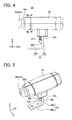
- Fig. 4 is a front face diagram of a height adjustment lever 22.
- Fig. 5 is a perspective diagram of the height adjustment lever 22.
- Fig. 6 is a vertical cross-sectional diagram of the height adjustment lever 22.
- Fig. 7 is a cross-sectional diagram along line VII - VII in Fig. 4 .
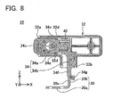
- Fig. 8 is a vertical cross-sectional diagram of the height adjustment lever 22 in a state where a push button 34c is pushed.
- Fig. 9 is a plan diagram of a slit hole 50 in a state where the push button 34c is not pushed.
- Fig. 10 is a plan diagram of the slit hole 50 in a state where the push button 34c is pushed.
- a push mower 10 (or a walk behind mower) according to the embodiment comprises a body 12, a pair of front wheels 14, a rear wheel 16, a handle 18, a blade 20, a height adjustment lever 22, and a grass catcher 24.
- the pair of front wheels 14 is respectively disposed on the left and right-hand sides of a front part of the body 12.
- the pair of front wheels 14 is connected to the body 12 via a swing frame 26 which is shown in Fig. 2 .
- the front wheels 14 are attached to the swing frame 26 by a rotating axle 14a and are able to rotate about the rotating axle 14a.
- the swing frame 26 is attached to the body 12 by a swing axle 26a parallel to the rotating axle 14a, and is able to swing with respect to the body 12 about the swing axle 26a.
- the swing frame 26 is able to swing between the position shown in Fig. 2 and the position shown in Fig. 3 .
- the position of the front wheels 14 with respect to the body 12 in the height direction is changed by swing of the swing frame 26. More specifically, when the swing frame 26 swings, the interval between the ground and the bottom part of the body 12 changes.
- the rear wheel 16 is installed rotatably on a lower rear part of the body 12.
- the blade 20 is attached to a lower part of the body 12.
- the blade 20 is disposed in a position facing the ground.
- the blade 20 rotates about an axis substantially perpendicular to the ground.
- the blade 20 is rotated by a motor (not illustrated) provided inside the body 12.
- the handle 18 has a pair of shafts 18a and 18b, and grip 18c.
- the shafts 18a and 18b extend inclinedly rearwards and upwards from a side face of the body 12.
- the grip 18c is connected to end parts of the shafts 18a and 18b.
- a grass catcher 24 is connected to a rear part of the body 12. The grass catcher 24 collects and holds cut grass.
- the height adjustment lever 22 has a grip 32, a shaft 30 extending from the grip 32, and a lock member 34 attached to the grip 32.
- the shaft 30 is fixed to the swing frame 26.
- the shaft 30 protrudes to the outside of the body 12 via a slit hole 50 formed on a front part of the body 12.
- the grip 32 is fixed to the shaft 30 on the outer side of the body 12.
- the blade 20 When the push mower 10 is used, the blade 20 is rotated by driving a motor. As the user walks while pushing the push mower 10, the blade 20 strikes grass and cuts the grass. The cut grass is conveyed to the grass catcher 24.
- the shaft 30 is constituted by an L-shaped bracket which is formed by bending a metal plate in its thickness direction at a substantially right angle.
- a direction in which a short edge portion 30a of the shaft 30 extends is the X direction
- a direction in which a long edge portion 30b of the shaft 30 extends is the Z direction
- a direction perpendicular to the X direction and the Z direction is the Y direction.
- the short edge portion 30a of the shaft 30 is screw fastened to the swing frame 26.
- the long edge portion 30b of the shaft 30 passes through the slit hole 50 in the body 12 and extends to the outside of the body 12.
- a through hole 30c is formed in the long edge portion 30b.
- the through hole 30c opens to a direction perpendicular to the direction of movement of the height adjustment lever 22.
- the grip 32 is fixed to an end of the long edge portion 30b of the shaft 30.
- the grip 32 has the shape of an elliptical column with curved side faces and extends in the X direction.
- An opening 32a is formed in one end face of the grip 32.
- an opening 32b is formed in a lower part of the approximate center of the grip 32.
- a space which connects the opening 32a to the opening 32b is formed inside the grip 32.
- the lock member 34 has a base portion 34a which extends toward the opening 32a from the approximate center of the grip 32, and an extending portion 34b which extends downwards from the base portion 34a.
- a push button 34c is formed by the portion which protrudes from the opening 32a.
- Fig. 7 shows a cross-sectional diagram along VII - VII line in Fig. 4 .
- a groove 34d is formed in an outer circumferential surface of the base portion 34a.
- a protruding rail 32c is formed on an inner surface of the grip 32.
- the groove 34d and the rail 32c extend in the X direction.
- the groove 34d engages with the rail 32c.
- the lock member 34 is able to slide in the X direction with respect to the grip 32, due the groove 34d being guided by the rail 32c. In other words, the lock member 34 is supported slidably by the grip 32.
- grooves 34e extending in the X direction are formed in an upper part and a lower part of the base portion 34a.
- Convex portions 32d are formed in an upper part and a lower part of an inner surface of the grip 32.
- the convex portions 32d are inserted respectively into the corresponding grooves 34e.
- a spring 40 is disposed beside the base portion 34a. One end of the spring 40 is in contact with the base portion 34a, and the other end of the spring 40 is in contact with a wall face formed in the approximate center of the grip 32.
- the spring 40 biases the lock member 34 toward the opening 32a.
- the lock member 34 is located in a position where the respective convex portions 32d are in contact with end parts of the grooves 34e.
- the spring 40 is compressed and the lock member 34 moves in the X direction (the rightward direction in Fig. 6 ).
- the spring 40 extends and the lock member 34 returns to a position shown in Fig. 6 .
- the extending portion 34b has a first part 34f which extends along the long edge portion 30b from the base portion 34a and a second part 34g which bends from the first part 34f and extends towards the long edge portion 30b.
- the second part 34g is located inside the through hole 30c of the shaft 30.
- the height adjustment lever 22 is installed in a manner that the grip 32 extends in a left/right direction and the push button 34c is positioned on a left-hand side when the push mower 10 is viewed from the front side.
- Fig. 9 shows a slit hole 50 formed in the front part of the body 12.
- the shaft 30 of the height adjustment lever 22 is inserted into the slit hole 50.
- the slit hole 50 has a slit portion 52 extending in a straight line and a plurality of cutaway portions 54 extending in a horizontal direction from the slit portion 52.
- the shaft 30 is positioned inside the slit portion 52.
- the push button 34c When the push button 34c is not pushed, the first part 34f of the lock member 34 is positioned inside a cutaway section 54.
- the push button 34c When the push button 34c is pushed, the first part 34f moves inside the through hole 30c of the shaft 30 (in other words, inside the slit portion 52), as shown in Fig. 10 .
- the user grips the grip 32 of the height adjustment lever 22.
- the user then pushes the push button 34c with a finger of the hand gripping the grip 32.
- the lock member 34 slides and, as shown in Fig. 10 , the first part 34f moves inside the slit portion 52 from the cutaway section 54 (in other words, inside the through hole 30c of the shaft 30).
- the shaft 30 becomes movable along the slit portion 52.
- the height adjustment lever 22 becomes movable along the slit portion 52.
- the user moves the height adjustment lever 22 along the slit portion 52. Consequently, the swing frame 26 swings and the height of the blade 20 from the ground (in other words, the cutting height) changes.
- the user moves the height adjustment lever 22 to a position where the desired cutting height is obtained, the user then releases the push button 34c. In so doing, the first part 34f of the lock member 34 engages with the corresponding cutaway portion 54. Due to this, the movement of the height adjustment lever 22 is inhibited and the height of the blade 20 is fixed. By the procedure described above, the user is able to adjust the cutting height.
- the height adjustment lever 22 has a lock member 34 which is separate from the grip 32 and moves relative to the grip 32. Therefore, the user is able to unlock the height adjustment lever 22 by manipulating the lock member 34 (in other words, the push button 34c) with a finger of the hand gripping the grip 32. Since the operating section for unlocking the height adjustment lever 22 (in other words, the push button 34c) and the manipulating section for moving the entirety of height adjustment lever 22 (in other words, the grip 32) are provided separately, then there is no need to perform a complicated movement of the grip 32 itself. The user is able to change the cutting height simply by moving the grip 32 in a straight line along the slit portion 52, while pushing the push button 34c. Consequently, the push mower 10 has good operability for changing the cutting height.
- the user in a composition just like a conventional technique where the grip is moved relative to the main body in order to release the lock, the user must support the main body in order to prevent the main body from moving with the grip. Furthermore, if the height adjustment lever is locked strongly, then the user must apply a strong force to the grip, but since the main body moves, then it may be difficult to release the lock.
- the push button 34c is provided in the grip 32, as in the present embodiment, it is possible to push the push button 34c by the hand gripping the grip 32 while supporting the grip 32 with the hand, and therefore the body 12 itself is not liable to move.
- the second part 34g of the lock member 34 which is at the end side of the extending portion 34b from the first part 34f is inserted into the through hole 30c of the shaft 30.
- the second part 34g contacts the inner surface of the through hole 30c of the shaft 30, and the second part 34g is supported by the inner surface of the through hole 30c.
- the base side of the extending portion 34b of the lock member 34 is supported by the base portion 34a, and the end side of the extending portion 34b is supported by the shaft 30. Consequently, since the end side and the base side of the extending portion 34b are supported, the extending portion 34b is not liable to break even if a strong force is applied to the first part 34f.
- the push mower 10 is composed in a manner that the second part 34g makes contact with and is supported by the shaft 30, only when a strong force is applied to the first part 34f.
- the second part 34g may also be supported by the shaft 30 at all times, in a manner which does not impede the movement of the lock member 34.
- the lock member 34 slides by the groove 34d formed in the lock member 34 being guided by the rail 32c formed in the inner surface of the grip 32. Consequently, it is possible to slide the lock member 34 smoothly. It is also possible to form a groove in the inner surface of the grip and to form a rail engaging that groove in the lock member.
- the push button 34c is positioned on the left side of the grip 32 when the push mower 10 is viewed from the front.
- a right-handed user can manipulate the height adjustment lever 22 easily from the front side.
- the push button 34c should be positioned on the right side viewed from the front. Consequently, it is also possible to compose the height adjustment lever 22 so that the fitting orientation can be changed.
Landscapes
- Life Sciences & Earth Sciences (AREA)
- Environmental Sciences (AREA)
- Harvester Elements (AREA)
Abstract
Description
- The present Application relates to a push mower.
- Japanese Patent Application Publication No.
11-103634 - When adjusting the cutting height of the push mower, the user rotates the grip in the one direction to unlock the height adjustment lever. Consequently, the entirety of the height adjustment lever becomes movable with respect to the main body. The user then grips the grip and moves the entirety of the height adjustment lever with respect to the main body. In so doing, a height of the blade from the ground changes based on the movement of the height adjustment lever. In other words, the cutting height changes. When the height adjustment lever has been moved to a position where a desired cutting height is obtained, the user rotates the grip in the opposite direction and locks the height adjustment lever. In accordance with this, the cutting height is fixed.
- As described above, when adjusting the cutting height by the height adjustment lever in the push mower of Japanese Patent Application Publication No.
11-103634 - A push mower disclosed in this specification comprises a main body, a blade, a height adjustment lever, and a height adjustment mechanism. The main body is configured to move along a ground. The blade is attached to the main body. The height adjustment lever is attached to the main body. The height adjustment mechanism is configured to change a height of the blade above the ground based on a position of the height adjustment lever. The height adjustment lever comprises a pillar protruding from the main body, a grip fixed to the pillar, and a lock member attached to the grip and configured to move with respect to the grip between a lock position and an unlock position. A movement of the height adjustment lever is inhibited when the lock member is at the lock position, and the movement of the height adjustment lever is allowed when the lock member is at the unlock position.
- When adjusting the cutting height in this push mower, the user firstly grips the grip of the height adjustment lever and moves the lock member to the unlock position by manipulating the lock member with a finger. Thereupon, the user changes the height of the blade (in other words, the cutting height) by gripping the grip and manipulating the height adjustment lever. When the height adjustment lever has been moved to a position where a desired cutting height is obtained, the user moves the lock member to the lock position and fixes the cutting height. Consequently, in this push mower, since the lock member which is separated from the grip is attached on the grip, then the user is able to manipulate the lock member with a finger while gripping the grip. More specifically, there is no need to move the grip itself for the purpose of unlocking. Since there is no need to move the grip for the purpose of unlocking, then the height adjustment lever has good operability.
- In the push mower described above, the lock member may preferably comprise a base portion supported by the grip, and an extending portion extending from the base portion. An engaging part of the extending portion may engage with the main body when the lock member is at the lock position.
- In the push mower described above, the base portion may be within the grip. The extending portion may extend from the base portion to an outside of the grip into the main body.
- In the push mower described above, an end part of the extending portion, which is at an end side of the extending portion from the engaging part, may be supported by the pillar when the height adjustment lever is manipulated in a state which the lock member is at the lock position.
- In this push mower, when the lock member is in the lock position, the movement of the height adjustment lever is inhibited due to the engaging part of the extending portion engaging with the main body. Therefore, if a user attempts to move the height adjustment lever forcibly when the lock member is in the lock position, a strong force is applied to the extending portion. However, the end part of the extending portion, which is at the end side from the engaging part is supported by the pillar of the height adjustment lever when the height adjustment lever is manipulated while the lock member is in the lock position. Furthermore, a base side of the extending portion is connected to the base portion. In other words, the end side and the base side of the extending portion are supported by the base portion and the pillar. Therefore, the extending portion has high strength.
- In the push mowers of which the lock member comprises the base portion and the extending portion, the push mower can be configured as follows. That is, a hole may be formed on the pillar. The end part of the extending portion, which is at the end side of the extending portion from the engaging part, is in the hole when the lock member is at the lock position. The hole may open to a direction perpendicular to a direction of the movement of the height adjustment lever.
- In this configuration, if force is applied to the extending portion when the lock member is in the lock position, then the end part of the extending portion is supported by the inner surface of the hole on the pillar. In other words, the extending portion is supported at either end. By this configuration, it is possible to improve the strength of the extending portion.
- In the push mowers of which the hole is formed on the pillar, the hole may open to a direction perpendicular to a direction of the movement of the height adjustment lever.
- The push mowers described above may preferably further comprise a spring biasing the lock member to the lock position. The lock member may comprise a button portion configured to protrude from the grip when the lock member is at the lock position. The lock member may move to the unlock position when the button portion is pushed.
- In this configuration, if the user pushes the button portion, the height adjustment lever is unlocked. Furthermore, if the user releases the button portion, the lock member is moved to the lock position by the spring and the height adjustment lever is locked. Due to this, it is possible to switch locking easily by manipulating the button portion.
- In the push mowers described above, a rail section or groove section which guides a lock member slidably may preferably be formed in a grip of a height adjustment lever.
-
Fig. 1 is a perspective diagram of apush mower 10. -
Fig. 2 is a vertical cross-sectional diagram of apush mower 10 set to a low cutting height. -
Fig. 3 is a vertical cross-sectional diagram of apush mower 10 set to a high cutting height. -
Fig. 4 is a front face diagram of aheight adjustment lever 22. -
Fig. 5 is a perspective diagram of theheight adjustment lever 22. -
Fig. 6 is a vertical cross-sectional diagram of theheight adjustment lever 22. -
Fig. 7 is a cross-sectional diagram along line VII - VII inFig. 4 . -
Fig. 8 is a vertical cross-sectional diagram of theheight adjustment lever 22 in a state where apush button 34c is pushed. -
Fig. 9 is a plan diagram of aslit hole 50 in a state where thepush button 34c is not pushed. -
Fig. 10 is a plan diagram of theslit hole 50 in a state where thepush button 34c is pushed. - A push mower according to an embodiment is now described. As shown in
Figs. 1 and2 , a push mower 10 (or a walk behind mower) according to the embodiment comprises abody 12, a pair offront wheels 14, arear wheel 16, ahandle 18, ablade 20, aheight adjustment lever 22, and agrass catcher 24. - The pair of
front wheels 14 is respectively disposed on the left and right-hand sides of a front part of thebody 12. The pair offront wheels 14 is connected to thebody 12 via aswing frame 26 which is shown inFig. 2 . Thefront wheels 14 are attached to theswing frame 26 by arotating axle 14a and are able to rotate about therotating axle 14a. Theswing frame 26 is attached to thebody 12 by aswing axle 26a parallel to therotating axle 14a, and is able to swing with respect to thebody 12 about theswing axle 26a. Theswing frame 26 is able to swing between the position shown inFig. 2 and the position shown inFig. 3 . As shown inFigs. 2 and3 , the position of thefront wheels 14 with respect to thebody 12 in the height direction is changed by swing of theswing frame 26. More specifically, when theswing frame 26 swings, the interval between the ground and the bottom part of thebody 12 changes. - The
rear wheel 16 is installed rotatably on a lower rear part of thebody 12. - The
blade 20 is attached to a lower part of thebody 12. Theblade 20 is disposed in a position facing the ground. Theblade 20 rotates about an axis substantially perpendicular to the ground. Theblade 20 is rotated by a motor (not illustrated) provided inside thebody 12. When theswing frame 26 swings as described above, the interval between the ground and theblade 20 changes. Consequently, the height at which theblade 20 cuts grass (in other words, the cutting height) changes. - The
handle 18 has a pair ofshafts grip 18c. Theshafts body 12. Thegrip 18c is connected to end parts of theshafts - A
grass catcher 24 is connected to a rear part of thebody 12. Thegrass catcher 24 collects and holds cut grass. - The
height adjustment lever 22 has agrip 32, ashaft 30 extending from thegrip 32, and alock member 34 attached to thegrip 32. Theshaft 30 is fixed to theswing frame 26. Theshaft 30 protrudes to the outside of thebody 12 via aslit hole 50 formed on a front part of thebody 12. Thegrip 32 is fixed to theshaft 30 on the outer side of thebody 12. By manipulating theheight adjustment lever 22, it is possible to swing theswing frame 26 between the position shown inFig. 2 and the position shown inFig. 3 . More specifically, it is possible to adjust the grass cutting height by manipulating theheight adjustment lever 22. - When the
push mower 10 is used, theblade 20 is rotated by driving a motor. As the user walks while pushing thepush mower 10, theblade 20 strikes grass and cuts the grass. The cut grass is conveyed to thegrass catcher 24. - Next, a structure of the
height adjustment lever 22 will be described in detail. As shown inFigs. 4 to 6 , theshaft 30 is constituted by an L-shaped bracket which is formed by bending a metal plate in its thickness direction at a substantially right angle. Below, a direction in which ashort edge portion 30a of theshaft 30 extends is the X direction, a direction in which along edge portion 30b of theshaft 30 extends is the Z direction, and a direction perpendicular to the X direction and the Z direction is the Y direction. Theshort edge portion 30a of theshaft 30 is screw fastened to theswing frame 26. Thelong edge portion 30b of theshaft 30 passes through theslit hole 50 in thebody 12 and extends to the outside of thebody 12. A throughhole 30c is formed in thelong edge portion 30b. The throughhole 30c opens to a direction perpendicular to the direction of movement of theheight adjustment lever 22. - The
grip 32 is fixed to an end of thelong edge portion 30b of theshaft 30. Thegrip 32 has the shape of an elliptical column with curved side faces and extends in the X direction. Anopening 32a is formed in one end face of thegrip 32. Furthermore, anopening 32b is formed in a lower part of the approximate center of thegrip 32. A space which connects theopening 32a to theopening 32b is formed inside thegrip 32. - As shown in
Fig. 6 , a major part of thelock member 34 is accommodated in the space inside thegrip 32. Thelock member 34 has abase portion 34a which extends toward theopening 32a from the approximate center of thegrip 32, and an extendingportion 34b which extends downwards from thebase portion 34a. - One end part of the
base portion 34a protrudes to the outside of thegrip 32 from theopening 32a. Apush button 34c is formed by the portion which protrudes from theopening 32a. -
Fig. 7 shows a cross-sectional diagram along VII - VII line inFig. 4 . As shown inFig. 7 , agroove 34d is formed in an outer circumferential surface of thebase portion 34a. Furthermore, a protrudingrail 32c is formed on an inner surface of thegrip 32. Thegroove 34d and therail 32c extend in the X direction. Thegroove 34d engages with therail 32c. Thelock member 34 is able to slide in the X direction with respect to thegrip 32, due thegroove 34d being guided by therail 32c. In other words, thelock member 34 is supported slidably by thegrip 32. - As shown in
Fig. 6 ,grooves 34e extending in the X direction are formed in an upper part and a lower part of thebase portion 34a.Convex portions 32d are formed in an upper part and a lower part of an inner surface of thegrip 32. Theconvex portions 32d are inserted respectively into thecorresponding grooves 34e. Aspring 40 is disposed beside thebase portion 34a. One end of thespring 40 is in contact with thebase portion 34a, and the other end of thespring 40 is in contact with a wall face formed in the approximate center of thegrip 32. Thespring 40 biases thelock member 34 toward theopening 32a. By thespring 40, thelock member 34 is located in a position where the respectiveconvex portions 32d are in contact with end parts of thegrooves 34e. If the user pushes thepush button 34c, thespring 40 is compressed and thelock member 34 moves in the X direction (the rightward direction inFig. 6 ). When the user releases thepush button 34c, thespring 40 extends and thelock member 34 returns to a position shown inFig. 6 . - The extending
portion 34b has afirst part 34f which extends along thelong edge portion 30b from thebase portion 34a and asecond part 34g which bends from thefirst part 34f and extends towards thelong edge portion 30b. In a state where thepush button 34c is not being pushed as shown inFig. 6 , thesecond part 34g is located inside the throughhole 30c of theshaft 30. When thepush button 34c is pushed, the entirety of thefirst part 34f moves inside the hole as shown inFig. 8 . - As shown in
Figs. 1 and2 , theheight adjustment lever 22 is installed in a manner that thegrip 32 extends in a left/right direction and thepush button 34c is positioned on a left-hand side when thepush mower 10 is viewed from the front side. -
Fig. 9 shows aslit hole 50 formed in the front part of thebody 12. As stated above, theshaft 30 of theheight adjustment lever 22 is inserted into theslit hole 50. As shown inFig. 9 , theslit hole 50 has aslit portion 52 extending in a straight line and a plurality ofcutaway portions 54 extending in a horizontal direction from theslit portion 52. - The
shaft 30 is positioned inside theslit portion 52. When thepush button 34c is not pushed, thefirst part 34f of thelock member 34 is positioned inside acutaway section 54. When thepush button 34c is pushed, thefirst part 34f moves inside the throughhole 30c of the shaft 30 (in other words, inside the slit portion 52), as shown inFig. 10 . - Next, the method of adjusting the cutting height will be described. When the
push button 34c is not pushed, as shown inFig. 9 , thefirst part 34f of thelock member 34 is positioned inside acutaway section 54. Since thefirst part 34f is engaged with acutaway section 54, theshaft 30 cannot move inside theslit portion 52. In other words, movement of theheight adjustment lever 22 is inhibited by thefirst part 34f engaging with thecutaway section 54. - When adjusting the cutting height, the user grips the
grip 32 of theheight adjustment lever 22. The user then pushes thepush button 34c with a finger of the hand gripping thegrip 32. In so doing, thelock member 34 slides and, as shown inFig. 10 , thefirst part 34f moves inside theslit portion 52 from the cutaway section 54 (in other words, inside the throughhole 30c of the shaft 30). By this means, theshaft 30 becomes movable along theslit portion 52. In other words, theheight adjustment lever 22 becomes movable along theslit portion 52. Next, the user moves theheight adjustment lever 22 along theslit portion 52. Consequently, theswing frame 26 swings and the height of theblade 20 from the ground (in other words, the cutting height) changes. When the user moves theheight adjustment lever 22 to a position where the desired cutting height is obtained, the user then releases thepush button 34c. In so doing, thefirst part 34f of thelock member 34 engages with the correspondingcutaway portion 54. Due to this, the movement of theheight adjustment lever 22 is inhibited and the height of theblade 20 is fixed. By the procedure described above, the user is able to adjust the cutting height. - As described above, in the
push mower 10, theheight adjustment lever 22 has alock member 34 which is separate from thegrip 32 and moves relative to thegrip 32. Therefore, the user is able to unlock theheight adjustment lever 22 by manipulating the lock member 34 (in other words, thepush button 34c) with a finger of the hand gripping thegrip 32. Since the operating section for unlocking the height adjustment lever 22 (in other words, thepush button 34c) and the manipulating section for moving the entirety of height adjustment lever 22 (in other words, the grip 32) are provided separately, then there is no need to perform a complicated movement of thegrip 32 itself. The user is able to change the cutting height simply by moving thegrip 32 in a straight line along theslit portion 52, while pushing thepush button 34c. Consequently, thepush mower 10 has good operability for changing the cutting height. - Furthermore, in a composition just like a conventional technique where the grip is moved relative to the main body in order to release the lock, the user must support the main body in order to prevent the main body from moving with the grip. Furthermore, if the height adjustment lever is locked strongly, then the user must apply a strong force to the grip, but since the main body moves, then it may be difficult to release the lock. On the other hand, if the
push button 34c is provided in thegrip 32, as in the present embodiment, it is possible to push thepush button 34c by the hand gripping thegrip 32 while supporting thegrip 32 with the hand, and therefore thebody 12 itself is not liable to move. Consequently, even if the elastic force of thespring 40 biasing thelock member 34 is raised and theheight adjustment lever 22 is locked strongly, a situation is not liable to occur where thebody 12 moves and it is difficult to release the lock. According to the composition of the present embodiment, it is possible to manipulate theheight adjustment lever 22 without supporting thebody 12, or by just supporting thebody 12 lightly. - Furthermore, if the user attempts to move the
height adjustment lever 22 in a state where theheight adjustment lever 22 is locked, then a strong force is applied to thefirst part 34f of thelock member 34 which is engaged with acutaway section 54. Furthermore, if a strong force is applied to the front wheels 14 (for example, if thepush mower 10 gets over a level difference, or the like), in a state where theheight adjustment lever 22 is locked, then a strong force is also applied to thefirst part 34f of thelock member 34. In thepush mower 10 according to the present embodiment, thesecond part 34g of thelock member 34, which is at the end side of the extendingportion 34b from thefirst part 34f is inserted into the throughhole 30c of theshaft 30. Therefore, if a strong force is applied to thefirst part 34f, thesecond part 34g contacts the inner surface of the throughhole 30c of theshaft 30, and thesecond part 34g is supported by the inner surface of the throughhole 30c. In other words, when a strong force is applied, the base side of the extendingportion 34b of thelock member 34 is supported by thebase portion 34a, and the end side of the extendingportion 34b is supported by theshaft 30. Consequently, since the end side and the base side of the extendingportion 34b are supported, the extendingportion 34b is not liable to break even if a strong force is applied to thefirst part 34f. - The
push mower 10 according to the present embodiment is composed in a manner that thesecond part 34g makes contact with and is supported by theshaft 30, only when a strong force is applied to thefirst part 34f. However, thesecond part 34g may also be supported by theshaft 30 at all times, in a manner which does not impede the movement of thelock member 34. - Furthermore, in the
push mower 10 according to the present embodiment, thelock member 34 slides by thegroove 34d formed in thelock member 34 being guided by therail 32c formed in the inner surface of thegrip 32. Consequently, it is possible to slide thelock member 34 smoothly. It is also possible to form a groove in the inner surface of the grip and to form a rail engaging that groove in the lock member. - Furthermore, in the
push mower 10 according to the present embodiment, thepush button 34c is positioned on the left side of thegrip 32 when thepush mower 10 is viewed from the front. In this case, a right-handed user can manipulate theheight adjustment lever 22 easily from the front side. On the other hand, if theheight adjustment lever 22 is to be manipulated from thehandle 18 side, then thepush button 34c should be positioned on the right side viewed from the front. Consequently, it is also possible to compose theheight adjustment lever 22 so that the fitting orientation can be changed. - It is explicitly stated that all features disclosed in the description and/or the claims are intended to be disclosed separately and independently from each other for the purpose of original disclosure as well as for the purpose of restricting the claimed invention independent of the composition of the features in the embodiments and/or the claims. It is explicitly stated that all value ranges or indications of groups of entities disclose every possible intermediate value or intermediate entity for the purpose of original disclosure as well as for the purpose of restricting the claimed invention, in particular as limits of value ranges.
Claims (7)
- A push mower (10) comprising:a main body (12) configured to move along a ground;a blade (20) attached to the main body (12);a height adjustment lever (22) attached to the main body (12); anda height adjustment mechanism (14, 14a, 26, 26a) configured to change a height of the blade (20) from the ground based on a position of the height adjustment lever (22),whereinthe height adjustment lever (22) comprises:a pillar (30b) protruding from the main body (12);a grip (32) fixed to the pillar (30b); anda lock member (34) attached to the grip (32) and configured to move with respect to the grip (32) between a lock position and an unlock position, anda movement of the height adjustment lever (22) is inhibited when the lock member (34) is at the lock position, and the movement of the height adjustment lever (22) is allowed when the lock member (34) is at the unlock position.
- The push mower (10) of claim 1, wherein the lock member (34) comprises:a base portion (34a) supported by the grip (32); andan extending portion (34b) extending from the base portion (34a), wherein an engaging part (34f) of the extending portion (34b) engages with the main body (12) when the lock member (34) is at the lock position.
- The push mower (10) of claim 2, wherein
the base portion (34a) is within the grip (32); and
the extending portion (34b) extends from the base portion (34a) to an outside of the grip (32) into the main body (12). - The push mower (10) of claim 2 or 3, wherein
an end part (34g) of the extending portion (34b), which is at an end side of the extending portion (34b) from the engaging part (34f), is supported by the pillar (30b) when the height adjustment lever (22) is manipulated in a state which the lock member (34) is at the lock position. - The push mower (10) of claim 2,3 or 4, wherein
a hole (30c) is formed on the pillar (30b), and
an end part (34g) of the extending portion (34b), which is at an end side of the extending portion (34b) from the engaging part (34f), is in the hole (30c) when the lock member (34) is at the lock position. - The push mower (10) of claim 5, wherein the hole (30c) opens to a direction (X) perpendicular to a direction of the movement of the height adjustment lever (22).
- The push mower (10) of any one of claims 1-6, further comprising a spring (40) biasing the lock member (34) to the lock position,
wherein
the lock member (34) comprises a button portion (34c) configured to protrude from the grip 32 when the lock member (34) is at the lock position, and
the lock member (34) moves to the unlock position when the button portion (34c) is pushed.
Applications Claiming Priority (1)
| Application Number | Priority Date | Filing Date | Title |
|---|---|---|---|
| JP2010138083A JP5620160B2 (en) | 2010-06-17 | 2010-06-17 | Hand-held lawn mower |
Publications (2)
| Publication Number | Publication Date |
|---|---|
| EP2397025A1 true EP2397025A1 (en) | 2011-12-21 |
| EP2397025B1 EP2397025B1 (en) | 2013-11-13 |
Family
ID=44534916
Family Applications (1)
| Application Number | Title | Priority Date | Filing Date |
|---|---|---|---|
| EP11168920.4A Not-in-force EP2397025B1 (en) | 2010-06-17 | 2011-06-07 | Push mower |
Country Status (4)
| Country | Link |
|---|---|
| US (1) | US8347593B2 (en) |
| EP (1) | EP2397025B1 (en) |
| JP (1) | JP5620160B2 (en) |
| CN (1) | CN102282962B (en) |
Cited By (1)
| Publication number | Priority date | Publication date | Assignee | Title |
|---|---|---|---|---|
| ITUB20154155A1 (en) * | 2015-10-02 | 2017-04-02 | Stiga S P A In Breve Anche St S P A | Lifting mechanism for a lawn mower. |
Families Citing this family (6)
| Publication number | Priority date | Publication date | Assignee | Title |
|---|---|---|---|---|
| US9635809B2 (en) * | 2014-06-10 | 2017-05-02 | Textron Inc. | Electronic control for a grass cutting reel assembly of a lawn-care vehicle |
| US9439352B2 (en) | 2015-02-02 | 2016-09-13 | Husqvarna Ab | Handle height adjuster for walk behind mower |
| DE102015222376A1 (en) * | 2015-11-13 | 2017-05-18 | Robert Bosch Gmbh | Autonomous working device |
| JP6938133B2 (en) * | 2016-11-08 | 2021-09-22 | 株式会社マキタ | Lawn mower |
| US11206759B2 (en) | 2017-11-21 | 2021-12-28 | The Toro Company | Mower quick height of cut adjustment |
| JP7570277B2 (en) | 2021-04-30 | 2024-10-21 | 株式会社マキタ | Work equipment |
Citations (5)
| Publication number | Priority date | Publication date | Assignee | Title |
|---|---|---|---|---|
| US3677574A (en) * | 1970-10-09 | 1972-07-18 | Lawrence Cyr | Means for adjusting heights of cut in power mower |
| EP0766911A1 (en) * | 1995-10-03 | 1997-04-09 | Electrolux Outdoor Products Limited | Cutting-height adjustment for lawnmower |
| JPH11103634A (en) | 1997-09-29 | 1999-04-20 | Makita Corp | Trimming height regulatory mechanism in lawn mower |
| EP1637023A2 (en) * | 2004-09-16 | 2006-03-22 | Viking GmbH | hight adjustment for rolling working implement |
| DE202008002831U1 (en) * | 2008-02-28 | 2008-05-08 | Viking Gmbh | Adjustment lever for height adjustment of a mower deck |
Family Cites Families (14)
| Publication number | Priority date | Publication date | Assignee | Title |
|---|---|---|---|---|
| US2848859A (en) * | 1957-04-03 | 1958-08-26 | Huffman Mfg Company | Lawn mower with adjustable wheel mounting assembly |
| US3357715A (en) * | 1966-02-10 | 1967-12-12 | M T & D Company | Mower having wheel adjustable means |
| DE2604609C3 (en) | 1976-02-06 | 1981-10-01 | Fritz Roth Kg, 7000 Stuttgart | mowing machine |
| US4321784A (en) * | 1980-07-15 | 1982-03-30 | The Toro Company | Height of cut adjustment |
| JPS6094039U (en) * | 1983-11-30 | 1985-06-27 | 本田技研工業株式会社 | Cutting height adjustment display device for riding lawn mowers |
| JPS61146110A (en) * | 1984-12-20 | 1986-07-03 | 株式会社共立 | Lawn mower |
| US4785612A (en) * | 1987-07-24 | 1988-11-22 | Yamaha Hatsudoki Kabushiki Kaisha | Walk-behind lawn mower |
| US4905463A (en) * | 1988-12-02 | 1990-03-06 | Canadiana Outdoor Products Inc. | Single action wheel height adjuster |
| US5230208A (en) * | 1990-06-01 | 1993-07-27 | Black & Decker Inc. | Lawn mower height-adjust systems |
| JPH0546240U (en) * | 1991-11-26 | 1993-06-22 | 松下電工株式会社 | lawn mower |
| JP2531754Y2 (en) | 1991-11-26 | 1997-04-09 | 松下電工株式会社 | lawn mower |
| US5259175A (en) * | 1992-11-24 | 1993-11-09 | The Toro Company | Lawn mower height of cut adjustment system |
| US5526633A (en) * | 1994-08-12 | 1996-06-18 | Black & Decker Inc. | Lawn mower having improved deck height adjustment mechanism |
| JP3157848U (en) * | 2009-12-17 | 2010-03-04 | 株式会社筑水キャニコム | Cutting blade lifting device |
-
2010
- 2010-06-17 JP JP2010138083A patent/JP5620160B2/en not_active Expired - Fee Related
-
2011
- 2011-06-07 EP EP11168920.4A patent/EP2397025B1/en not_active Not-in-force
- 2011-06-07 US US13/154,950 patent/US8347593B2/en not_active Expired - Fee Related
- 2011-06-15 CN CN201110165908.4A patent/CN102282962B/en not_active Expired - Fee Related
Patent Citations (5)
| Publication number | Priority date | Publication date | Assignee | Title |
|---|---|---|---|---|
| US3677574A (en) * | 1970-10-09 | 1972-07-18 | Lawrence Cyr | Means for adjusting heights of cut in power mower |
| EP0766911A1 (en) * | 1995-10-03 | 1997-04-09 | Electrolux Outdoor Products Limited | Cutting-height adjustment for lawnmower |
| JPH11103634A (en) | 1997-09-29 | 1999-04-20 | Makita Corp | Trimming height regulatory mechanism in lawn mower |
| EP1637023A2 (en) * | 2004-09-16 | 2006-03-22 | Viking GmbH | hight adjustment for rolling working implement |
| DE202008002831U1 (en) * | 2008-02-28 | 2008-05-08 | Viking Gmbh | Adjustment lever for height adjustment of a mower deck |
Cited By (1)
| Publication number | Priority date | Publication date | Assignee | Title |
|---|---|---|---|---|
| ITUB20154155A1 (en) * | 2015-10-02 | 2017-04-02 | Stiga S P A In Breve Anche St S P A | Lifting mechanism for a lawn mower. |
Also Published As
| Publication number | Publication date |
|---|---|
| US20110308219A1 (en) | 2011-12-22 |
| EP2397025B1 (en) | 2013-11-13 |
| US8347593B2 (en) | 2013-01-08 |
| CN102282962A (en) | 2011-12-21 |
| JP2012000051A (en) | 2012-01-05 |
| JP5620160B2 (en) | 2014-11-05 |
| CN102282962B (en) | 2015-06-17 |
Similar Documents
| Publication | Publication Date | Title |
|---|---|---|
| EP2397025B1 (en) | Push mower | |
| AU2008229792B2 (en) | A power tool | |
| US8413338B2 (en) | Folding knife with safety and wedge lock | |
| EP0941797B1 (en) | Sliding mitre saw | |
| US9511428B2 (en) | Bevel lock assembly for miter saws | |
| JP5530780B2 (en) | Walking lawn mower | |
| EP2368659B1 (en) | Pivoting blade retainer | |
| EP2673123B1 (en) | Powered circular saw and method of use thereof | |
| EP2039455B1 (en) | Adjustable and removable keel assembly and blade guide for a jigsaw | |
| EP2377636B1 (en) | Cutting device | |
| WO2006113200A1 (en) | Releasable blade locking mechanism for utility knife | |
| EP1033211B1 (en) | Locking arrangement for table saw guard | |
| CN100381038C (en) | Pivoting handle assembly for power tool | |
| JP6976187B2 (en) | Electric tool | |
| EP2436494B1 (en) | Cutting machine with a safety cover | |
| EP1894686B1 (en) | Fine adjustment mechanism for precision miter cuts | |
| US20060288592A1 (en) | Reciprocating tool | |
| EP2218564B1 (en) | Tile cutter with height-adjustable tool carrier | |
| EP3217412B1 (en) | Switch for a hand-held power tool | |
| EP1525938A1 (en) | Miter saw | |
| US7263910B2 (en) | Tilt control lever assembly for steering column | |
| KR101543045B1 (en) | Outside handle for vehicle | |
| KR101476304B1 (en) | tilt lever for tilting apparatus of steering column | |
| WO2015175461A1 (en) | Knife blade opening assist mechanism | |
| EP2554313B1 (en) | Lock for power tool |
Legal Events
| Date | Code | Title | Description |
|---|---|---|---|
| AK | Designated contracting states |
Kind code of ref document: A1 Designated state(s): AL AT BE BG CH CY CZ DE DK EE ES FI FR GB GR HR HU IE IS IT LI LT LU LV MC MK MT NL NO PL PT RO RS SE SI SK SM TR |
|
| AX | Request for extension of the european patent |
Extension state: BA ME |
|
| PUAI | Public reference made under article 153(3) epc to a published international application that has entered the european phase |
Free format text: ORIGINAL CODE: 0009012 |
|
| 17P | Request for examination filed |
Effective date: 20120601 |
|
| 17Q | First examination report despatched |
Effective date: 20120809 |
|
| GRAP | Despatch of communication of intention to grant a patent |
Free format text: ORIGINAL CODE: EPIDOSNIGR1 |
|
| INTG | Intention to grant announced |
Effective date: 20130717 |
|
| GRAS | Grant fee paid |
Free format text: ORIGINAL CODE: EPIDOSNIGR3 |
|
| GRAA | (expected) grant |
Free format text: ORIGINAL CODE: 0009210 |
|
| RIN1 | Information on inventor provided before grant (corrected) |
Inventor name: IFUKU, YASUO Inventor name: ITO, RYOSUKE |
|
| AK | Designated contracting states |
Kind code of ref document: B1 Designated state(s): AL AT BE BG CH CY CZ DE DK EE ES FI FR GB GR HR HU IE IS IT LI LT LU LV MC MK MT NL NO PL PT RO RS SE SI SK SM TR |
|
| REG | Reference to a national code |
Ref country code: GB Ref legal event code: FG4D |
|
| REG | Reference to a national code |
Ref country code: CH Ref legal event code: EP |
|
| REG | Reference to a national code |
Ref country code: AT Ref legal event code: REF Ref document number: 640149 Country of ref document: AT Kind code of ref document: T Effective date: 20131215 |
|
| REG | Reference to a national code |
Ref country code: IE Ref legal event code: FG4D |
|
| REG | Reference to a national code |
Ref country code: DE Ref legal event code: R096 Ref document number: 602011003632 Country of ref document: DE Effective date: 20140109 |
|
| REG | Reference to a national code |
Ref country code: NL Ref legal event code: VDEP Effective date: 20131113 |
|
| REG | Reference to a national code |
Ref country code: AT Ref legal event code: MK05 Ref document number: 640149 Country of ref document: AT Kind code of ref document: T Effective date: 20131113 |
|
| REG | Reference to a national code |
Ref country code: LT Ref legal event code: MG4D |
|
| PG25 | Lapsed in a contracting state [announced via postgrant information from national office to epo] |
Ref country code: IS Free format text: LAPSE BECAUSE OF FAILURE TO SUBMIT A TRANSLATION OF THE DESCRIPTION OR TO PAY THE FEE WITHIN THE PRESCRIBED TIME-LIMIT Effective date: 20140313 Ref country code: FI Free format text: LAPSE BECAUSE OF FAILURE TO SUBMIT A TRANSLATION OF THE DESCRIPTION OR TO PAY THE FEE WITHIN THE PRESCRIBED TIME-LIMIT Effective date: 20131113 Ref country code: LT Free format text: LAPSE BECAUSE OF FAILURE TO SUBMIT A TRANSLATION OF THE DESCRIPTION OR TO PAY THE FEE WITHIN THE PRESCRIBED TIME-LIMIT Effective date: 20131113 Ref country code: NO Free format text: LAPSE BECAUSE OF FAILURE TO SUBMIT A TRANSLATION OF THE DESCRIPTION OR TO PAY THE FEE WITHIN THE PRESCRIBED TIME-LIMIT Effective date: 20140213 Ref country code: SE Free format text: LAPSE BECAUSE OF FAILURE TO SUBMIT A TRANSLATION OF THE DESCRIPTION OR TO PAY THE FEE WITHIN THE PRESCRIBED TIME-LIMIT Effective date: 20131113 Ref country code: HR Free format text: LAPSE BECAUSE OF FAILURE TO SUBMIT A TRANSLATION OF THE DESCRIPTION OR TO PAY THE FEE WITHIN THE PRESCRIBED TIME-LIMIT Effective date: 20131113 Ref country code: NL Free format text: LAPSE BECAUSE OF FAILURE TO SUBMIT A TRANSLATION OF THE DESCRIPTION OR TO PAY THE FEE WITHIN THE PRESCRIBED TIME-LIMIT Effective date: 20131113 |
|
| PG25 | Lapsed in a contracting state [announced via postgrant information from national office to epo] |
Ref country code: AT Free format text: LAPSE BECAUSE OF FAILURE TO SUBMIT A TRANSLATION OF THE DESCRIPTION OR TO PAY THE FEE WITHIN THE PRESCRIBED TIME-LIMIT Effective date: 20131113 Ref country code: LV Free format text: LAPSE BECAUSE OF FAILURE TO SUBMIT A TRANSLATION OF THE DESCRIPTION OR TO PAY THE FEE WITHIN THE PRESCRIBED TIME-LIMIT Effective date: 20131113 Ref country code: BE Free format text: LAPSE BECAUSE OF FAILURE TO SUBMIT A TRANSLATION OF THE DESCRIPTION OR TO PAY THE FEE WITHIN THE PRESCRIBED TIME-LIMIT Effective date: 20131113 Ref country code: CY Free format text: LAPSE BECAUSE OF FAILURE TO SUBMIT A TRANSLATION OF THE DESCRIPTION OR TO PAY THE FEE WITHIN THE PRESCRIBED TIME-LIMIT Effective date: 20131113 Ref country code: RS Free format text: LAPSE BECAUSE OF FAILURE TO SUBMIT A TRANSLATION OF THE DESCRIPTION OR TO PAY THE FEE WITHIN THE PRESCRIBED TIME-LIMIT Effective date: 20131113 Ref country code: ES Free format text: LAPSE BECAUSE OF FAILURE TO SUBMIT A TRANSLATION OF THE DESCRIPTION OR TO PAY THE FEE WITHIN THE PRESCRIBED TIME-LIMIT Effective date: 20131113 |
|
| PG25 | Lapsed in a contracting state [announced via postgrant information from national office to epo] |
Ref country code: PT Free format text: LAPSE BECAUSE OF FAILURE TO SUBMIT A TRANSLATION OF THE DESCRIPTION OR TO PAY THE FEE WITHIN THE PRESCRIBED TIME-LIMIT Effective date: 20140313 |
|
| PG25 | Lapsed in a contracting state [announced via postgrant information from national office to epo] |
Ref country code: EE Free format text: LAPSE BECAUSE OF FAILURE TO SUBMIT A TRANSLATION OF THE DESCRIPTION OR TO PAY THE FEE WITHIN THE PRESCRIBED TIME-LIMIT Effective date: 20131113 |
|
| REG | Reference to a national code |
Ref country code: DE Ref legal event code: R097 Ref document number: 602011003632 Country of ref document: DE |
|
| PG25 | Lapsed in a contracting state [announced via postgrant information from national office to epo] |
Ref country code: SK Free format text: LAPSE BECAUSE OF FAILURE TO SUBMIT A TRANSLATION OF THE DESCRIPTION OR TO PAY THE FEE WITHIN THE PRESCRIBED TIME-LIMIT Effective date: 20131113 Ref country code: RO Free format text: LAPSE BECAUSE OF FAILURE TO SUBMIT A TRANSLATION OF THE DESCRIPTION OR TO PAY THE FEE WITHIN THE PRESCRIBED TIME-LIMIT Effective date: 20131113 Ref country code: PL Free format text: LAPSE BECAUSE OF FAILURE TO SUBMIT A TRANSLATION OF THE DESCRIPTION OR TO PAY THE FEE WITHIN THE PRESCRIBED TIME-LIMIT Effective date: 20131113 Ref country code: CZ Free format text: LAPSE BECAUSE OF FAILURE TO SUBMIT A TRANSLATION OF THE DESCRIPTION OR TO PAY THE FEE WITHIN THE PRESCRIBED TIME-LIMIT Effective date: 20131113 |
|
| PLBE | No opposition filed within time limit |
Free format text: ORIGINAL CODE: 0009261 |
|
| STAA | Information on the status of an ep patent application or granted ep patent |
Free format text: STATUS: NO OPPOSITION FILED WITHIN TIME LIMIT |
|
| PG25 | Lapsed in a contracting state [announced via postgrant information from national office to epo] |
Ref country code: DK Free format text: LAPSE BECAUSE OF FAILURE TO SUBMIT A TRANSLATION OF THE DESCRIPTION OR TO PAY THE FEE WITHIN THE PRESCRIBED TIME-LIMIT Effective date: 20131113 |
|
| 26N | No opposition filed |
Effective date: 20140814 |
|
| REG | Reference to a national code |
Ref country code: DE Ref legal event code: R097 Ref document number: 602011003632 Country of ref document: DE Effective date: 20140814 |
|
| PG25 | Lapsed in a contracting state [announced via postgrant information from national office to epo] |
Ref country code: LU Free format text: LAPSE BECAUSE OF FAILURE TO SUBMIT A TRANSLATION OF THE DESCRIPTION OR TO PAY THE FEE WITHIN THE PRESCRIBED TIME-LIMIT Effective date: 20140607 Ref country code: MC Free format text: LAPSE BECAUSE OF FAILURE TO SUBMIT A TRANSLATION OF THE DESCRIPTION OR TO PAY THE FEE WITHIN THE PRESCRIBED TIME-LIMIT Effective date: 20131113 |
|
| REG | Reference to a national code |
Ref country code: CH Ref legal event code: PL |
|
| PG25 | Lapsed in a contracting state [announced via postgrant information from national office to epo] |
Ref country code: SI Free format text: LAPSE BECAUSE OF FAILURE TO SUBMIT A TRANSLATION OF THE DESCRIPTION OR TO PAY THE FEE WITHIN THE PRESCRIBED TIME-LIMIT Effective date: 20131113 |
|
| REG | Reference to a national code |
Ref country code: IE Ref legal event code: MM4A |
|
| PG25 | Lapsed in a contracting state [announced via postgrant information from national office to epo] |
Ref country code: CH Free format text: LAPSE BECAUSE OF NON-PAYMENT OF DUE FEES Effective date: 20140630 Ref country code: LI Free format text: LAPSE BECAUSE OF NON-PAYMENT OF DUE FEES Effective date: 20140630 Ref country code: IT Free format text: LAPSE BECAUSE OF FAILURE TO SUBMIT A TRANSLATION OF THE DESCRIPTION OR TO PAY THE FEE WITHIN THE PRESCRIBED TIME-LIMIT Effective date: 20131113 Ref country code: IE Free format text: LAPSE BECAUSE OF NON-PAYMENT OF DUE FEES Effective date: 20140607 |
|
| PG25 | Lapsed in a contracting state [announced via postgrant information from national office to epo] |
Ref country code: MT Free format text: LAPSE BECAUSE OF FAILURE TO SUBMIT A TRANSLATION OF THE DESCRIPTION OR TO PAY THE FEE WITHIN THE PRESCRIBED TIME-LIMIT Effective date: 20131113 |
|
| PG25 | Lapsed in a contracting state [announced via postgrant information from national office to epo] |
Ref country code: SM Free format text: LAPSE BECAUSE OF FAILURE TO SUBMIT A TRANSLATION OF THE DESCRIPTION OR TO PAY THE FEE WITHIN THE PRESCRIBED TIME-LIMIT Effective date: 20131113 |
|
| REG | Reference to a national code |
Ref country code: FR Ref legal event code: PLFP Year of fee payment: 6 |
|
| PG25 | Lapsed in a contracting state [announced via postgrant information from national office to epo] |
Ref country code: BG Free format text: LAPSE BECAUSE OF FAILURE TO SUBMIT A TRANSLATION OF THE DESCRIPTION OR TO PAY THE FEE WITHIN THE PRESCRIBED TIME-LIMIT Effective date: 20131113 Ref country code: GR Free format text: LAPSE BECAUSE OF FAILURE TO SUBMIT A TRANSLATION OF THE DESCRIPTION OR TO PAY THE FEE WITHIN THE PRESCRIBED TIME-LIMIT Effective date: 20140214 |
|
| PG25 | Lapsed in a contracting state [announced via postgrant information from national office to epo] |
Ref country code: HU Free format text: LAPSE BECAUSE OF FAILURE TO SUBMIT A TRANSLATION OF THE DESCRIPTION OR TO PAY THE FEE WITHIN THE PRESCRIBED TIME-LIMIT; INVALID AB INITIO Effective date: 20110607 Ref country code: TR Free format text: LAPSE BECAUSE OF FAILURE TO SUBMIT A TRANSLATION OF THE DESCRIPTION OR TO PAY THE FEE WITHIN THE PRESCRIBED TIME-LIMIT Effective date: 20131113 |
|
| REG | Reference to a national code |
Ref country code: FR Ref legal event code: PLFP Year of fee payment: 7 |
|
| REG | Reference to a national code |
Ref country code: FR Ref legal event code: PLFP Year of fee payment: 8 |
|
| PG25 | Lapsed in a contracting state [announced via postgrant information from national office to epo] |
Ref country code: MK Free format text: LAPSE BECAUSE OF FAILURE TO SUBMIT A TRANSLATION OF THE DESCRIPTION OR TO PAY THE FEE WITHIN THE PRESCRIBED TIME-LIMIT Effective date: 20131113 |
|
| PGFP | Annual fee paid to national office [announced via postgrant information from national office to epo] |
Ref country code: DE Payment date: 20180522 Year of fee payment: 8 |
|
| PGFP | Annual fee paid to national office [announced via postgrant information from national office to epo] |
Ref country code: FR Payment date: 20180511 Year of fee payment: 8 |
|
| PG25 | Lapsed in a contracting state [announced via postgrant information from national office to epo] |
Ref country code: AL Free format text: LAPSE BECAUSE OF FAILURE TO SUBMIT A TRANSLATION OF THE DESCRIPTION OR TO PAY THE FEE WITHIN THE PRESCRIBED TIME-LIMIT Effective date: 20131113 |
|
| PGFP | Annual fee paid to national office [announced via postgrant information from national office to epo] |
Ref country code: GB Payment date: 20180606 Year of fee payment: 8 |
|
| REG | Reference to a national code |
Ref country code: DE Ref legal event code: R119 Ref document number: 602011003632 Country of ref document: DE |
|
| GBPC | Gb: european patent ceased through non-payment of renewal fee |
Effective date: 20190607 |
|
| PG25 | Lapsed in a contracting state [announced via postgrant information from national office to epo] |
Ref country code: DE Free format text: LAPSE BECAUSE OF NON-PAYMENT OF DUE FEES Effective date: 20200101 Ref country code: GB Free format text: LAPSE BECAUSE OF NON-PAYMENT OF DUE FEES Effective date: 20190607 |
|
| PG25 | Lapsed in a contracting state [announced via postgrant information from national office to epo] |
Ref country code: FR Free format text: LAPSE BECAUSE OF NON-PAYMENT OF DUE FEES Effective date: 20190630 |