EP2396537B1 - Équipement et procédé pour la fabrication d'installations aérogénératrices en mer - Google Patents
Équipement et procédé pour la fabrication d'installations aérogénératrices en mer Download PDFInfo
- Publication number
- EP2396537B1 EP2396537B1 EP10729779.8A EP10729779A EP2396537B1 EP 2396537 B1 EP2396537 B1 EP 2396537B1 EP 10729779 A EP10729779 A EP 10729779A EP 2396537 B1 EP2396537 B1 EP 2396537B1
- Authority
- EP
- European Patent Office
- Prior art keywords
- crane
- mast
- cross
- masts
- platform
- Prior art date
- Legal status (The legal status is an assumption and is not a legal conclusion. Google has not performed a legal analysis and makes no representation as to the accuracy of the status listed.)
- Not-in-force
Links
Images


Classifications
-
- B—PERFORMING OPERATIONS; TRANSPORTING
- B66—HOISTING; LIFTING; HAULING
- B66C—CRANES; LOAD-ENGAGING ELEMENTS OR DEVICES FOR CRANES, CAPSTANS, WINCHES, OR TACKLES
- B66C19/00—Cranes comprising trolleys or crabs running on fixed or movable bridges or gantries
- B66C19/02—Cranes comprising trolleys or crabs running on fixed or movable bridges or gantries collapsible
-
- B—PERFORMING OPERATIONS; TRANSPORTING
- B66—HOISTING; LIFTING; HAULING
- B66C—CRANES; LOAD-ENGAGING ELEMENTS OR DEVICES FOR CRANES, CAPSTANS, WINCHES, OR TACKLES
- B66C23/00—Cranes comprising essentially a beam, boom, or triangular structure acting as a cantilever and mounted for translatory of swinging movements in vertical or horizontal planes or a combination of such movements, e.g. jib-cranes, derricks, tower cranes
- B66C23/18—Cranes comprising essentially a beam, boom, or triangular structure acting as a cantilever and mounted for translatory of swinging movements in vertical or horizontal planes or a combination of such movements, e.g. jib-cranes, derricks, tower cranes specially adapted for use in particular purposes
- B66C23/185—Cranes comprising essentially a beam, boom, or triangular structure acting as a cantilever and mounted for translatory of swinging movements in vertical or horizontal planes or a combination of such movements, e.g. jib-cranes, derricks, tower cranes specially adapted for use in particular purposes for use erecting wind turbines
-
- F—MECHANICAL ENGINEERING; LIGHTING; HEATING; WEAPONS; BLASTING
- F03—MACHINES OR ENGINES FOR LIQUIDS; WIND, SPRING, OR WEIGHT MOTORS; PRODUCING MECHANICAL POWER OR A REACTIVE PROPULSIVE THRUST, NOT OTHERWISE PROVIDED FOR
- F03D—WIND MOTORS
- F03D13/00—Assembly, mounting or commissioning of wind motors; Arrangements specially adapted for transporting wind motor components
- F03D13/10—Assembly of wind motors; Arrangements for erecting wind motors
-
- F—MECHANICAL ENGINEERING; LIGHTING; HEATING; WEAPONS; BLASTING
- F05—INDEXING SCHEMES RELATING TO ENGINES OR PUMPS IN VARIOUS SUBCLASSES OF CLASSES F01-F04
- F05B—INDEXING SCHEME RELATING TO WIND, SPRING, WEIGHT, INERTIA OR LIKE MOTORS, TO MACHINES OR ENGINES FOR LIQUIDS COVERED BY SUBCLASSES F03B, F03D AND F03G
- F05B2230/00—Manufacture
- F05B2230/60—Assembly methods
-
- Y—GENERAL TAGGING OF NEW TECHNOLOGICAL DEVELOPMENTS; GENERAL TAGGING OF CROSS-SECTIONAL TECHNOLOGIES SPANNING OVER SEVERAL SECTIONS OF THE IPC; TECHNICAL SUBJECTS COVERED BY FORMER USPC CROSS-REFERENCE ART COLLECTIONS [XRACs] AND DIGESTS
- Y02—TECHNOLOGIES OR APPLICATIONS FOR MITIGATION OR ADAPTATION AGAINST CLIMATE CHANGE
- Y02E—REDUCTION OF GREENHOUSE GAS [GHG] EMISSIONS, RELATED TO ENERGY GENERATION, TRANSMISSION OR DISTRIBUTION
- Y02E10/00—Energy generation through renewable energy sources
- Y02E10/70—Wind energy
- Y02E10/72—Wind turbines with rotation axis in wind direction
-
- Y—GENERAL TAGGING OF NEW TECHNOLOGICAL DEVELOPMENTS; GENERAL TAGGING OF CROSS-SECTIONAL TECHNOLOGIES SPANNING OVER SEVERAL SECTIONS OF THE IPC; TECHNICAL SUBJECTS COVERED BY FORMER USPC CROSS-REFERENCE ART COLLECTIONS [XRACs] AND DIGESTS
- Y02—TECHNOLOGIES OR APPLICATIONS FOR MITIGATION OR ADAPTATION AGAINST CLIMATE CHANGE
- Y02P—CLIMATE CHANGE MITIGATION TECHNOLOGIES IN THE PRODUCTION OR PROCESSING OF GOODS
- Y02P70/00—Climate change mitigation technologies in the production process for final industrial or consumer products
- Y02P70/50—Manufacturing or production processes characterised by the final manufactured product
Definitions
- the invention relates to a device for producing offshore wind turbines of the type mentioned in the preamble of claim 1 and to a method for producing offshore wind turbines having the features of the preamble of claim 7.
- the aim is to produce a foundation and mast assembly or the complete wind turbine onshore to be independent of offshore conditions.
- the WO 2008/084971 A1 describes a device for the production of wind turbines in the offshore area, wherein a platform formed of two elements is installed, which is supported by supports on the sea floor. On this platform, a crane is installed, which is used for lifting and placing of components, assemblies and the nacelle of the wind turbine.
- the crane is designed as a gantry crane, which comprises two crane masts and a traverse mounted vertically on the crane masts. On the Traverse a device for receiving the components and the nacelle is provided.
- the mast is formed of several initially concentric nested mast elements, the outermost mast element is taken with his foot in a hole in the field.
- a mounting frame consisting of parallel masts and a vertically movable traverse
- the nacelle is placed over the concentric mast elements and mounted on the upper end of the innermost mast element.
- the mast elements are telescoped apart, whereby the nacelle is raised relative to the terrain level.
- the rotor blades are mounted on the rotor, including The nacelle is raised and lowered several times.
- the mounting frame is dismantled and the mast elements are telescopically fully extended so that the nacelle of the wind turbine is installed at the predetermined height.
- the US 4,546,852 describes a crane for loading containers. Since such cranes must be periodically inspected and maintained, work platforms are provided which can be moved in different directions to access all structural elements of the crane.
- the invention has for its object to provide a device for the production of offshore wind turbines, which allows a simple way efficient series production.
- the object is to provide a method for making offshore wind turbines, by which a cost-effective and precise production of complete offshore wind turbines is achieved.
- the truss is mounted vertically on two crane masts.
- a vertical movement of the components of the wind turbine without significant lateral movement is possible, so that always a precise position of the components reach each other and thereby the assembly of the parts is easier possible.
- a device for receiving components and / or assemblies on a Bottom of Traverse provided.
- the device is designed for fastening a nacelle of the wind turbine, so that the nacelle can be accommodated directly on the traverse.
- a working platform is arranged, which can take a intended for carrying out work insert position and an outdoor position.
- Such a work platform comprises two pivotally mounted on the underside of the cross member stage elements.
- the arrangement of a working platform on the traverse offers the advantage that, regardless of the respective height in which the nacelle is located, work can be carried out on the nacelle or on the rotor.
- the time required for the production of the complete offshore wind energy plant is significantly shortened, so that the production costs are reduced.
- a preferred embodiment of the gantry crane is that it comprises a front and a rear frame, each frame consisting of two crane masts and a fixed bridge connecting the upper ends of the crane masts. It is expedient that the front frame are connected to the rear frame by means of attached above the crane masts sidewalls. It is further advantageous that a device for receiving and lifting mast elements is provided on the rear frame, wherein the Device comprises a Hubtraverse and a turntable crane. Alternatively, a telescopic arm may be provided.
- Such a design of the gantry crane not only offers the advantage of a particularly good mechanical strength and stability, but also allows the simultaneous assembly of the rotor blades on the rotor to a frame of the gantry crane and the construction of the mast on the other frame.
- the traverse is moved vertically downwards on the crane masts and fastened in a lowered position, the machine nacelle on the underside of the traverse, and then lifting the nacelle by raising the traverse.
- the raising of the traverse is carried out in several steps, wherein after a first step of lifting a working platform is brought into an insertion position. This makes it possible to carry with you already taking off from a site mechanics, which perform after reaching a certain height further work, such as the insertion of a third rotor blade on the rotor.
- stage parts of an assembly platform arranged in the upper area of the crane masts are pivoted toward the mast in such a way that the stage parts enclose an upper mast piece between them.
- the mast of the wind turbine is constructed by means of the gantry crane by a flat foundation is positioned with a first mast element in the region of a frame of the gantry crane and by means of a device a plurality of mast elements be raised one after the other and mounted on top of each other.
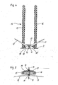
- the Fig. 1 shows a mast 1 and a flat foundation 2 for an offshore wind turbine in a first stage.
- the installation of the wind energy plant takes place on a company premises 3 near or directly at a harbor basin.
- the mast 1 comprises a base element 4 with the flat foundation 2 and at least one middle mast element 5.
- Attached to the mast element 5 is a platform 7 with a ladder 8 leading to it. wherein the height of the platform 7 is dimensioned on the flat foundation 2 so that when installing the wind turbine in the sea, the platform 7 is always above sea level.
- Fig. 2 is the arrangement according to Fig. 1 shown in a second stage with an upper mast piece 9, which is placed on the mast element 6 and firmly connected thereto.
- the placement of the mast sections of the base member 4 on the flat foundation 2 and then successively placing each of the mast element 6 and the upper mast piece 9 can be done by means of a suitable crane. It can also be provided a different order of assembly of the individual elements forming the mast, which takes place for example by means of a gantry crane, which will be described in more detail later.
- the Fig. 3 shows a laying on the premises 3 machine nacelle 10 of the wind turbine, wherein the nacelle 10 includes a rotor 11 which is equipped with two rotor blades 12, 13.
- the nacelle 10 includes a rotor 11 which is equipped with two rotor blades 12, 13.
- assembly can be found on the in Fig. 2 mast 1 mounted and then provided with a third rotor blade.
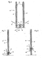
- the Fig. 4 shows the front view of a gantry crane 14, which consists essentially of two crane masts 15, 16 and arranged between them Traverse 17.
- the crossbar 17 is vertically displaceable over the entire height of the crane masts 15, 16, wherein in Fig. 4 the lowest position is shown. In this position, the nacelle 10 can be picked up by the traverse 17, with the rotor 11 with the rotor blades 12, 13 in front of the gantry crane 14.
- a working platform 18 which consists of two stage elements 18 ', which are still folded when feeding the nacelle 10 and attaching them to the crossbar 17 to the side and thus occupy a "non-insert position".
- Fig. 5 is a plan view of the gantry crane 14 with supplied nacelle 10 including rotor 11 and rotor blades 12, 13 shown.
- the nacelle 10 is pushed in the direction of the arrows 19 under the traverse 17 until the in Fig. 5 shown position is reached. In this case, a sufficient distance of the rotor blades 12, 13 given to the crane masts 15, 16.
- the Fig. 6 shows the gantry crane 14 with the crane masts 15, 16 a bit far up traversed Traverse 17, so that the machine nacelle 10 are lifted off the ground with rotor 11 and the stage elements 18 'of the platform 18 are folded into a "use position", below At the working platform a receiving device for a rotor blade 20 for transporting this third rotor blade 20 may be provided.
- stage parts of a mounting platform 24 are provided, which in Fig. 6 are shown folded and whose function will be described later.
- Fig. 7 is a side view of the gantry crane 14 with the position of the crossbar 17 and nacelle 10 shown these in Fig. 6 taking.
- the reference numerals with those of 4 to 6 match. From the third rotor blade 20, only the recorded on the platform 18 section is shown.
- the Fig. 8 shows a representation according to Fig. 7 with raised cross member 17 and machine nacelle 10 with rotor 11.
- Fig. 8 By lifting the end of the rotor blade 20 with the raising of the crossbar 17 is in Fig. 8 shown oblique position of the rotor blade 20 is reached.
- the same reference numerals of the same components are here Fig. 4 to 7 used.
- FIG. 9 Traverse 17 is raised to the crane masts 15, 16 of the gantry crane 14 so far that the third rotor blade 20 occupies a position in which a mounting on the rotor 11 can take place.
- a front part 21 of the rotor blade 20 is guided by means of a device until the rotor blade 20 is mounted on the rotor 11.
- a side view of the arrangement according to Fig. 9 is in Fig. 10 illustrated, wherein the reference numerals for like components also agree with those of the preceding figures.
- Fig. 11 can be seen after the mounting of the rotor blade 20 on the rotor 11, the rotor blade 20 on the rotor, so that a guide of the rotor blade is no longer necessary and the device is removed.
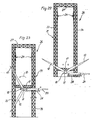
- Fig. 12 shows, the cross member 17 with machine nacelle 10 and fully equipped rotor 11 is driven close to the upper end of the crane masts 15, 16 of the gantry crane 14, leaving a small residual path for a possible compensation remains.
- the Fig. 13 shows a representation of the gantry crane 14 as in Fig. 12 , but with mast 1 with flat foundation 2 positioned between the crane masts 15, 16. Because of the rotor blade 20 pointing downwards, the mast 1 with the flat foundation is brought from the rear side into the position between the crane masts 15, 16, at which the fastening device for mounting the machine nacelle 10 on the mast 1 vertically located exactly above the upper mast piece 9, but in an in Fig. 13 shown distance.
- Fig. 14 is the top view of the arrangement according to Fig. 13 shown.
- the arrow 23 indicates the direction in which the mast 1 and the flat foundation 2 are introduced into the intermediate space between the crane masts 15, 16.
- the same reference numerals correspond to the same figures for the same components.
- the Fig. 15 shows the gantry crane 14 with mast 1 positioned between the crane masts 15, 16 and flat foundation 2 for the offshore wind energy plant.
- the two stage parts of an assembly platform 24 situated in the upper area of the crane masts 15, 16 are folded out toward the center and fix the upper mast piece 9 against which the assembly platform 24 rests. This fixation serves to ensure that the mast 1 does not make any relative movement to the gantry crane 14 when the nacelle 10 is placed on it.
- the machine nacelle 10 can then be placed on the upper mast piece 9, for which purpose first the working platform 18 is folded and then the traverse 17 is lowered with the machine nacelle 10 and rotor 11.
- FIGS. 15 and 16 show, wherein the stage elements 18 'of the platform 18 are folded back under the cross member 17 and the machine nacelle 10 is seated on the upper pole piece 9. Now, the assembly work for fixing the nacelle 10 on the mast piece 9 can be performed.
- the reference numerals in FIGS. 15 and 16 match for the same parts with those of the previously described figures.
- a mast 1, 2 flat foundation, machine nacelle 10 and rotor 11 existing wind turbine 25 is completed, which is completely transported and permanently installed in an offshore area.
- the transport takes place by means of a floating transport device, which can be lowered at the destination for the wind turbine 25 and the wind turbine settles on the seabed.
- Fig. 19 moved out of the gantry crane 14, in the direction of the arrow 26, which is also preferably the direction in which the transport device for transferring the wind turbine 25 is located at the destination in the harbor basin.
- the gantry crane 14 for the installation of the wind turbine 25 is a fixed installed on the premises Gantry crane.
- the mast 1 can be constructed by means of the gantry crane 14. For this purpose, for example, first the upper mast piece 9 is received by the cross member 17 and raised until the mast member 6 fits upright below. It then takes the connection of mast element 6 and mast piece 9.
- the mast 1 it is also possible, depending on the construction of the mast 1, to provide several mast elements or mast pieces. After further raising the crossmember 17 with it located subunit of the mast to a height that allows a vertical arrangement of the base member 4 below, the base member 4 is supplied and placed thereon and attached the subunit, so that the mast 1 is complete. If the base element 4 is initially not provided with the flat foundation 2, after further lifting of the traverse 17, the flat foundation 2 is brought between the crane masts 15, 16 and the mast 1 is fastened to the flat foundation 2. In addition to this example of the method for mounting the mast 1, other processes are possible.
- Fig. 20 the mast 1 with flat foundation 2 and base element 4 is shown, as he is the one in Fig. 1 corresponds to the platform 7, which stands on the premises 3 for installation of wind turbines.
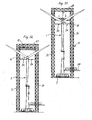
- the Fig. 21 shows a front frame 31 of a gantry crane 26, said frame 31 consists of two crane masts 33, 34 and a stationary bridge 27 at the upper end of the crane masts 33, 34.
- the gantry crane 26 includes - as later will be explained in more detail - a total of four crane masts.
- the vertically displaceable cross member 17 is arranged between the crane masts 33, 34.
- the cross member 17 in the lowest position in which the inclusion of the machine nacelle 10 at the bottom of the cross member 17 is possible.
- a rotor blade 12 is already mounted, another rotor blade 13 is on the mounting plate 28 for attachment to the rotor 11 ready.
- the mounting platform 24 is provided in the upper area.
- Fig. 22 the front frame 31 of the gantry crane 26 is shown, wherein the rotor blade 13 is mounted on the rotor 11 in addition to the rotor blade 12 and on the mounting plate 28, the third rotor blade 20 is ready.
- the cross member 17 is vertically upwards in the in Fig. 23 shown position and also the mounting plate 28, so that the rotor 11 can be rotated in the direction of arrow 30 to allow the attachment of the rotor blade 20 to the rotor 11.
- the mounting plate 28 can be lowered again, as is made Fig. 24 is apparent.
- Fig. 25 Traverse 17 is then raised with the nacelle 10 vertically up to the bridge 27. All other reference numerals in FIGS. 22 to 25 agree with those of the same parts Fig. 21 match.
- a side view of the gantry crane 26 is shown, however, with traverse 17 and nacelle 10 on the front frame 31 at mid-height.
- a vertically displaceable device 35th arranged, which serves for receiving and for lifting mast elements 36, which are placed on the mast 1 and the mast element 5 located thereon.
- the apparatus 35 is shown in two different heights on the rear frame 32.
- the device 35 comprises a lifting crossmember 37 located between the crane masts of the rear frame and a crane crane arm 38 with crane hooks arranged underneath.
- the mast elements 36 are attached to the crane hook, then conveyed by driving up the Hubtraverse 37 upwards and finally pivoted by pivoting the turntable 38 or extending a telescopic arm on the previously mounted mast element and placed on this.
- the Fig. 27 shows a section through the gantry crane 26 along the line XXVII-XXVII with supplied flat foundation 2 or mast 1.
- the gantry crane 26 consists of the front frame 31 and the rear frame 32, the latter also two crane masts 33, 34 and a stationary bridge 27th includes. For a total of 4 crane masts 33, 34 are available.
- the front frame 31 and the rear frame 32 are connected to each other by means of the webs 29 '.
- the cross member 17 is arranged with the machine nacelle 10 located thereon.
- Fig. 28 is shown a front view of the gantry crane 26, wherein the flat foundation 2 with mast 1 within the front frame 31 between the crane masts 33, 34 is located.
- Fig. 29 becomes clear that a view of the section along the line XXIX-XXIX in Fig. 28 shows, the position for mounting the nacelle 10 is on the mast 1 located on the flat foundation 2, the mast being placed under the fixed bridge 27 of the front frame 31 for this purpose.
- the reference numerals in Fig. 28 and 29 for equal parts with those of Fig. 20 to 27 match.
- Fig. 30 is a view of the gantry crane 26 with between the crane masts 33, 34 of the front frame 31 positioned mast 1 and 2 flat foundation for the offshore wind turbine shown.
- the two stage parts of the mounting platform 24 located in the upper area on the crane masts 33, 34 are folded out towards the center and fix the upper end of the mast 1, on which the assembly platform 24 rests. Relative movements of the mast 1 to the gantry crane 26 during assembly of the nacelle 10 on the mast 1 are thus avoided.
- Fig. 31 shows - the cross member 17 lowered with the nacelle 10 and the latter placed on the mast end.
- the assembly work for fixing the nacelle 10 on the mast 1 can be performed.
- the nacelle 10 is released from the cross member 17 and this according to Fig. 32 moved up to the bridge 27.
- the folding of the stage parts of the assembly platform 24 takes place as in Fig. 33 shown.
- the mast 1, 2 flat foundation, machine nacelle 10 and rotor 11 existing wind turbine 25 is completed, which is completely transported and permanently installed in an offshore area.
- this is according to Fig. 34 moved forward from the gantry crane 26 in the direction of arrow 39. From this plan view it can be seen that the side traverses 29 at the upper end between the front frame 31 and the rear frame 32 are made wider than the underlying side trusses 29 '(see. Fig. 29 ).
- FIGS. 21 to 36 gantry crane 26 described not only offers the advantage of better mechanical strength and stability, but also allows the simultaneous assembly of the rotor blades 12, 13, 20 on the rotor 11 and the construction of the mast by mounting the mast elements 36 on the lower mast element 5 on the flat foundation. 2 ,
Claims (10)
- Dispositif pour fabriquer à terre des installations aérogénératrices en mer (25), avec une grue pour soulever et poser des composants, des modules et/ou une nacelle (10) de l'installation aérogénératrice, étant précisé que la grue est conçue comme une grue à portique (14) qui comprend au moins deux poteaux de grue (15, 16) et au moins une traverse (17) montée mobile verticalement sur les poteaux de grue (15, 16), et qu'il est prévu sur la traverse (17) un dispositif pour recevoir les composants, les modules et/ou la nacelle (10), étant précisé que sur le côté inférieur de la traverse (17) est disposée une plate-forme de travail (18) et que sur le dessous de la plate-forme de travail (18) est prévu un dispositif de réception pour une pale de rotor (20), caractérisé en ce que la plate-forme de travail (18) comprend deux éléments de plate-forme (18'), montés pivotants sur le côté inférieur de la traverse (17), qui peuvent adopter une position d'utilisation prévue pour l'exécution de travaux, ainsi qu'une position hors utilisation.
- Dispositif selon la revendication 1,
caractérisé en ce que sur l'un au moins des poteaux de grue (15, 16 ; 33, 34) est disposée, dans la zone supérieure, une plate-forme de montage (24) qui peut adopter une position d'utilisation et une position hors utilisation. - Dispositif selon la revendication 2,
caractérisé en ce que la plate-forme de montage (24) comprend deux éléments de plate-forme montés pivotants qui sont prévus sur les côtés tournés vers l'autre des poteaux de grue (15, 16 ; 33, 34), étant précisé que les éléments de plate-forme sont conçus, sur les côtés tournés l'un vers l'autre, de manière à entourer dans la position d'utilisation le mât (1) ou une pièce de mât (9). - Dispositif selon l'une des revendications 1 à 3,
caractérisé en ce que la grue à portique (26) comprend un châssis avant et un châssis arrière (31, 34), étant précisé que chaque châssis (31, 32) se compose de deux poteaux de grue (33, 34) et d'un pont fixe (27) qui relie les extrémités supérieures des poteaux de grue (33, 34). - Dispositif selon la revendication 4,
caractérisé en ce que le châssis avant (31) est relié au châssis arrière (32) à l'aide de traverses latérales (29, 29') fixées, en haut, aux poteaux de grue (33, 34). - Dispositif selon l'une des revendications 4 ou 5,
caractérisé en ce qu'il est prévu sur le châssis arrière (32) un dispositif (35) pour recevoir et pour soulever des éléments de mât (36), étant précisé que le dispositif (35) comprend une traverse de levage (37) et un bras de grue pivotante (38). - Procédé pour fabriquer à terre des installations aérogénératrices en mer (25), étant précisé qu'une nacelle (10) est soulevée à l'aide d'une grue et est montée sur un mât (1) de l'installation aérogénératrice (25), qu'un dispositif de réception prévu sur une traverse (17) mobile verticalement d'un grue à portique (14, 26) est tout d'abord relié à une nacelle (10) et que ladite nacelle (10) est ensuite soulevée, étant précisé que la traverse (17) est déplacée verticalement vers le bas sur les poteaux de grue (15, 16 ; 33, 36) et que dans une position abaissée, la nacelle (10) est fixée au côté inférieur de la traverse (17) et que le soulèvement de la nacelle (10) se fait plus tard grâce au soulèvement de la traverse (17),
caractérisé en ce que deux éléments de plate-forme (18') qui sont montés pivotants sur le côté inférieur de la traverse (17) et qui forment une plate-forme de travail (18) pivotent jusqu'à une position d'utilisation et le soulèvement de la traverse (17) se fait en plusieurs étapes, étant précisé qu'après une première étape de soulèvement, la plate-forme (18) est amenée dans une position d'utilisation, et qu'une fois qu'une hauteur prédéfinie de la nacelle (10) est atteinte, un mât (1) de l'installation aérogénératrice (25) est amené entre les poteaux (15, 16 ; 33, 36) de la grue à portique (14, 26) et est positionné sous la nacelle (10) de telle sorte que grâce à l'abaissement de la nacelle (10), celle-ci est déposée sur l'extrémité supérieure du mât (1) et est reliée solidement à celui-ci, et qu'une fois que l'installation aérogénératrice en mer (25) est terminée, elle est sortie de la grue à portique (14, 26). - Procédé selon la revendication 7,
caractérisé en ce qu'après le positionnement du mât (1) entre les poteaux (15, 16 ; 33, 34) de la grue à portique (14), des éléments d'une plate-forme de montage (24) disposée dans la zone supérieure des poteaux de grue (15, 16 ; 33, 34) pivotent en direction du mât (1) de manière à entourer et à enserrer entre eux une pièce de mât supérieure. - Procédé selon l'une des revendications 7 ou 8,
caractérisé en ce que le rotor (11) qui se trouve sur la nacelle (10) est équipé, avant le soulèvement de la traverse (17), de deux pales de rotor (12, 13), et après un soulèvement de la traverse (17) jusqu'à une hauteur définie, une troisième pale (20) est montée sur le rotor (11). - Procédé selon la revendication 7,
caractérisé en ce que le mât (1) est érigé à l'aide de la grue à portique (26) grâce au fait qu'un fondement plat (2) avec un premier élément de mât (5) est positionné dans la zone d'un châssis arrière (32) de la grue à portique (26), et qu'à l'aide d'un dispositif (35) plusieurs éléments de mât (36) sont successivement soulevés et montés les uns sur les autres.
Applications Claiming Priority (2)
| Application Number | Priority Date | Filing Date | Title |
|---|---|---|---|
| DE102009008870A DE102009008870A1 (de) | 2009-02-13 | 2009-02-13 | Vorrichtung und Verfahren zur Herstellung von Offshore-Windenergieanlagen |
| PCT/EP2010/000754 WO2010091829A2 (fr) | 2009-02-13 | 2010-02-06 | Équipement et procédé pour la fabrication d'installations aérogénératrices en mer |
Publications (2)
| Publication Number | Publication Date |
|---|---|
| EP2396537A2 EP2396537A2 (fr) | 2011-12-21 |
| EP2396537B1 true EP2396537B1 (fr) | 2015-07-29 |
Family
ID=42557658
Family Applications (1)
| Application Number | Title | Priority Date | Filing Date |
|---|---|---|---|
| EP10729779.8A Not-in-force EP2396537B1 (fr) | 2009-02-13 | 2010-02-06 | Équipement et procédé pour la fabrication d'installations aérogénératrices en mer |
Country Status (3)
| Country | Link |
|---|---|
| EP (1) | EP2396537B1 (fr) |
| DE (1) | DE102009008870A1 (fr) |
| WO (1) | WO2010091829A2 (fr) |
Families Citing this family (4)
| Publication number | Priority date | Publication date | Assignee | Title |
|---|---|---|---|---|
| CN103557126B (zh) * | 2013-10-23 | 2016-05-04 | 中国中铁航空港建设集团有限公司 | 风力发电设备的安装装置及安装方法 |
| CN103850891B (zh) * | 2014-02-27 | 2016-08-17 | 北京金风科创风电设备有限公司 | 风机塔架的构件的对接装置及方法、平移机构及静止机构 |
| GB201819191D0 (en) | 2018-11-26 | 2019-01-09 | W3G Marine Ltd | Method of turbine assembly |
| WO2023194711A1 (fr) * | 2022-04-04 | 2023-10-12 | Planet 42 Limited | Améliorations apportées et se rapportant à l'assemblage d'une structure |
Citations (3)
| Publication number | Priority date | Publication date | Assignee | Title |
|---|---|---|---|---|
| CN2229443Y (zh) * | 1995-08-15 | 1996-06-19 | 刘跃美 | 一种组合式多功能塔式起重机 |
| DE60009007T2 (de) * | 1999-11-17 | 2005-03-10 | Bonus Energy A/S | Methode und schiff zur installation von windkraftanlagen auf see |
| WO2008084971A1 (fr) * | 2007-01-11 | 2008-07-17 | Dong Taek Suh | Procédé d'installation d'un générateur d'énergie éolienne en mer au moyen d'un rail de guidage |
Family Cites Families (6)
| Publication number | Priority date | Publication date | Assignee | Title |
|---|---|---|---|---|
| GB1092403A (en) * | 1965-08-17 | 1967-11-22 | Anderston Clyde Engineers Ltd | Self erecting bridge crane |
| US4546852A (en) * | 1984-02-07 | 1985-10-15 | Fruehauf Corporation | Adjustable service platform apparatus for a gantry crane |
| ATE305895T1 (de) * | 1999-06-03 | 2005-10-15 | D H Blattner & Sons Inc | An führungsschienen kletterende hebeplattform und verfahren |
| WO2005028781A2 (fr) * | 2003-09-16 | 2005-03-31 | Clement Hiel | Pylone composite d'eolienne et son procede d'assemblage |
| DE102005006988A1 (de) | 2005-02-15 | 2006-08-17 | Ed. Züblin Ag | Flächengründung, bevorzugt aufgelöst, für Offshore-Windenergieanlage |
| NL1032591C2 (nl) * | 2006-09-28 | 2008-03-31 | Mecal Applied Mechanics B V | Hijskraan en werkwijze. |
-
2009
- 2009-02-13 DE DE102009008870A patent/DE102009008870A1/de not_active Ceased
-
2010
- 2010-02-06 EP EP10729779.8A patent/EP2396537B1/fr not_active Not-in-force
- 2010-02-06 WO PCT/EP2010/000754 patent/WO2010091829A2/fr active Application Filing
Patent Citations (3)
| Publication number | Priority date | Publication date | Assignee | Title |
|---|---|---|---|---|
| CN2229443Y (zh) * | 1995-08-15 | 1996-06-19 | 刘跃美 | 一种组合式多功能塔式起重机 |
| DE60009007T2 (de) * | 1999-11-17 | 2005-03-10 | Bonus Energy A/S | Methode und schiff zur installation von windkraftanlagen auf see |
| WO2008084971A1 (fr) * | 2007-01-11 | 2008-07-17 | Dong Taek Suh | Procédé d'installation d'un générateur d'énergie éolienne en mer au moyen d'un rail de guidage |
Also Published As
| Publication number | Publication date |
|---|---|
| DE102009008870A1 (de) | 2010-09-16 |
| WO2010091829A3 (fr) | 2010-11-25 |
| WO2010091829A2 (fr) | 2010-08-19 |
| EP2396537A2 (fr) | 2011-12-21 |
Similar Documents
| Publication | Publication Date | Title |
|---|---|---|
| DE60126984T2 (de) | Verfahren und vorrichtung zur anordnung mindestens einer windturbine an offenem wasser | |
| DE102013011489B4 (de) | Turmdrehkran | |
| EP3252304B1 (fr) | Système de prémontage horizontal d'un rotor d'éolienne | |
| DE60316279T2 (de) | Verfahren und wasserfahrzeug zur manipulation einer offshore-anlage | |
| DE202009006507U1 (de) | Führungsgestell zum vertikalen Führen von mindestens einem Fundamentpfahl beim Errichten eines Fundaments einer Offshore-Windenergieanlage und Stapel-, Aufricht- und Absenkvorrichtung zum Errichten eines Fundaments einer Offshore-Windenergieanlage | |
| EP2539219B1 (fr) | Dispositif pour le transport et l'installation d'un agencement d'une éolienne offshore comprenant une embase et procédé pour le transport et l'installation d'un tel agencement muni d'une embase | |
| EP2396537B1 (fr) | Équipement et procédé pour la fabrication d'installations aérogénératrices en mer | |
| WO2005097661A1 (fr) | Grue a contrepoids stationnaire | |
| EP3191662B1 (fr) | Procédé de montage d'une pluralité d'éléments de précontrainte dans une tour au moyen d'une grue et dispositif de déroulage destiné à être utilisé dans ledit procédé | |
| EP1321670B1 (fr) | Système de transport et d'installation d'éoliennes marines | |
| EP2383219B1 (fr) | Procédé de préparation d'un dispositif de levage sur une plate-forme | |
| DE102010015412A1 (de) | Verfahren zum Transport und zur Montage einer Windkraftanlage und Transport- und Montagesystem | |
| EP1321671B1 (fr) | Barge de transport pour éoliennes marines | |
| DE102016116166A1 (de) | Pfahlgründung | |
| DE10028513A1 (de) | Verfahren und Vorrichtung zur Montage einer Windkraftanlage | |
| EP3530814B1 (fr) | Procédé de mise en place d'un poste électrique et kit de fondation pour un poste électrique | |
| DE112006001727T5 (de) | Montage von Offshore-Anlagen | |
| EP3581794B1 (fr) | Système de montage et procédé de montage d'un rotor en étoile pour une éolienne | |
| EP1634998A1 (fr) | Transport et fondation d'unités fonctionelles, en particulier d'éoliennes marines. | |
| EP1321669B1 (fr) | Système de transport et d'installation d'éoliennes marines | |
| EP2321214B1 (fr) | Procédé pour produire au moins un module d'éolienne offshore | |
| WO2019170831A1 (fr) | Ascenseur de bateau | |
| DE10233227A1 (de) | Transporteinrichtung | |
| WO2001094249A1 (fr) | Procede et dispositif de montage d'une eolienne | |
| DE202004021468U1 (de) | Vorrichtung zum Transport und Errichtung einer Windkraftanlage |
Legal Events
| Date | Code | Title | Description |
|---|---|---|---|
| PUAI | Public reference made under article 153(3) epc to a published international application that has entered the european phase |
Free format text: ORIGINAL CODE: 0009012 |
|
| 17P | Request for examination filed |
Effective date: 20110809 |
|
| AK | Designated contracting states |
Kind code of ref document: A2 Designated state(s): AT BE BG CH CY CZ DE DK EE ES FI FR GB GR HR HU IE IS IT LI LT LU LV MC MK MT NL NO PL PT RO SE SI SK SM TR |
|
| RAP1 | Party data changed (applicant data changed or rights of an application transferred) |
Owner name: STRABAG OFFSHORE WIND GMBH |
|
| DAX | Request for extension of the european patent (deleted) | ||
| 17Q | First examination report despatched |
Effective date: 20120801 |
|
| RAP1 | Party data changed (applicant data changed or rights of an application transferred) |
Owner name: STRABAG OFFSHORE WIND GMBH |
|
| REG | Reference to a national code |
Ref country code: DE Ref legal event code: R079 Ref document number: 502010009958 Country of ref document: DE Free format text: PREVIOUS MAIN CLASS: F03D0001000000 Ipc: B66C0019020000 |
|
| GRAP | Despatch of communication of intention to grant a patent |
Free format text: ORIGINAL CODE: EPIDOSNIGR1 |
|
| RIC1 | Information provided on ipc code assigned before grant |
Ipc: F03D 1/00 20060101ALI20150219BHEP Ipc: B66C 19/02 20060101AFI20150219BHEP Ipc: B66C 23/18 20060101ALI20150219BHEP |
|
| INTG | Intention to grant announced |
Effective date: 20150312 |
|
| GRAS | Grant fee paid |
Free format text: ORIGINAL CODE: EPIDOSNIGR3 |
|
| GRAA | (expected) grant |
Free format text: ORIGINAL CODE: 0009210 |
|
| AK | Designated contracting states |
Kind code of ref document: B1 Designated state(s): AT BE BG CH CY CZ DE DK EE ES FI FR GB GR HR HU IE IS IT LI LT LU LV MC MK MT NL NO PL PT RO SE SI SK SM TR |
|
| REG | Reference to a national code |
Ref country code: GB Ref legal event code: FG4D Free format text: NOT ENGLISH |
|
| REG | Reference to a national code |
Ref country code: CH Ref legal event code: EP |
|
| REG | Reference to a national code |
Ref country code: AT Ref legal event code: REF Ref document number: 739106 Country of ref document: AT Kind code of ref document: T Effective date: 20150815 |
|
| REG | Reference to a national code |
Ref country code: IE Ref legal event code: FG4D Free format text: LANGUAGE OF EP DOCUMENT: GERMAN |
|
| REG | Reference to a national code |
Ref country code: DE Ref legal event code: R096 Ref document number: 502010009958 Country of ref document: DE |
|
| REG | Reference to a national code |
Ref country code: LT Ref legal event code: MG4D |
|
| REG | Reference to a national code |
Ref country code: NL Ref legal event code: MP Effective date: 20150729 |
|
| PG25 | Lapsed in a contracting state [announced via postgrant information from national office to epo] |
Ref country code: NO Free format text: LAPSE BECAUSE OF FAILURE TO SUBMIT A TRANSLATION OF THE DESCRIPTION OR TO PAY THE FEE WITHIN THE PRESCRIBED TIME-LIMIT Effective date: 20151029 Ref country code: LV Free format text: LAPSE BECAUSE OF FAILURE TO SUBMIT A TRANSLATION OF THE DESCRIPTION OR TO PAY THE FEE WITHIN THE PRESCRIBED TIME-LIMIT Effective date: 20150729 Ref country code: FI Free format text: LAPSE BECAUSE OF FAILURE TO SUBMIT A TRANSLATION OF THE DESCRIPTION OR TO PAY THE FEE WITHIN THE PRESCRIBED TIME-LIMIT Effective date: 20150729 Ref country code: LT Free format text: LAPSE BECAUSE OF FAILURE TO SUBMIT A TRANSLATION OF THE DESCRIPTION OR TO PAY THE FEE WITHIN THE PRESCRIBED TIME-LIMIT Effective date: 20150729 Ref country code: GR Free format text: LAPSE BECAUSE OF FAILURE TO SUBMIT A TRANSLATION OF THE DESCRIPTION OR TO PAY THE FEE WITHIN THE PRESCRIBED TIME-LIMIT Effective date: 20151030 |
|
| PG25 | Lapsed in a contracting state [announced via postgrant information from national office to epo] |
Ref country code: SE Free format text: LAPSE BECAUSE OF FAILURE TO SUBMIT A TRANSLATION OF THE DESCRIPTION OR TO PAY THE FEE WITHIN THE PRESCRIBED TIME-LIMIT Effective date: 20150729 Ref country code: PL Free format text: LAPSE BECAUSE OF FAILURE TO SUBMIT A TRANSLATION OF THE DESCRIPTION OR TO PAY THE FEE WITHIN THE PRESCRIBED TIME-LIMIT Effective date: 20150729 Ref country code: ES Free format text: LAPSE BECAUSE OF FAILURE TO SUBMIT A TRANSLATION OF THE DESCRIPTION OR TO PAY THE FEE WITHIN THE PRESCRIBED TIME-LIMIT Effective date: 20150729 Ref country code: PT Free format text: LAPSE BECAUSE OF FAILURE TO SUBMIT A TRANSLATION OF THE DESCRIPTION OR TO PAY THE FEE WITHIN THE PRESCRIBED TIME-LIMIT Effective date: 20151130 Ref country code: HR Free format text: LAPSE BECAUSE OF FAILURE TO SUBMIT A TRANSLATION OF THE DESCRIPTION OR TO PAY THE FEE WITHIN THE PRESCRIBED TIME-LIMIT Effective date: 20150729 Ref country code: IS Free format text: LAPSE BECAUSE OF FAILURE TO SUBMIT A TRANSLATION OF THE DESCRIPTION OR TO PAY THE FEE WITHIN THE PRESCRIBED TIME-LIMIT Effective date: 20151129 |
|
| PG25 | Lapsed in a contracting state [announced via postgrant information from national office to epo] |
Ref country code: NL Free format text: LAPSE BECAUSE OF FAILURE TO SUBMIT A TRANSLATION OF THE DESCRIPTION OR TO PAY THE FEE WITHIN THE PRESCRIBED TIME-LIMIT Effective date: 20150729 |
|
| PG25 | Lapsed in a contracting state [announced via postgrant information from national office to epo] |
Ref country code: EE Free format text: LAPSE BECAUSE OF FAILURE TO SUBMIT A TRANSLATION OF THE DESCRIPTION OR TO PAY THE FEE WITHIN THE PRESCRIBED TIME-LIMIT Effective date: 20150729 Ref country code: DK Free format text: LAPSE BECAUSE OF FAILURE TO SUBMIT A TRANSLATION OF THE DESCRIPTION OR TO PAY THE FEE WITHIN THE PRESCRIBED TIME-LIMIT Effective date: 20150729 Ref country code: CZ Free format text: LAPSE BECAUSE OF FAILURE TO SUBMIT A TRANSLATION OF THE DESCRIPTION OR TO PAY THE FEE WITHIN THE PRESCRIBED TIME-LIMIT Effective date: 20150729 Ref country code: SK Free format text: LAPSE BECAUSE OF FAILURE TO SUBMIT A TRANSLATION OF THE DESCRIPTION OR TO PAY THE FEE WITHIN THE PRESCRIBED TIME-LIMIT Effective date: 20150729 Ref country code: IT Free format text: LAPSE BECAUSE OF FAILURE TO SUBMIT A TRANSLATION OF THE DESCRIPTION OR TO PAY THE FEE WITHIN THE PRESCRIBED TIME-LIMIT Effective date: 20150729 |
|
| REG | Reference to a national code |
Ref country code: DE Ref legal event code: R097 Ref document number: 502010009958 Country of ref document: DE |
|
| PG25 | Lapsed in a contracting state [announced via postgrant information from national office to epo] |
Ref country code: BE Free format text: LAPSE BECAUSE OF NON-PAYMENT OF DUE FEES Effective date: 20160229 Ref country code: RO Free format text: LAPSE BECAUSE OF FAILURE TO SUBMIT A TRANSLATION OF THE DESCRIPTION OR TO PAY THE FEE WITHIN THE PRESCRIBED TIME-LIMIT Effective date: 20150729 |
|
| PLBE | No opposition filed within time limit |
Free format text: ORIGINAL CODE: 0009261 |
|
| STAA | Information on the status of an ep patent application or granted ep patent |
Free format text: STATUS: NO OPPOSITION FILED WITHIN TIME LIMIT |
|
| 26N | No opposition filed |
Effective date: 20160502 |
|
| PG25 | Lapsed in a contracting state [announced via postgrant information from national office to epo] |
Ref country code: SI Free format text: LAPSE BECAUSE OF FAILURE TO SUBMIT A TRANSLATION OF THE DESCRIPTION OR TO PAY THE FEE WITHIN THE PRESCRIBED TIME-LIMIT Effective date: 20150729 |
|
| PG25 | Lapsed in a contracting state [announced via postgrant information from national office to epo] |
Ref country code: LU Free format text: LAPSE BECAUSE OF FAILURE TO SUBMIT A TRANSLATION OF THE DESCRIPTION OR TO PAY THE FEE WITHIN THE PRESCRIBED TIME-LIMIT Effective date: 20160206 Ref country code: MC Free format text: LAPSE BECAUSE OF FAILURE TO SUBMIT A TRANSLATION OF THE DESCRIPTION OR TO PAY THE FEE WITHIN THE PRESCRIBED TIME-LIMIT Effective date: 20150729 |
|
| REG | Reference to a national code |
Ref country code: CH Ref legal event code: PL |
|
| PG25 | Lapsed in a contracting state [announced via postgrant information from national office to epo] |
Ref country code: CH Free format text: LAPSE BECAUSE OF NON-PAYMENT OF DUE FEES Effective date: 20160229 Ref country code: LI Free format text: LAPSE BECAUSE OF NON-PAYMENT OF DUE FEES Effective date: 20160229 |
|
| REG | Reference to a national code |
Ref country code: FR Ref legal event code: ST Effective date: 20161028 |
|
| REG | Reference to a national code |
Ref country code: IE Ref legal event code: MM4A |
|
| PG25 | Lapsed in a contracting state [announced via postgrant information from national office to epo] |
Ref country code: FR Free format text: LAPSE BECAUSE OF NON-PAYMENT OF DUE FEES Effective date: 20160229 Ref country code: IE Free format text: LAPSE BECAUSE OF NON-PAYMENT OF DUE FEES Effective date: 20160206 |
|
| REG | Reference to a national code |
Ref country code: AT Ref legal event code: MM01 Ref document number: 739106 Country of ref document: AT Kind code of ref document: T Effective date: 20160206 |
|
| PGFP | Annual fee paid to national office [announced via postgrant information from national office to epo] |
Ref country code: DE Payment date: 20170222 Year of fee payment: 8 |
|
| PG25 | Lapsed in a contracting state [announced via postgrant information from national office to epo] |
Ref country code: AT Free format text: LAPSE BECAUSE OF NON-PAYMENT OF DUE FEES Effective date: 20160206 |
|
| PGFP | Annual fee paid to national office [announced via postgrant information from national office to epo] |
Ref country code: GB Payment date: 20170221 Year of fee payment: 8 |
|
| PG25 | Lapsed in a contracting state [announced via postgrant information from national office to epo] |
Ref country code: MT Free format text: LAPSE BECAUSE OF FAILURE TO SUBMIT A TRANSLATION OF THE DESCRIPTION OR TO PAY THE FEE WITHIN THE PRESCRIBED TIME-LIMIT Effective date: 20150729 |
|
| PG25 | Lapsed in a contracting state [announced via postgrant information from national office to epo] |
Ref country code: CY Free format text: LAPSE BECAUSE OF FAILURE TO SUBMIT A TRANSLATION OF THE DESCRIPTION OR TO PAY THE FEE WITHIN THE PRESCRIBED TIME-LIMIT Effective date: 20150729 Ref country code: SM Free format text: LAPSE BECAUSE OF FAILURE TO SUBMIT A TRANSLATION OF THE DESCRIPTION OR TO PAY THE FEE WITHIN THE PRESCRIBED TIME-LIMIT Effective date: 20150729 Ref country code: HU Free format text: LAPSE BECAUSE OF FAILURE TO SUBMIT A TRANSLATION OF THE DESCRIPTION OR TO PAY THE FEE WITHIN THE PRESCRIBED TIME-LIMIT; INVALID AB INITIO Effective date: 20100206 |
|
| PG25 | Lapsed in a contracting state [announced via postgrant information from national office to epo] |
Ref country code: TR Free format text: LAPSE BECAUSE OF FAILURE TO SUBMIT A TRANSLATION OF THE DESCRIPTION OR TO PAY THE FEE WITHIN THE PRESCRIBED TIME-LIMIT Effective date: 20150729 Ref country code: MK Free format text: LAPSE BECAUSE OF FAILURE TO SUBMIT A TRANSLATION OF THE DESCRIPTION OR TO PAY THE FEE WITHIN THE PRESCRIBED TIME-LIMIT Effective date: 20150729 |
|
| PG25 | Lapsed in a contracting state [announced via postgrant information from national office to epo] |
Ref country code: BG Free format text: LAPSE BECAUSE OF FAILURE TO SUBMIT A TRANSLATION OF THE DESCRIPTION OR TO PAY THE FEE WITHIN THE PRESCRIBED TIME-LIMIT Effective date: 20150729 |
|
| REG | Reference to a national code |
Ref country code: DE Ref legal event code: R119 Ref document number: 502010009958 Country of ref document: DE |
|
| GBPC | Gb: european patent ceased through non-payment of renewal fee |
Effective date: 20180206 |
|
| PG25 | Lapsed in a contracting state [announced via postgrant information from national office to epo] |
Ref country code: DE Free format text: LAPSE BECAUSE OF NON-PAYMENT OF DUE FEES Effective date: 20180901 |
|
| PG25 | Lapsed in a contracting state [announced via postgrant information from national office to epo] |
Ref country code: GB Free format text: LAPSE BECAUSE OF NON-PAYMENT OF DUE FEES Effective date: 20180206 |