EP2395946B1 - Keramischer pfanneneinsatz mit invers-konischem führungszapfen - Google Patents
Keramischer pfanneneinsatz mit invers-konischem führungszapfen Download PDFInfo
- Publication number
- EP2395946B1 EP2395946B1 EP10702491.1A EP10702491A EP2395946B1 EP 2395946 B1 EP2395946 B1 EP 2395946B1 EP 10702491 A EP10702491 A EP 10702491A EP 2395946 B1 EP2395946 B1 EP 2395946B1
- Authority
- EP
- European Patent Office
- Prior art keywords
- guide
- hip
- socket
- socket insert
- guide pin
- Prior art date
- Legal status (The legal status is an assumption and is not a legal conclusion. Google has not performed a legal analysis and makes no representation as to the accuracy of the status listed.)
- Active
Links
Images

Classifications
-
- A—HUMAN NECESSITIES
- A61—MEDICAL OR VETERINARY SCIENCE; HYGIENE
- A61F—FILTERS IMPLANTABLE INTO BLOOD VESSELS; PROSTHESES; DEVICES PROVIDING PATENCY TO, OR PREVENTING COLLAPSING OF, TUBULAR STRUCTURES OF THE BODY, e.g. STENTS; ORTHOPAEDIC, NURSING OR CONTRACEPTIVE DEVICES; FOMENTATION; TREATMENT OR PROTECTION OF EYES OR EARS; BANDAGES, DRESSINGS OR ABSORBENT PADS; FIRST-AID KITS
- A61F2/00—Filters implantable into blood vessels; Prostheses, i.e. artificial substitutes or replacements for parts of the body; Appliances for connecting them with the body; Devices providing patency to, or preventing collapsing of, tubular structures of the body, e.g. stents
- A61F2/02—Prostheses implantable into the body
- A61F2/30—Joints
- A61F2/32—Joints for the hip
- A61F2/34—Acetabular cups
-
- A—HUMAN NECESSITIES
- A61—MEDICAL OR VETERINARY SCIENCE; HYGIENE
- A61F—FILTERS IMPLANTABLE INTO BLOOD VESSELS; PROSTHESES; DEVICES PROVIDING PATENCY TO, OR PREVENTING COLLAPSING OF, TUBULAR STRUCTURES OF THE BODY, e.g. STENTS; ORTHOPAEDIC, NURSING OR CONTRACEPTIVE DEVICES; FOMENTATION; TREATMENT OR PROTECTION OF EYES OR EARS; BANDAGES, DRESSINGS OR ABSORBENT PADS; FIRST-AID KITS
- A61F2/00—Filters implantable into blood vessels; Prostheses, i.e. artificial substitutes or replacements for parts of the body; Appliances for connecting them with the body; Devices providing patency to, or preventing collapsing of, tubular structures of the body, e.g. stents
- A61F2/02—Prostheses implantable into the body
- A61F2/30—Joints
- A61F2002/30001—Additional features of subject-matter classified in A61F2/28, A61F2/30 and subgroups thereof
- A61F2002/30316—The prosthesis having different structural features at different locations within the same prosthesis; Connections between prosthetic parts; Special structural features of bone or joint prostheses not otherwise provided for
- A61F2002/30329—Connections or couplings between prosthetic parts, e.g. between modular parts; Connecting elements
- A61F2002/30331—Connections or couplings between prosthetic parts, e.g. between modular parts; Connecting elements made by longitudinally pushing a protrusion into a complementarily-shaped recess, e.g. held by friction fit
- A61F2002/30332—Conically- or frustoconically-shaped protrusion and recess
- A61F2002/30337—Inverted concave conical connections, e.g. for opposing disconnection
-
- A—HUMAN NECESSITIES
- A61—MEDICAL OR VETERINARY SCIENCE; HYGIENE
- A61F—FILTERS IMPLANTABLE INTO BLOOD VESSELS; PROSTHESES; DEVICES PROVIDING PATENCY TO, OR PREVENTING COLLAPSING OF, TUBULAR STRUCTURES OF THE BODY, e.g. STENTS; ORTHOPAEDIC, NURSING OR CONTRACEPTIVE DEVICES; FOMENTATION; TREATMENT OR PROTECTION OF EYES OR EARS; BANDAGES, DRESSINGS OR ABSORBENT PADS; FIRST-AID KITS
- A61F2/00—Filters implantable into blood vessels; Prostheses, i.e. artificial substitutes or replacements for parts of the body; Appliances for connecting them with the body; Devices providing patency to, or preventing collapsing of, tubular structures of the body, e.g. stents
- A61F2/02—Prostheses implantable into the body
- A61F2/30—Joints
- A61F2/32—Joints for the hip
- A61F2/34—Acetabular cups
- A61F2002/3401—Acetabular cups with radial apertures, e.g. radial bores for receiving fixation screws
- A61F2002/3403—Polar aperture
-
- A—HUMAN NECESSITIES
- A61—MEDICAL OR VETERINARY SCIENCE; HYGIENE
- A61F—FILTERS IMPLANTABLE INTO BLOOD VESSELS; PROSTHESES; DEVICES PROVIDING PATENCY TO, OR PREVENTING COLLAPSING OF, TUBULAR STRUCTURES OF THE BODY, e.g. STENTS; ORTHOPAEDIC, NURSING OR CONTRACEPTIVE DEVICES; FOMENTATION; TREATMENT OR PROTECTION OF EYES OR EARS; BANDAGES, DRESSINGS OR ABSORBENT PADS; FIRST-AID KITS
- A61F2/00—Filters implantable into blood vessels; Prostheses, i.e. artificial substitutes or replacements for parts of the body; Appliances for connecting them with the body; Devices providing patency to, or preventing collapsing of, tubular structures of the body, e.g. stents
- A61F2/02—Prostheses implantable into the body
- A61F2/30—Joints
- A61F2/32—Joints for the hip
- A61F2/34—Acetabular cups
- A61F2002/3412—Acetabular cups with pins or protrusions, e.g. non-sharp pins or protrusions projecting from a shell surface
- A61F2002/3414—Polar protrusion, e.g. for centering two concentric shells
-
- A—HUMAN NECESSITIES
- A61—MEDICAL OR VETERINARY SCIENCE; HYGIENE
- A61F—FILTERS IMPLANTABLE INTO BLOOD VESSELS; PROSTHESES; DEVICES PROVIDING PATENCY TO, OR PREVENTING COLLAPSING OF, TUBULAR STRUCTURES OF THE BODY, e.g. STENTS; ORTHOPAEDIC, NURSING OR CONTRACEPTIVE DEVICES; FOMENTATION; TREATMENT OR PROTECTION OF EYES OR EARS; BANDAGES, DRESSINGS OR ABSORBENT PADS; FIRST-AID KITS
- A61F2220/00—Fixations or connections for prostheses classified in groups A61F2/00 - A61F2/26 or A61F2/82 or A61F9/00 or A61F11/00 or subgroups thereof
- A61F2220/0025—Connections or couplings between prosthetic parts, e.g. between modular parts; Connecting elements
- A61F2220/0033—Connections or couplings between prosthetic parts, e.g. between modular parts; Connecting elements made by longitudinally pushing a protrusion into a complementary-shaped recess, e.g. held by friction fit
Definitions
- the invention describes a hip joint prosthesis with a socket insert and a hip socket, wherein on the pole of the socket insert a conical guide pin and the base of the acetabulum a guide hole are arranged and is in the installed state of the socket insert in the acetabulum of the guide pin in the guide bore.
- FIG. 1 shows a hip prosthesis, consisting of shaft 1, ball head 2, acetabulum 3 and cup insert. 4
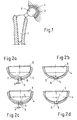
- FIGS. 2a, 2b a cylindrical (see FIGS. 2a, 2b ) or conical guide pin (see Figures 2c, 2d ) arranged on the pole of the respective socket insert 3.
- the guide pin is inserted at the onset of the socket insert 3 in a correspondingly shaped guide bore 6 at the bottom of the acetabular cup 4 and thus prevents tilting of the socket insert 3.
- Die Figures 2a, 2b, 2c, 2d show a socket insert 3 with cylindrical (top) and conical (bottom) guide pin 5 at the back pole.
- the gap width s determines how exactly the socket insert 3 is guided during insertion into the acetabular cup 4.
- the guide length of the guide pin 5 is usually extremely low - especially at the moment of insertion of the socket insert when the located within the guide bore length of the guide pin still low, the need for leadership for a functional insertion of the socket insert however, it is highest.
- the guide length increases with increasing insertion of the socket insert in the acetabulum, with increasing improvement of the guiding effect.
- it also takes the leadership effect of the conical clamping connection between pan insert and Acetabular cup, which increasingly reduces the need for guidance through the guide pin.
- the need for guidance and guidance accuracy of the guide pin are thus in inverse proportion.
- the invention has the object of providing a hip joint prosthesis, a socket insert and a hip socket according to the preambles of claims 1, 6 and 7 educate so that a functional insertion of the socket insert in the acetabulum with high guidance accuracy is made possible even under difficult conditions.
- the guide pin is formed in an inwardly tapering manner, the diameter of the guide pin being smaller at the end facing the pole than at the end of the guide pin facing away from the pole.
- an embodiment according to the invention is characterized in that the guide bore is formed in an inwardly tapered manner, wherein the diameter of the guide bore is smaller at the end facing the interior or base of the acetabular cup than at the end of the guide bore facing away from the interior.
- Another embodiment of the invention is characterized in that the guide bore is cylindrical.
- the guide bore may also consist of preferably two sections, wherein in the first section, the guide bore is cylindrical and tapered in the second section tapered.
- the first section is arranged on the end of the guide bore facing the interior of the acetabular cup.
- An inventive socket insert for a hip joint prosthesis with a pole arranged on the conical guide pin for insertion into a corresponding guide bore in a hip socket is shown in claim 6.
- a hip socket according to the invention for a hip joint prosthesis with a conical guide bore arranged at the base of the acetabulum for receiving a guide pin of a socket insert is shown in claim 7.
- the inventive embodiments of the socket insert for a hip joint prosthesis which is provided with a guide pin, which is designed inversely-tapered, a tilted insertion of the socket insert is avoided in the acetabulum, since already at the beginning of the insertion process, a guide in the insertion movement of the socket insert ,
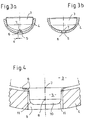
- FIGS. 3a, 3b show a socket insert 3 with inverse-conical pin 5 at the rear pole 7.
- the smallest gap width s leads to high guiding effect at low tilt risk.
- Another positive effect of the inverse-conical shape of the pin 5 occurs in the design of radii of curvature on the component. This is necessary when using brittle materials, e.g. if the socket insert 3 according to the invention consists of a ceramic material. In such a case, the edges 9 of the pin 5 must be rounded in order to reduce notch stresses and edge breakouts.
- FIG. 4 shows a socket insert with cylindrical pin 5 and rounded edges 9, tolerance analysis with respect to largest and smallest edge radius (dashed) shows collision with acetabulum in the region of the through hole at the largest radius.
- FIG. 5 shows a socket insert with inverse-conical pin and rounded edges 9, tolerance analysis with respect to the largest and smallest edge radius (dashed) has no collision with the acetabular cup.
- Pins and guide pins are two terms that, however, refer to the same item.
- the pole 7 remote from the end portion 10 of the guide pin 5 or pin is rounded, ie, the inwardly-conically extending guide pin 5 has a rounded end portion 10 (see FIGS. 4 and 5 ). As a result, inter alia, the insertion into the guide bore 6 is facilitated.
Landscapes
- Health & Medical Sciences (AREA)
- Orthopedic Medicine & Surgery (AREA)
- Cardiology (AREA)
- Oral & Maxillofacial Surgery (AREA)
- Transplantation (AREA)
- Engineering & Computer Science (AREA)
- Biomedical Technology (AREA)
- Heart & Thoracic Surgery (AREA)
- Vascular Medicine (AREA)
- Life Sciences & Earth Sciences (AREA)
- Animal Behavior & Ethology (AREA)
- General Health & Medical Sciences (AREA)
- Public Health (AREA)
- Veterinary Medicine (AREA)
- Prostheses (AREA)
Description
- Die Erfindung beschreibt eine Hüftgelenkprothese mit einem Pfanneneinsatz und einer Hüftpfanne, wobei auf dem Pol des Pfanneneinsatzes ein konischer Führungszapfen und am Grund der Hüftpfanne eine Führungsbohrung angeordnet sind und sich im Einbauzustand des Pfanneneinsatzes in der Hüftpfanne der Führungszapfen in der Führungsbohrung befindet.
- Im Markt existieren eine Vielzahl von Prothesen-Systemen zum Ersatz des natürlichen Hüftgelenkes. Diese bestehen in der Regel aus einem Schaft 1, gekoppelt mit einem Kugelkopf 2, und einer Hüftpfanne 4, gekoppelt mit einem Pfanneneinsatz 3, siehe
Figur 1 . Schaft 1 und Hüftpfanne 4 sind mit dem Körper durch Einwachsen in den Oberschenkel- bzw. Beckenknochen verbunden und sind Träger für den Kugelkopf 2 bzw. Pfanneneinsatz 3. Der Kugelkopf 2 ist in der Kalotte des Pfanneneinsatzes 3 drehbar gelagert - Freiheitsgrad: 1. Schaft 1 und Kugelkopf 2 werden dabei in der Regel durch konische Klemmung gekoppelt. Dies trifft zumeist auf Pfanneneinsatz 3 und Hüftpfanne 4 zu, die auch in der Regel durch konische Klemmung gekoppelt sind.Figur 1 zeigt eine Hüftprothese, bestehend aus Schaft 1, Kugelkopf 2, Hüftpfanne 3 und Pfanneneinsatz 4. - Während des Einsetzvorgangs insbesondere dünnwandiger Metallschalen in den Beckenknochen kann es zu Verformungen der Metallschalen im Bereich des Klemmkonus kommen. Dadurch wird das korrekte, funktionsgerechte Einsetzen des konisch geklemmten Pfanneneinsatzes erschwert. Im Extremfall tritt ein Verklemmen von Pfanneneinsatz und Hüftpfanne bei verkippter Lage des Pfanneneinsatzes in der Hüftpfanne auf. Die Verkippung des Pfanneneinsatzes ändert die Lastsituation und führt zu Punktlasten, welche sowohl die Dauerhaftigkeit der Klemmverbindung als auch die Lebensdauer des Pfanneneinsatzes an sich erheblich mindern können.
- Weiterhin besteht gerade bei minimal-invasiven Operationstechniken in der Regel keine ausreichende Sicht auf das Operationsfeld, um zum Beispiel das korrekte Einsetzen des Pfanneneinsatzes in die Hüftpfanne unter visueller Kontrolle durchzuführen. Die konische Klemmung des Pfanneneinsatzes in der Hüftpfanne wirkt beim Einsetzen selbstzentrierend. Diese Führung des Pfanneneinsatzes beim Einsetzen in die Hüftpfanne wirkt aber nur bei geringen initialen Verkippungswinkeln. Tritt durch mangelnde Sicht des Operateurs eine stärkere initiale Verkippung auf, versagt die Selbstzentrierung und es tritt ein verkipptes Verklemmen mit den oben beschriebenen Folgen auf.
- In der Vergangenheit wurde deshalb bei verschiedenen Pfanneneinsätzen eine zusätzliche Führung des Pfanneneinsatzes während der Einsetzbewegung realisiert. Zu diesem Zweck ist auf dem Pol des jeweiligen Pfanneneinsatzes 3 ein zylindrischer (siehe
Figuren 2a, 2b ) oder konischer Führungszapfen (sieheFiguren 2c, 2d ) angeordnet. Der Führungszapfen wird beim Einsetzen des Pfanneneinsatzes 3 in eine entsprechend geformte Führungsbohrung 6 am Grund der Hüftpfanne 4 eingeführt und verhindert somit ein Verkippen des Pfanneneinsatzes 3. DieFiguren 2a, 2b, 2c, 2d zeigen einen Pfanneneinsatz 3 mit zylindrischem (oben) bzw. konischem (unten) Führungszapfen 5 am rückseitigen Pol. Die Spaltbreite s (sieheFiguren 2a, 2c ) bestimmt, wie genau der Pfanneneinsatz 3 beim Einsetzen in die Hüftpfanne 4 geführt wird. - Aufgrund des geringen Bauraumes für Führungszapfen 5 und Führungsbohrung 6 ist die Führungslänge des Führungszapfens 5 in der Regel äußerst gering - insbesondere im Moment des Einsetzens des Pfanneneinsatzes, wenn die innerhalb der Führungsbohrung befindliche Länge des Führungszapfens noch gering, der Führungsbedarf für ein funktionsgerechtes Einsetzen des Pfanneneinsatzes allerdings am höchsten ist. Die Führungslänge steigt mit zunehmendem Einsetzen des Pfanneneinsatzes in die Hüftpfanne an, bei zunehmender Verbesserung der Führungswirkung. Allerdings nimmt dabei ebenfalls die Führungswirkung der konischen Klemmverbindung zwischen Pfanneneinsatz und Hüftpfanne zu, was die Notwendigkeit der Führung durch den Führungszapfen zunehmend mindert. Die Notwendigkeit der Führung und der Führungsgenauigkeit des Führungszapfens stehen somit in umgekehrtem Verhältnis.
- Um ein Verkanten der Führung zu vermeiden, muss ein entsprechend großer Führungsspalt s realisiert werden. Weiterhin wird aufgrund der Durchmessertoleranzen von Führungszapfen und Führungsbohrung eine notwendige Mindestgröße des Führungsspaltes vorgegeben. Mit zunehmender Größe des Führungsspaltes sinkt allerdings die Führungsgenauigkeit zwischen Führungszapfen und Führungsbohrung und das Risiko der Verkippung des Pfanneneinsatzes in der Hüftpfanne steigt.
- Der Erfindung liegt die Aufgabe zugrunde, eine Hüftgelenkprothese, einen Pfanneneinsatz und eine Hüftpfanne nach den Oberbegriffen der Ansprüche 1, 6 und 7 so weiterzubilden, dass ein funktionsgerechtes Einsetzen des Pfanneneinsatzes in die Hüftpfanne mit hoher Führungsgenauigkeit auch unter erschwerten Bedingungen ermöglicht wird.
- Erfindungsgemäß wird diese Aufgabe durch die Merkmale der Ansprüche 1, 6 und 7 gelöst.
- Erfindungsgemäß ist der Führungszapfen invers-konisch zulaufend ausgebildet, wobei an dem zum Pol gewandten Ende der Durchmesser des Führungszapfens geringer ist als an dem vom Pol abgewandten Ende des Führungszapfens.
- Dadurch, dass auf dem Pol des Pfanneneinsatzes ein Führungszapfen ausgebildet ist, welcher invers-konisch zuläuft und welcher in eine zylindrische oder ebenfalls invers-konische Führungsbohrung im Hüftpfannengrund eingesetzt wird, wird die theoretische Führungslänge des Systems zu null und das Prinzip der Ausbildung einer klassischen Führung verlassen. Eine Führung und somit Unterstützung des Einsetzens des Pfanneneinsatzes zur Vermeidung der verkippten Lage erfolgt aber dennoch. Weiterhin sind extrem kleine Führungsspalte und somit eine hohe Führungsgenauigkeit realisierbar. Insbesondere wird gleich zu Beginn des Einsetzens des Pfanneneinsatzes in die Hüftpfanne der geringe Führungsspalt und damit die hohe Führungsgenauigkeit realisiert.
- Wie dargestellt, zeichnet sich eine erfindungsgemässe Ausgestaltung dadurch aus, dass die Führungsbohrung invers-konisch zulaufend ausgebildet ist, wobei an dem zum Inneren bzw. Grund der Hüftpfanne gewandten Ende der Durchmesser der Führungsbohrung geringer ist als an dem vom Inneren abgewandten Ende der Führungsbohrung.
- Eine andere erfindungsgemässe Ausgestaltung zeichnet sich dadurch aus, dass die Führungsbohrung zylindrisch ausgebildet ist.
- Die Führungsbohrung kann auch aus bevorzugt zwei Abschnitten bestehen, wobei im ersten Abschnitt die Führungsbohrung zylindrisch und im zweiten Abschnitt invers-konisch zulaufend ausgebildet ist.
- Vorteilhaft ist der erste Abschnitt an dem zum Inneren der Hüftpfanne gewandten Ende der Führungsbohrung angeordnet.
- Ein erfindungsgemäßer Pfanneneinsatz für eine Hüftgelenkprothese mit einem am Pol angeordneten konischen Führungszapfen zur Einführung in eine entsprechende Führungsbohrung in einer Hüftpfanne ist in Anspruch 6 gezeigt.
- Ein erfindungsgemäße Hüftpfanne für eine Hüftgelenkprothese mit einer am Grund der Hüftpfanne angeordneten konischen Führungsbohrung zur Aufnahme eines Führungszapfens eines Pfanneneinsatzes ist in Anspruch 7 dargestellt.
- Durch die erfindungsgemäßen Ausbildungen des Pfanneneinsatz für eine Hüftgelenkprothese, der mit einem Führungszapfen versehen ist, welcher invers-konisch zulaufend gestaltet ist, ist ein verkipptes Einsetzen des Pfanneneinsatzes in die Hüftpfanne vermieden, da bereits zu Beginn des Einsetzvorgangs eine Führung bei der Einsetzbewegung des Pfanneneinsatzes erfolgt.
- Bei zylindrischer Führungsbohrung bleibt der geringe Führungsspalt über die gesamte Länge der Führung konstant, während er bei invers-konischer Führungsbohrung mit zunehmender Einsetztiefe des Pfanneneinsatzes zunimmt. Die damit verbundene Abnahme der Führungsgenauigkeit entspricht allerdings auch der ebenfalls abnehmenden Notwendigkeit zur Führung, da die konische Klemmung zunehmend die Führungswirkung realisiert. Die
Figuren 3a, 3b zeigen einen Pfanneneinsatz 3 mit invers-konischem Zapfen 5 am rückseitigen Pol 7. Die geringste Spaltbreite s führt zu hoher Führungswirkung bei geringem Verkantungsrisiko. - Ein weiterer positiver Effekt der invers-konischen Form des Zapfens 5 tritt bei Gestaltung von Verrundungsradien am Bauteil auf. Dies ist bei Verwendung spröder Werkstoffe notwendig, z.B. wenn der Pfanneneinsatz 3 erfindungsgemäss aus einem keramischen Werkstoff besteht. In solch einem Fall müssen die Kanten 9 des Zapfens 5 verrundet werden, um Kerbspannungen und Kantenausbrüche zu mindern.
- Führt man an Verrundungsradien an zylindrischen oder konischen Zapfen Toleranzanalysen bzgl. größtem und kleinstem zulässigen Verrundungsradius durch, zeigen sich unter Umständen Kollisionen mit der Bohrung im Pfannenpol. Diese können nur durch Einschränkung von Toleranzen oder Reduktion des Zapfendurchmessers vermieden werden, siehe
Figur 4 . Toleranzeinschränkungen erhöhen in der Regel die Herstellkosten. Die Reduktion des Zapfendurchmessers erhöht die Spaltbreite s und mindert die Führungswirkung des Zapfens 5 beim Einsetzen des Pfanneneinsatzes.Figur 4 zeigt einen Pfanneneinsatz mit zylindrischem Zapfen 5 und verrundeten Kanten 9, Toleranzanalyse bzgl. größtem und kleinstem Kantenradius (gestrichelt) zeigt Kollision mit Hüftpfanne im Bereich der Durchgangsbohrung bei größtem Radius. - Bei invers-konischer Form des Zapfens 5 führt die Verjüngung des Zapfens zu einem vergrößerten Bauraum am einsatzseitigen Zapfenende. Toleranzanalysen der Kantenverrundung führen somit bei gleichen Werten zu einem größeren Abstand zur Durchgangsbohrung bzw. Führungsbohrung 6 der Hüftpfannen 4. Die Führungswirkung des Zapfens bleibt erhalten, ohne dass unerwünschte Kollisionen zwischen den Bauteilen auftreten, siehe
Figur 5. Figur 5 zeigt einen Pfanneneinsatz mit invers-konischem Zapfen und verrundeten Kanten 9, Toleranzanalyse bzgl. größtem und kleinstem Kantenradius (gestrichelt) weist keine Kollision mit der Hüftpfanne auf. Zapfen und Führungszapfen sind zwei Begriffe, die jedoch denselben Gegenstand bezeichnen. - Der dem Pol 7 abgewandte Endbereich 10 des Führungszapfens 5 bzw. Zapfens ist abgerundet, d.h. der invers-konisch verlaufende Führungszapfen 5 weist einen abgerundeten Endbereich 10 auf (siehe
Figuren 4 und5 ). Hierdurch wird unter anderem das Einsetzen in die Führungsbohrung 6 erleichtert.
Claims (8)
- Hüftgelenkprothese mit einem Pfanneneinsatz (3) und einer Hüftpfanne (4), wobei auf dem Pol (7) des Pfanneneinsatzes (3) ein Führungszapfen (5) und am Grund der Hüftpfanne (4) eine Öffnung angeordnet sind und sich im Einbauzustand des Pfanneneinsatzes (3) in der Hüftpfanne (4) der Führungszapfen (5) in der öffnung (6) befindet, dadurch gekennzeichnet, dass der Pfanneneinsatz (3) aus einer Keramik besteht, der Führungszapfen (5) invers-konisch zulaufend ausgebildet ist, wobei an dem zum Pol (7) gewandten Ende der Durchmesser des Führungszapfens (5) geringer ist als an dem vom Pol (7) abgewandten Ende (8) des Führungszapfens (5), dass der Führungszapten (5) verrundete kanten (9,11) aufweist, und dass die Öffnung (6) eine Führungsbohrung ist.
- Hüftgelenkprothese nach Anspruch 1, dadurch gekennzeichnet, dass die Führungsbohrung (6) invers-konisch zulaufend ausgebildet ist, wobei an dem zum Inneren bzw. Grund der Hüftpfanne (4) gewandten Ende der Durchmesser der Führungsbohrung (6) geringer ist als an dem vom Inneren abgewandten Ende der Führungsbohrung (6).
- Hüftgelenkprothese nach Anspruch 1, dadurch gekennzeichnet, dass die Führungsbohrung (6) zylindrisch ausgebildet ist.
- Hüftgelenkprothese nach Anspruch 1 oder 2, dadurch gekennzeichnet, dass die Führungsbohrung (6) aus zwei Abschnitten besteht, wobei im ersten Abschnitt die Führungsbohrung (6) zylindrisch und im zweiten Abschnitt invers-konisch zulaufend ausgebildet ist.
- Hüftgelenkprothese nach Anspruch 4, dadurch gekennzeichnet, dass der erste Abschnitt an dem zum Inneren der Hüftpfanne (4) gewandten Ende der Führungsbohrung (6) angeordnet ist.
- Pfanneneinsatz (3) für eine Hüftgelenkprothese mit einem am Pol (7) angeordneten Führungszapfen (5) zur Einführung in eine entsprechende Führungsbohrung (6) in einer Hüftpfanne (4), dadurch gekennzeichnet, dass der Pfanneneinsatz (3) aus einer Keramik besteht und der Führungszapfen (5) invers-konisch zulaufend ausgebildet ist, wobei an dem zum Pol (7) gewandten Ende der Durchmesser des Führungszapfens (5) geringer ist als an dem vom Pol (7) abgewandten Ende des Führungszapfens (5), und dass der Führungszapfen (5) verrundete Kanten (9, 11) aufweist.
- Hüftpfanne (4) für eine Hüftgelenkprothese mit einer am Grund der Hüftpfanne (4) angeordneten Öffnung zur Aufnahme eines Führungszapfens (5) eines Pfanneneinsatzes (3), dadurch gekennzeichnet, dass die Öffnung eine konische Führungsbohrung (6) ist, die Führungsbohrung (6) invers-konisch zulaufend ausgebildet ist, wobei an dem zum Inneren der Hüftpfanne (4) gewandten Ende der Durchmesser der Führungsbohrung (6) geringer ist als an dem vom Inneren abgewandten Ende der Führungsbohrung (6).
- Hüftgelenkprothese nach einem der Ansprüche 1 bis 5, oder Pfanneneinsatz nach Anspruch 6, dadurch gekennzeichnet, dass der Führungszapfen (5) einen abgerundeten Endbereich (10) aufweist.
Applications Claiming Priority (2)
| Application Number | Priority Date | Filing Date | Title |
|---|---|---|---|
| DE102009000771 | 2009-02-11 | ||
| PCT/EP2010/051371 WO2010091995A1 (de) | 2009-02-11 | 2010-02-04 | Keramischer pfanneneinsatz mit invers-konischem führungszapfen |
Publications (2)
| Publication Number | Publication Date |
|---|---|
| EP2395946A1 EP2395946A1 (de) | 2011-12-21 |
| EP2395946B1 true EP2395946B1 (de) | 2016-08-24 |
Family
ID=41819673
Family Applications (1)
| Application Number | Title | Priority Date | Filing Date |
|---|---|---|---|
| EP10702491.1A Active EP2395946B1 (de) | 2009-02-11 | 2010-02-04 | Keramischer pfanneneinsatz mit invers-konischem führungszapfen |
Country Status (7)
| Country | Link |
|---|---|
| US (2) | US20120101590A1 (de) |
| EP (1) | EP2395946B1 (de) |
| JP (1) | JP5766615B2 (de) |
| KR (1) | KR101697943B1 (de) |
| CN (1) | CN102341064B (de) |
| DE (1) | DE102010001600A1 (de) |
| WO (1) | WO2010091995A1 (de) |
Families Citing this family (9)
| Publication number | Priority date | Publication date | Assignee | Title |
|---|---|---|---|---|
| US8123815B2 (en) | 2008-11-24 | 2012-02-28 | Biomet Manufacturing Corp. | Multiple bearing acetabular prosthesis |
| US8308810B2 (en) | 2009-07-14 | 2012-11-13 | Biomet Manufacturing Corp. | Multiple bearing acetabular prosthesis |
| FR2950525B1 (fr) * | 2009-09-28 | 2013-05-10 | Thomas Gradel | Cotyle prothetique de hanche a fixation externe |
| ITUD20120179A1 (it) * | 2012-10-24 | 2014-04-25 | Limacorporate Spa | Protesi acetabolare e relativo procedimento di fabbricazione e di assemblaggio |
| ITUD20130074A1 (it) | 2013-05-24 | 2014-11-25 | Limacorporate Spa | Protesi acetabolare |
| USD794503S1 (en) * | 2016-03-26 | 2017-08-15 | Kamal Siegel | Figurine neck joint |
| EP3398558A1 (de) | 2017-05-02 | 2018-11-07 | Carlo Andretta | Körperperfusionssystem |
| US12083018B2 (en) | 2020-09-18 | 2024-09-10 | Globus Medical, Inc. | Hip arthroplasty implants |
| US12053383B2 (en) | 2020-09-18 | 2024-08-06 | Globus Medical Inc. | Hip arthroplasty implants |
Family Cites Families (15)
| Publication number | Priority date | Publication date | Assignee | Title |
|---|---|---|---|---|
| FR2661605B1 (fr) * | 1990-05-07 | 1997-11-28 | Bouvet Jean Claude | Cotyle pour prothese rotulienne notamment pour prothese du type coxo-femoral. |
| DE9014542U1 (de) * | 1990-10-20 | 1991-01-03 | Howmedica GmbH, 2314 Schönkirchen | Schalenelement zur Aufnahme einer Gelenkendoprothese |
| US5326368A (en) | 1992-09-22 | 1994-07-05 | Howmedica, Inc. | Modular acetabular cup |
| ATE188605T1 (de) * | 1993-08-30 | 2000-01-15 | Sulzer Orthopaedie Ag | Element zur vorübergehenden erhöhung der steifigkeit einer orthopädischen prothese |
| US5571198A (en) * | 1994-01-21 | 1996-11-05 | David A. Drucker | Acetabular shell with selectively available bone screw holds |
| WO2000007526A1 (de) * | 1998-08-07 | 2000-02-17 | Eska Implants Gmbh & Co. | Kugelkopfgelenk für ein künstliches hüftgelenk |
| US6152962A (en) * | 1998-12-30 | 2000-11-28 | Depuy Orthopaedics, Inc. | Acetabular cup with plug for screw holes |
| CA2378135A1 (en) * | 1999-07-15 | 2001-01-25 | Ceramtec Ag Innovative Ceramic Engineering | Ceramic sandwich insert for an artificial hip joint |
| CN2386789Y (zh) * | 1999-07-22 | 2000-07-12 | 马忠泰 | 非骨水泥金属髋臼 |
| US6503281B1 (en) * | 2000-08-25 | 2003-01-07 | Thomas H. Mallory | Total hip replacement |
| US20030049328A1 (en) * | 2001-03-02 | 2003-03-13 | Dalal Paresh S. | Porous beta-tricalcium phosphate granules and methods for producing same |
| FR2829687B1 (fr) * | 2001-09-20 | 2003-12-05 | Smile Fit | Cotyle prothetique de la hanche |
| US7294150B1 (en) * | 2003-12-08 | 2007-11-13 | Orthopedic Source, Inc. | Liner for acetabular cup |
| US20070203583A1 (en) * | 2006-02-28 | 2007-08-30 | Biomet Manufacturing Corp. | Method and apparatus for aligning a taper lock connection |
| US8123815B2 (en) * | 2008-11-24 | 2012-02-28 | Biomet Manufacturing Corp. | Multiple bearing acetabular prosthesis |
-
2010
- 2010-02-04 US US13/147,616 patent/US20120101590A1/en not_active Abandoned
- 2010-02-04 KR KR1020117021123A patent/KR101697943B1/ko active Active
- 2010-02-04 JP JP2011548686A patent/JP5766615B2/ja active Active
- 2010-02-04 CN CN201080007383.5A patent/CN102341064B/zh active Active
- 2010-02-04 DE DE102010001600A patent/DE102010001600A1/de not_active Withdrawn
- 2010-02-04 EP EP10702491.1A patent/EP2395946B1/de active Active
- 2010-02-04 WO PCT/EP2010/051371 patent/WO2010091995A1/de not_active Ceased
-
2017
- 2017-06-02 US US15/612,847 patent/US20170281433A1/en not_active Abandoned
Also Published As
| Publication number | Publication date |
|---|---|
| JP5766615B2 (ja) | 2015-08-19 |
| WO2010091995A1 (de) | 2010-08-19 |
| KR20120013934A (ko) | 2012-02-15 |
| US20170281433A1 (en) | 2017-10-05 |
| DE102010001600A1 (de) | 2010-08-12 |
| JP2012517250A (ja) | 2012-08-02 |
| CN102341064A (zh) | 2012-02-01 |
| EP2395946A1 (de) | 2011-12-21 |
| CN102341064B (zh) | 2014-09-17 |
| US20120101590A1 (en) | 2012-04-26 |
| KR101697943B1 (ko) | 2017-01-19 |
Similar Documents
| Publication | Publication Date | Title |
|---|---|---|
| WO2010091995A1 (de) | Keramischer pfanneneinsatz mit invers-konischem führungszapfen | |
| EP2335656B1 (de) | Zwischenwirbelimplantat | |
| EP0795306B1 (de) | Modulares Knochenimplantat mit Pfanne und Stiften | |
| EP0583711B1 (de) | Kugelkopfendoprothese | |
| EP0388745B1 (de) | Hüftgelenkspfanne zur zementfreien Implantation in das Acetabulum des Hüftbeines | |
| EP0442330B1 (de) | Kniegelenk-Endoprothese | |
| WO1997018776A1 (de) | Modulare endoprothese | |
| WO1999048446A1 (de) | Klemmsitz-verbindung zwischen prothesenkomponenten von gelenk-prothesen | |
| EP2049046B1 (de) | Asymmetrische gestaltung von hüftpfannen zur verringerung der pfannendeformationen | |
| EP2499999B1 (de) | Wirbelsäulenimpantat mit Ringen | |
| EP1150625A1 (de) | Hüftgelenkpfanne mit kopplungselement zwischen pfannengehäuse und pfanneneinsatz | |
| WO2002064066A2 (de) | Implantierbare pfanne für hüftgelenk-endoprothesen | |
| DE19502503C1 (de) | Modulares Knochenimplantat mit Pfanne und Stiften | |
| WO2008003597A1 (de) | Implantat | |
| EP3544551B1 (de) | Zwischensegment für eine gelenkkomponente | |
| EP4231946B1 (de) | Schraubenelement optimiert für den 3d-druck | |
| EP3893778B1 (de) | Teilweise blockierte pedikelschraube | |
| CH702417B1 (de) | Verankerungsschale für eine künstliche Hüftpfanne. | |
| EP3380047B1 (de) | Gelenkpfannenimplantat | |
| CH715848A2 (de) | Modulare Hüftpfannenprothese. | |
| DE102008064176B4 (de) | Polyaxial ausrichtbares zapfenförmiges Stabilisierungselement für Endoprothesen | |
| DE29805344U1 (de) | Endoprothese mit einem Verankerungsschaft | |
| EP1404242A1 (de) | Pedikelschraubenanordnung | |
| DE4007789A1 (de) | Hueftgelenkspfanne zur zementfreien implantation in das acetabulum des hueftbeines | |
| EP2014260A1 (de) | Mehrteiliges oder modulares orthopädisches und traumatologisches Implantat |
Legal Events
| Date | Code | Title | Description |
|---|---|---|---|
| PUAI | Public reference made under article 153(3) epc to a published international application that has entered the european phase |
Free format text: ORIGINAL CODE: 0009012 |
|
| 17P | Request for examination filed |
Effective date: 20110912 |
|
| AK | Designated contracting states |
Kind code of ref document: A1 Designated state(s): AT BE BG CH CY CZ DE DK EE ES FI FR GB GR HR HU IE IS IT LI LT LU LV MC MK MT NL NO PL PT RO SE SI SK SM TR |
|
| DAX | Request for extension of the european patent (deleted) | ||
| GRAP | Despatch of communication of intention to grant a patent |
Free format text: ORIGINAL CODE: EPIDOSNIGR1 |
|
| INTG | Intention to grant announced |
Effective date: 20150929 |
|
| GRAS | Grant fee paid |
Free format text: ORIGINAL CODE: EPIDOSNIGR3 |
|
| GRAA | (expected) grant |
Free format text: ORIGINAL CODE: 0009210 |
|
| AK | Designated contracting states |
Kind code of ref document: B1 Designated state(s): AT BE BG CH CY CZ DE DK EE ES FI FR GB GR HR HU IE IS IT LI LT LU LV MC MK MT NL NO PL PT RO SE SI SK SM TR |
|
| REG | Reference to a national code |
Ref country code: GB Ref legal event code: FG4D Free format text: NOT ENGLISH |
|
| REG | Reference to a national code |
Ref country code: CH Ref legal event code: EP |
|
| REG | Reference to a national code |
Ref country code: AT Ref legal event code: REF Ref document number: 822360 Country of ref document: AT Kind code of ref document: T Effective date: 20160915 |
|
| REG | Reference to a national code |
Ref country code: IE Ref legal event code: FG4D Free format text: LANGUAGE OF EP DOCUMENT: GERMAN |
|
| REG | Reference to a national code |
Ref country code: DE Ref legal event code: R096 Ref document number: 502010012255 Country of ref document: DE |
|
| REG | Reference to a national code |
Ref country code: LT Ref legal event code: MG4D |
|
| REG | Reference to a national code |
Ref country code: NL Ref legal event code: MP Effective date: 20160824 |
|
| PG25 | Lapsed in a contracting state [announced via postgrant information from national office to epo] |
Ref country code: LT Free format text: LAPSE BECAUSE OF FAILURE TO SUBMIT A TRANSLATION OF THE DESCRIPTION OR TO PAY THE FEE WITHIN THE PRESCRIBED TIME-LIMIT Effective date: 20160824 Ref country code: NL Free format text: LAPSE BECAUSE OF FAILURE TO SUBMIT A TRANSLATION OF THE DESCRIPTION OR TO PAY THE FEE WITHIN THE PRESCRIBED TIME-LIMIT Effective date: 20160824 Ref country code: NO Free format text: LAPSE BECAUSE OF FAILURE TO SUBMIT A TRANSLATION OF THE DESCRIPTION OR TO PAY THE FEE WITHIN THE PRESCRIBED TIME-LIMIT Effective date: 20161124 Ref country code: HR Free format text: LAPSE BECAUSE OF FAILURE TO SUBMIT A TRANSLATION OF THE DESCRIPTION OR TO PAY THE FEE WITHIN THE PRESCRIBED TIME-LIMIT Effective date: 20160824 Ref country code: FI Free format text: LAPSE BECAUSE OF FAILURE TO SUBMIT A TRANSLATION OF THE DESCRIPTION OR TO PAY THE FEE WITHIN THE PRESCRIBED TIME-LIMIT Effective date: 20160824 |
|
| REG | Reference to a national code |
Ref country code: FR Ref legal event code: PLFP Year of fee payment: 8 |
|
| PG25 | Lapsed in a contracting state [announced via postgrant information from national office to epo] |
Ref country code: ES Free format text: LAPSE BECAUSE OF FAILURE TO SUBMIT A TRANSLATION OF THE DESCRIPTION OR TO PAY THE FEE WITHIN THE PRESCRIBED TIME-LIMIT Effective date: 20160824 Ref country code: LV Free format text: LAPSE BECAUSE OF FAILURE TO SUBMIT A TRANSLATION OF THE DESCRIPTION OR TO PAY THE FEE WITHIN THE PRESCRIBED TIME-LIMIT Effective date: 20160824 Ref country code: PT Free format text: LAPSE BECAUSE OF FAILURE TO SUBMIT A TRANSLATION OF THE DESCRIPTION OR TO PAY THE FEE WITHIN THE PRESCRIBED TIME-LIMIT Effective date: 20161226 Ref country code: GR Free format text: LAPSE BECAUSE OF FAILURE TO SUBMIT A TRANSLATION OF THE DESCRIPTION OR TO PAY THE FEE WITHIN THE PRESCRIBED TIME-LIMIT Effective date: 20161125 Ref country code: SE Free format text: LAPSE BECAUSE OF FAILURE TO SUBMIT A TRANSLATION OF THE DESCRIPTION OR TO PAY THE FEE WITHIN THE PRESCRIBED TIME-LIMIT Effective date: 20160824 |
|
| PG25 | Lapsed in a contracting state [announced via postgrant information from national office to epo] |
Ref country code: RO Free format text: LAPSE BECAUSE OF FAILURE TO SUBMIT A TRANSLATION OF THE DESCRIPTION OR TO PAY THE FEE WITHIN THE PRESCRIBED TIME-LIMIT Effective date: 20160824 Ref country code: EE Free format text: LAPSE BECAUSE OF FAILURE TO SUBMIT A TRANSLATION OF THE DESCRIPTION OR TO PAY THE FEE WITHIN THE PRESCRIBED TIME-LIMIT Effective date: 20160824 |
|
| REG | Reference to a national code |
Ref country code: DE Ref legal event code: R097 Ref document number: 502010012255 Country of ref document: DE |
|
| PG25 | Lapsed in a contracting state [announced via postgrant information from national office to epo] |
Ref country code: CZ Free format text: LAPSE BECAUSE OF FAILURE TO SUBMIT A TRANSLATION OF THE DESCRIPTION OR TO PAY THE FEE WITHIN THE PRESCRIBED TIME-LIMIT Effective date: 20160824 Ref country code: BE Free format text: LAPSE BECAUSE OF NON-PAYMENT OF DUE FEES Effective date: 20170228 Ref country code: SK Free format text: LAPSE BECAUSE OF FAILURE TO SUBMIT A TRANSLATION OF THE DESCRIPTION OR TO PAY THE FEE WITHIN THE PRESCRIBED TIME-LIMIT Effective date: 20160824 Ref country code: BG Free format text: LAPSE BECAUSE OF FAILURE TO SUBMIT A TRANSLATION OF THE DESCRIPTION OR TO PAY THE FEE WITHIN THE PRESCRIBED TIME-LIMIT Effective date: 20161124 Ref country code: PL Free format text: LAPSE BECAUSE OF FAILURE TO SUBMIT A TRANSLATION OF THE DESCRIPTION OR TO PAY THE FEE WITHIN THE PRESCRIBED TIME-LIMIT Effective date: 20160824 Ref country code: SM Free format text: LAPSE BECAUSE OF FAILURE TO SUBMIT A TRANSLATION OF THE DESCRIPTION OR TO PAY THE FEE WITHIN THE PRESCRIBED TIME-LIMIT Effective date: 20160824 Ref country code: DK Free format text: LAPSE BECAUSE OF FAILURE TO SUBMIT A TRANSLATION OF THE DESCRIPTION OR TO PAY THE FEE WITHIN THE PRESCRIBED TIME-LIMIT Effective date: 20160824 |
|
| PLBE | No opposition filed within time limit |
Free format text: ORIGINAL CODE: 0009261 |
|
| STAA | Information on the status of an ep patent application or granted ep patent |
Free format text: STATUS: NO OPPOSITION FILED WITHIN TIME LIMIT |
|
| 26N | No opposition filed |
Effective date: 20170526 |
|
| PG25 | Lapsed in a contracting state [announced via postgrant information from national office to epo] |
Ref country code: SI Free format text: LAPSE BECAUSE OF FAILURE TO SUBMIT A TRANSLATION OF THE DESCRIPTION OR TO PAY THE FEE WITHIN THE PRESCRIBED TIME-LIMIT Effective date: 20160824 |
|
| PG25 | Lapsed in a contracting state [announced via postgrant information from national office to epo] |
Ref country code: MC Free format text: LAPSE BECAUSE OF FAILURE TO SUBMIT A TRANSLATION OF THE DESCRIPTION OR TO PAY THE FEE WITHIN THE PRESCRIBED TIME-LIMIT Effective date: 20160824 |
|
| GBPC | Gb: european patent ceased through non-payment of renewal fee |
Effective date: 20170204 |
|
| REG | Reference to a national code |
Ref country code: IE Ref legal event code: MM4A |
|
| PG25 | Lapsed in a contracting state [announced via postgrant information from national office to epo] |
Ref country code: LU Free format text: LAPSE BECAUSE OF NON-PAYMENT OF DUE FEES Effective date: 20170204 |
|
| REG | Reference to a national code |
Ref country code: BE Ref legal event code: MM Effective date: 20170228 |
|
| REG | Reference to a national code |
Ref country code: FR Ref legal event code: PLFP Year of fee payment: 9 |
|
| PG25 | Lapsed in a contracting state [announced via postgrant information from national office to epo] |
Ref country code: IE Free format text: LAPSE BECAUSE OF NON-PAYMENT OF DUE FEES Effective date: 20170204 Ref country code: GB Free format text: LAPSE BECAUSE OF NON-PAYMENT OF DUE FEES Effective date: 20170204 |
|
| PG25 | Lapsed in a contracting state [announced via postgrant information from national office to epo] |
Ref country code: MT Free format text: LAPSE BECAUSE OF FAILURE TO SUBMIT A TRANSLATION OF THE DESCRIPTION OR TO PAY THE FEE WITHIN THE PRESCRIBED TIME-LIMIT Effective date: 20160824 |
|
| PG25 | Lapsed in a contracting state [announced via postgrant information from national office to epo] |
Ref country code: HU Free format text: LAPSE BECAUSE OF FAILURE TO SUBMIT A TRANSLATION OF THE DESCRIPTION OR TO PAY THE FEE WITHIN THE PRESCRIBED TIME-LIMIT; INVALID AB INITIO Effective date: 20100204 |
|
| PG25 | Lapsed in a contracting state [announced via postgrant information from national office to epo] |
Ref country code: CY Free format text: LAPSE BECAUSE OF NON-PAYMENT OF DUE FEES Effective date: 20160824 |
|
| PG25 | Lapsed in a contracting state [announced via postgrant information from national office to epo] |
Ref country code: MK Free format text: LAPSE BECAUSE OF FAILURE TO SUBMIT A TRANSLATION OF THE DESCRIPTION OR TO PAY THE FEE WITHIN THE PRESCRIBED TIME-LIMIT Effective date: 20160824 |
|
| PG25 | Lapsed in a contracting state [announced via postgrant information from national office to epo] |
Ref country code: TR Free format text: LAPSE BECAUSE OF FAILURE TO SUBMIT A TRANSLATION OF THE DESCRIPTION OR TO PAY THE FEE WITHIN THE PRESCRIBED TIME-LIMIT Effective date: 20160824 |
|
| PG25 | Lapsed in a contracting state [announced via postgrant information from national office to epo] |
Ref country code: IS Free format text: LAPSE BECAUSE OF FAILURE TO SUBMIT A TRANSLATION OF THE DESCRIPTION OR TO PAY THE FEE WITHIN THE PRESCRIBED TIME-LIMIT Effective date: 20161224 |
|
| P01 | Opt-out of the competence of the unified patent court (upc) registered |
Effective date: 20230515 |
|
| PGFP | Annual fee paid to national office [announced via postgrant information from national office to epo] |
Ref country code: AT Payment date: 20250219 Year of fee payment: 16 |
|
| PGFP | Annual fee paid to national office [announced via postgrant information from national office to epo] |
Ref country code: IT Payment date: 20250224 Year of fee payment: 16 |
|
| REG | Reference to a national code |
Ref country code: CH Ref legal event code: U11 Free format text: ST27 STATUS EVENT CODE: U-0-0-U10-U11 (AS PROVIDED BY THE NATIONAL OFFICE) Effective date: 20260301 |
|
| PGFP | Annual fee paid to national office [announced via postgrant information from national office to epo] |
Ref country code: DE Payment date: 20260218 Year of fee payment: 17 |
|
| PGFP | Annual fee paid to national office [announced via postgrant information from national office to epo] |
Ref country code: FR Payment date: 20260218 Year of fee payment: 17 |
|
| PGFP | Annual fee paid to national office [announced via postgrant information from national office to epo] |
Ref country code: CH Payment date: 20260301 Year of fee payment: 17 |