EP2395568A1 - Led light emitting device - Google Patents
Led light emitting device Download PDFInfo
- Publication number
- EP2395568A1 EP2395568A1 EP10738620A EP10738620A EP2395568A1 EP 2395568 A1 EP2395568 A1 EP 2395568A1 EP 10738620 A EP10738620 A EP 10738620A EP 10738620 A EP10738620 A EP 10738620A EP 2395568 A1 EP2395568 A1 EP 2395568A1
- Authority
- EP
- European Patent Office
- Prior art keywords
- light emitting
- led
- color based
- emitting part
- light
- Prior art date
- Legal status (The legal status is an assumption and is not a legal conclusion. Google has not performed a legal analysis and makes no representation as to the accuracy of the status listed.)
- Granted
Links
Images






Classifications
-
- H—ELECTRICITY
- H10—SEMICONDUCTOR DEVICES; ELECTRIC SOLID-STATE DEVICES NOT OTHERWISE PROVIDED FOR
- H10W—GENERIC PACKAGES, INTERCONNECTIONS, CONNECTORS OR OTHER CONSTRUCTIONAL DETAILS OF DEVICES COVERED BY CLASS H10
- H10W90/00—Package configurations
-
- H—ELECTRICITY
- H05—ELECTRIC TECHNIQUES NOT OTHERWISE PROVIDED FOR
- H05B—ELECTRIC HEATING; ELECTRIC LIGHT SOURCES NOT OTHERWISE PROVIDED FOR; CIRCUIT ARRANGEMENTS FOR ELECTRIC LIGHT SOURCES, IN GENERAL
- H05B45/00—Circuit arrangements for operating light-emitting diodes [LED]
- H05B45/20—Controlling the colour of the light
-
- H—ELECTRICITY
- H05—ELECTRIC TECHNIQUES NOT OTHERWISE PROVIDED FOR
- H05B—ELECTRIC HEATING; ELECTRIC LIGHT SOURCES NOT OTHERWISE PROVIDED FOR; CIRCUIT ARRANGEMENTS FOR ELECTRIC LIGHT SOURCES, IN GENERAL
- H05B45/00—Circuit arrangements for operating light-emitting diodes [LED]
- H05B45/40—Details of LED load circuits
-
- H—ELECTRICITY
- H10—SEMICONDUCTOR DEVICES; ELECTRIC SOLID-STATE DEVICES NOT OTHERWISE PROVIDED FOR
- H10H—INORGANIC LIGHT-EMITTING SEMICONDUCTOR DEVICES HAVING POTENTIAL BARRIERS
- H10H20/00—Individual inorganic light-emitting semiconductor devices having potential barriers, e.g. light-emitting diodes [LED]
- H10H20/80—Constructional details
- H10H20/85—Packages
- H10H20/851—Wavelength conversion means
- H10H20/8511—Wavelength conversion means characterised by their material, e.g. binder
- H10H20/8512—Wavelength conversion materials
- H10H20/8513—Wavelength conversion materials having two or more wavelength conversion materials
-
- H—ELECTRICITY
- H10—SEMICONDUCTOR DEVICES; ELECTRIC SOLID-STATE DEVICES NOT OTHERWISE PROVIDED FOR
- H10H—INORGANIC LIGHT-EMITTING SEMICONDUCTOR DEVICES HAVING POTENTIAL BARRIERS
- H10H20/00—Individual inorganic light-emitting semiconductor devices having potential barriers, e.g. light-emitting diodes [LED]
- H10H20/80—Constructional details
- H10H20/85—Packages
- H10H20/851—Wavelength conversion means
- H10H20/8516—Wavelength conversion means having a non-uniform spatial arrangement or non-uniform concentration, e.g. patterned wavelength conversion layer or wavelength conversion layer with a concentration gradient
-
- H—ELECTRICITY
- H10—SEMICONDUCTOR DEVICES; ELECTRIC SOLID-STATE DEVICES NOT OTHERWISE PROVIDED FOR
- H10W—GENERIC PACKAGES, INTERCONNECTIONS, CONNECTORS OR OTHER CONSTRUCTIONAL DETAILS OF DEVICES COVERED BY CLASS H10
- H10W72/00—Interconnections or connectors in packages
- H10W72/071—Connecting or disconnecting
- H10W72/075—Connecting or disconnecting of bond wires
- H10W72/07551—Connecting or disconnecting of bond wires characterised by changes in properties of the bond wires during the connecting
- H10W72/07554—Connecting or disconnecting of bond wires characterised by changes in properties of the bond wires during the connecting changes in dispositions
-
- H—ELECTRICITY
- H10—SEMICONDUCTOR DEVICES; ELECTRIC SOLID-STATE DEVICES NOT OTHERWISE PROVIDED FOR
- H10W—GENERIC PACKAGES, INTERCONNECTIONS, CONNECTORS OR OTHER CONSTRUCTIONAL DETAILS OF DEVICES COVERED BY CLASS H10
- H10W72/00—Interconnections or connectors in packages
- H10W72/50—Bond wires
- H10W72/541—Dispositions of bond wires
- H10W72/547—Dispositions of multiple bond wires
Definitions
- the present invention relates to an LED light emitting device that can easily control a color temperature of white light.
- the respective LED elements have different forward voltage drops (vf), i.e., the red LED element has a forward voltage drop of approximately 2.0 V, green LED element approximately 3.3 V, and blue LED element approximately 3.4 V, so that, to adjust amounts of currents applied to the respective LED elements to adjust a balance among light amounts, a complicated calculation process is required, and for this reason, there is a problem that controlling a color temperature of the white light is difficult.
- vf forward voltage drops
- red light, green light, and blue light respectively emitted from the LED light emitting device are mixed outside the device to generate the white light, so that even in the case where, from a distance, recognition as the white light can be gained, as viewed from an extremely close distance, the white light is nothing more than being separately recognized as the red light, the green light, and the blue light. For this reason, in order to use such a conventional LED light emitting device as a white light source, a sufficient distance is required from the light source, and therefore the conventional LED light emitting device is inappropriate for a light source for irradiating a close place.
- Such a problem is also recognized even in an LED light emitting device that separately uses red, green, and blue phosphors without combining them to form, in the same device, a red color light emitting part, a green color light emitting part, and a blue color light emitting part that are partitioned from one another.
- any of the configurations in the case of, outside a device, mixing respective single color light of red, green, and blue, which were once emitted outside the device, to generate white light, if a light amount of any of the color light is changed, a color temperature of the white light is also largely changed. For this reason, a lot-based variation or difference in deterioration rate among LED elements largely affects the color temperature of the resultant white light, and therefore it is not easy to control it, for example, an extremely fine adjustment or complicated calculation process is required.
- the present invention is made in consideration of such a problem, and has a main object to provide an LED light emitting device that can easily make a fine adjustment of a color temperature of white light.
- an LED light emitting device is provided with a plurality of types of light emitting parts each having: an LED element that emits ultraviolet radiation or violet color visible light; and a phosphor that absorbs the ultraviolet radiation or the violet color visible light to emit colored light, wherein: lights emitted by the plurality of types of light emitting parts become white light when all mixed with one another; the LED elements of the plurality of types of light emitting parts are all same ones, and mounted on a single base material; and two or more light emitting parts overlap with each other in their parts.
- the ultraviolet radiation refers to electromagnetic radiation having a wavelength of 200 to 400 nm, which includes near-ultraviolet radiation (200 to 380 nm).
- white light is one type among colored light, and particularly, among the colored light, refers to light that is defined by JIS Z 8725 "Methods for determining distribution temperature and color temperature or correlated color temperature of light sources", and has chromaticity near a black body radiation locus.
- a chromaticity coordinate of the black body radiation locus is, in the case of being expressed in a uv coordinate (CIE 1960 UCS chromaticity diagram), as in the appendix table 1 of the above standard, and in particular, the white light in the present invention is preferably light having a chromaticity coordinate with a deviation of 0.02 or less in the CIE 1960 UCS chromaticity diagram.
- the number of the light emitting parts and the number of the LED elements may be the same or different, and a plurality of light emitting parts may share one and the same LED element.
- the two or more light emitting parts overlap with each other in their parts in the single LED light emitting device, and thereby from the overlapping portion, light having intermediate color other than the respective single color light of red light, green light, and blue light is emitted, so that even as viewed from an extremely close distance, the white light is easily recognized, and therefore the LED light emitting device can be preferably used as a light source for irradiating a close place.
- the plurality of same types of LED elements are used, so that a variation or difference in deterioration rate among the respective LED elements is essentially small, and therefore a color temperature can be easily kept constant both on a production basis and with time.
- the light having the intermediate color other than the single color light is emitted outside the device, and therefore even if, due to a lot-based variation or difference in deterioration rate occurring among the LED elements, an amount of light having any of the colors is changed, an effect of the change is reduced, and the color temperature of the resultant white light is unlikely to be changed.
- the color temperature of the white light is not largely changed, and therefore fine color temperature control can be easily performed.
- a color temperature can be controlled with keeping a balance among outputs of the respective LED elements, so that with ensuring predetermined lightness or higher, the fine adjustment of the color temperature of the white light can be made near a black body locus, and even in the case of achieving a color temperature at any of both ends of the black body locus, the lightness is never lowered.
- the plurality of light emitting parts are not completely partitioned, so that it is not necessary to form high partitions within the base material, and therefore manufacturing can be achieved at lower cost by a money amount corresponding to the partitions.
- the LED elements of the plurality of types of light emitting parts are all the same, and therefore voltage drops are constant, so that, in the case of arranging them in parallel, it is easy to, for example, use variable resistors to adjust values of currents applied to the corresponding LED elements, and adjust a balance among light amounts emitted by the respective LED elements, and thereby the color temperature of the white light emitted by the LED light emitting device can be easily controlled.
- an LED light emitting device configured such that a single LED element is sealed by resin dispersed with a plurality of types of phosphors having different emission colors (typically, red phosphors, green phosphors, and blue phosphors); however, in the LED light emitting device, a color temperature value of white light is determined by mixing amounts of the respective types of phosphors, so that the color temperature value is fixed to a constant temperature value but cannot reversibly adjusted.
- a color temperature value of white light is determined by mixing amounts of the respective types of phosphors, so that the color temperature value is fixed to a constant temperature value but cannot reversibly adjusted.
- the LED light emitting device from the perspective of easily controlling the color temperature of the white light emitted by the LED light emitting device, one provided with at least a red color based light emitting part that dominantly emits red light and a blue color based light emitting part that dominantly emits blue light is preferable, and one further provided with a green color based light emitting part that dominantly emits green light is more preferable.
- dominantly emitting some colored light means that a maximum peak in a spectrum of the emitted light is only required to be at least positioned in a wavelength region corresponding to the colored light, and may be emitting only the colored light.
- the partitions between the respective light emitting parts are configured to be low ones or not provided, and thereby two or more light emitting parts are adapted to overlap with each other in their parts.
- the ultraviolet radiation emitted from any of the LED elements is once absorbed by the phosphors, so that ensuring lightness is an important subject, and depending on a stacking order of the respective light emitting parts, a loss of a light amount (lightness) in the overlapping portion becomes larger.
- the red color based light emitting part is preferably positioned below the blue color based light emitting part.
- the blue light is absorbed by the green phosphor and red phosphor to excite them, but the red light is not absorbed by the green phosphor or blue phosphor.
- the green light is absorbed by the red phosphor to excite it, but not absorbed by the blue phosphor.
- the green color based light emitting part in the portion where it overlaps with the other light emitting parts, is preferably provided to be positioned above the red color based light emitting part and below the blue color based light emitting part.
- a light emitting system provided with: the LED light emitting device according to the present invention; output adjustment parts that are respectively connected to the LED elements of the plurality of types of light emitting parts of the LED light emitting device; a single color temperature reception part that receives color temperature data having a predetermined color temperature value; and an output control part that acquires the color temperature data, and outputs a control signal generated on the basis of the color temperature data to the respective output adjustment parts that are respectively connected to the LED elements of the plurality of types of light emitting parts.
- a light emitting system is also included in the present invention.
- a method for manufacturing the LED light emitting device according to the present invention is not particularly limited; however, the LED light emitting device can be manufactured with use of, for example, the following method. That is, a method provided with: a step of mounting a plurality of same LED elements on a bottom surface of a concave portion of a base material having the concave portion that is opened at an upper end surface; a red color based light emitting part forming step of, in a state where the base material mounted with the LED elements is tilted, injecting, in the concave portion of the base material, a resin composition containing a red phosphor to thereby form a red color based light emitting part that seals one of the LED elements with use of the resin composition to dominantly emit red light; and a blue color based light emitting part forming step of, in a state where the base material formed with the red color based light emitting part is tilted, injecting, in the concave portion of the base material, a resin composition containing a blue
- the method for manufacturing the LED light emitting device may be further provided with, between the red color based light emitting part forming step and the blue color based light emitting part forming step, a green color based light emitting part forming step of, in the state where the base material formed with the red color based light emitting part is tilted, injecting, in the concave portion of the base material, a resin composition containing a green phosphor so as to overlap a portion of the red color based light emitting part to thereby form a green color based light emitting part that seals one of the LED elements with use of the resin composition to dominantly emit green light.
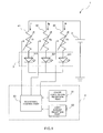
- a light emitting system 1 is, as illustrated in Figs. 1 and 2 , provided with: a power source 2; an LED light emitting device 3 having three types of light emitting parts 31, 32, and 33 that are provided with LED elements 311, 321, 331 to emit red light, green light, and blue light, respectively; variable resistors 41, 42, and 42 that are connected to the LED elements 311, 321, and 331 of the light emitting parts 31, 32, and 33, respectively; and a control device 5.
- the power source 2 supplies a voltage larger than voltage drops of the LED elements 311, 321, and 331.
- the LED light emitting device 3 is provided with the red color based light emitting part 31 that emits the red light, green color based light emitting part 32 that emits the green light, and blue color based light emitting part 33 that emits the blue light, and each of the light emitting parts 31, 32, and 33 includes: the LED element 311, 321, or 331 that emits near-ultraviolet radiation; and resin that is provided to seal the LED element 311, 321, or 331 and dispersed with phosphors that absorb the near-ultraviolet radiation to emit the red light, green light, or blue light.
- the LED light emitting device 3 is, as illustrated in Figs. 2 and 3 , configured such that, on an opening portion bottom surface of a base material 34 that is made of ceramics such as alumina or resin such as polyamide and has a tapered opening portion enlarging outward, of which an inner surface functions as a reflector (reflective plate), the LED elements 311, 321, 331 are surface-mounted (flip-chip mounted); the resin such as heat-curable silicone-based resin dispersed with the phosphors of respective types is filled in the opening portion so as to seal the respective LED elements 311, 321, and 331; and thereby the respective light emitting parts 31, 32, and 33 are formed.
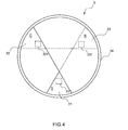
- the LED light emitting device 3 is not necessarily quadrangular-shaped in a plan view as illustrated in Fig. 2 , but may be circular-shaped in a plan view as illustrated in Fig. 4 .
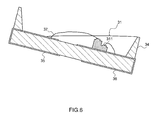
- low partitions (not illustrated) are provided between the respective light emitting parts 31, 32, and 33, and first, as illustrated in Fig. 6 , in a state where the base material 34 is tilted, the resin dispersed with the red phosphors is filled in the opening portion of the base material 34 to form the red color based light emitting part 31 ( Fig. 5 (b) ); then, in the same manner, in the state where the base material 34 is tilted, the resin dispersed with the green phosphors is filed to form the green color based light emitting part 32 ( Fig. 5 (c) ); and finally, the resin dispersed with the blue phosphors is filled to form the blue color based light emitting part 33 ( Fig.
- each of the light emitting parts 31, 32, and 33 partially overlaps with the other light emitting parts, and in the overlapping portion, the red color based light emitting part 31 is positioned below the other light emitting parts, and the blue color based light emitting part 33 is positioned above the other light emitting parts.
- the partitions between the respective light emitting parts 31, 32, and 33 are preferably translucent ones. Also the partitions between the respective light emitting parts 31, 32 and 33 are not necessarily required.
- the base material 34 is provided with an anode 35 and a cathode 35, which are connected to the LED elements 311, 321, and 331 through bonding wires 37.
- the LED elements 311, 321, and 331 of the respective light emitting parts 31, 32, and 33 are all the same ones, each having, for example, a square shape of 350 ⁇ m ⁇ 350 ⁇ m in a plan view, an MQW structure in which six pairs of In 0.03 Ga 0.97 well layer and GaN barrier layer are stacked, and an emission peak wavelength of 380 nm.
- green light phosphors used in the green color based light emitting part 32 for example, ones including YsSiO 5 :Ce,Tb, and (Y,Gd)3Al 5 O 12 :Ce,Tb as main components are cited;
- blue light phosphors used in the blue color based light emitting part 33 for example, ones including BaNgAl 10 O 17 :Eu, Mn as a main component are cited.
- Each of the variable resistors 41, 42, and 43 has three terminals, and is one configured such that a resistance between both end terminals is constant, and by rotating a shaft, resistance values between a central terminal and the both end terminals are varied, on the basis of which amounts of currents Ir, Ig, and Ib flowing through the LED elements 311, 321, and 331 are reversibly adjusted.
- the control device 5 is configured to include a CPU, a memory, and a digital or analog electric circuit having an A/D converter, a D/A converter, and the like, and may be a dedicated one or one configured such that a general-purpose computer such as a personal computer is used for part or all. Alternatively, without using the CPU, the control device 5 may be configured to fulfill functions as respective parts only with the analog circuit, or is not necessarily a physically integrated one but may be one including a plurality of devices that are mutually connected by wired or wireless connections.
- control device 5 is configured to, by storing a predetermined program in the memory and cooperatively operating the CPU and its peripheral devices according to the program, fulfill the functions as a color temperature reception part 51, a light amount reception part 52, and a resistance control part 53.
- the color temperature reception part 51 is one that is provided with, for example, a dial, and receives color temperature data having a color temperature value selected between 1800 and 16000 K by rotating the dial.
- the light amount reception part 52 is one that is provided with, for example, a dial, and receives light amount data having a light amount value (lightness) selected by rotating the dial.
- the resistance control part 53 is one that acquires the color temperature data from the color temperature reception part 51 and the light amount data from the light amount reception part 52; on the basis of the color temperature data and light amount data, generates a control signal; and outputs the control signal to each of the variable resistors 41, 42, and 42 to adjust a resistance value.
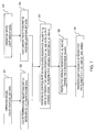
- Step S1 an operator turns the dial to thereby input color temperature data having a predetermined color temperature value (Step S1), and the color temperature data is received by the color temperature reception part 51 (Step S2).
- Step S3 the operator turns the dial to input light amount data having a predetermined light amount value
- Step S4 the light amount data is received by the light amount reception part 52
- the resistance control part 53 acquires the color temperature data and light amount data from the color temperature reception part 51 and the light amount reception part 52, respectively.
- a current ratio among the respective LED elements for achieving a desired color temperature is preliminarily stored in the memory as a table, and on the basis of the color temperature value indicated by the color temperature data, the resistance control part refers to the table to obtain the current ratio among the respective LED elements; also on the basis of the light amount value indicated by the light amount data, calculates a ratio (Ir : Ig : Ib) among values of currents flowing through the respective LED elements 311, 321, and 331 and a total flow amount (Ir + Ig + Ib) of the currents flowing through the respective LED elements 311, 321, and 331; further, from this, calculates resistance values Vr, Vg, and Vb of the respective variable resistors 41, 42, and 43; and generates a control signal having the resistance values to output it to the respective variable resistors 41, 42, and 43 (Step S5).
- the calculation process performed by the resistance control part 53 is extremely simple because the voltage drops of the respective LED elements 311, 321, and 331 are the same, and therefore a calculation circuit of the resistance control part 53 is only required to have an extremely simple configuration.
- the respective variable resistors 41, 42, and 43 receive the control signal to change their resistance values according to the control signal (Step S6).
- Step S7 After the resistance values of the respective variable resistors 41, 42, and 43 have been changed, the values of the currents flowing through the respective LED elements 311, 321, and 331 are varied, and amount values of light emitted by the respective LED elements 311, 321, and 331 are also varied.
- the color temperature and light amount of the white light emitted by the LED light emitting device 3 is controlled.
- the three light emitting parts overlap with one another in their parts within the single LED light emitting device 3, and therefore, from the overlapping portion, light having intermediate color other than the respective single color light of red light, green light, and blue light is emitted, so that even as viewed from an extremely close distance, the white light is easily recognized, and the LED light emitting device 3 can be preferably used as a light source for irradiating a close place.
- the light having the intermediate color other than the single color light is emitted outside the device, and therefore even if, due to a lot-based variation or difference in deterioration rate among the LED elements 311, 321, and 331, an amount of light having any of the colors is changed, an effect of the change is reduced, and the color temperature of the resultant white light is unlikely to be changed. Also, even if the light amounts of the respective light emitting parts 31, 32, and 33 are changed, the color temperature of the white light is not largely changed, and therefore fine color temperature control can be easily performed.
- a color temperature can be controlled with keeping a balance among outputs of the respective LED elements 311, 321, and 331, so that with ensuring predetermined lightness or higher, the fine adjustment of the color temperature of the white light can be made near a black body locus, and even in the case of achieving a color temperature at any of both ends of the black body locus, the lightness is never lowered.
- the LED elements 311, 321, and 331 included in the LED light emitting device 3 are all the same, and therefore the voltage drops are constant, so that it is easy to use the variable resistors 41, 42, and 43 to adjust the values of the currents applied to the corresponding LED elements 311, 321, and 331, and adjust the balance among the light amounts emitted by the respective LED elements 311, 321, and 331, and thereby the color temperature and light amount (lightness) of the white light emitted by the LED light emitting device 3 can be easily controlled.
- An LED light emitting device 3 in the second embodiment is provided with: a red color based light emitting part 31 that contains red phosphors, green phosphors, and blue phosphors at a weight ratio of 70/15/15 and dominantly emits red light; and a blue color based light emitting part 33 that contains red phosphors, green phosphors, and blue phosphors at a weight ratio of 30/25/45 and dominantly emits blue light, and as illustrated in Fig. 9 , the red color based light emitting part 31 and the blue color based light emitting part 33 overlap with each other in their parts. Also, in an overlapping portion, the red color based light emitting part 31 is positioned below the blue color based light emitting part 33.
- the red color based light emitting part 31 and the blue color based light emitting part 33 overlap with each other, the light emitted by the respective light emitting parts 31 and 33 are easily mixed, and therefore natural white light having more intermediate shade can be easily obtained.
- An LED light emitting device 3 in the third embodiment is provided with: a red color based light emitting part 31 that contains red phosphors, green phosphors, and blue phosphors at a weight ratio of 70/15/15 and dominantly emits red light; a green color based light emitting part 32 that contains red phosphors, green phosphors, and blue phosphors at a weight ratio of 30/40/30 and dominantly emits green light; and a blue color based light emitting part 33 that contains red phosphors, green phosphors, and blue phosphors at a weight ratio of 30/25/45 and dominantly emits blue light, and as illustrated in Fig.
- the red color based light emitting part 31, green color based light emitting part 32, and blue color based light emitting part 33 overlap with one another in their parts. Also, in the overlapping portion, the red color based light emitting part 31 is positioned in a lowermost location, and the green color based light emitting part 32 is positioned in an uppermost location.
- the green color based light emitting part 32 an LED element is not sealed, and the green color based light emitting part 32 shares LED elements 311 and 331 with the red color based light emitting part 31 and the blue color based light emitting part 33, respectively. Also, the phosphors contained in the green color based light emitting part 32 are excited by light emitted by the LED element 311 sealed in the red color based light emitting part 31 or the LED element 331 sealed in the blue color based light emitting part 33.
- the green color based light emitting part 32 is positioned in the uppermost location, so that white light in which the red color based light emitted by the red color based light emitting part 31 and the blue color based light emitted by the blue color based light emitting element 33 are mixed is further mixed with the green color based light, and therefore white light having natural shade closer to a black body locus can be emitted.
- the green color based light emitting part 32 an LED element is not sealed, and the green color based light emitting part 32 shares the LED elements 311 and 331 with the red color based light emitting part 31 and the blue color based light emitting part 33, respectively, so that it is not necessary to independently drive three LED elements, and therefore control becomes easy.
- each of the red color based light emitting part 31, the green color based light emitting element 32, and the blue color based light emitting element 33 contains the three types of phosphors; however, as in the first embodiment, the red color based light emitting part 31 may contain only red phosphors; the green color based light emitting part 32 may contain only green phosphors; and the blue color based light emitting part 33 may contain only blue phosphors.
- a dimming control method is not particularly limited, but may be, for example, (1) constant current dimming control by a variable current source, (2) constant voltage dimming control by a variable voltage source and limiting resistor, (3) pulse width dimming control or PWM dimming control using a constant or variable voltage source and a limiting resistor, (4) pulse width dimming control or PWM dimming control using a constant or variable current source and a limiting resistor, or other dimming control.
- locations of the respective light emitting parts 31, 32, and 33 in the LED light emitting device 3 may be those as illustrated in Fig. 12 or 13 .
- color temperature reception part 51 and the light amount reception part 52 may be ones that respectively receive color temperature data and light amount data inputted through input means other than the dials, such as a keyboard.
- a moistureproof layer formed by coating a moistureproof filter or moistureproof paint made of glass or resin may be provided. This enables phosphors, which absorbed moisture, to be prevented from being thermally deteriorated, and a change in color temperature to be suppressed even after lighting for a long time.
- ultraviolet radiation is detrimental to humans, and also results in color fading of an irradiated object, and therefor in order to prevent leakage of ultraviolet radiation that is not absorbed by phosphors, on the surface of each of the light emitting parts 31, 32, and 33, a filter that cuts off light having a wavelength of 410 nm or lower may be provided.
- the LED elements 311, 321, and 331 and respective types of phosphors are not particularly limited in terms of chemical configuration, but may be ones having chemical compositions other than those used in any of the above embodiments.
- the present invention is not limited to any of the above embodiments, but may be configured by appropriately combining parts or all of the above-described various configurations without departing from the scope of the present invention.
- the present invention can be used as a light source for plant growth to, in concert with a biological rhythm or the like of a plant, irradiate white light having a color temperature value corresponding to the rising sun, setting sun, or the like.
Landscapes
- Led Device Packages (AREA)
Abstract
Description
- The present invention relates to an LED light emitting device that can easily control a color temperature of white light.
- Conventionally, there is known an LED light emitting device that uses three types of LED elements, i.e., red, green, and blue LED elements, to emit white light (Patent literature 1). However, the respective LED elements have different forward voltage drops (vf), i.e., the red LED element has a forward voltage drop of approximately 2.0 V, green LED element approximately 3.3 V, and blue LED element approximately 3.4 V, so that, to adjust amounts of currents applied to the respective LED elements to adjust a balance among light amounts, a complicated calculation process is required, and for this reason, there is a problem that controlling a color temperature of the white light is difficult.
- Also, in such a conventional LED light emitting device, red light, green light, and blue light respectively emitted from the LED light emitting device are mixed outside the device to generate the white light, so that even in the case where, from a distance, recognition as the white light can be gained, as viewed from an extremely close distance, the white light is nothing more than being separately recognized as the red light, the green light, and the blue light. For this reason, in order to use such a conventional LED light emitting device as a white light source, a sufficient distance is required from the light source, and therefore the conventional LED light emitting device is inappropriate for a light source for irradiating a close place.
- Such a problem is also recognized even in an LED light emitting device that separately uses red, green, and blue phosphors without combining them to form, in the same device, a red color light emitting part, a green color light emitting part, and a blue color light emitting part that are partitioned from one another.
- Also, in any of the configurations, in the case of, outside a device, mixing respective single color light of red, green, and blue, which were once emitted outside the device, to generate white light, if a light amount of any of the color light is changed, a color temperature of the white light is also largely changed. For this reason, a lot-based variation or difference in deterioration rate among LED elements largely affects the color temperature of the resultant white light, and therefore it is not easy to control it, for example, an extremely fine adjustment or complicated calculation process is required. This means that in an LED light emitting device employing a configuration in which red light, green light, and blue light, which were once emitted outside the device, are mixed to generate white light, even in the case of attempting to finely adjust a color temperature of the white light, the color temperature is likely to be largely changed, and in such a type of LED light emitting device, controlling a color temperature of white light requires a complicated calculation process after all, and is not easy.
- [Patent literature 1]
JPA Heisei 6-151974 - The present invention is made in consideration of such a problem, and has a main object to provide an LED light emitting device that can easily make a fine adjustment of a color temperature of white light. Solution to Problem
- That is, an LED light emitting device according to the present invention is provided with a plurality of types of light emitting parts each having: an LED element that emits ultraviolet radiation or violet color visible light; and a phosphor that absorbs the ultraviolet radiation or the violet color visible light to emit colored light, wherein: lights emitted by the plurality of types of light emitting parts become white light when all mixed with one another; the LED elements of the plurality of types of light emitting parts are all same ones, and mounted on a single base material; and two or more light emitting parts overlap with each other in their parts.
- Note that the ultraviolet radiation refers to electromagnetic radiation having a wavelength of 200 to 400 nm, which includes near-ultraviolet radiation (200 to 380 nm). Also, in the present invention, white light is one type among colored light, and particularly, among the colored light, refers to light that is defined by JIS Z 8725 "Methods for determining distribution temperature and color temperature or correlated color temperature of light sources", and has chromaticity near a black body radiation locus. Note that a chromaticity coordinate of the black body radiation locus is, in the case of being expressed in a uv coordinate (CIE 1960 UCS chromaticity diagram), as in the appendix table 1 of the above standard, and in particular, the white light in the present invention is preferably light having a chromaticity coordinate with a deviation of 0.02 or less in the CIE 1960 UCS chromaticity diagram. This is, in the case of exemplifying the black body radiation locus in an xy coordinate (CIE 1931 chromaticity diagram), light positioned in a range surrounded by, in the appended
figure 1 of the above standard, curves corresponding to duv = 0.02 and duv = -0.02, straight lines corresponding to Tcp^-1 = 0 and Tcp^-1 =640, and spectrum locus. - Further, in the present invention, the number of the light emitting parts and the number of the LED elements may be the same or different, and a plurality of light emitting parts may share one and the same LED element.
- If so, the two or more light emitting parts overlap with each other in their parts in the single LED light emitting device, and thereby from the overlapping portion, light having intermediate color other than the respective single color light of red light, green light, and blue light is emitted, so that even as viewed from an extremely close distance, the white light is easily recognized, and therefore the LED light emitting device can be preferably used as a light source for irradiating a close place.
- Also, according to the LED light emitting device according to the present invention, the plurality of same types of LED elements are used, so that a variation or difference in deterioration rate among the respective LED elements is essentially small, and therefore a color temperature can be easily kept constant both on a production basis and with time. Also, the light having the intermediate color other than the single color light is emitted outside the device, and therefore even if, due to a lot-based variation or difference in deterioration rate occurring among the LED elements, an amount of light having any of the colors is changed, an effect of the change is reduced, and the color temperature of the resultant white light is unlikely to be changed. Also, even if the light amounts of the respective light emitting parts are changed, the color temperature of the white light is not largely changed, and therefore fine color temperature control can be easily performed.
- Further, in the case of using two types of white LED devices having different color temperatures to synthesize white light, fine adjustment of a color temperature can be made; however, in the case of attempting to achieve a color temperature of white light emitted by one of the white LED devices, the other white LED device should be extinguished, and toward any of both ends of a color temperature that can be reproduced by the two types of white LED devices, lightness becomes lower. On the other hand, according to the LED light emitting device according to the present invention, a color temperature can be controlled with keeping a balance among outputs of the respective LED elements, so that with ensuring predetermined lightness or higher, the fine adjustment of the color temperature of the white light can be made near a black body locus, and even in the case of achieving a color temperature at any of both ends of the black body locus, the lightness is never lowered.
- Also, in the present invention, the plurality of light emitting parts are not completely partitioned, so that it is not necessary to form high partitions within the base material, and therefore manufacturing can be achieved at lower cost by a money amount corresponding to the partitions.
- Further, according to the LED light emitting device according to the present invention, the LED elements of the plurality of types of light emitting parts are all the same, and therefore voltage drops are constant, so that, in the case of arranging them in parallel, it is easy to, for example, use variable resistors to adjust values of currents applied to the corresponding LED elements, and adjust a balance among light amounts emitted by the respective LED elements, and thereby the color temperature of the white light emitted by the LED light emitting device can be easily controlled.
- Also, there is known an LED light emitting device configured such that a single LED element is sealed by resin dispersed with a plurality of types of phosphors having different emission colors (typically, red phosphors, green phosphors, and blue phosphors); however, in the LED light emitting device, a color temperature value of white light is determined by mixing amounts of the respective types of phosphors, so that the color temperature value is fixed to a constant temperature value but cannot reversibly adjusted.
- As the LED light emitting device according to the present invention, from the perspective of easily controlling the color temperature of the white light emitted by the LED light emitting device, one provided with at least a red color based light emitting part that dominantly emits red light and a blue color based light emitting part that dominantly emits blue light is preferable, and one further provided with a green color based light emitting part that dominantly emits green light is more preferable. Note that dominantly emitting some colored light means that a maximum peak in a spectrum of the emitted light is only required to be at least positioned in a wavelength region corresponding to the colored light, and may be emitting only the colored light.
- In the LED light emitting device according to the present invention, if partitions are respectively present between the plurality of types of light emitting parts, the respective colored light are unlikely to be mixed. For this reason, the partitions between the respective light emitting parts are configured to be low ones or not provided, and thereby two or more light emitting parts are adapted to overlap with each other in their parts. However, in the LED light emitting device according to the present invention, the ultraviolet radiation emitted from any of the LED elements is once absorbed by the phosphors, so that ensuring lightness is an important subject, and depending on a stacking order of the respective light emitting parts, a loss of a light amount (lightness) in the overlapping portion becomes larger. For this reason, in the part where the two or more light emitting parts overlap with each other, the red color based light emitting part is preferably positioned below the blue color based light emitting part. The blue light is absorbed by the green phosphor and red phosphor to excite them, but the red light is not absorbed by the green phosphor or blue phosphor. On the other hand, the green light is absorbed by the red phosphor to excite it, but not absorbed by the blue phosphor. For this reason, in the case of providing the green color based light emitting part, in the portion where it overlaps with the other light emitting parts, the green color based light emitting part is preferably provided to be positioned above the red color based light emitting part and below the blue color based light emitting part.
- In order to control the color temperature of the white light emitted by the LED light emitting device according to the present invention, it is preferable to use, for example, a light emitting system provided with: the LED light emitting device according to the present invention; output adjustment parts that are respectively connected to the LED elements of the plurality of types of light emitting parts of the LED light emitting device; a single color temperature reception part that receives color temperature data having a predetermined color temperature value; and an output control part that acquires the color temperature data, and outputs a control signal generated on the basis of the color temperature data to the respective output adjustment parts that are respectively connected to the LED elements of the plurality of types of light emitting parts. Such a light emitting system is also included in the present invention.
- A method for manufacturing the LED light emitting device according to the present invention is not particularly limited; however, the LED light emitting device can be manufactured with use of, for example, the following method. That is, a method provided with: a step of mounting a plurality of same LED elements on a bottom surface of a concave portion of a base material having the concave portion that is opened at an upper end surface; a red color based light emitting part forming step of, in a state where the base material mounted with the LED elements is tilted, injecting, in the concave portion of the base material, a resin composition containing a red phosphor to thereby form a red color based light emitting part that seals one of the LED elements with use of the resin composition to dominantly emit red light; and a blue color based light emitting part forming step of, in a state where the base material formed with the red color based light emitting part is tilted, injecting, in the concave portion of the base material, a resin composition containing a blue phosphor so as to overlap with a part of the red color based light emitting part to thereby form a blue color based light emitting part that seals one of the LED elements with use of the resin composition to dominantly emit blue light is cited. Such an LED light emitting device manufacturing method is also included in the present invention.
- The method for manufacturing the LED light emitting device according to the present invention may be further provided with, between the red color based light emitting part forming step and the blue color based light emitting part forming step, a green color based light emitting part forming step of, in the state where the base material formed with the red color based light emitting part is tilted, injecting, in the concave portion of the base material, a resin composition containing a green phosphor so as to overlap a portion of the red color based light emitting part to thereby form a green color based light emitting part that seals one of the LED elements with use of the resin composition to dominantly emit green light. Advantageous Effects of Invention
- According to the present invention having such configurations, even as viewed from an extremely close distance, recognition as white light is easily gained; also fine control of a color temperature is easily performed; and further, with ensuring predetermined lightness or higher, a fine adjustment of the color temperature of the white light can be made near the black body locus.
-
- [
Fig. 1] Fig. 1 is a schematic configuration diagram of a light emitting system according to a first embodiment of the present invention. - [
Fig. 2] Fig. 2 is a plan view of an LED light emitting device in the same embodiment. - [
Fig. 3] Fig. 3 is an AA' line end view of the LED light emitting element in the same embodiment. - [
Fig. 4] Fig. 4 is a plan view of an LED light emitting device in another embodiment. - [
Fig. 5] Fig. 5 is a diagram illustrating a manufacturing method for the LED light emitting device in the same embodiment. - [
Fig. 6] Fig. 6 is a diagram illustrating the manufacturing method for the LED light emitting device in the same embodiment. - [
Fig. 7] Fig. 7 is a flowchart illustrating a method for adjusting a color temperature and light amount of white light emitted by the LED light emitting device in the same embodiment. - [
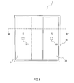
Fig. 8] Fig. 8 is a plan view of an LED light emitting device in a second embodiment. - [
Fig. 9] Fig. 9 is an AA' line end view of the LED light emitting element in the second embodiment. - [
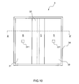
Fig. 10] Fig. 10 is a plan view of an LED light emitting device in a third embodiment. - [
Fig. 11] Fig. 11 is an AA' line end view of the LED light emitting element in the third embodiment. - [
Fig. 12] Fig. 12 is a plan view of an LED light emitting device in still another embodiment. - [
Fig. 13] Fig. 13 is a plan view of an LED light emitting device in yet another embodiment. - Embodiments of the present invention will hereinafter be described referring to the drawings.
- A
light emitting system 1 according to the present embodiment is, as illustrated inFigs. 1 and2 , provided with: apower source 2; an LEDlight emitting device 3 having three types oflight emitting parts LED elements variable resistors LED elements light emitting parts control device 5. - In the following, the respective parts are described in detail.
Thepower source 2 supplies a voltage larger than voltage drops of theLED elements - The LED
light emitting device 3 is provided with the red color basedlight emitting part 31 that emits the red light, green color basedlight emitting part 32 that emits the green light, and blue color basedlight emitting part 33 that emits the blue light, and each of thelight emitting parts LED element LED element - More specifically, the LED
light emitting device 3 is, as illustrated inFigs. 2 and3 , configured such that, on an opening portion bottom surface of abase material 34 that is made of ceramics such as alumina or resin such as polyamide and has a tapered opening portion enlarging outward, of which an inner surface functions as a reflector (reflective plate), theLED elements respective LED elements light emitting parts light emitting device 3 is not necessarily quadrangular-shaped in a plan view as illustrated inFig. 2 , but may be circular-shaped in a plan view as illustrated inFig. 4 . - Next, a method for manufacturing the LED
light emitting device 3 of an embodiment illustrated inFig. 4 is described. To manufacture the LEDlight emitting device 3, as illustrated inFig. 5 , first, on the opening portion bottom surface of thebase material 34, the same three LED elements are mounted (Fig. 5(a) ). - In the present embodiment, between the respective
light emitting parts Fig. 6 , in a state where thebase material 34 is tilted, the resin dispersed with the red phosphors is filled in the opening portion of thebase material 34 to form the red color based light emitting part 31 (Fig. 5 (b) ); then, in the same manner, in the state where thebase material 34 is tilted, the resin dispersed with the green phosphors is filed to form the green color based light emitting part 32 (Fig. 5 (c) ); and finally, the resin dispersed with the blue phosphors is filled to form the blue color based light emitting part 33 (Fig. 5 (d) ). For this reason, as illustrated inFigs. 2 and4 , each of thelight emitting parts light emitting part 31 is positioned below the other light emitting parts, and the blue color basedlight emitting part 33 is positioned above the other light emitting parts. By stacking the respectivelight emitting parts light emitting parts light emitting parts - The
base material 34 is provided with ananode 35 and acathode 35, which are connected to theLED elements bonding wires 37. - The
LED elements light emitting parts - As the red light phosphors used in the red color based
light emitting part 31, for example, ones including Ln2O2S:Eu (Ln = Y, La, Gd, Lu, Sc) as a main component are cited; as the green light phosphors used in the green color basedlight emitting part 32, for example, ones including YsSiO5:Ce,Tb, and (Y,Gd)3Al5O12:Ce,Tb as main components are cited; and as the blue light phosphors used in the blue color basedlight emitting part 33, for example, ones including BaNgAl10O17:Eu, Mn as a main component are cited. - Each of the
variable resistors LED elements - The
control device 5 is configured to include a CPU, a memory, and a digital or analog electric circuit having an A/D converter, a D/A converter, and the like, and may be a dedicated one or one configured such that a general-purpose computer such as a personal computer is used for part or all. Alternatively, without using the CPU, thecontrol device 5 may be configured to fulfill functions as respective parts only with the analog circuit, or is not necessarily a physically integrated one but may be one including a plurality of devices that are mutually connected by wired or wireless connections. Also, thecontrol device 5 is configured to, by storing a predetermined program in the memory and cooperatively operating the CPU and its peripheral devices according to the program, fulfill the functions as a colortemperature reception part 51, a lightamount reception part 52, and aresistance control part 53. - The color
temperature reception part 51 is one that is provided with, for example, a dial, and receives color temperature data having a color temperature value selected between 1800 and 16000 K by rotating the dial. - The light
amount reception part 52 is one that is provided with, for example, a dial, and receives light amount data having a light amount value (lightness) selected by rotating the dial. - The
resistance control part 53 is one that acquires the color temperature data from the colortemperature reception part 51 and the light amount data from the lightamount reception part 52; on the basis of the color temperature data and light amount data, generates a control signal; and outputs the control signal to each of thevariable resistors - Next, a method for using the
light emitting system 1 to adjust a color temperature and a light amount of white light emitted by the LEDlight emitting device 3 is described referring to a flowchart ofFig. 7 . - First, an operator turns the dial to thereby input color temperature data having a predetermined color temperature value (Step S1), and the color temperature data is received by the color temperature reception part 51 (Step S2).
- Similarly, the operator turns the dial to input light amount data having a predetermined light amount value (Step S3), and the light amount data is received by the light amount reception part 52 (Step S4).
- The
resistance control part 53 acquires the color temperature data and light amount data from the colortemperature reception part 51 and the lightamount reception part 52, respectively. On the other hand, a current ratio among the respective LED elements for achieving a desired color temperature is preliminarily stored in the memory as a table, and on the basis of the color temperature value indicated by the color temperature data, the resistance control part refers to the table to obtain the current ratio among the respective LED elements; also on the basis of the light amount value indicated by the light amount data, calculates a ratio (Ir : Ig : Ib) among values of currents flowing through therespective LED elements respective LED elements variable resistors variable resistors - The calculation process performed by the
resistance control part 53 is extremely simple because the voltage drops of therespective LED elements resistance control part 53 is only required to have an extremely simple configuration. - The respective
variable resistors - After the resistance values of the respective
variable resistors respective LED elements respective LED elements - As a result, the color temperature and light amount of the white light emitted by the LED
light emitting device 3 is controlled. - If so, the three light emitting parts overlap with one another in their parts within the single LED
light emitting device 3, and therefore, from the overlapping portion, light having intermediate color other than the respective single color light of red light, green light, and blue light is emitted, so that even as viewed from an extremely close distance, the white light is easily recognized, and the LEDlight emitting device 3 can be preferably used as a light source for irradiating a close place. - Also, according to the LED
light emitting device 3 according to the present embodiment, the light having the intermediate color other than the single color light is emitted outside the device, and therefore even if, due to a lot-based variation or difference in deterioration rate among theLED elements light emitting parts - Further, in the case of using two types of white LED devices having different color temperatures to synthesize white light, a fine adjustment of a color temperature can be made; however, in the case of attempting to achieve a color temperature of white light emitted by one of the white LED devices, the other white LED device should be extinguished, and toward any of both ends of a color temperature that can be reproduced by the two types of white LED devices, lightness becomes lower. On the other hand, according to the LED light emitting device according to the present invention, a color temperature can be controlled with keeping a balance among outputs of the
respective LED elements - Further, according to the LED light emitting device according to the present embodiment, the
LED elements light emitting device 3 are all the same, and therefore the voltage drops are constant, so that it is easy to use thevariable resistors LED elements respective LED elements light emitting device 3 can be easily controlled. - In the following, a second embodiment is described referring to
Figs. 8 and9 ; however, in the following description, the description is provided with focusing on different points from the first embodiment. - An LED
light emitting device 3 in the second embodiment is provided with: a red color basedlight emitting part 31 that contains red phosphors, green phosphors, and blue phosphors at a weight ratio of 70/15/15 and dominantly emits red light; and a blue color basedlight emitting part 33 that contains red phosphors, green phosphors, and blue phosphors at a weight ratio of 30/25/45 and dominantly emits blue light, and as illustrated inFig. 9 , the red color basedlight emitting part 31 and the blue color basedlight emitting part 33 overlap with each other in their parts. Also, in an overlapping portion, the red color basedlight emitting part 31 is positioned below the blue color basedlight emitting part 33. - According to the present embodiment, in the part where the red color based
light emitting part 31 and the blue color basedlight emitting part 33 overlap with each other, the light emitted by the respectivelight emitting parts - In the following, a third embodiment is described referring to
Figs. 10 and11 ; however, in the following description, the description is provided with focusing on different points from the first embodiment. - An LED
light emitting device 3 in the third embodiment is provided with: a red color basedlight emitting part 31 that contains red phosphors, green phosphors, and blue phosphors at a weight ratio of 70/15/15 and dominantly emits red light; a green color basedlight emitting part 32 that contains red phosphors, green phosphors, and blue phosphors at a weight ratio of 30/40/30 and dominantly emits green light; and a blue color basedlight emitting part 33 that contains red phosphors, green phosphors, and blue phosphors at a weight ratio of 30/25/45 and dominantly emits blue light, and as illustrated inFig. 11 , the red color basedlight emitting part 31, green color basedlight emitting part 32, and blue color basedlight emitting part 33 overlap with one another in their parts. Also, in the overlapping portion, the red color basedlight emitting part 31 is positioned in a lowermost location, and the green color basedlight emitting part 32 is positioned in an uppermost location. - In the present embodiment, in the green color based
light emitting part 32, an LED element is not sealed, and the green color basedlight emitting part 32 shares LEDelements light emitting part 31 and the blue color basedlight emitting part 33, respectively. Also, the phosphors contained in the green color basedlight emitting part 32 are excited by light emitted by theLED element 311 sealed in the red color basedlight emitting part 31 or theLED element 331 sealed in the blue color basedlight emitting part 33. - According to the present embodiment as described above, the green color based
light emitting part 32 is positioned in the uppermost location, so that white light in which the red color based light emitted by the red color basedlight emitting part 31 and the blue color based light emitted by the blue color basedlight emitting element 33 are mixed is further mixed with the green color based light, and therefore white light having natural shade closer to a black body locus can be emitted. Also, in the green color basedlight emitting part 32, an LED element is not sealed, and the green color basedlight emitting part 32 shares theLED elements light emitting part 31 and the blue color basedlight emitting part 33, respectively, so that it is not necessary to independently drive three LED elements, and therefore control becomes easy. - In the third embodiment, each of the red color based
light emitting part 31, the green color basedlight emitting element 32, and the blue color basedlight emitting element 33 contains the three types of phosphors; however, as in the first embodiment, the red color basedlight emitting part 31 may contain only red phosphors; the green color basedlight emitting part 32 may contain only green phosphors; and the blue color basedlight emitting part 33 may contain only blue phosphors. - Note that the present invention is not limited to any of the above embodiments.
- For example, a dimming control method is not particularly limited, but may be, for example, (1) constant current dimming control by a variable current source, (2) constant voltage dimming control by a variable voltage source and limiting resistor, (3) pulse width dimming control or PWM dimming control using a constant or variable voltage source and a limiting resistor, (4) pulse width dimming control or PWM dimming control using a constant or variable current source and a limiting resistor, or other dimming control.
- Also, locations of the respective
light emitting parts light emitting device 3 may be those as illustrated inFig. 12 or13 . - Further, the color
temperature reception part 51 and the lightamount reception part 52 may be ones that respectively receive color temperature data and light amount data inputted through input means other than the dials, such as a keyboard. - Also, on a surface of each of the
light emitting parts light emitting device 3, a moistureproof layer formed by coating a moistureproof filter or moistureproof paint made of glass or resin may be provided. This enables phosphors, which absorbed moisture, to be prevented from being thermally deteriorated, and a change in color temperature to be suppressed even after lighting for a long time. - Further, ultraviolet radiation is detrimental to humans, and also results in color fading of an irradiated object, and therefor in order to prevent leakage of ultraviolet radiation that is not absorbed by phosphors, on the surface of each of the
light emitting parts - Also, the
LED elements - Besides, the present invention is not limited to any of the above embodiments, but may be configured by appropriately combining parts or all of the above-described various configurations without departing from the scope of the present invention.
- As described, according to the present invention, the voltage drops in the LED elements of the respective light emitting parts are constant, so that it is easy to adjust the values of the currents applied to the respective LED elements to adjust the balance among the light amounts, and for this reason, the color temperature and light amount (lightness) of the white light emitted by the LED light emitting device can be easily controlled. Accordingly, for example, the present invention can be used as a light source for plant growth to, in concert with a biological rhythm or the like of a plant, irradiate white light having a color temperature value corresponding to the rising sun, setting sun, or the like.
-
- 1:
- Light emitting system
- 3:
- LED light emitting device
- 31, 32, 33:
- Light emitting part
- 311, 321, 331:
- LED element
- 41, 42, 43:
- Variable resistor
- 51:
- Color temperature reception part
- 53:
- Resistance control part
Claims (7)
- An LED light emitting device comprising
a plurality of types of light emitting parts each having: an LED element that emits ultraviolet radiation or violet color visible light; and a phosphor that absorbs the ultraviolet radiation or the violet color visible light to emit colored light, wherein:lights emitted by the plurality of types of light emitting parts become white light when all mixed with each other;the LED elements of the plurality of types of light emitting parts are all same ones, and mounted on a single base material; andtwo or more light emitting parts overlap with each other in their parts. - The LED light emitting device according to claim 1, comprising:at least, a red color based light emitting part that dominantly emits red light; and a blue color based light emitting part that dominantly emits blue light.
- The LED light emitting device according to claim 2, wherein
in the overlapping portion, the red color based light emitting part is positioned below the blue color based light emitting part. - The LED light emitting device according to claim 2, further comprising
a green color based light emitting part that dominantly emits green light, wherein
in the overlapping portion, the green color based light emitting part is positioned above the red color based light emitting part and below the blue color based light emitting part. - A light emitting system comprising:the LED light emitting device according to claim 1;output adjustment parts that are respectively connected to the respective LED elements of the plurality of types of light emitting parts of the LED light emitting device;a single color temperature reception part that receives color temperature data having a predetermined color temperature value; andan output control part that acquires the color temperature data, and outputs a control signal generated on a basis of the color temperature data to the respective output adjustment parts that are respectively connected to the respective LED elements of the plurality of types of light emitting parts.
- An LED light emitting device manufacturing method comprising:a step of mounting a plurality of same LED elements on a bottom surface of a concave portion of a base material having the concave portion that is opened at an upper end surface;a red color based light emitting part forming step of, in a state where the base material mounted with the LED elements is tilted, injecting, in the concave portion of the base material, a resin composition containing a red phosphor to thereby form a red color based light emitting part that seals one of the LED elements with use of the resin composition to dominantly emit red light; anda blue color based light emitting part forming step of, in a state where the base material formed with the red color based light emitting part is tilted, injecting, in the concave portion of the base material, a resin composition containing a blue phosphor so as to overlap with a part of the red color based light emitting part to thereby form a blue color based light emitting part that seals one of the LED elements with use of the resin composition to dominantly emit blue light.
- The LED light emitting device manufacturing method according to claim 6, comprising, between the red color based light emitting part forming step and the blue color based light emitting part forming step, a green color based light emitting part forming step of, in the state where the base material formed with the red color based light emitting part is tilted, injecting, in the concave portion of the base material, a resin composition containing a green phosphor so as to overlap a part of the red color based light emitting part to thereby form a green color based light emitting part that seals one of the LED elements with use of the resin composition to dominantly emit green light.
Applications Claiming Priority (2)
| Application Number | Priority Date | Filing Date | Title |
|---|---|---|---|
| JP2009024884 | 2009-02-05 | ||
| PCT/JP2010/051721 WO2010090289A1 (en) | 2009-02-05 | 2010-02-05 | Led light emitting device |
Publications (3)
| Publication Number | Publication Date |
|---|---|
| EP2395568A1 true EP2395568A1 (en) | 2011-12-14 |
| EP2395568A4 EP2395568A4 (en) | 2012-06-27 |
| EP2395568B1 EP2395568B1 (en) | 2018-04-04 |
Family
ID=42542180
Family Applications (1)
| Application Number | Title | Priority Date | Filing Date |
|---|---|---|---|
| EP10738620.3A Not-in-force EP2395568B1 (en) | 2009-02-05 | 2010-02-05 | Led light emitting device |
Country Status (9)
| Country | Link |
|---|---|
| US (1) | US8704244B2 (en) |
| EP (1) | EP2395568B1 (en) |
| JP (1) | JP4549438B1 (en) |
| KR (1) | KR101670107B1 (en) |
| CN (1) | CN102308398B (en) |
| AU (1) | AU2010211671A1 (en) |
| RU (1) | RU2515185C2 (en) |
| SG (1) | SG173174A1 (en) |
| WO (1) | WO2010090289A1 (en) |
Cited By (1)
| Publication number | Priority date | Publication date | Assignee | Title |
|---|---|---|---|---|
| CN104421711A (en) * | 2013-08-30 | 2015-03-18 | Lg伊诺特有限公司 | Lighting device |
Families Citing this family (20)
| Publication number | Priority date | Publication date | Assignee | Title |
|---|---|---|---|---|
| JP2011523212A (en) * | 2008-06-05 | 2011-08-04 | スリーエム イノベイティブ プロパティズ カンパニー | Light emitting diode with semiconductor wavelength converter bonded |
| JP2013168326A (en) * | 2012-02-16 | 2013-08-29 | Toshiba Lighting & Technology Corp | Lighting device |
| JP2012064925A (en) | 2010-08-18 | 2012-03-29 | Mitsubishi Chemicals Corp | Led light-emitting device and indicator incorporating the same |
| TWI432668B (en) * | 2010-10-11 | 2014-04-01 | Optromax Corp | White light illumination device and method for generating white light |
| DE102011010895B4 (en) * | 2011-02-10 | 2022-04-28 | OSRAM Opto Semiconductors Gesellschaft mit beschränkter Haftung | Light-emitting diode module and method for operating a light-emitting diode module |
| WO2013015058A1 (en) | 2011-07-25 | 2013-01-31 | 日亜化学工業株式会社 | Light-emitting device |
| CN102588805A (en) * | 2012-03-20 | 2012-07-18 | 佛山市国星光电股份有限公司 | Color temperature adjustable LED (light emitting diode) device and color temperature adjustable lamp |
| US9271368B2 (en) | 2012-12-07 | 2016-02-23 | Bridgelux, Inc. | Method and apparatus for providing a passive color control scheme using blue and red emitters |
| CN103458585B (en) * | 2013-09-11 | 2015-07-01 | 北京汽车股份有限公司 | LED soft light bar control module and vehicle |
| JP6203147B2 (en) * | 2014-01-29 | 2017-09-27 | シャープ株式会社 | Light emitting device |
| KR101547480B1 (en) * | 2014-08-20 | 2015-08-26 | 유상우 | Apparatus for driving LED |
| WO2016147484A1 (en) | 2015-03-13 | 2016-09-22 | シャープ株式会社 | Light-emitting device |
| FR3038452A1 (en) * | 2015-06-30 | 2017-01-06 | Commissariat Energie Atomique | SEMICONDUCTOR ELECTROLUMINESCENT DEVICE HAVING A STRUCTURED PHOTOLUMINESCENT LAYER |
| EP3453232A4 (en) * | 2016-05-02 | 2020-07-29 | Growflux Inc. | SYSTEM AND METHOD FOR EXTENDED GARDEN LIGHTING |
| CN109475025B (en) * | 2017-09-08 | 2023-11-07 | 三星电子株式会社 | lighting device |
| CN108463024A (en) * | 2018-02-08 | 2018-08-28 | 深圳万源光引科技有限公司 | Multi-colored led Mixed Lights Illumination method and lighting system |
| US11398458B2 (en) | 2019-12-13 | 2022-07-26 | Lumileds Llc | Multi-color phosphor converted LED package with single cavity |
| WO2021119465A1 (en) * | 2019-12-13 | 2021-06-17 | Lumileds Llc | Leds and multi-color phosphors |
| US11893215B2 (en) | 2021-07-21 | 2024-02-06 | Samsung Electronics Co., Ltd. | Electronic device including flexible display and operation method thereof |
| WO2023075150A1 (en) | 2021-10-28 | 2023-05-04 | 삼성전자주식회사 | Electronic device and control method therefor |
Family Cites Families (27)
| Publication number | Priority date | Publication date | Assignee | Title |
|---|---|---|---|---|
| USRE26251E (en) * | 1961-06-14 | 1967-08-15 | Cathode ray tube having a color- selection electrode with large apertures | |
| US3344301A (en) * | 1966-07-25 | 1967-09-26 | Rauland Corp | Subtractive type color cathode ray tube having overlapping color phosphor areas |
| JPS4889678A (en) * | 1972-02-25 | 1973-11-22 | ||
| JPS48102585A (en) * | 1972-04-04 | 1973-12-22 | ||
| JP2822819B2 (en) | 1992-11-09 | 1998-11-11 | 日亜化学工業株式会社 | Multicolor light emitting device |
| JP3536447B2 (en) | 1995-06-26 | 2004-06-07 | カシオ計算機株式会社 | Color liquid crystal display |
| GB0116991D0 (en) * | 2001-07-12 | 2001-09-05 | Qinetiq Ltd | Novel compounds |
| RU2233013C2 (en) * | 2002-03-06 | 2004-07-20 | Институт проблем химической физики РАН | Semiconductor electroluminescent light source and its manufacturing process (alternatives) |
| WO2003080764A1 (en) * | 2002-03-22 | 2003-10-02 | Nichia Corporation | Nitride phosphor and method for preparation thereof, and light emitting device |
| KR100492938B1 (en) * | 2002-09-11 | 2005-05-30 | 강성진 | A compact-type discharge lamp |
| JP4310093B2 (en) | 2002-10-09 | 2009-08-05 | キヤノン株式会社 | Manufacturing method of solid-state imaging device |
| RU2219622C1 (en) * | 2002-10-25 | 2003-12-20 | Закрытое акционерное общество "Светлана-Оптоэлектроника" | Semiconductor white light source |
| US6919584B2 (en) | 2003-06-19 | 2005-07-19 | Harvatek Corporation | White light source |
| TW200512949A (en) | 2003-09-17 | 2005-04-01 | Nanya Plastics Corp | A method to provide emission of white color light by the principle of secondary excitation and its product |
| US7250715B2 (en) * | 2004-02-23 | 2007-07-31 | Philips Lumileds Lighting Company, Llc | Wavelength converted semiconductor light emitting devices |
| JP2006237217A (en) | 2005-02-24 | 2006-09-07 | Toshiba Discrete Technology Kk | Semiconductor light emitting device and surface light emitting device |
| JP4692059B2 (en) * | 2005-04-25 | 2011-06-01 | パナソニック電工株式会社 | Method for manufacturing light emitting device |
| JP2007049114A (en) * | 2005-05-30 | 2007-02-22 | Sharp Corp | Light emitting device and manufacturing method thereof |
| EP1929532A1 (en) | 2005-09-19 | 2008-06-11 | Koninklijke Philips Electronics N.V. | Variable color light emitting device and method for controlling the same |
| JP4895574B2 (en) | 2005-11-02 | 2012-03-14 | シャープ株式会社 | Wavelength conversion member and light emitting device |
| CN1988188A (en) * | 2005-12-23 | 2007-06-27 | 香港应用科技研究院有限公司 | Light-emitting diode crystal grain with fluorescent layer structure and its manufacturing method |
| US7775687B2 (en) * | 2006-02-20 | 2010-08-17 | Nichia Corporation | Light emitting device |
| JP2008060129A (en) * | 2006-08-29 | 2008-03-13 | Nec Lighting Ltd | Full-color light-emitting diode |
| JP5099418B2 (en) | 2006-11-30 | 2012-12-19 | 東芝ライテック株式会社 | Lighting device |
| DE102007033026A1 (en) * | 2007-07-16 | 2009-01-22 | Osram Gesellschaft mit beschränkter Haftung | Phosphor mixture for a discharge lamp and discharge lamp, in particular Hg low-pressure discharge lamp |
| KR101525274B1 (en) * | 2007-10-26 | 2015-06-02 | 크리, 인코포레이티드 | Illumination device having one or more lumiphors, and methods of fabricating same |
| KR100924912B1 (en) | 2008-07-29 | 2009-11-03 | 서울반도체 주식회사 | Warm white light emitting apparatus and back light module comprising the same |
-
2010
- 2010-02-05 US US13/146,889 patent/US8704244B2/en not_active Expired - Fee Related
- 2010-02-05 SG SG2011054467A patent/SG173174A1/en unknown
- 2010-02-05 EP EP10738620.3A patent/EP2395568B1/en not_active Not-in-force
- 2010-02-05 WO PCT/JP2010/051721 patent/WO2010090289A1/en not_active Ceased
- 2010-02-05 KR KR1020117019802A patent/KR101670107B1/en not_active Expired - Fee Related
- 2010-02-05 RU RU2011136713/28A patent/RU2515185C2/en not_active IP Right Cessation
- 2010-02-05 AU AU2010211671A patent/AU2010211671A1/en not_active Abandoned
- 2010-02-05 CN CN201080006776.4A patent/CN102308398B/en not_active Expired - Fee Related
- 2010-02-05 JP JP2010515303A patent/JP4549438B1/en not_active Expired - Fee Related
Cited By (2)
| Publication number | Priority date | Publication date | Assignee | Title |
|---|---|---|---|---|
| CN104421711A (en) * | 2013-08-30 | 2015-03-18 | Lg伊诺特有限公司 | Lighting device |
| CN104421711B (en) * | 2013-08-30 | 2019-07-12 | Lg伊诺特有限公司 | Lighting device |
Also Published As
| Publication number | Publication date |
|---|---|
| CN102308398A (en) | 2012-01-04 |
| CN102308398B (en) | 2015-03-25 |
| JP4549438B1 (en) | 2010-09-22 |
| KR20110120915A (en) | 2011-11-04 |
| EP2395568A4 (en) | 2012-06-27 |
| EP2395568B1 (en) | 2018-04-04 |
| AU2010211671A1 (en) | 2011-09-01 |
| RU2011136713A (en) | 2013-03-10 |
| RU2515185C2 (en) | 2014-05-10 |
| KR101670107B1 (en) | 2016-11-09 |
| US20110278606A1 (en) | 2011-11-17 |
| HK1165906A1 (en) | 2012-10-12 |
| US8704244B2 (en) | 2014-04-22 |
| WO2010090289A1 (en) | 2010-08-12 |
| SG173174A1 (en) | 2011-08-29 |
| JPWO2010090289A1 (en) | 2012-08-09 |
Similar Documents
| Publication | Publication Date | Title |
|---|---|---|
| EP2395568B1 (en) | Led light emitting device | |
| US8174189B2 (en) | White LED device capable of adjusting correlated color temperature | |
| JP5005712B2 (en) | Light emitting device | |
| US7646032B2 (en) | White light LED devices with flat spectra | |
| EP3845033B1 (en) | Cyan enriched white light | |
| US7531956B2 (en) | Light emitting device and phosphor for the same | |
| JP5042999B2 (en) | Lighting system with luminescent material to compensate for color shortage | |
| US20130141013A1 (en) | Light emission apparatus, illumination system and illumination method | |
| US20140340890A1 (en) | Light emitting apparatus and method for manufacturing same | |
| KR20010089508A (en) | Tri-color, white light led lamps | |
| KR20170134241A (en) | Light emitting device | |
| JP2012113958A (en) | Light-emitting device | |
| US11145793B2 (en) | Light emitting diode with high melanopic spectral content | |
| JP2012191225A (en) | Light-emitting device | |
| US20160223147A1 (en) | Light emitting device | |
| CN217235328U (en) | Light source module, lighting system and lamp | |
| US20060290275A1 (en) | Light emitting device and phosphor for the same | |
| HK1165906B (en) | Led light emitting device | |
| JP2017522412A (en) | Phosphor composition and lighting fixture comprising the same | |
| CN119695043A (en) | A multi-spectrum white light LED device and dimming method |
Legal Events
| Date | Code | Title | Description |
|---|---|---|---|
| PUAI | Public reference made under article 153(3) epc to a published international application that has entered the european phase |
Free format text: ORIGINAL CODE: 0009012 |
|
| 17P | Request for examination filed |
Effective date: 20110729 |
|
| AK | Designated contracting states |
Kind code of ref document: A1 Designated state(s): AT BE BG CH CY CZ DE DK EE ES FI FR GB GR HR HU IE IS IT LI LT LU LV MC MK MT NL NO PL PT RO SE SI SK SM TR |
|
| DAX | Request for extension of the european patent (deleted) | ||
| A4 | Supplementary search report drawn up and despatched |
Effective date: 20120524 |
|
| RIC1 | Information provided on ipc code assigned before grant |
Ipc: H01L 33/00 20100101ALI20120518BHEP Ipc: H01L 25/075 20060101ALI20120518BHEP Ipc: H01L 33/50 20100101AFI20120518BHEP |
|
| RAP1 | Party data changed (applicant data changed or rights of an application transferred) |
Owner name: CCS INC. Owner name: MITSUBISHI CHEMICAL CORPORATION |
|
| RAP1 | Party data changed (applicant data changed or rights of an application transferred) |
Owner name: CCS INC. |
|
| 17Q | First examination report despatched |
Effective date: 20160217 |
|
| GRAP | Despatch of communication of intention to grant a patent |
Free format text: ORIGINAL CODE: EPIDOSNIGR1 |
|
| STAA | Information on the status of an ep patent application or granted ep patent |
Free format text: STATUS: GRANT OF PATENT IS INTENDED |
|
| RIC1 | Information provided on ipc code assigned before grant |
Ipc: H05B 33/08 20060101ALN20170511BHEP Ipc: H01L 33/50 20100101AFI20170511BHEP Ipc: H01L 25/075 20060101ALI20170511BHEP |
|
| INTG | Intention to grant announced |
Effective date: 20170523 |
|
| GRAJ | Information related to disapproval of communication of intention to grant by the applicant or resumption of examination proceedings by the epo deleted |
Free format text: ORIGINAL CODE: EPIDOSDIGR1 |
|
| STAA | Information on the status of an ep patent application or granted ep patent |
Free format text: STATUS: EXAMINATION IS IN PROGRESS |
|
| INTC | Intention to grant announced (deleted) | ||
| GRAP | Despatch of communication of intention to grant a patent |
Free format text: ORIGINAL CODE: EPIDOSNIGR1 |
|
| STAA | Information on the status of an ep patent application or granted ep patent |
Free format text: STATUS: GRANT OF PATENT IS INTENDED |
|
| RIC1 | Information provided on ipc code assigned before grant |
Ipc: H05B 33/08 20060101ALN20171017BHEP Ipc: H01L 25/075 20060101ALI20171017BHEP Ipc: H01L 33/50 20100101AFI20171017BHEP |
|
| INTG | Intention to grant announced |
Effective date: 20171116 |
|
| GRAS | Grant fee paid |
Free format text: ORIGINAL CODE: EPIDOSNIGR3 |
|
| GRAA | (expected) grant |
Free format text: ORIGINAL CODE: 0009210 |
|
| STAA | Information on the status of an ep patent application or granted ep patent |
Free format text: STATUS: THE PATENT HAS BEEN GRANTED |
|
| AK | Designated contracting states |
Kind code of ref document: B1 Designated state(s): AT BE BG CH CY CZ DE DK EE ES FI FR GB GR HR HU IE IS IT LI LT LU LV MC MK MT NL NO PL PT RO SE SI SK SM TR |
|
| REG | Reference to a national code |
Ref country code: GB Ref legal event code: FG4D |
|
| REG | Reference to a national code |
Ref country code: CH Ref legal event code: EP |
|
| REG | Reference to a national code |
Ref country code: AT Ref legal event code: REF Ref document number: 986491 Country of ref document: AT Kind code of ref document: T Effective date: 20180415 |
|
| REG | Reference to a national code |
Ref country code: NL Ref legal event code: FP |
|
| REG | Reference to a national code |
Ref country code: IE Ref legal event code: FG4D |
|
| REG | Reference to a national code |
Ref country code: DE Ref legal event code: R096 Ref document number: 602010049661 Country of ref document: DE |
|
| REG | Reference to a national code |
Ref country code: LT Ref legal event code: MG4D |
|
| PG25 | Lapsed in a contracting state [announced via postgrant information from national office to epo] |
Ref country code: NO Free format text: LAPSE BECAUSE OF FAILURE TO SUBMIT A TRANSLATION OF THE DESCRIPTION OR TO PAY THE FEE WITHIN THE PRESCRIBED TIME-LIMIT Effective date: 20180704 Ref country code: FI Free format text: LAPSE BECAUSE OF FAILURE TO SUBMIT A TRANSLATION OF THE DESCRIPTION OR TO PAY THE FEE WITHIN THE PRESCRIBED TIME-LIMIT Effective date: 20180404 Ref country code: LT Free format text: LAPSE BECAUSE OF FAILURE TO SUBMIT A TRANSLATION OF THE DESCRIPTION OR TO PAY THE FEE WITHIN THE PRESCRIBED TIME-LIMIT Effective date: 20180404 Ref country code: PL Free format text: LAPSE BECAUSE OF FAILURE TO SUBMIT A TRANSLATION OF THE DESCRIPTION OR TO PAY THE FEE WITHIN THE PRESCRIBED TIME-LIMIT Effective date: 20180404 Ref country code: ES Free format text: LAPSE BECAUSE OF FAILURE TO SUBMIT A TRANSLATION OF THE DESCRIPTION OR TO PAY THE FEE WITHIN THE PRESCRIBED TIME-LIMIT Effective date: 20180404 Ref country code: SE Free format text: LAPSE BECAUSE OF FAILURE TO SUBMIT A TRANSLATION OF THE DESCRIPTION OR TO PAY THE FEE WITHIN THE PRESCRIBED TIME-LIMIT Effective date: 20180404 Ref country code: BG Free format text: LAPSE BECAUSE OF FAILURE TO SUBMIT A TRANSLATION OF THE DESCRIPTION OR TO PAY THE FEE WITHIN THE PRESCRIBED TIME-LIMIT Effective date: 20180704 |
|
| PG25 | Lapsed in a contracting state [announced via postgrant information from national office to epo] |
Ref country code: LV Free format text: LAPSE BECAUSE OF FAILURE TO SUBMIT A TRANSLATION OF THE DESCRIPTION OR TO PAY THE FEE WITHIN THE PRESCRIBED TIME-LIMIT Effective date: 20180404 Ref country code: GR Free format text: LAPSE BECAUSE OF FAILURE TO SUBMIT A TRANSLATION OF THE DESCRIPTION OR TO PAY THE FEE WITHIN THE PRESCRIBED TIME-LIMIT Effective date: 20180705 Ref country code: HR Free format text: LAPSE BECAUSE OF FAILURE TO SUBMIT A TRANSLATION OF THE DESCRIPTION OR TO PAY THE FEE WITHIN THE PRESCRIBED TIME-LIMIT Effective date: 20180404 |
|
| REG | Reference to a national code |
Ref country code: AT Ref legal event code: MK05 Ref document number: 986491 Country of ref document: AT Kind code of ref document: T Effective date: 20180404 |
|
| PG25 | Lapsed in a contracting state [announced via postgrant information from national office to epo] |
Ref country code: PT Free format text: LAPSE BECAUSE OF FAILURE TO SUBMIT A TRANSLATION OF THE DESCRIPTION OR TO PAY THE FEE WITHIN THE PRESCRIBED TIME-LIMIT Effective date: 20180806 |
|
| REG | Reference to a national code |
Ref country code: DE Ref legal event code: R097 Ref document number: 602010049661 Country of ref document: DE |
|
| PG25 | Lapsed in a contracting state [announced via postgrant information from national office to epo] |
Ref country code: DK Free format text: LAPSE BECAUSE OF FAILURE TO SUBMIT A TRANSLATION OF THE DESCRIPTION OR TO PAY THE FEE WITHIN THE PRESCRIBED TIME-LIMIT Effective date: 20180404 Ref country code: AT Free format text: LAPSE BECAUSE OF FAILURE TO SUBMIT A TRANSLATION OF THE DESCRIPTION OR TO PAY THE FEE WITHIN THE PRESCRIBED TIME-LIMIT Effective date: 20180404 Ref country code: EE Free format text: LAPSE BECAUSE OF FAILURE TO SUBMIT A TRANSLATION OF THE DESCRIPTION OR TO PAY THE FEE WITHIN THE PRESCRIBED TIME-LIMIT Effective date: 20180404 Ref country code: SK Free format text: LAPSE BECAUSE OF FAILURE TO SUBMIT A TRANSLATION OF THE DESCRIPTION OR TO PAY THE FEE WITHIN THE PRESCRIBED TIME-LIMIT Effective date: 20180404 Ref country code: RO Free format text: LAPSE BECAUSE OF FAILURE TO SUBMIT A TRANSLATION OF THE DESCRIPTION OR TO PAY THE FEE WITHIN THE PRESCRIBED TIME-LIMIT Effective date: 20180404 Ref country code: CZ Free format text: LAPSE BECAUSE OF FAILURE TO SUBMIT A TRANSLATION OF THE DESCRIPTION OR TO PAY THE FEE WITHIN THE PRESCRIBED TIME-LIMIT Effective date: 20180404 |
|
| PLBE | No opposition filed within time limit |
Free format text: ORIGINAL CODE: 0009261 |
|
| STAA | Information on the status of an ep patent application or granted ep patent |
Free format text: STATUS: NO OPPOSITION FILED WITHIN TIME LIMIT |
|
| PG25 | Lapsed in a contracting state [announced via postgrant information from national office to epo] |
Ref country code: IT Free format text: LAPSE BECAUSE OF FAILURE TO SUBMIT A TRANSLATION OF THE DESCRIPTION OR TO PAY THE FEE WITHIN THE PRESCRIBED TIME-LIMIT Effective date: 20180404 Ref country code: SM Free format text: LAPSE BECAUSE OF FAILURE TO SUBMIT A TRANSLATION OF THE DESCRIPTION OR TO PAY THE FEE WITHIN THE PRESCRIBED TIME-LIMIT Effective date: 20180404 |
|
| 26N | No opposition filed |
Effective date: 20190107 |
|
| PG25 | Lapsed in a contracting state [announced via postgrant information from national office to epo] |
Ref country code: SI Free format text: LAPSE BECAUSE OF FAILURE TO SUBMIT A TRANSLATION OF THE DESCRIPTION OR TO PAY THE FEE WITHIN THE PRESCRIBED TIME-LIMIT Effective date: 20180404 |
|
| REG | Reference to a national code |
Ref country code: CH Ref legal event code: PL |
|
| GBPC | Gb: european patent ceased through non-payment of renewal fee |
Effective date: 20190205 |
|
| PG25 | Lapsed in a contracting state [announced via postgrant information from national office to epo] |
Ref country code: LU Free format text: LAPSE BECAUSE OF NON-PAYMENT OF DUE FEES Effective date: 20190205 Ref country code: MC Free format text: LAPSE BECAUSE OF FAILURE TO SUBMIT A TRANSLATION OF THE DESCRIPTION OR TO PAY THE FEE WITHIN THE PRESCRIBED TIME-LIMIT Effective date: 20180404 |
|
| REG | Reference to a national code |
Ref country code: BE Ref legal event code: MM Effective date: 20190228 |
|
| REG | Reference to a national code |
Ref country code: IE Ref legal event code: MM4A |
|
| PG25 | Lapsed in a contracting state [announced via postgrant information from national office to epo] |
Ref country code: LI Free format text: LAPSE BECAUSE OF NON-PAYMENT OF DUE FEES Effective date: 20190228 Ref country code: CH Free format text: LAPSE BECAUSE OF NON-PAYMENT OF DUE FEES Effective date: 20190228 |
|
| PG25 | Lapsed in a contracting state [announced via postgrant information from national office to epo] |
Ref country code: GB Free format text: LAPSE BECAUSE OF NON-PAYMENT OF DUE FEES Effective date: 20190205 Ref country code: IE Free format text: LAPSE BECAUSE OF NON-PAYMENT OF DUE FEES Effective date: 20190205 |
|
| PG25 | Lapsed in a contracting state [announced via postgrant information from national office to epo] |
Ref country code: BE Free format text: LAPSE BECAUSE OF NON-PAYMENT OF DUE FEES Effective date: 20190228 Ref country code: FR Free format text: LAPSE BECAUSE OF NON-PAYMENT OF DUE FEES Effective date: 20190228 |
|
| PG25 | Lapsed in a contracting state [announced via postgrant information from national office to epo] |
Ref country code: TR Free format text: LAPSE BECAUSE OF FAILURE TO SUBMIT A TRANSLATION OF THE DESCRIPTION OR TO PAY THE FEE WITHIN THE PRESCRIBED TIME-LIMIT Effective date: 20180404 |
|
| PGFP | Annual fee paid to national office [announced via postgrant information from national office to epo] |
Ref country code: DE Payment date: 20200226 Year of fee payment: 11 Ref country code: NL Payment date: 20200220 Year of fee payment: 11 |
|
| PG25 | Lapsed in a contracting state [announced via postgrant information from national office to epo] |
Ref country code: MT Free format text: LAPSE BECAUSE OF NON-PAYMENT OF DUE FEES Effective date: 20190205 |
|
| PG25 | Lapsed in a contracting state [announced via postgrant information from national office to epo] |
Ref country code: CY Free format text: LAPSE BECAUSE OF FAILURE TO SUBMIT A TRANSLATION OF THE DESCRIPTION OR TO PAY THE FEE WITHIN THE PRESCRIBED TIME-LIMIT Effective date: 20180404 |
|
| PG25 | Lapsed in a contracting state [announced via postgrant information from national office to epo] |
Ref country code: IS Free format text: LAPSE BECAUSE OF FAILURE TO SUBMIT A TRANSLATION OF THE DESCRIPTION OR TO PAY THE FEE WITHIN THE PRESCRIBED TIME-LIMIT Effective date: 20180804 |
|
| PG25 | Lapsed in a contracting state [announced via postgrant information from national office to epo] |
Ref country code: HU Free format text: LAPSE BECAUSE OF FAILURE TO SUBMIT A TRANSLATION OF THE DESCRIPTION OR TO PAY THE FEE WITHIN THE PRESCRIBED TIME-LIMIT; INVALID AB INITIO Effective date: 20100205 |
|
| REG | Reference to a national code |
Ref country code: DE Ref legal event code: R119 Ref document number: 602010049661 Country of ref document: DE |
|
| REG | Reference to a national code |
Ref country code: NL Ref legal event code: MM Effective date: 20210301 |
|
| PG25 | Lapsed in a contracting state [announced via postgrant information from national office to epo] |
Ref country code: NL Free format text: LAPSE BECAUSE OF NON-PAYMENT OF DUE FEES Effective date: 20210301 |
|
| PG25 | Lapsed in a contracting state [announced via postgrant information from national office to epo] |
Ref country code: DE Free format text: LAPSE BECAUSE OF NON-PAYMENT OF DUE FEES Effective date: 20210901 |
|
| PG25 | Lapsed in a contracting state [announced via postgrant information from national office to epo] |
Ref country code: MK Free format text: LAPSE BECAUSE OF FAILURE TO SUBMIT A TRANSLATION OF THE DESCRIPTION OR TO PAY THE FEE WITHIN THE PRESCRIBED TIME-LIMIT Effective date: 20180404 |