EP2394800B1 - Device for gripping and lifting objects - Google Patents
Device for gripping and lifting objects Download PDFInfo
- Publication number
- EP2394800B1 EP2394800B1 EP10165608A EP10165608A EP2394800B1 EP 2394800 B1 EP2394800 B1 EP 2394800B1 EP 10165608 A EP10165608 A EP 10165608A EP 10165608 A EP10165608 A EP 10165608A EP 2394800 B1 EP2394800 B1 EP 2394800B1
- Authority
- EP
- European Patent Office
- Prior art keywords
- accordance
- threaded spindle
- threaded
- guide slide
- toggle lever
- Prior art date
- Legal status (The legal status is an assumption and is not a legal conclusion. Google has not performed a legal analysis and makes no representation as to the accuracy of the status listed.)
- Active
Links
Images


Classifications
-
- B—PERFORMING OPERATIONS; TRANSPORTING
- B25—HAND TOOLS; PORTABLE POWER-DRIVEN TOOLS; MANIPULATORS
- B25J—MANIPULATORS; CHAMBERS PROVIDED WITH MANIPULATION DEVICES
- B25J15/00—Gripping heads and other end effectors
- B25J15/02—Gripping heads and other end effectors servo-actuated
- B25J15/0253—Gripping heads and other end effectors servo-actuated comprising parallel grippers
- B25J15/0266—Gripping heads and other end effectors servo-actuated comprising parallel grippers actuated by articulated links
- B25J15/0273—Gripping heads and other end effectors servo-actuated comprising parallel grippers actuated by articulated links comprising linear guide means
-
- B—PERFORMING OPERATIONS; TRANSPORTING
- B25—HAND TOOLS; PORTABLE POWER-DRIVEN TOOLS; MANIPULATORS
- B25J—MANIPULATORS; CHAMBERS PROVIDED WITH MANIPULATION DEVICES
- B25J15/00—Gripping heads and other end effectors
- B25J15/02—Gripping heads and other end effectors servo-actuated
- B25J15/0253—Gripping heads and other end effectors servo-actuated comprising parallel grippers
- B25J15/026—Gripping heads and other end effectors servo-actuated comprising parallel grippers actuated by gears
-
- B—PERFORMING OPERATIONS; TRANSPORTING
- B65—CONVEYING; PACKING; STORING; HANDLING THIN OR FILAMENTARY MATERIAL
- B65G—TRANSPORT OR STORAGE DEVICES, e.g. CONVEYORS FOR LOADING OR TIPPING, SHOP CONVEYOR SYSTEMS OR PNEUMATIC TUBE CONVEYORS
- B65G47/00—Article or material-handling devices associated with conveyors; Methods employing such devices
- B65G47/74—Feeding, transfer, or discharging devices of particular kinds or types
- B65G47/90—Devices for picking-up and depositing articles or materials
-
- B—PERFORMING OPERATIONS; TRANSPORTING
- B65—CONVEYING; PACKING; STORING; HANDLING THIN OR FILAMENTARY MATERIAL
- B65B—MACHINES, APPARATUS OR DEVICES FOR, OR METHODS OF, PACKAGING ARTICLES OR MATERIALS; UNPACKING
- B65B35/00—Supplying, feeding, arranging or orientating articles to be packaged
- B65B35/10—Feeding, e.g. conveying, single articles
- B65B35/16—Feeding, e.g. conveying, single articles by grippers
Definitions
- the invention relates to a device for gripping and lifting objects, consisting of at least two gripping arms supported on a support frame, between which the male object can be clamped, and from a driving drive device drivingly connected to the respective gripper arm via intermediate links.
- the device has become known consists of two in the initial state parallel and spaced apart gripping arms, which are connected via a drive linkage with a drive device.
- the drive linkage is pressed apart, so that the gripping arms can be moved around the point of application of the drive linkage scissors-shaped and to clamp the load by means of friction and absorb.
- the tension forces are often insufficient to reliably hold these objects between the gripping arms; an increase in force is not possible due to the drive device used and the existing geometry.
- the gripping device in particular the gripping arms to replace, because the gripping arms of the known gripping and handling devices can be regulated only insignificantly in their width.
- the respective intermediate member is designed as an L-shaped guide carriage, that the first free end of the guide carriage is drivingly connected by means of a toggle lever with the drive means, that the second free end of the guide carriage with the respective gripping arm, opposite the point of application of the toggle lever on the guide carriage is directly or via intermediate links in frictional operative connection, and that the guide carriage and the respective gripper arm are held linearly displaceable on a guide linkage.
- the guide carriage is assigned in each case a threaded spindle, the mutually opposite thread directions have that the respective guide carriage is non-positively connected to the respective threaded spindle, and that on the external thread of the threaded spindle, a jaw is screwed, which is connected to the respective gripping arm and which is rotatably and axially displaceably held on the guide rod, it is achieved that the Distance between the gripping arms on the rotation of the respective threaded spindle without time delay and without replacement of the gripping arms is variably adjustable.
- the constant force applied by the drive device can be variably transferred in a predetermined force transmission ratio to the guide carriage and thus to the gripping arms.
- the toggle lever is acted upon by the drive unit with a constant force, so that the pivot point of the toggle lever, which is connected to the drive unit, covers a stroke and thereby spreads the rods of the toggle lever, by which a clamping force is transmitted to the gripping arms.
- the toggle lever in this case has a power transmission, which has starting from the starting point of the toggle lever, ie in the nearly closed state up to a position spread almost 180 ° a linearly increasing force curve. This linear force curve is transmitted from the gripping arms to the object.
- the gripping arms are directly aligned with the size relationships of the object to be picked up, and the toggle lever is positioned, for example, in an angular spread position of 165 °.
- the distance to be covered of the toggle lever is then relatively low, so that a maximum clamping force is exerted by the toggle lever on the object.
- the toggle lever force can be changed so that it starts from the starting position, ie from a spread angle of about 10 ° and the stroke is limited.
- the limitation of the stroke can be done for example by means of a threaded pin and set variably.
- the clamping force applied by the gripping arms which acts on the object to be picked up, can be adapted exactly to the conditions of the object. Accordingly, if the object is extremely light and fragile, the force of the drive means is reduced by the attitude angle of the toggle such that the tension force acting on the object does not destroy it and nevertheless reliably fix it.
- a change in the lever ratios of the toggle lever can be achieved, in particular, in that the points of application of force between the drive device of the respective gripper arms are displaceable on the guide carriage so that they can be adjusted variably relative to the desired power transmission ratio.
- toggle lever Another advantage of the toggle lever is the fact that the toggle also affects the speeds of the gripping arms, in such a way that the gripping arms have a higher movement speed in a wide spread position, as if the position of the toggle lever is almost closed.
- the toggle lever thus has a very favorable kinematics, which allows a fast opening and closing of the gripper arms.
- the clamping force acting on the objects can be set exactly, so that the objects, even if they are elastically deformable, defined can be clamped or if the objects have a very high Have self-weight, a reliable and sufficient clamping force acts on the objects.
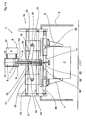
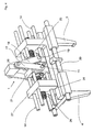
- FIG. 1 a device 1 for gripping and lifting objects 2 is shown, which is supported on a support frame 3 on a floor 40.
- the articles 2 are to be lifted from the ground 40 and transported to another position.
- two mutually spaced gripping arms 4, 5 are provided, between which the male object 2 is held by a clamping force in the operating state.
- the gripper arms 4, 5 are held linearly displaceable on a guide rod 14.
- a possible alternative of the drive device 6 comprises a pump P, are pressed by the hydraulic fluid via leads 10 into two pressure chambers 9 alternately.
- the pressure chambers 9 are surrounded by a housing 11 and separated from each other by a piston 7; the two lines 10 open into the pressure chambers 9.
- the hydraulic fluid moves the piston 7 in response to the respective filling of the pressure chamber 9.
- Already the pressure surface occupied by the piston 7 reduces or increases the force provided by the pump P available.
- a piston rod 8 is mounted, which protrudes from the housing 11. Is thus the upper pressure chamber 9 in the initial state shown the FIG. 1 a filled with hydraulic fluid through the pump P, the piston 7 moves down, so that the piston rod 8, which is connected to a point 16 on a toggle lever 15, is pushed down.
- the point 16 is in the support frame 3 held axially displaceable in a linear guide, so that it is delivered by the piston rod 8 in the direction of the gripping arms 4, 5.
- the guide carriage 21 is designed in its cross-section L-shaped.
- the first free end 22 of the guide carriage 21 is assigned to the respective rod 17 or 18 of the bell crank 15; the rod 17 or 18 is pivotally connected to the guide carriage 21.
- the second free end 23 of the guide carriage 21 with the respective gripping arms 4 or 5 is, opposite the point 16 of the toggle lever 15 on the guide carriage 21, directly or via intermediate members 24, 25 or 27 in non-positive operative connection.
- the intermediate member 13 is thus formed by the piston 7, the piston rod 8, the toggle lever 15 and the guide carriage 21 in this particular embodiment.
- the guide carriage 21 has a total of four passage openings, which are designed round in their cross-section. In the respective passage opening a rod 20 is inserted, through which the guide rod 14 is formed. Consequently, each of the two guide carriages 21, preferably in the corner regions, is supported so as to be axially displaceable on the four rods 20 of the guide linkage 14. As a result of the spreading movement of the toggle lever 15, each of the two guide carriages 21 is thus pressed outward.
- the L-shaped designed carriage 21 is connected to the point 19 frictionally with one of the gripping arms 4 and 5. Of the Attack point 19 is therefore on the opposite side of the respective point of attack 16.
- the toggle 15 serves not only as an intermediate member 13 for transmitting power provided by the driving device 6, but also for translating the constant driving force of the driving device 6 and the piston 7.
- the transmission ratio of the toggle lever 15 depends essentially on its geometric configurations.
- the points of application 16 and 19 between the piston rod 8 and the respective guide carriage 21 are therefore variably adjustable, so that the force transmission ratio of the toggle lever 15 to the conditions of the objects 2 to be accommodated without further replacement or retrofitting measures are adaptable.
- FIG. 1b It is shown that the gripping arms 4 and 5 clamp the object 2 and lift it from the bottom 40.
- the article 2 can be transported, for example, along a rail guide or the like.
- the toggle 15 is completely spread apart.
- FIGS. 2a and 2 B can the non-positive operative connection between the guide carriage 21 and the respective gripping arm 4 or 5 be removed.
- a groove is incorporated, in which a wedge-shaped projection, which is integrally formed on the guide carriage 21, is inserted.
- the L-shaped cross-sectional shape of the guide carriage 21 are the two FIGS. 2a and 2 B refer to.
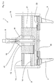
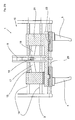
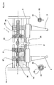
- FIGS. 3a . 3b and 4 a device 1 'for lifting and gripping objects 2 is shown, in addition to those in the FIGS. 1a to 2b has two threaded spindles 24 and 25 described components.
- the outer contour of the threaded spindle 24 is designed as a right-handed and the outer contour of the threaded spindle 25 as a left-handed thread; Thus, the directions of rotation of the threads of the two threaded spindles 24 and 25 are opposite to each other.
- the threaded spindles 24, 25 are also held between the rods 20 of the guide rod 14 and spaced from each other.
- the threaded spindles 24, 25 are designed as hollow bodies, which are arranged in alignment with each other, so that in the interior of the respective threaded spindle 24, 25, a drive shaft 31 is used.
- the drive shaft 31 is rotated for example by means of a V-belt drive by a motor 29 in rotation.
- the introduction of force is essentially aligned with the linear movement of the piston rod 8, so that the available space is used for the initiation of the forces.
- the two guide carriages 21 enclose the threaded spindle 24 or 25 and are connected thereto via a roller bearing 29 designed as a roller bearing, so that a relative movement can take place between the guide slide 21 arranged in a rotationally fixed manner and the rotating threaded spindle 24 or 25.
- the rolling bearings 29 also serve as force transmission elements, because the expended by the toggle 15 spreading force is transmitted through the roller bearings 29 of the guide carriage 21 to the respective threaded spindle 24 or 25.
- the threaded spindle 24 and 25 rotatably connected to the drive shaft 31 and axially displaceably connected.
- the threaded spindle 24 and 25 may be axially displaced along the drive shaft 31;
- the rotational forces transmitted by the drive shaft 31 are transmitted, for example, by means of a square profile or by means of a wedge-groove connection.
- the drive shaft 31 is thus positively connected to the respective threaded spindle 24 and 25 respectively.
- the two gripping arms 4 and 5 are moved outwards or inwards depending on the direction of rotation, so that the distance between the two gripping arms 4 and 5 is variable by the drive shaft 31 and the threaded spindles 24 and 25 is adjustable.
- the position of the guide carriage 21 does not change.
Description
Die Erfindung bezieht sich auf eine Vorrichtung zum Greifen und Anheben von Gegenständen, bestehend aus mindestens zwei an einem Traggestell abgestützten Greifarmen, zwischen denen der aufzunehmende Gegenstand einspannbar ist, und aus einer mit dem jeweiligen Greifarm über Zwischenglieder trieblich verbundenen Antriebstriebseinrichtung.The invention relates to a device for gripping and lifting objects, consisting of at least two gripping arms supported on a support frame, between which the male object can be clamped, and from a driving drive device drivingly connected to the respective gripper arm via intermediate links.
Mit Hilfe einer solchen Vorrichtung, die als Greif- und Spannvorrichtung zum lösbaren Greifen und Halten einer Last durch die DE GM 84 30 418 U1 beschrieben ist, sollen Gegenstände transportierbar sein. Die bekannt gewordene Vorrichtung besteht aus zwei im Ausgangszustand parallel und beabstandet zueinander verlaufenden Greifarmen, die über ein Antriebsgestänge mit einer Antriebseinrichtung verbunden sind. Durch die Antriebseinrichtung ist das Antriebsgestänge auseinander gedrückt, so dass die Greifarme um den Angriffspunkt des Antriebsgestänges scherenförmig auf und zu bewegt werden können, um die Last mittels Reibkraft einzuspannen und aufzunehmen.With the help of such a device, which is described as a gripping and clamping device for releasably gripping and holding a load by DE GM 84 30 418 U1, objects should be transportable. The device has become known consists of two in the initial state parallel and spaced apart gripping arms, which are connected via a drive linkage with a drive device. By the drive means, the drive linkage is pressed apart, so that the gripping arms can be moved around the point of application of the drive linkage scissors-shaped and to clamp the load by means of friction and absorb.
Solche Vorrichtungen haben sich in einer Vielzahl von Anwendungen in der Praxis zwar bewährt, jedoch weisen diese erhebliche Nachteile auf. Die bekannten Vorrichtungen sind nämlich mittels einer Antriebseinrichtung angetrieben, die eine vorgegebene Krafteinleitung aufweist. Folglich sind die auf die Gegenstände einwirkenden normalen Spannkräfte, die von den Greifarmen aufgewendet sind, konstant und können nicht wesentlich variiert werden. Sollten beispielsweise äußerst empfindliche, leicht zerbrechliche Gegenstände mittels der Greif- und Handhabungsvorrichtung transportiert werden, führt dies oftmals zu Beschädigungen oder sogar zu Zerstörungen der Gegenstände, wenn die Spannkraft einen Wert übersteigt, der größer bemessen ist als die Kraft, die von dem Gegenstand abgestützt werden.Although such devices have proven themselves in practice in a large number of applications, they have considerable disadvantages. The known devices are in fact driven by means of a drive device which has a predetermined introduction of force. Consequently, the normal tensional forces applied to the articles by the gripping arms are constant and can not be varied substantially. For example, if extremely sensitive, easily fragile objects are transported by the gripping and handling device, this often leads to damage or even destruction of the objects when the clamping force exceeds a value that is greater than the force that are supported by the object.
Weisen die Gegenstände eine hohe Eigengewichtskraft auf, reichen die Spannkräfte oftmals nicht aus, diese Gegenstände zuverlässig zwischen den Greifarmen zu halten; eine Krafterhöhung ist aufgrund der verwendeten Antriebseinrichtung und der vorhandenen Geometrie nicht möglich.If the objects have a high intrinsic weight force, the tension forces are often insufficient to reliably hold these objects between the gripping arms; an increase in force is not possible due to the drive device used and the existing geometry.
Darüber hinaus hat sich als nachteilig herausgestellt, dass bei unterschiedlich groß bemessenen Gegenständen die Greifeinrichtung, insbesondere die Greifarme, auszutauschen sind, denn die Greifarme der bekannt gewordenen Greif- und Handhabungsvorrichtungen können in ihrer Weite lediglich unwesentlich reguliert werden.In addition, it has been found to be disadvantageous that in different sized sized objects, the gripping device, in particular the gripping arms to replace, because the gripping arms of the known gripping and handling devices can be regulated only insignificantly in their width.
Es ist daher Aufgabe der Erfindung eine Vorrichtung zum Greifen und Anheben von Gegenständen der eingangs genannten Gattung derart weiterzubilden, dass die von der Antriebseinrichtung aufgewendete Kraft in einem einstellbaren Übersetzungsverhältnis an die Greifarme gelangt und dass die Greifarme möglichst schnell geschlossen oder geöffnet werden können. Des Weiteren soll die Weitenregulierung, also der Abstand zwischen den Greifarmen, möglichst ohne zeitliche Verzögerung und ohne Austausch der Greifarme durchführbar sein.It is therefore an object of the invention to develop a device for gripping and lifting objects of the type mentioned in such a way that reaches the force expended by the drive means in an adjustable ratio to the gripping arms and that the gripping arms can be closed or opened as quickly as possible. Furthermore, the width regulation, so the distance between the gripping arms should be feasible as possible without delay and without replacement of the gripping arms.
Diese Aufgabe ist dadurch gelöst, dass das jeweilige Zwischenglied als L-förmiger Führungsschlitten ausgestaltet ist, dass das erste freie Ende des Führungsschlittens mittels eines Kniehebels trieblich mit der Antriebseinrichtung verbunden ist, dass das zweite freie Ende des Führungsschlittens mit dem jeweiligen Greifarm, gegenüberliegend dem Angriffspunkt des Kniehebels an dem Führungsschlitten unmittelbar oder über Zwischenglieder in kraftschlüssiger Wirkverbindung steht, und dass der Führungsschlitten und der jeweilige Greifarm an einem Führungsgestänge linear verschiebbar gehalten sind.This object is achieved in that the respective intermediate member is designed as an L-shaped guide carriage, that the first free end of the guide carriage is drivingly connected by means of a toggle lever with the drive means, that the second free end of the guide carriage with the respective gripping arm, opposite the point of application of the toggle lever on the guide carriage is directly or via intermediate links in frictional operative connection, and that the guide carriage and the respective gripper arm are held linearly displaceable on a guide linkage.
Dadurch, dass zur Weiteneinstellung der Greifarme dem Führungsschlitten jeweils eine Gewindespindel zugeordnet ist, die zueinander gegenläufige Gewinderichtungen aufweisen, dass der jeweilige Führungsschlitten mit der jeweiligen Gewindespindel kraftschlüssig verbunden ist, und dass an dem Außengewinde der Gewindespindel ein Backen aufgeschraubt ist, der mit dem jeweiligen Greifarm verbunden ist und der drehfest und axial verschiebbar an dem Führungsgestänge gehalten ist, ist erreicht, dass der Abstand zwischen den Greifarmen über die Rotation der jeweiligen Gewindespindel ohne zeitliche Verzögerung und ohne Austausch der Greifarme variabel einstellbar ist.Characterized in that for adjusting the width of the gripping arms the guide carriage is assigned in each case a threaded spindle, the mutually opposite thread directions have that the respective guide carriage is non-positively connected to the respective threaded spindle, and that on the external thread of the threaded spindle, a jaw is screwed, which is connected to the respective gripping arm and which is rotatably and axially displaceably held on the guide rod, it is achieved that the Distance between the gripping arms on the rotation of the respective threaded spindle without time delay and without replacement of the gripping arms is variably adjustable.
Da zwischen dem Führungsschlitten und der Antriebseinrichtung ein Kniehebel angeordnet ist, ist die von der Antriebseinrichtung aufgebrachte konstante Kraft in einem vorgegebenen Kraftübersetzungsverhältnis auf den Führungsschlitten und damit auf die Greifarme variabel übertragbar.Since a toggle lever is arranged between the guide carriage and the drive device, the constant force applied by the drive device can be variably transferred in a predetermined force transmission ratio to the guide carriage and thus to the gripping arms.
Der Kniehebel wird mittels der Antriebseinheit mit einer konstanten Kraft beaufschlagt, so dass der Gelenkpunkt des Kniehebels, der mit der Antriebseinheit verbunden ist, einen Hubweg zurücklegt und dabei die Stangen des Kniehebels aufspreizt, durch die eine Spannkraft auf die Greifarme übertragen ist. Der Kniehebel weist dabei eine Kraftübersetzung auf, die ausgehend von dem Ausgangspunkt des Kniehebels, also im nahezu geschlossenen Zustand bis zu einer fast 180° aufgespreizten Position einen linear ansteigenden Kraftverlauf besitzt. Dieser lineare Kraftverlauf wird von den Greifarmen auf den Gegenstand übertragen.The toggle lever is acted upon by the drive unit with a constant force, so that the pivot point of the toggle lever, which is connected to the drive unit, covers a stroke and thereby spreads the rods of the toggle lever, by which a clamping force is transmitted to the gripping arms. The toggle lever in this case has a power transmission, which has starting from the starting point of the toggle lever, ie in the nearly closed state up to a position spread almost 180 ° a linearly increasing force curve. This linear force curve is transmitted from the gripping arms to the object.
Wenn beispielsweise eine äußerst schwere Last zu greifen ist, dann sind die Greifarme unmittelbar an die Größenverhältnisse des aufzunehmenden Gegenstandes ausgerichtet und der Kniehebel ist beispielsweise in einer aufgespreizten Winkelstellung von 165° positioniert. Der zurückzulegende Hubweg des Kniehebels ist dann relativ gering, so dass eine maximale Spannkraft von dem Kniehebel auf den Gegenstand ausgeübt ist.If, for example, an extremely heavy load is to be gripped, then the gripping arms are directly aligned with the size relationships of the object to be picked up, and the toggle lever is positioned, for example, in an angular spread position of 165 °. The distance to be covered of the toggle lever is then relatively low, so that a maximum clamping force is exerted by the toggle lever on the object.
Wenn dagegen der aufzunehmende Gegenstand zerbrechlich oder elastisch ist, dann kann die Kniehebelkraft derart verändert sein, dass diese von der Ausgangsstellung, also von einem Spreizwinkel von etwa 10° ausgeht und der Hubweg begrenzt ist. Die Begrenzung des Hubweges kann beispielsweise mittels eines Gewindestiftes erfolgen und variabel eingestellt werden.In contrast, if the male object is fragile or elastic, then the toggle lever force can be changed so that it starts from the starting position, ie from a spread angle of about 10 ° and the stroke is limited. The limitation of the stroke can be done for example by means of a threaded pin and set variably.
Dies führt dazu, dass die von den Greifarmen aufgewendete Spannkraft, die auf den aufzunehmenden Gegenstand einwirkt, exakt an die Gegebenheiten des Gegenstandes angepasst werden kann. Wenn demnach der Gegenstand äußerst leicht und zerbrechlich ist, wird die Kraft der Antriebseinrichtung durch den Stellungswinkel des Kniehebel derart reduziert, dass die auf den Gegenstand einwirkende Spannkraft diesen nicht zerstört und gleichwohl zuverlässig fixiert. Eine Veränderung der Hebelverhältnisse des Kniehebels kann insbesondere dadurch erreicht sein, dass die Kraftangriffspunkte zwischen der Antriebseinrichtung der jeweiligen Greifarme an dem Führungsschlitten verschiebbar sind, so dass diese variabel bezogen auf das gewünschte Kraftübertragungsverhältnis einstellbar sind.As a result, the clamping force applied by the gripping arms, which acts on the object to be picked up, can be adapted exactly to the conditions of the object. Accordingly, if the object is extremely light and fragile, the force of the drive means is reduced by the attitude angle of the toggle such that the tension force acting on the object does not destroy it and nevertheless reliably fix it. A change in the lever ratios of the toggle lever can be achieved, in particular, in that the points of application of force between the drive device of the respective gripper arms are displaceable on the guide carriage so that they can be adjusted variably relative to the desired power transmission ratio.
Ein weiterer Vorteil des Kniehebels ist darin zu sehen, dass der Kniehebel auch die Geschwindigkeiten der Greifarme beeinflusst, und zwar derart, dass die Greifarme bei einer weit aufgespreizten Stellung eine höhere Bewegungsgeschwindigkeit besitzen, als wenn die Stellung des Kniehebels nahezu geschlossen ist. Dies bedeutet, dass beispielsweise bei Greifarmen, die den Gegenstand kraftschlüssig, beispielsweise in Form eines gebogenen Greifarmes einspannen und im nahezu geöffneten Zustand des Kniehebels äußerst rasch geöffnet werden können, in dem der Kniehebel in die nahezu geschlossene Stellung überführt ist, die Greifarme schnell bewegen, die demnach seitlich sehr schnell von dem Gegenstand weggeführt sind, so dass dieser, ohne zu verkanten oder an den Greifarmen hängen zu bleiben, aus diesen gelöst ist. Der Kniehebel besitzt folglich eine äußerst günstige Kinematik, die ein schnelles Öffnen und Schließen der Greiferarme ermöglicht.Another advantage of the toggle lever is the fact that the toggle also affects the speeds of the gripping arms, in such a way that the gripping arms have a higher movement speed in a wide spread position, as if the position of the toggle lever is almost closed. This means that, for example, in the case of gripper arms, which grip the object in a force-locking manner, for example in the form of a curved gripping arm, and can be opened extremely quickly in the almost open state of the toggle lever, in which the toggle lever is moved into the almost closed position, the gripper arms move rapidly, which are therefore led away very quickly laterally from the object, so that this is without jamming or to hang on the gripping arms, is released from these. The toggle lever thus has a very favorable kinematics, which allows a fast opening and closing of the gripper arms.
Durch die Kniehebel Kinematik und die zusätzlich vorhandene Weiteneinstellung der Greiferarme mittels der Gewindespindeln, kann die auf die Gegenstände einwirkende Spannkraft exakt eingestellt werden, so dass die Gegenstände, auch wenn diese elastisch verformbar sind, definiert eingespannt werden können bzw. wenn die Gegenstände eine sehr hohe Eigengewichtskraft aufweisen, eine zuverlässige und ausreichende Spannkraft auf die Gegenstände einwirkt.Due to the knee lever kinematics and the additional existing width adjustment of the gripper arms by means of threaded spindles, the clamping force acting on the objects can be set exactly, so that the objects, even if they are elastically deformable, defined can be clamped or if the objects have a very high Have self-weight, a reliable and sufficient clamping force acts on the objects.
In der Zeichnung sind zwei erfindungsgemäße Ausführungsbeispiele einer Vorrichtung zum Greifen und Anheben von Gegenständen dargestellt, die nachfolgend näher erläutert sind. Im Einzelnen zeigt:
- Figur 1a
- ein erstes Ausführungsbeispiel einer Vorrichtung zum Greifen und Anheben von Gegenständen mit zwei an einem Traggestell abgestützten, zueinander beabstandeten die Gegenstände aufnehmenden Greifarme und mit einer Antriebseinrichtung, durch die über ein Kniehebel jeweils ein Führungsschlitten, der trieblich mit den jeweiligen Greifarmen verbunden ist, linear verschiebbar ist, im Schnitt und im Ausgangszustand,
- Figur 1b
- die Vorrichtung gemäß
Figur 1 a im Betriebszustand, - Figur 2a
- die Vorrichtung gemäß
Figur 1a , teilweise geschnitten, - Figur 2b
- die Vorrichtung gemäß
Figur 1b , teilweise geschnitten, - Figur 3a
- ein zweites Ausführungsbeispiel einer Vorrichtung zum Greifen und Anheben von Gegenständen mit zwei an einem Traggestell abgestützten, zueinander beabstandeten die Gegenstände aufnehmenden Greifarme und mit einer Antriebseinrichtung, durch die über ein Kniehebel jeweils ein Führungsschlitten, der trieblich mit den jeweiligen Greifarmen verbunden ist, linear verschiebbar ist sowie mit einer Gewindespindel zur Weitenregulierung des Abstandes der Greifarme, im Ausgangszustand,
- Figur 3b
- die Vorrichtung gemäß
Figur 3a , teilweise geschnitten und Figur 4- die Vorrichtung gemäß
Figur 3a , in perspektivischer Ansicht.
- FIG. 1a
- a first embodiment of a device for gripping and lifting objects with two supported on a support frame, spaced from each other the objects receiving gripping arms and with a drive means, via a toggle each a guide carriage which is drivingly connected to the respective gripping arms, linearly displaceable , on average and in the initial state,
- FIG. 1b
- the device according to
FIG. 1 a in the operating state, - FIG. 2a
- the device according to
FIG. 1a , partially cut, - FIG. 2b
- the device according to
FIG. 1b , partially cut, - FIG. 3a
- a second embodiment of a device for gripping and lifting objects with two supported on a support frame, spaced from each other receiving the objects gripping arms and with a drive means, via a toggle each a guide carriage which is drivingly connected to the respective gripping arms, linearly displaceable and with a threaded spindle for the width regulation of the distance of the gripper arms, in the initial state,
- FIG. 3b
- the device according to
FIG. 3a , partially cut and - FIG. 4
- the device according to
FIG. 3a , in perspective view.
In
Dies soll mittels der Vorrichtung 1 bewerkstelligt sein. Die Größe und Eigengewichtskraft der Gegenstände 2 können erheblich variieren.This should be accomplished by means of the device 1. The size and weight of the
Es ist auch denkbar das Traggestell 3 der Vorrichtung 1 an einem Maschinenrahmen, an einem dreidimensional verfahrbaren Roboter, an einer Decke oder dgl. zu befestigen.It is also conceivable to fasten the
An dem Traggestell 3 sind zwei zueinander beabstandete Greifarme 4, 5 vorgesehen, zwischen denen der aufzunehmende Gegenstand 2 mittels einer Spannkraft im Betriebszustand gehalten ist. Die Greifarme 4, 5 sind dabei an einem Führungsgestänge 14 linear verschiebbar gehalten.On the
Die Bewegungen der beiden Greifarme 4, 5aufeinander zu zur Einspannung und Aufnahme des Gegenstandes 2 bzw. vice versa, erfolgt mittels einer Antriebseinrichtung 6, durch die über Zwischenglieder 13 die Greifarme 4 und 5 ― wie nachfolgend näher erläutert ― linear bewegbar sind.The movements of the two
Eine mögliche Alternative der Antriebseinrichtung 6 umfasst eine Pumpe P, durch die Hydraulikflüssigkeit über Zuleitungen 10 in zwei Druckräume 9 wechselweise gepresst sind. Die Druckräume 9 sind von einem Gehäuse 11 umgeben und von einem Kolben 7 voneinander getrennt; die beiden Leitungen 10 münden in die Druckräume 9. Die Hydraulikflüssigkeit bewegt den Kolben 7 in Abhängigkeit von der jeweiligen Befüllung des Druckraumes 9. Bereits die vom Kolben 7 eingenommene Druckfläche reduziert oder erhöht die von der Pumpe P zur Verfügung gestellte Kraft.A possible alternative of the
Weitere Alternativen sind pneumatische, elektrische oder benzinbetriebene Antriebseinrichtungen.Other alternatives include pneumatic, electric or gasoline powered drive devices.
An dem Kolben 7 ist eine Kolbenstange 8 angebracht, die aus dem Gehäuse 11 ragt. Ist somit der obere Druckraum 9 im gezeigten Ausgangszustand der
Ausgehend von dem nahezu geschlossenen Zustand des Kniehebels 15 entsteht beim Aufspreizen des Kniehebels 15 eine linear ansteigende Spannkraft, die auf die Greifarme 4, 5 übertragen ist. Mittels eines in der
Da die beiden den Kniehebel 15 bildenden Stangen 17, 18 scherenartig auseinander gedrückt sind, sind die Bewegungen der Stangen 17, 18 über einen Angriffspunkt 19 jeweils mit einem Führungsschlitten 21 trieblich gekoppelt. Der Führungsschlitten 21 ist in seinem Querschnitt L-förmig ausgestaltet. Das erste freie Ende 22 des Führungsschlittens 21 ist dabei der jeweiligen Stange 17 oder 18 des Kniehebels 15 zugeordnet; die Stange 17 oder 18 ist gelenkig mit dem Führungsschlitten 21 verbunden. Das zweite freie Ende 23 des Führungsschlittens 21 mit den jeweiligen Greifarmen 4 oder 5 steht, gegenüberliegend dem Angriffspunkt 16 des Kniehebels 15 an dem Führungsschlitten 21, unmittelbar oder über Zwischenglieder 24, 25 oder 27 in kraftschlüssiger Wirkverbindung.Since the two
Das Zwischenglied 13 ist demnach von dem Kolben 7, der Kolbenstange 8, dem Kniehebel 15 und dem Führungsschlitten 21 in diesem konkreten Ausführungsbeispiel gebildet.The
Der Führungsschlitten 21 weist insgesamt vier Durchgangsöffnungen auf, die in ihrem Querschnitt rund ausgestaltet sind. In die jeweilige Durchgangsöffnung ist eine Stange 20 eingesetzt, durch die das Führungsgestänge 14 gebildet ist. Folglich ist jeder der beiden Führungsschlitten 21, vorzugsweise in den Eckbereichen, an der vier Stangen 20 des Führungsgestänges 14 axial verschiebbar abgestützt. Durch die Aufspreizbewegung des Kniehebels 15 wird somit jeder der beiden Führungsschlitten 21 nach außen gedrückt.The
Um nunmehr eine Zustellbewegung der beiden Greifarme 4 und 5 zur Aufnahme des Gegenstandes 2 zu erreichen, ist der L-förmig ausgestaltete Führungsschlitten 21 mit dem Angriffspunkt 19 kraftschlüssig mit einem der Greifarme 4 und 5 verbunden. Der Angriffspunkt 19 liegt folglich auf der gegenüberliegenden Seite des jeweiligen Angriffspunktes 16. Somit wird durch die Aufspreizung des Kniehebels 15 und die dadurch erfolgte Linearverschiebung des Führungsschlittens 21 nach außen eine Zustellung der Greifarme 4 und 5 aufeinander zu bewerkstelligt.In order now to achieve a feed movement of the two
Der Kniehebel 15 dient nicht nur als Zwischenglied 13 zur Kraftübertragung, die von der Antriebseinrichtung 6 zur Verfügung gestellt ist, sondern auch dazu, die konstante Antriebskraft der Antriebseinrichtung 6 und des Kolbens 7 zu übersetzen. Das Übersetzungsverhältnis des Kniehebels 15 hängt im Wesentlichen von dessen geometrischer Ausgestaltungen ab. Die Angriffspunkte 16 und 19 zwischen der Kolbenstange 8 und dem jeweiligen Führungsschlitten 21 sind daher variabel einstellbar, so dass das Kraftübersetzungsverhältnis des Kniehebels 15 an die Gegebenheiten der aufzunehmenden Gegenstände 2 ohne weitere Austausch- oder Umrüstungsmaßnahmen anpassbar sind.The
In
Insbesondere den
In den
Die Gewindespindeln 24, 25 sind als Hohlkörper ausgestaltet, die fluchtend zueinander angeordnet sind, so dass in das Innere der jeweiligen Gewindespindel 24, 25 eine Antriebswelle 31 einsetzbar ist. Die Antriebswelle 31 wird beispielsweise mittels eines Keilriemenantriebes durch einen Motor 29 in Rotation versetzt. Die Krafteinleitung erfolgt im Wesentlichen fluchtend zu der Linearbewegung der Kolbenstange 8, so dass für die Einleitung der Kräfte der vorhandene Bauraum genutzt ist.The threaded
Die beiden Führungsschlitten 21 umschließen die Gewindespindel 24 bzw. 25 und sind mit dieser über ein als Rollenlager ausgebildetes Wälzlager 29 verbunden, so dass zwischen dem drehfest angeordneten Führungsschlitten 21 und der rotierenden Gewindespindel 24 bzw. 25 eine Relativbewegung stattfinden kann. Gleichwohl dienen die Wälzlager 29 auch als Kraftübertragungselemente, denn die von dem Kniehebel 15 aufgewendete Spreizkraft wird über die Wälzlager 29 von dem Führungsschlitten 21 auf die jeweilige Gewindespindel 24 oder 25 übertragen.The two
Darüber hinaus ist die Gewindespindel 24 bzw. 25 mit der Antriebswelle 31 drehfest und axial verschiebbar verbunden. Beim Aufspreizen, also beim axialen Verschieben des Führungsschlittens 21, kann demnach die Gewindespindel 24 bzw. 25 axial entlang der Antriebswelle 31 verschoben sein; die von der Antriebswelle 31 übertragenen Rotationskräfte werden beispielsweise mittels eines Vierkantprofils oder mittels einer Keil-Nutenverbindung übertragen. Die Antriebswelle 31 ist somit kraftschlüssig mit der jeweiligen Gewindespindel 24 bzw. 25 verbunden.In addition, the threaded
Wird die Antriebswelle 31 in Rotation versetzt, so werden die beiden Greifarme 4 und 5 in Abhängigkeit von der Drehrichtung nach außen oder nach innen bewegt, so dass der Abstand zwischen den beiden Greifarmen 4 und 5 variabel durch die Antriebswelle 31 und die Gewindespindeln 24 und 25 einstellbar ist. Die Position des Führungsschlittens 21 ändert sich dabei nicht.If the
Ist der Abstand der beiden Greifarme 4 und 5 an die geometrischen Verhältnisse des aufzunehmenden Gegenstandes 2 angepasst, ist der Kniehebel 15 mittels der Antriebseinrichtung 6 aufzuspreizen, so dass durch die Führungsschlitten 21 eine von den Greifarmen 4 und 5 übertragene Spannkraft erzeugt ist. Während des Einspannvorganges bewegt sich demnach der Führungsschlitten 21 und die Gewindespindel 24 bzw. 25 axial nach außen.If the distance of the two
Claims (14)
- A device (1) for gripping and lifting objects (2), comprising at least two gripper arms (4, 5) supported on a carrier frame (3), between which the object (2) to be picked up can be clamped, and also comprising a driving device (6) in a driving connection with the corresponding gripper arm (4, 5) by means of intermediate elements (13),
characterised in that,
the corresponding intermediate element (13) is configured as an L-shaped guide slide (21), that the first free end (22) of the corresponding guide slide (21) is in a driving connection with the driving device (6) by means of a toggle lever (15), that the second free end (23) of the corresponding guide slide (21) is in a positive, active connection either directly or via intermediate elements (24, 25 and 27) with the corresponding gripper arm (4 or 5) opposite to the point of action (16) of the toggle lever (15) on the guide slide (21), and that the guide slide (21) and the corresponding gripper arm (4, 5) are held on a guide linkage (14) in an arrangement that is moveable in a linear direction. - The device in accordance with Claim 1,
characterised in that,
the guide linkage (14) is held on the support frame (13) and comprises a rod (20) or several rods (20) running parallel to one another, which have a round or polygonal cross section and are horizontally aligned. - The device in accordance with Claim 1,
characterised in that,
the driving device (6) drives a pneumatic or hydraulic piston (7), by means of which, together with the toggle lever (15), a pre-adjustable force transmission of the force applied by the driving device (6) on the corresponding guide slide (21) is achieved. - The device in accordance with Claim 1,
characterised in that,
for width adjustment of the gripper arms (4, 5), the corresponding guide slide (21) has a threaded spindle (24, 25) allocated to it, which features threads running in opposite directions to one another, that the guide slide (21) is in a positive connection with the threaded spindle (24, 25) and that a jaw (27) is screwed onto the external thread (26) of the threaded spindle in which case the jaw (27) is connected to the corresponding gripper arm (4, 5) and is held in a rotationally fixed and axially moveable arrangement on the guide linkage (14). - The device in accordance with Claim 4,
characterised in that,
the jaw (27) and the threaded spindles (24, 25) are connected to one another in a drivable arrangement by means of corresponding internal and external threads (28, 26). - The device in accordance with Claim 4,
characterised in that,
an anti-friction bearing (29), preferably a roller bearing, is provided between the corresponding threaded spindle (24, 25) and the guide slide (21), by means of which the clamping forces generated by the toggle lever (15) are transferred to the threaded spindle (24, 25). - The device in accordance with Claim 4,
characterised in that,
the threaded spindle (24, 25) is configured as a hollow body and that each of the threaded spindles (24, 25) has a drive shaft (31) inserted in it, which is in a positive connection with the threaded spindle (24, 25). - The device in accordance with Claim 7,
characterised in that,
the inside contour of the threaded spindle (24, 25) has a polygonal configuration and that the outer contour of the drive shaft (31) is adapted to the inner contour of the threaded spindle (24, 25) in order for rotational forces to be transmitted. - The device in accordance with Claim 7,
characterised in that,
the inside contour of the threaded spindle (24, 25) has a round configuration, that the outer contour of the drive shaft (31) is adapted to the inner contour of the threaded spindle (24, 25) and that, in order to transfer rotational forces between the corresponding threaded spindle (24 or 25) and the drive shaft (31), a groove (32) is incorporated into which a wedge (33) is inserted. - The device in accordance with Claim 8 or 9,
characterised in that,
the threaded spindle (24, 25) and the guide slide (21) can be axially adjusted along the drive shaft (31). - The device in accordance with Claim 7,
characterised in that,
the drive shaft (31) is set in rotation by a motor (30) and that the force application of the motor (30) is arranged between the two guide slides (21) and the threaded spindles (24, 25). - The device in accordance with one of the aforementioned claims,
characterised in that,
the points of action (16, 19) of the driving device (6) and the gripper arms (4, 5) can be adjusted variably on the guide slide (21). - The device in accordance with one of the aforementioned claims,
characterised in that,
a threaded hole (36) is worked into the support frame (3), that a threaded pin (35) can be screwed into the threaded hole (36) and forms a stop (34) and that the stroke distance (HW) of the point of action (16) of the toggle lever (15) can be limited by means of the position of the threaded pin (35). - The device in accordance with one of the aforementioned claims,
characterised in that,
the gripper arms (4, 5) are non-positively or positively connected to the object (2) to be picked up in the clamped condition.
Priority Applications (3)
| Application Number | Priority Date | Filing Date | Title |
|---|---|---|---|
| EP10165608A EP2394800B1 (en) | 2010-06-11 | 2010-06-11 | Device for gripping and lifting objects |
| EP11723958.2A EP2580028B1 (en) | 2010-06-11 | 2011-06-06 | Device for gripping and lifting objects. |
| PCT/EP2011/059251 WO2011154337A1 (en) | 2010-06-11 | 2011-06-06 | Apparatus for gripping and raising articles |
Applications Claiming Priority (1)
| Application Number | Priority Date | Filing Date | Title |
|---|---|---|---|
| EP10165608A EP2394800B1 (en) | 2010-06-11 | 2010-06-11 | Device for gripping and lifting objects |
Publications (2)
| Publication Number | Publication Date |
|---|---|
| EP2394800A1 EP2394800A1 (en) | 2011-12-14 |
| EP2394800B1 true EP2394800B1 (en) | 2013-03-06 |
Family
ID=43127690
Family Applications (2)
| Application Number | Title | Priority Date | Filing Date |
|---|---|---|---|
| EP10165608A Active EP2394800B1 (en) | 2010-06-11 | 2010-06-11 | Device for gripping and lifting objects |
| EP11723958.2A Active EP2580028B1 (en) | 2010-06-11 | 2011-06-06 | Device for gripping and lifting objects. |
Family Applications After (1)
| Application Number | Title | Priority Date | Filing Date |
|---|---|---|---|
| EP11723958.2A Active EP2580028B1 (en) | 2010-06-11 | 2011-06-06 | Device for gripping and lifting objects. |
Country Status (2)
| Country | Link |
|---|---|
| EP (2) | EP2394800B1 (en) |
| WO (1) | WO2011154337A1 (en) |
Families Citing this family (34)
| Publication number | Priority date | Publication date | Assignee | Title |
|---|---|---|---|---|
| CN102699913B (en) * | 2012-05-07 | 2015-01-07 | 北京华康诚信医疗科技有限公司 | Drawer taking manipulator |
| CN103921140A (en) * | 2014-03-27 | 2014-07-16 | 昆山佑翔电子科技有限公司 | Fixture applicable to magnetic ring |
| CN103979305A (en) * | 2014-04-16 | 2014-08-13 | 宁国东方碾磨材料股份有限公司 | Cover plate gripping device |
| CN104743357B (en) * | 2015-03-12 | 2017-01-11 | 苏州博众精工科技有限公司 | Movable clamping mechanism |
| CN104858879B (en) * | 2015-05-18 | 2017-03-15 | 中国重型机械研究院股份公司 | Double straight drives of oil cylinder series connection clamp material method and mechanism |
| CN104858854B (en) * | 2015-05-21 | 2017-05-10 | 北京信息科技大学 | Lightweight mechanical arm for carrying objects |
| CN105035747A (en) * | 2015-08-15 | 2015-11-11 | 安庆帝伯粉末冶金有限公司 | Automatic feeding device for valve seat ring and valve guide pipe |
| DE102016207942A1 (en) | 2016-05-09 | 2017-11-09 | Volkswagen Aktiengesellschaft | Device for picking up a workpiece, robot and method for operating the device or the robot |
| KR102140885B1 (en) * | 2016-05-27 | 2020-08-04 | 봅스트 맥스 에스에이 | Head for gripping and folding of insert sheets, inserting device, filling station and method for gripping, folding and loading the insert sheet |
| CN105883401B (en) * | 2016-06-20 | 2018-06-05 | 博众精工科技股份有限公司 | A kind of grabbing device for being applicable in different-thickness product |
| CN106111834B (en) * | 2016-06-30 | 2018-06-01 | 新兴县先丰不锈钢制品有限公司 | Automatically a pot turning manipulator is taken |
| CN106078545A (en) * | 2016-08-24 | 2016-11-09 | 中山市鑫光智能系统有限公司 | Clamp air conditioner compressed machine clamp |
| FR3062081B1 (en) * | 2017-01-23 | 2020-02-14 | Interscience | LINEAR ACTUATION GRIPPING DEVICE |
| CN106881708A (en) * | 2017-03-31 | 2017-06-23 | 安徽再制造工程设计中心有限公司 | The hand-held clip rod that a kind of metal is automatically extracted |
| CN107414874B (en) * | 2017-06-16 | 2020-12-04 | 电子科技大学 | Clamping module |
| CN107225589A (en) * | 2017-07-26 | 2017-10-03 | 江苏苏高流体机械有限公司 | A kind of metal casting quick-gripping device |
| CN108016872B (en) * | 2017-12-07 | 2020-07-07 | 马鞍山市华科实业有限公司 | Feeding device |
| CN108638078B (en) * | 2018-04-03 | 2021-05-25 | 于浩 | Intelligent transfer robot |
| CN108861533A (en) * | 2018-04-20 | 2018-11-23 | 芜湖市涵润智能科技有限公司 | A kind of conveying device of industrial automation |
| CN108568834B (en) * | 2018-04-25 | 2021-03-30 | 威海和威精密模具有限公司 | Mechanical manufacturing grabbing device |
| CN108608449A (en) * | 2018-05-02 | 2018-10-02 | 阜阳盛东智能制造技术研发有限公司 | A kind of adjustable manipulator of intelligence workshop spacing |
| CN108555877A (en) * | 2018-05-30 | 2018-09-21 | 吴琪 | A kind of plate handling device |
| CN109848895A (en) * | 2019-03-15 | 2019-06-07 | 中信戴卡股份有限公司 | A kind of fixture for repairing slide calliper rule |
| CN109896079A (en) * | 2019-03-26 | 2019-06-18 | 中山市联拓智能装备科技有限公司 | A kind of boxing apparatus for condiment product packaging bag |
| CN110509303A (en) * | 2019-08-29 | 2019-11-29 | 四川大学 | A kind of electronic clip claw mechanism containing screw pair |
| CN112693852A (en) * | 2019-10-23 | 2021-04-23 | 富鼎电子科技(嘉善)有限公司 | Positioning mechanism and conveying device with same |
| CN111285083A (en) * | 2020-03-15 | 2020-06-16 | 河北源泷科技有限公司 | Finished product collection device in mill |
| CN111515731A (en) * | 2020-04-24 | 2020-08-11 | 徐月美 | Clamping device for mechanical fasteners |
| CN111547294B (en) * | 2020-05-21 | 2022-05-24 | 合肥语江生物科技有限公司 | Bottled cosmetic packaging equipment |
| CN112372645A (en) * | 2020-11-10 | 2021-02-19 | 广东电网有限责任公司 | Robot for power distribution station |
| CN113001575A (en) * | 2021-03-25 | 2021-06-22 | 烟台工程职业技术学院(烟台市技师学院) | Mechanical arm for automatically sorting and conveying articles |
| KR102497668B1 (en) * | 2021-09-24 | 2023-02-09 | 성균관대학교산학협력단 | Electrostatic gripper |
| IT202100030902A1 (en) * | 2021-12-09 | 2023-06-09 | Azionaria Costruzioni Acma Spa | Handling system for container holding devices and transport crew for holding and transporting a container |
| CN115303525A (en) * | 2022-08-11 | 2022-11-08 | 廊坊中凤机械科技有限公司 | Plastic bag bagging machine |
Family Cites Families (4)
| Publication number | Priority date | Publication date | Assignee | Title |
|---|---|---|---|---|
| DE8430418U1 (en) | 1984-10-16 | 1985-01-10 | Consani, Robert Julian, Bellville | GRIP AND CLAMPING DEVICE FOR DETACHABLE GRIP AND HOLDING A LOAD |
| ES2714202T3 (en) * | 2007-01-12 | 2019-05-27 | Raumaster Paper Oy | Clamping device for lifting rolls of coil material, specifically, paper and cardboard rolls |
| CN101058391A (en) * | 2007-05-29 | 2007-10-24 | 沈阳铝镁设计研究院 | Control system and control method for charcoal block stacking crown block |
| JP4737456B2 (en) * | 2007-11-22 | 2011-08-03 | Smc株式会社 | Gripper mechanism |
-
2010
- 2010-06-11 EP EP10165608A patent/EP2394800B1/en active Active
-
2011
- 2011-06-06 WO PCT/EP2011/059251 patent/WO2011154337A1/en active Application Filing
- 2011-06-06 EP EP11723958.2A patent/EP2580028B1/en active Active
Also Published As
| Publication number | Publication date |
|---|---|
| WO2011154337A1 (en) | 2011-12-15 |
| EP2394800A1 (en) | 2011-12-14 |
| EP2580028A1 (en) | 2013-04-17 |
| EP2580028B1 (en) | 2016-09-07 |
Similar Documents
| Publication | Publication Date | Title |
|---|---|---|
| EP2394800B1 (en) | Device for gripping and lifting objects | |
| DE102011009257B4 (en) | Integrated linear and rotary locking device | |
| DE10026829C2 (en) | Device for clamping a workpiece with an uneven surface | |
| EP3033187B1 (en) | Transfer device for a workpiece | |
| EP2812134B1 (en) | Bending tool having a safety device | |
| DE3890753C2 (en) | Compact high-torque device for rotating pipe | |
| EP3546116B2 (en) | Device for tightening screw joints | |
| WO2011015189A1 (en) | Parallel robot | |
| DE102009010280A1 (en) | Mechanical processing station sub-carrier hoist | |
| DE2916312A1 (en) | GRIP PLIERS FOR HANDLING DEVICES | |
| DE4109888A1 (en) | DEVICE FOR HOLDING AND GUIDING AN AXLE OR SHAFT OR A BEARING RING | |
| EP3550139A1 (en) | Device for tightening screw joints | |
| EP3613683B1 (en) | Gripper unit | |
| DE20321681U1 (en) | telescopic pliers | |
| EP3405314B1 (en) | Motor-operated shears | |
| DE102017220479B3 (en) | gripping device | |
| DE102007062131B4 (en) | Clamping device for a suspension machine for hanging sausage-shaped products | |
| EP3138795B1 (en) | Gripper and method of manufacturing a gripper | |
| DE19722287B4 (en) | Wire feeder and puller | |
| DD246270A5 (en) | HANDLING DEVICE FOR ASSEMBLY PARTS | |
| DE10023241C2 (en) | Transfer device and method for controlling a transfer device | |
| DE3420860C2 (en) | ||
| DE102019120069A1 (en) | Stop module | |
| DE2032874A1 (en) | ||
| DE102011090054A1 (en) | Drive device for a handling device |
Legal Events
| Date | Code | Title | Description |
|---|---|---|---|
| AK | Designated contracting states |
Kind code of ref document: A1 Designated state(s): AL AT BE BG CH CY CZ DE DK EE ES FI FR GB GR HR HU IE IS IT LI LT LU LV MC MK MT NL NO PL PT RO SE SI SK SM TR |
|
| AX | Request for extension of the european patent |
Extension state: BA ME RS |
|
| PUAI | Public reference made under article 153(3) epc to a published international application that has entered the european phase |
Free format text: ORIGINAL CODE: 0009012 |
|
| 17P | Request for examination filed |
Effective date: 20120427 |
|
| GRAP | Despatch of communication of intention to grant a patent |
Free format text: ORIGINAL CODE: EPIDOSNIGR1 |
|
| GRAS | Grant fee paid |
Free format text: ORIGINAL CODE: EPIDOSNIGR3 |
|
| GRAA | (expected) grant |
Free format text: ORIGINAL CODE: 0009210 |
|
| AK | Designated contracting states |
Kind code of ref document: B1 Designated state(s): AL AT BE BG CH CY CZ DE DK EE ES FI FR GB GR HR HU IE IS IT LI LT LU LV MC MK MT NL NO PL PT RO SE SI SK SM TR |
|
| REG | Reference to a national code |
Ref country code: GB Ref legal event code: FG4D Free format text: NOT ENGLISH |
|
| REG | Reference to a national code |
Ref country code: AT Ref legal event code: REF Ref document number: 599336 Country of ref document: AT Kind code of ref document: T Effective date: 20130315 Ref country code: CH Ref legal event code: EP |
|
| REG | Reference to a national code |
Ref country code: IE Ref legal event code: FG4D Free format text: LANGUAGE OF EP DOCUMENT: GERMAN |
|
| REG | Reference to a national code |
Ref country code: DE Ref legal event code: R096 Ref document number: 502010002408 Country of ref document: DE Effective date: 20130502 |
|
| PG25 | Lapsed in a contracting state [announced via postgrant information from national office to epo] |
Ref country code: BG Free format text: LAPSE BECAUSE OF FAILURE TO SUBMIT A TRANSLATION OF THE DESCRIPTION OR TO PAY THE FEE WITHIN THE PRESCRIBED TIME-LIMIT Effective date: 20130606 Ref country code: SE Free format text: LAPSE BECAUSE OF FAILURE TO SUBMIT A TRANSLATION OF THE DESCRIPTION OR TO PAY THE FEE WITHIN THE PRESCRIBED TIME-LIMIT Effective date: 20130306 Ref country code: LT Free format text: LAPSE BECAUSE OF FAILURE TO SUBMIT A TRANSLATION OF THE DESCRIPTION OR TO PAY THE FEE WITHIN THE PRESCRIBED TIME-LIMIT Effective date: 20130306 Ref country code: ES Free format text: LAPSE BECAUSE OF FAILURE TO SUBMIT A TRANSLATION OF THE DESCRIPTION OR TO PAY THE FEE WITHIN THE PRESCRIBED TIME-LIMIT Effective date: 20130617 Ref country code: NO Free format text: LAPSE BECAUSE OF FAILURE TO SUBMIT A TRANSLATION OF THE DESCRIPTION OR TO PAY THE FEE WITHIN THE PRESCRIBED TIME-LIMIT Effective date: 20130606 |
|
| REG | Reference to a national code |
Ref country code: NL Ref legal event code: VDEP Effective date: 20130306 |
|
| REG | Reference to a national code |
Ref country code: LT Ref legal event code: MG4D |
|
| PG25 | Lapsed in a contracting state [announced via postgrant information from national office to epo] |
Ref country code: LV Free format text: LAPSE BECAUSE OF FAILURE TO SUBMIT A TRANSLATION OF THE DESCRIPTION OR TO PAY THE FEE WITHIN THE PRESCRIBED TIME-LIMIT Effective date: 20130306 Ref country code: SI Free format text: LAPSE BECAUSE OF FAILURE TO SUBMIT A TRANSLATION OF THE DESCRIPTION OR TO PAY THE FEE WITHIN THE PRESCRIBED TIME-LIMIT Effective date: 20130306 Ref country code: GR Free format text: LAPSE BECAUSE OF FAILURE TO SUBMIT A TRANSLATION OF THE DESCRIPTION OR TO PAY THE FEE WITHIN THE PRESCRIBED TIME-LIMIT Effective date: 20130607 Ref country code: FI Free format text: LAPSE BECAUSE OF FAILURE TO SUBMIT A TRANSLATION OF THE DESCRIPTION OR TO PAY THE FEE WITHIN THE PRESCRIBED TIME-LIMIT Effective date: 20130306 |
|
| PG25 | Lapsed in a contracting state [announced via postgrant information from national office to epo] |
Ref country code: HR Free format text: LAPSE BECAUSE OF FAILURE TO SUBMIT A TRANSLATION OF THE DESCRIPTION OR TO PAY THE FEE WITHIN THE PRESCRIBED TIME-LIMIT Effective date: 20130306 |
|
| PG25 | Lapsed in a contracting state [announced via postgrant information from national office to epo] |
Ref country code: RO Free format text: LAPSE BECAUSE OF FAILURE TO SUBMIT A TRANSLATION OF THE DESCRIPTION OR TO PAY THE FEE WITHIN THE PRESCRIBED TIME-LIMIT Effective date: 20130306 Ref country code: NL Free format text: LAPSE BECAUSE OF FAILURE TO SUBMIT A TRANSLATION OF THE DESCRIPTION OR TO PAY THE FEE WITHIN THE PRESCRIBED TIME-LIMIT Effective date: 20130306 Ref country code: CZ Free format text: LAPSE BECAUSE OF FAILURE TO SUBMIT A TRANSLATION OF THE DESCRIPTION OR TO PAY THE FEE WITHIN THE PRESCRIBED TIME-LIMIT Effective date: 20130306 Ref country code: EE Free format text: LAPSE BECAUSE OF FAILURE TO SUBMIT A TRANSLATION OF THE DESCRIPTION OR TO PAY THE FEE WITHIN THE PRESCRIBED TIME-LIMIT Effective date: 20130306 Ref country code: SK Free format text: LAPSE BECAUSE OF FAILURE TO SUBMIT A TRANSLATION OF THE DESCRIPTION OR TO PAY THE FEE WITHIN THE PRESCRIBED TIME-LIMIT Effective date: 20130306 Ref country code: IS Free format text: LAPSE BECAUSE OF FAILURE TO SUBMIT A TRANSLATION OF THE DESCRIPTION OR TO PAY THE FEE WITHIN THE PRESCRIBED TIME-LIMIT Effective date: 20130706 Ref country code: PT Free format text: LAPSE BECAUSE OF FAILURE TO SUBMIT A TRANSLATION OF THE DESCRIPTION OR TO PAY THE FEE WITHIN THE PRESCRIBED TIME-LIMIT Effective date: 20130708 |
|
| PG25 | Lapsed in a contracting state [announced via postgrant information from national office to epo] |
Ref country code: PL Free format text: LAPSE BECAUSE OF FAILURE TO SUBMIT A TRANSLATION OF THE DESCRIPTION OR TO PAY THE FEE WITHIN THE PRESCRIBED TIME-LIMIT Effective date: 20130306 |
|
| BERE | Be: lapsed |
Owner name: RIEDMAYER, SIGURD A. Effective date: 20130630 |
|
| PLBE | No opposition filed within time limit |
Free format text: ORIGINAL CODE: 0009261 |
|
| STAA | Information on the status of an ep patent application or granted ep patent |
Free format text: STATUS: NO OPPOSITION FILED WITHIN TIME LIMIT |
|
| PG25 | Lapsed in a contracting state [announced via postgrant information from national office to epo] |
Ref country code: DK Free format text: LAPSE BECAUSE OF FAILURE TO SUBMIT A TRANSLATION OF THE DESCRIPTION OR TO PAY THE FEE WITHIN THE PRESCRIBED TIME-LIMIT Effective date: 20130306 Ref country code: MC Free format text: LAPSE BECAUSE OF FAILURE TO SUBMIT A TRANSLATION OF THE DESCRIPTION OR TO PAY THE FEE WITHIN THE PRESCRIBED TIME-LIMIT Effective date: 20130306 |
|
| 26N | No opposition filed |
Effective date: 20131209 |
|
| PG25 | Lapsed in a contracting state [announced via postgrant information from national office to epo] |
Ref country code: IT Free format text: LAPSE BECAUSE OF FAILURE TO SUBMIT A TRANSLATION OF THE DESCRIPTION OR TO PAY THE FEE WITHIN THE PRESCRIBED TIME-LIMIT Effective date: 20130306 |
|
| REG | Reference to a national code |
Ref country code: DE Ref legal event code: R097 Ref document number: 502010002408 Country of ref document: DE Effective date: 20131209 |
|
| REG | Reference to a national code |
Ref country code: IE Ref legal event code: MM4A |
|
| REG | Reference to a national code |
Ref country code: FR Ref legal event code: ST Effective date: 20140228 |
|
| PG25 | Lapsed in a contracting state [announced via postgrant information from national office to epo] |
Ref country code: BE Free format text: LAPSE BECAUSE OF NON-PAYMENT OF DUE FEES Effective date: 20130630 |
|
| PG25 | Lapsed in a contracting state [announced via postgrant information from national office to epo] |
Ref country code: IE Free format text: LAPSE BECAUSE OF NON-PAYMENT OF DUE FEES Effective date: 20130611 |
|
| PG25 | Lapsed in a contracting state [announced via postgrant information from national office to epo] |
Ref country code: FR Free format text: LAPSE BECAUSE OF NON-PAYMENT OF DUE FEES Effective date: 20130701 |
|
| REG | Reference to a national code |
Ref country code: CH Ref legal event code: PL |
|
| GBPC | Gb: european patent ceased through non-payment of renewal fee |
Effective date: 20140611 |
|
| PG25 | Lapsed in a contracting state [announced via postgrant information from national office to epo] |
Ref country code: MT Free format text: LAPSE BECAUSE OF FAILURE TO SUBMIT A TRANSLATION OF THE DESCRIPTION OR TO PAY THE FEE WITHIN THE PRESCRIBED TIME-LIMIT Effective date: 20130306 |
|
| PG25 | Lapsed in a contracting state [announced via postgrant information from national office to epo] |
Ref country code: LI Free format text: LAPSE BECAUSE OF NON-PAYMENT OF DUE FEES Effective date: 20140630 Ref country code: CH Free format text: LAPSE BECAUSE OF NON-PAYMENT OF DUE FEES Effective date: 20140630 |
|
| PG25 | Lapsed in a contracting state [announced via postgrant information from national office to epo] |
Ref country code: GB Free format text: LAPSE BECAUSE OF NON-PAYMENT OF DUE FEES Effective date: 20140611 Ref country code: SM Free format text: LAPSE BECAUSE OF FAILURE TO SUBMIT A TRANSLATION OF THE DESCRIPTION OR TO PAY THE FEE WITHIN THE PRESCRIBED TIME-LIMIT Effective date: 20130306 |
|
| PG25 | Lapsed in a contracting state [announced via postgrant information from national office to epo] |
Ref country code: CY Free format text: LAPSE BECAUSE OF FAILURE TO SUBMIT A TRANSLATION OF THE DESCRIPTION OR TO PAY THE FEE WITHIN THE PRESCRIBED TIME-LIMIT Effective date: 20130306 Ref country code: TR Free format text: LAPSE BECAUSE OF FAILURE TO SUBMIT A TRANSLATION OF THE DESCRIPTION OR TO PAY THE FEE WITHIN THE PRESCRIBED TIME-LIMIT Effective date: 20130306 |
|
| PG25 | Lapsed in a contracting state [announced via postgrant information from national office to epo] |
Ref country code: LU Free format text: LAPSE BECAUSE OF NON-PAYMENT OF DUE FEES Effective date: 20130611 Ref country code: HU Free format text: LAPSE BECAUSE OF FAILURE TO SUBMIT A TRANSLATION OF THE DESCRIPTION OR TO PAY THE FEE WITHIN THE PRESCRIBED TIME-LIMIT; INVALID AB INITIO Effective date: 20100611 Ref country code: MK Free format text: LAPSE BECAUSE OF FAILURE TO SUBMIT A TRANSLATION OF THE DESCRIPTION OR TO PAY THE FEE WITHIN THE PRESCRIBED TIME-LIMIT Effective date: 20130306 |
|
| REG | Reference to a national code |
Ref country code: AT Ref legal event code: MM01 Ref document number: 599336 Country of ref document: AT Kind code of ref document: T Effective date: 20150611 |
|
| PG25 | Lapsed in a contracting state [announced via postgrant information from national office to epo] |
Ref country code: AT Free format text: LAPSE BECAUSE OF NON-PAYMENT OF DUE FEES Effective date: 20150611 |
|
| PG25 | Lapsed in a contracting state [announced via postgrant information from national office to epo] |
Ref country code: AL Free format text: LAPSE BECAUSE OF FAILURE TO SUBMIT A TRANSLATION OF THE DESCRIPTION OR TO PAY THE FEE WITHIN THE PRESCRIBED TIME-LIMIT Effective date: 20130306 |
|
| REG | Reference to a national code |
Ref country code: DE Ref legal event code: R082 Ref document number: 502010002408 Country of ref document: DE Representative=s name: GEITZ PATENTANWAELTE PARTG MBB, DE Ref country code: DE Ref legal event code: R082 Ref document number: 502010002408 Country of ref document: DE Representative=s name: GEITZ TRUCKENMUELLER LUCHT CHRIST PATENTANWAEL, DE |
|
| PGFP | Annual fee paid to national office [announced via postgrant information from national office to epo] |
Ref country code: DE Payment date: 20230628 Year of fee payment: 14 |