EP2394754A1 - Method and apparatus for producing crank shaft - Google Patents
Method and apparatus for producing crank shaft Download PDFInfo
- Publication number
- EP2394754A1 EP2394754A1 EP10738615A EP10738615A EP2394754A1 EP 2394754 A1 EP2394754 A1 EP 2394754A1 EP 10738615 A EP10738615 A EP 10738615A EP 10738615 A EP10738615 A EP 10738615A EP 2394754 A1 EP2394754 A1 EP 2394754A1
- Authority
- EP
- European Patent Office
- Prior art keywords
- die set
- forming
- die
- crankshaft
- separatable
- Prior art date
- Legal status (The legal status is an assumption and is not a legal conclusion. Google has not performed a legal analysis and makes no representation as to the accuracy of the status listed.)
- Ceased
Links
- 238000000034 method Methods 0.000 title description 17
- 239000000463 material Substances 0.000 claims abstract description 69
- 238000004519 manufacturing process Methods 0.000 claims description 83
- 230000007246 mechanism Effects 0.000 claims description 80
- 238000005242 forging Methods 0.000 claims description 42
- 230000015556 catabolic process Effects 0.000 abstract description 3
- 238000006731 degradation reaction Methods 0.000 abstract description 3
- 238000009966 trimming Methods 0.000 description 30
- 238000010586 diagram Methods 0.000 description 16
- 238000012546 transfer Methods 0.000 description 14
- 230000002250 progressing effect Effects 0.000 description 12
- 239000011295 pitch Substances 0.000 description 9
- 238000012545 processing Methods 0.000 description 8
- 230000000052 comparative effect Effects 0.000 description 5
- 230000000694 effects Effects 0.000 description 5
- 238000003780 insertion Methods 0.000 description 4
- 230000037431 insertion Effects 0.000 description 4
- 238000012986 modification Methods 0.000 description 4
- 230000004048 modification Effects 0.000 description 4
- 230000009467 reduction Effects 0.000 description 4
- 239000011248 coating agent Substances 0.000 description 3
- 238000000576 coating method Methods 0.000 description 3
- 238000007796 conventional method Methods 0.000 description 3
- 230000006872 improvement Effects 0.000 description 3
- 238000012937 correction Methods 0.000 description 2
- 230000000994 depressogenic effect Effects 0.000 description 2
- 239000000446 fuel Substances 0.000 description 2
- 238000003754 machining Methods 0.000 description 2
- 238000004080 punching Methods 0.000 description 2
- 238000007493 shaping process Methods 0.000 description 2
- 230000007704 transition Effects 0.000 description 2
- 230000009471 action Effects 0.000 description 1
- 238000002485 combustion reaction Methods 0.000 description 1
- 150000001875 compounds Chemical class 0.000 description 1
- 238000001816 cooling Methods 0.000 description 1
- 230000003247 decreasing effect Effects 0.000 description 1
- 238000003825 pressing Methods 0.000 description 1
- 239000007787 solid Substances 0.000 description 1
Images






Classifications
-
- B—PERFORMING OPERATIONS; TRANSPORTING
- B21—MECHANICAL METAL-WORKING WITHOUT ESSENTIALLY REMOVING MATERIAL; PUNCHING METAL
- B21K—MAKING FORGED OR PRESSED METAL PRODUCTS, e.g. HORSE-SHOES, RIVETS, BOLTS OR WHEELS
- B21K1/00—Making machine elements
- B21K1/06—Making machine elements axles or shafts
- B21K1/08—Making machine elements axles or shafts crankshafts
-
- B—PERFORMING OPERATIONS; TRANSPORTING
- B21—MECHANICAL METAL-WORKING WITHOUT ESSENTIALLY REMOVING MATERIAL; PUNCHING METAL
- B21J—FORGING; HAMMERING; PRESSING METAL; RIVETING; FORGE FURNACES
- B21J13/00—Details of machines for forging, pressing, or hammering
- B21J13/02—Dies or mountings therefor
- B21J13/025—Dies with parts moving along auxiliary lateral directions
-
- B—PERFORMING OPERATIONS; TRANSPORTING
- B21—MECHANICAL METAL-WORKING WITHOUT ESSENTIALLY REMOVING MATERIAL; PUNCHING METAL
- B21J—FORGING; HAMMERING; PRESSING METAL; RIVETING; FORGE FURNACES
- B21J5/00—Methods for forging, hammering, or pressing; Special equipment or accessories therefor
- B21J5/02—Die forging; Trimming by making use of special dies ; Punching during forging
-
- B—PERFORMING OPERATIONS; TRANSPORTING
- B21—MECHANICAL METAL-WORKING WITHOUT ESSENTIALLY REMOVING MATERIAL; PUNCHING METAL
- B21J—FORGING; HAMMERING; PRESSING METAL; RIVETING; FORGE FURNACES
- B21J9/00—Forging presses
- B21J9/02—Special design or construction
- B21J9/022—Special design or construction multi-stage forging presses
-
- B—PERFORMING OPERATIONS; TRANSPORTING
- B21—MECHANICAL METAL-WORKING WITHOUT ESSENTIALLY REMOVING MATERIAL; PUNCHING METAL
- B21K—MAKING FORGED OR PRESSED METAL PRODUCTS, e.g. HORSE-SHOES, RIVETS, BOLTS OR WHEELS
- B21K27/00—Handling devices, e.g. for feeding, aligning, discharging, Cutting-off means; Arrangement thereof
- B21K27/02—Feeding devices for rods, wire, or strips
- B21K27/04—Feeding devices for rods, wire, or strips allowing successive working steps
-
- Y—GENERAL TAGGING OF NEW TECHNOLOGICAL DEVELOPMENTS; GENERAL TAGGING OF CROSS-SECTIONAL TECHNOLOGIES SPANNING OVER SEVERAL SECTIONS OF THE IPC; TECHNICAL SUBJECTS COVERED BY FORMER USPC CROSS-REFERENCE ART COLLECTIONS [XRACs] AND DIGESTS
- Y10—TECHNICAL SUBJECTS COVERED BY FORMER USPC
- Y10T—TECHNICAL SUBJECTS COVERED BY FORMER US CLASSIFICATION
- Y10T29/00—Metal working
- Y10T29/17—Crankshaft making apparatus
-
- Y—GENERAL TAGGING OF NEW TECHNOLOGICAL DEVELOPMENTS; GENERAL TAGGING OF CROSS-SECTIONAL TECHNOLOGIES SPANNING OVER SEVERAL SECTIONS OF THE IPC; TECHNICAL SUBJECTS COVERED BY FORMER USPC CROSS-REFERENCE ART COLLECTIONS [XRACs] AND DIGESTS
- Y10—TECHNICAL SUBJECTS COVERED BY FORMER USPC
- Y10T—TECHNICAL SUBJECTS COVERED BY FORMER US CLASSIFICATION
- Y10T29/00—Metal working
- Y10T29/49—Method of mechanical manufacture
- Y10T29/49229—Prime mover or fluid pump making
- Y10T29/49231—I.C. [internal combustion] engine making
-
- Y—GENERAL TAGGING OF NEW TECHNOLOGICAL DEVELOPMENTS; GENERAL TAGGING OF CROSS-SECTIONAL TECHNOLOGIES SPANNING OVER SEVERAL SECTIONS OF THE IPC; TECHNICAL SUBJECTS COVERED BY FORMER USPC CROSS-REFERENCE ART COLLECTIONS [XRACs] AND DIGESTS
- Y10—TECHNICAL SUBJECTS COVERED BY FORMER USPC
- Y10T—TECHNICAL SUBJECTS COVERED BY FORMER US CLASSIFICATION
- Y10T29/00—Metal working
- Y10T29/49—Method of mechanical manufacture
- Y10T29/49229—Prime mover or fluid pump making
- Y10T29/49286—Crankshaft making
Definitions
- the present invention relates to a method for producing a crankshaft having a hollow hole, and relates to a production apparatus therefor.
- a crankshaft of an internal-combustion engine is provided with a journal shaft.
- a crankpin that is parallel to the journal shaft is connected thereto via an arm.
- a counterweight is formed in the arm, and the forming position of the counterweight with respect to the journal shaft is at the opposite side to the connecting position of the crankpin.
- crankshaft from the viewpoint of improvement of fuel efficiency, weight saving by forming a hollow hole in the crankpin may be performed.
- rigidity of the crankshaft is slightly affected by the forming of the hole, so that the hole is preferably formed in the crankpin.
- machining, and a method in which a crankpin is formed from a tubular material and is connected to a main body of the crankshaft may be exemplified. In both methods, complicated steps are required, so that the production cost is higher. For reducing the production cost, forming of the main body of the crankshaft and forming the hole are effectively performed by forging.
- the crankshaft has a complicated structure as described above, so that forming the hole and the crankshaft cannot be simultaneously performed in the conventional forging.
- an upper die and a lower die of a die set are moved in a moving direction of a press ram so as to hold a forming object, and the material is loaded into a cavity of the closed die set, so that a required shape of the material can be obtained (for example, see Japanese Patent Application, First Publication No. 2003-343592 ).
- the crankshaft When a crankshaft is formed by such a forging, the crankshaft must be disposed in the die set in a condition in which the axial direction of the crankshaft is perpendicular with respect to the moving direction of the press ram, so that a punch for forming the hole cannot be inserted from the axial direction of the crankshaft into the crankpin.
- crankpins and the arms are formed in a solid condition and are provided with a draft inclination for removal from the die set so that the separatable die set composed of the upper die and the lower die can be applied thereto.
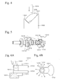
- an adjacent portion of the arm 1012 interferes with the punch 1002, so that the punch 1002 is inserted into the crankpin 1013 from an inclined direction (the direction indicated by the dashed arrowhead line in Fig. 5 ).
- a mark of abutting may remain on the portion abutting at the lower die 1001 in the one surface of the arm 1012 (the rightmost arm 1012 in Fig. 5 ).
- the radial direction (the directions indicated by the arrows in Fig. 6B ) of the crankpin 1013 is not restrained, so that dimensional accuracy of the crankpin 1013 is degraded by forming the holes 1013A and 1013B thereto.
- shrinkages of the opening end surfaces of the holes 1013A and 1013B occur in the axial direction of the crankpin 1013 and the material thereof is extended toward the radial direction (the direction indicated by arrows in Fig. 6B ). Therefore, balance of the arm 1012 must be corrected in a way such as forming plural holes (not shown) in the circumference of the counterweight of the arm 1012.
- coining may be performed by a forging apparatus perpendicularly moving with respect to the moving direction of the press ram.
- a forging apparatus perpendicularly moving with respect to the moving direction of the press ram.
- a forging apparatus having a side forming punch which is moved toward the perpendicular direction with respect to the moving direction of the press ram, may be used (For example, see Japanese Patent Application, First Publication No. 2007-245229 .).
- a cam mechanism is ordinarily used so that the cam mechanism having a simplified structure compared to a servomotor and oil pressure means can be disposed in the inside of a die set and can linearly follow movement of the press ram.
- Fig. 12 is a conceptual diagram for explanation of movement of a side-forming punch 2020 by a cam mechanism 2010.
- the cam mechanism 2010 is provided with a cam driver 2012 for driving cams 2011 and 2012, and a cam holder 2013 by which these members 2011 and 2012 are slidably held.
- a side-forming punch 2020 is provided at one side surface of the cam 2011 facing a die set and another side surface thereof on the opposite side to the die set is inclined.
- a bottom surface of the cam driver 2012 is disposed with a predetermined clearance with respect to the inclined surface of the cam 2011 in the initial condition of the cam driver 2012 and is inclined-surface slid with respect to the inclined surface of the cam 2011 in an operation of the cam 2011.
- crankshaft when the crankshaft is formed by this forging apparatus, the crankshaft must be disposed in the die set in a condition in which an axial direction of the crankshaft is perpendicular to the moving direction of the press ram, so that the side forming punch 2020 must be inserted into the crankpin from the axial direction of the crankshaft. Therefore, when the holes are formed in each crankpin of the crankshaft applied to a multiple-cylinder engine, the side-forming punches intersect.
- the cam 2011 is moved in conjunction with the movement of the press ram so that the side-forming punch 2020 provided to the cam 2011 is inserted and reaches to the deepest portion in the crankpin when the press ram reaches the bottom dead point.
- the press ram is moved toward a top dead point, and the side-forming punch is pulled out from the crankpin. Therefore, for example, as shown in Fig. 13 , when the hole 2044 is formed in each crankpin 2043 of the crankshaft 2040 having a full counterweight structure in a four-cylinder engine, side-forming punches 2021 and 2022 intersect each other and side-forming punches 2023 and 2024 also intersect each other (See areas framed by dashed lines in Fig.
- Reference numeral 2041 indicates a crankshaft and reference numeral 2042 indicates a crank arm in Fig. 13 .
- the side-forming using the cam mechanism cannot be applied to the forging for a crankshaft having a structure in which the side-forming punches intersect each other. Therefore, this intersection may be prevented by individual control with respect to the side forming punches using a servomotor and oil pressure means that are separate from the movement of the press ram as a driving source of the side-forming punch.
- a large space for setting a machine, such as an actuator is required, so that not only are workability and productivity degraded, but also the press equipment is larger so that a range of movement thereof is extended to the outside of the die set. This problem is a second object of the present invention.
- crankshaft production apparatus 3001 shown in Fig. 20 is used.
- the crankshaft production apparatus 3001 is provided with a transfer-type press machine 3010, a robot 3020, and a hollow forming press machine 3030.
- a main forming operation is performed with respect to a work W and the robot 2020 carries a preformed product P of the crankshaft obtained by the transfer-type press machine 3010 to the hollow forming press machine 3030, whereby the hollow forming is performed with respect to the preformed product P of the crankshaft.
- a press ram 3012 is disposed at an upper side of a press bolster 3011 and is facing thereto.
- An upset die set 3021, a rough forging die set 3022, a finishing die set 3022 and a trimming die set 3024 that can be vertically divided into upper dies and lower dies are disposed between the press bolster 3011 and the press ram 3012 in order of the forming operations toward the progressing direction thereof (toward the right hand direction in Fig. 20 ).
- the main forming operation upsetting, rough forging, finishing, and trimming operations
- the upper dies of the die sets 3021 to 3024 are moved toward the lower dies by the press ram.
- the lower dies of the die sets 3021 to 3024 are fixed on an upper surface of the press bolster 3011.
- Fig. 21 is a top view showing a schematic structure of the crankshaft production apparatus 3001 shown in Fig. 20 .
- Feed bars 3013 and 3014 and clamp clicks 3013A to 3013D and 3014A to 3014D shown in Fig. 21 are not shown in Fig. 20 .
- the feed bars 3013 and 3014 that are extended toward the forming operations progressing direction are provided. Only one punch of a hollow forming mechanism 3042 is shown in Fig. 20 for convenience.
- first clamp clicks 3013A to 3013D are provided and, in the second feed bar 3014, the second clamp clicks 3014A to 3014D are provided facing the first clamp clicks 3013A to 3013D.
- the first clamp clicks 3013A to 3013D and the second clamp clicks 3014A to 3014D are disposed along the extending direction of the feed bars 3013 and 3014 at a predetermined interval (the interval between the die sets).
- the first clamp clicks 3013A to 3013D and the second clamp clicks 3014A to 3014D hold the work W and are moved by the feed bars 3013 and 3014 along the extending direction thereof.
- the works W after the forming operations on the lower dies of each die set are held by the clamp clicks and are transferred to the next lower dies for the next forming operations (For example, see Japanese Patent Application, First Publication No. 2008-87048 .).
- a transfer-type press machine 3010 As shown in Figs. 22A to 22C , after disposing the works W1 and W2 in the die sets, operations such as die-set clamping, die-set opening, transferring the work W to the die set for the next forming operation, the die-set clamping in the next die set, and the die-set opening thereof are sequentially performed. In this case, each operation is performed by single press ram 3011, and the transfer to the next operation is performed by the feed bars 3013 and 3014.
- the work W1 which was subjected to finishing forming in the finishing die set 3023 is loaded into the trimming die set 3024.
- the trimming die set 3024 as shown in Fig. 22B , a burr B is punched out from the work W1 and the preformed product P of the crankshaft can be obtained.
- an upper die 3024A is downwardly moved toward the work W1 on a lower die 3024B, so that the burr B is punched out from the work W1 by the upper die 3024A and the burr holding die set 3024C on which the burr B of the work W1 is disposed.
- the preformed product P of the crankshaft can be obtained.
- the burr B that remained on the lower die 3024B is upwardly moved by the upward movement of the burr holding die set 3024C and is transferred to a burr conveyer 3015 in a condition in which the burr B is held by the clamp clicks 3013D and 3014D.
- the burr B is lifted by the burr holding die set 3024C of the lower die 3024B.
- the burr B is held by the clamp clicks 3013D and 3014D and is transferred to the burr conveyer 3015 by the feed bars 3013 and 3014.
- a hollow hole is formed in the preformed product P, so that the formed product can be obtained (the hollow forming operation).
- the hollow hole is formed for weight saving from the viewpoint of improvement of fuel efficiency. In this case, when the hole is formed in the crankpin, the rigidity of the crankshaft is not so decreased, so that the hole is formed in the crankpin.
- an upper die of a die 3041 is moved downward by a press ram 3032 toward a lower die on which the preformed product P is disposed.
- the preformed product P is closed in the die set 3041 and is inserted by a punch of a hollow forming mechanism 3042 from the perpendicular direction with respect to the moving direction of the press ram 3032.
- a driving source of the punch means such as a cam slide, an oil hydraulic cylinder, or a servomotor is used (For example, see Japanese Patent Application, First Publication No. 61-143727 .).
- reference numerals 3024L and 3041L indicate work holding cushions such as a spring, a gas cushion, or a hydraulic cushion
- reference numeral 3031 indicates a press bolster.
- the hollow forming press machine 3030 is separately used from the transfer-type press machine 3010, so that the production cost is increased and selectivity in the layout of the machines is degraded. Therefore, unification of the transfer type press machine 3010 and the hollow forming press machine 3030 may be performed so that the main forming operation and the hollow forming operation can be sequentially performed in a single apparatus (For example, the hollow forming die set 40341 is provided at the adjacent position on the forming operations progressing direction side of the trimming die set 3024 and the feed bars 3013 and 3014 are extended toward the forming operations progressing direction, whereby the clamp clicks are provided.).
- a loading position of the preformed product P is determined based on a pitch (moving amount) of the feed bars 3013 and 3014 and the pitch is fixed based on an interval between the die sets. Therefore, in the transfer by the feed bars 3013 and 3014, the pitch (the moving amount) at the hollow forming part cannot be individually modified, so that accuracy in loading the preformed product P into the hollow forming die set 3041 is degraded compared to the transfer by the robot 3020 by which the loading position of the preformed product P can be modified according to the position of the die set. Furthermore, in the hollow forming die set 3041, the clearance between the cavity for forming a finally required shape and the preformed product P is very small, so that an insertion of the preformed product P into the cavity is difficult.
- the single press ram 3012 is applied to each die set. Therefore, when adjustment of the thickness (the adjustment in the height direction) of the hole is individually performed by the modification of the shut-height in the hollow forming operation, such an adjustment in the height direction affects the other operations. As a result, selectivity of the material shape loaded in the hollow forming operation is lost. This problem is a third object of the present invention.
- a first object of the present invention is to provide a method for producing a crankshaft in which not only can weight saving be obtained by forming a hole in a crankpin, but also degradation of dimensional accuracy by forming the hole can be avoided.
- a second object of the present invention is to provide a crankshaft production apparatus and a production method therefor, in which plural holes can be formed at positions in which an intersection of side-forming punches occurs within one stroke of a press ram from a top dead point to a bottom dead point thereof in a case of using a cam mechanism as a driving source of the side-forming punches.
- a third object of the present invention is to provide a transfer-type crankshaft production apparatus and a production method therefor in which a main forming operation and a hollow forming operation can be sequentially performed.
- the present invention provides a method for producing a crankshaft of the first aspect of the invention including preforming the crankshaft provided with a crankpin, and forging the preformed product disposed in a cavity of a separatable die set composed of an upper die and a lower die; in which a shape of the preformed product of the crankshaft is formed smaller than a shape of the cavity in the performing, a hollow hole is formed in the crankpin by inserting a punch into the crankpin in the forging, thereby filling the cavity with a material of the preformed product.
- the preformed product of the crankshaft is forged using the separatable die set composed of the upper die and the lower die.
- the preformed product of the crankshaft is formed in a shape smaller than that of the cavity of the die set used in the forging.
- the die set is filled with a material of the forming product by the insertion of the punch into the crankpin, so that the required shape of the crankshaft can be obtained by forging in which the shape of the cavity of the die set is set so as to coincide with the required shape of the crankshaft.
- the corner portion around the opening of the hole is formed as an edge, so that finishing operation thereof by manual work may be additionally required to avoid concentration of stress at the edge.
- the corner portion around the opening of the hole is formed in a curved shape by a deformation resistance of the material in forging, so that the conventional finishing operation is unnecessary.
- the method for producing the crankshaft of the first aspect of the invention can be applied with variations in the structure.
- the upper die in forging, can be moved in a direction to which the upper die is opened according to the forming pressure in the die set.
- the upper die when the volume of the material of the preformed product is greater than the predetermined value, the upper die can be moved in the direction to which the upper die is opened according to forming pressure in the die set, so that the final required shape of the crankshaft can be obtained in such a case.
- the present invention provides a crankshaft production apparatus including a die set having a lower die, an upper die movably arranged with respect to the lower die, and plural side-forming punches perpendicularly movable with respect to a moving direction of the upper die; a press ram for closing and forming a material of the crankshaft in the die set by moving the upper die with respect to the lower die; a cam mechanism equipped to each side-forming punch for moving the side-forming punch toward an inside of the die set in conjunction with the movement of the press ram; an evacuating mechanism equipped to at least one of the side-forming punches for avoiding interference between the side forming punches and for canceling engagement between the movements of the press ram and the side forming punch via the cam mechanism.
- the material of the crankshaft is closed and formed in the die set by the movement of the press ram. Furthermore, the holes are formed at predetermined positions of the material by the movements of the side forming punches toward the inside of the die set, which are caused by the cam mechanism in conjunction with the movement of the press ram.
- the evacuating mechanism is provided to at least one of the side-forming punches to avoid interference between the side-forming punches with each other and for canceling the engagement between the movement of the press ram and the movement of the side-forming punch via the cam mechanism. Therefore, after the holes are formed by the movement of one of the side-forming punches toward the inside of the die set by the cam mechanism in conjunction with the movement of the press ram, the side-forming punch is moved toward the outward direction of the die set and can be moved back to an initial position thereof in a way such that the engagement between the side-forming punch and the movement of the press ram are cancelled by the evacuating mechanism.
- Another side-forming punch can be started to move toward the inside of the die set by the cam mechanism in conjunction with the movement of the press ram, so that the hollow hole can be formed by another side-forming punch without interference with one of the side-forming punches.
- the above technique for avoiding interference is applied as follows.
- the operation in the technique can be sequentially performed in order of movement of a first side-forming punch into the inside of the die set, evacuation of the first side-forming punch toward the outside of the die set, movement of a second side-forming punch into the inside of the die set, evacuation of the second side-forming punch toward the outside of the die set, a movement of a (N-1) side-forming punch into the inside of the die set, an evacuation of the (N-1) side-forming punch toward the outside of the die set and movement of an Nth side-forming punch into the inside of the die set.
- time-difference forming of plural holes in one operation of press ram from the top dead point to the bottom dead point thereof can be performed, so that the load for forming plural holes can be reduced to about half compared to the case in which the plural holes are simultaneously formed.
- the press equipment can be reduced in size.
- the cam mechanism that can be contained in the die set can be used as a driving source of the side-forming punch, so that a space for equipping an external device, such as an actuator for an individual control of the side-forming punches, is unnecessary. Therefore, the press equipment can be further reduced in size, and workability and productivity can be improved. Furthermore, a range of the movement of the side-forming punch can be restricted in the die set, so that there is no problem in operator safety.
- a method for producing a crankshaft of the second aspect of the invention includes a technique for side forming of plural holes by the crankshaft production apparatus in accordance with a second aspect of the present invention. That is, a method for producing the crankshaft in accordance with the second aspect of the present invention includes providing a die set having a lower die, an upper die movably arranged with respect to the lower die, and plural side-forming punches perpendicularly movable with respect to a moving direction of the upper die; forming a material of the crankshaft closed in the die set by a movement of a press ram, and forming holes in predetermined positions of the material by movement of each side-forming punch via a cam mechanism toward an inside of the die set in conjunction with the movement of the press ram, in which the material having a structure causing intersection of the side-forming punches with each other is used in forming the hole in the material by the side-forming punches, and one side-forming punch is evacuated by the evacuating mechanism for canceling engagement
- a crankshaft production apparatus of the third aspect of the invention includes a first vertically separatable die set composed of an upper die and a lower die for preforming a material of the crankshaft; a second vertically separatable die set composed of an upper die and a lower die in which the preformed product obtained by the first vertically separatable die set is closed and is formed with a hollow hole by inserting a punch into a predetermined portion of the preformed product; a press ram closing the first vertically separatable die set and the second vertically separatable die set by the movement of the upper dies of the first vertically separatable die set and the second vertically separatable die set toward the lower dies thereof; a shim provided to the second vertically separatable die set for adjusting a position in a horizontal direction thereof; and a liner portion provided to the second vertically separatable die set for adjusting a position in a height direction thereof.
- the shim is provided to the second vertically separatable die set for adjusting the horizontal position thereof, so that the horizontal position of the second vertically separatable die set can be adjusted by the shim according to the loading position of the preformed product into the second vertically separatable die set.
- Such an adjustment of the horizontal position can be individually performed from the first vertically separatable die set, so that the adjustment does not affect the operation in the first vertically separatable die set.
- the liner portion is provided for adjusting the height position thereof, so that a thickness adjustment (the adjustment in a height direction) of the hole required in forming the hole in the second vertically separatable die set can be taken care of by the height adjustment of the second vertically separatable die set by the liner portion.
- This height adjustment can be individually performed from the first vertically separatable die set, so that the adjustment does not affect the preforming operation in the first vertically separatable die set. Therefore, not only can the upper dies of the first vertically separatable die set and the second vertically separatable die set be moved toward the lower dies thereof by a single press ram, but also selectivity of the material shape loaded into the second vertically separatable die set can be improved.
- crankshaft production apparatus of the third aspect of the invention when the main forming operation containing upsetting, rough forging, finishing, and trimming is performed in the first vertically separatable die set, and the hollow forming operation is performed in the second vertically separatable die set, these forming operations can be sequentially performed by the fixed-pitch feed bars and single press ram.
- a transfer type press apparatus having such a structure can be constructed, so that the cost can be reduced and selectivity of the layout of the equipments in the apparatus can be upgraded.
- the crankshaft production apparatus of the third aspect of the invention can be applied with variations of the structure.
- a burr-ejecting portion for ejecting a burr formed in forming the preformed product by the first vertically separatable die set can be applied to the crankshaft production apparatus of the third aspect of the invention.
- the burr-ejecting portion can be provided with a burr stage provided at a position between the first vertically separatable die set and the second vertically separatable die set and a burr ejecting portion for ejecting the burr provided in a direction different from the direction from the burr stage toward the second vertically separatable die set.
- the hollow forming die set 3041 when the hollow forming die set 3041 is adjacently provided at the forming progressing direction side of the trimming die set 3024 shown in Fig. 20 , and the feed bars 3013 and 3014 are extended toward the forming progressing direction for additional providing of the clamp clicks thereon, the hollow forming die set 3041 includes a hollow forming mechanism 3042 (composed of punches and a driving source), so that a burr holding mechanism (composed of a burr holding die set 3024C and a burr pressing member 3024D) of the trimming die set 3024 shown in Figs. 23A and 23B cannot be provided at the forming progressing direction side of the trimming die set 3024.
- a burr holding mechanism Composed of a burr holding die set 3024C and a burr pressing member 3024D
- the burr B may be directly conveyed toward the outside of the forming progressing direction by the clamp clicks of the feed bars 3013 and 3014 shown in Fig. 21 , avoiding the hollow forming die set 3041, and the interval between the clamp clicks is fixed based on the interval between the die sets, so that this specific transfer by the feed bars 3013 and 3014 cannot be modified.
- the burr formed in forming the preformed product can be transferred to the burr stage of the burr ejecting portion and can be ejected from the burr ejecting portion of the burr ejecting portion toward the direction different from the direction toward the second vertically separatable die set.
- the clamp clicks are particularly provided at the positions on the feed bars corresponding to the work, so that not only a transference of the work, but also a transference of the burr to the burr stage of the burr-ejecting portion, can be performed by the feed bars.
- the modification of the conventional specifications, such as the interval between the clamp clicks is unnecessary.
- the burr-ejecting portion is preferably disposed at the rear side of the apparatus.
- a coating apparatus for applying a separating compound to the die set is disposed.
- the burr-ejecting portion can be disposed below the coating apparatus, avoiding the coating apparatus.
- a method for producing the crankshaft of the third aspect of the invention includes a technique in which the main forming operation in the first vertically separatable die set and the hollow forming operation in the second vertically separatable die set are sequentially performed by the crankshaft production apparatus of the present invention using the single press ram and transfer by the feed bar.
- the method for producing a crankshaft of the third aspect of the invention includes preforming a material of the crankshaft closing the material in a first separatable die set, and forming a hole by closing a preformed product in a second separatable die set and inserting a punch provided to the second separatable die set into the predetermined portion of the preformed product, in which a first vertically separatable die set and a second vertically separatable die set are closed by moving the upper dies of the first separable die set and the second separatable die set toward the lower dies thereof by a press ram; a position in a horizontal direction of the second separatable die set is adjusted by a shim and a position in a height direction of the second separatable die set is adjusted by a liner portion.
- the crankshaft production apparatus and the production method of the second aspect of the invention even though the cam mechanism is used as the driving source of the side forming punch, the plural holes can be formed with time-difference within one operation of the press ram from the top dead point to the bottom dead point thereof. Therefore, an effect such as reduction in size of the press equipment can be obtained.
- crankshaft production apparatus and the production method of the third aspect of the invention when the main forming operation containing upsetting, rough forging, finishing, and trimming is performed in the first vertically dividing die set and the hollow forming step is performed in the second vertically separatable die set, an effect such that these forming operations can be sequentially performed by the fixed-pitch feed bars and single press ram can be obtained.
- Fig. 1 is a conceptual diagram for an explanation of movement of a forging apparatus 1100 used in a method for producing a crankshaft of the first embodiment.
- each portion of the forging apparatus 1100 (especially a die set 1103) is simply shown.
- a press bolster 1101 is provided thereto and a press ram 1102 is held above the press bolster 1101.
- a die set 1103 is disposed between the press bolster 1101 and the press ram 1102.
- the die set 1103 is provided with a lower die 1103A, an upper die 1103B and side-forming punches 1111p and 1112p.
- the upper die 1103B is movably arranged with respect to the lower die 1103A.
- Reference numeral 1104 in Fig. 2 is a load-adjusting portion (an oil or an air pressure means) for adjusting the initial load with respect to the upper die 1103B.
- a material M is disposed in the die set 1103. When the volume of the material M is greater than a predetermined value, the upper die 1103B is moved toward an opening direction (an upward direction) according to the forming pressure in the die set 1103.
- the side-forming punches 1111p and 1112p are movably provided toward the perpendicular direction with respect to the moving direction of the upper die 1103B.
- the side-forming punches 1111p and 1112p can be inserted into the die set 1103 and can be pulled out therefrom through a punching hole (not shown) formed in a side portion of the die set 1013.
- the side-forming punches 1111p and 1112p are provided with cam mechanisms 1111 and 1112 by which the side-forming punches 1111p and 1112p are moved into the die set 1103 in conjunction with the movement of the press ram.
- the cam mechanisms 1111 and 1112 are provided with cams 1111c and 1112c and cam drivers 1111d and 1112d for driving the cams 1111c and 1112c.
- the side-forming punches 1111p and 1112p are provided at each one side surface, which faces the die set 1103, of cams 1111c and 1112c. Other side surfaces of the cams 1111c and 1112c, which face the opposite sides to the die set 1103, are inclined.
- the bottom surfaces of the cam drivers 1111d and 1112d are inclined surfaces which are disposed via a predetermined interval with respect to the inclined surfaces of the cams 1111c and 1112c in the initial condition of the cam drivers.
- the cam drivers 1111d and 1112d are downwardly moved according to a downward movement of the press ram 1102 and the bottom surfaces of the cam drivers 1111d and 1112d contact to the inclined surfaces of the cams 1111c and 1112c, whereby these surfaces thereof slide relative to each other.
- the cam mechanisms 1111 and 1112 are provided with evacuating members 1111s and 1112s. After finishing the side-forming by the side-forming punches 1111p and 1112p when the press ram is disposed at the bottom dead point thereof, the cam drivers 1111d and 1112d are moved upward according to the upward movement of the press ram toward the top dead point, so that the side-forming punches 1111p and 1112p are evacuated toward the outside of the die set 1103 by the evacuating members 1111s and 1112s and are moved back to the initial positions thereof.
- an axial direction of a journal shaft is perpendicularly set with respect to the moving direction of the press ram.
- a crankpin is disposed in a parallel direction with respect to the journal shaft, so that one surface of the crankpin (the perpendicular surface with respect to the journal shaft) faces the side-forming punches 1111p and 1112p.
- the preformed product of the crankshaft is formed in a shape smaller than a required shape of the crankshaft and a shape of a cavity of the die set 1103 is set so as to coincide with the required shape of the crankshaft.
- a preformed product of the crankshaft is disposed in the cavity of the die set 1103.
- the cam drivers 1111d and 1112d are downwardly moved according to the downward movement of the press ram 1102, so that the inclined surfaces of the cam drivers 1111d and 1112d contact the inclined surfaces of the cams 1111c and 1112c.
- These inclined surfaces slide relative to each other by the further downward movement of the press ram 1102, so that the side-forming punches 1111p and 1112p are moved into the inside of the die set 1103 along the horizontal direction.
- holes are formed in the crankpin of the preformed product by the side-forming punches 1111p and 1112p.
- the preformed product when used as a material M, the preformed product, which is formed in a shape smaller than the required shape (that is, the shape of the cavity of the die set 1103) of the crankshaft, is disposed in the cavity of the die set 1103.
- Fig. 2 is a conceptual diagram for explanation of a method for producing the crankshaft of the first embodiment and the case of forming the hole by one side-forming punch 1000p is shown in Fig. 2 .
- a downward arrowhead indicates a direction of a confining pressure of the die set 1103 with respect to the material M and the upward arrowed lines in Fig. 2 indicate the loading direction of the material M.
- the cavity of the die set 1103 can be filled with the material, so that the required shape of the crankshaft can be obtained by the forging in a way such that the shape of the cavity of the die set 1103 is set so as to coincide with the required shape of the crankshaft.
- the crankshaft not only can weight saving be obtained by forming the hole in the crankpin, but also dimensional accuracy of the crankshaft can be improved by the forging in this closed space, so that balance correction such as forming plural holes in a counterweight is unnecessary.
- an edge portion around an opening of the hole is curved by a deformation resistance in forging of the material, so that conventional finishing operation is also unnecessary.
- the upper die 1103B can be moved toward the opening direction according to the forming pressure in the die set 1103, so that the required shape of the crankshaft can be obtained in this case.
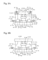
- FIG. 7 and Figs. 8A and 8B are views showing schematic structures of a crankshaft production apparatus 2100.
- Fig. 7 is a schematic top view showing the total structure of the crankshaft production apparatus 2100
- Fig. 8A is a schematic cross-sectional side view showing a structure taken along a line 8A to 8A' in Fig. 7
- Fig. 8B is a schematic cross-sectional side view showing a structure taken along a line 8B to 8B' in Fig. 7 .
- Fig. 7 and Figs. 8A and 8B for convenience of showing views, omission and simplification in views of each portion are made.
- a press ram 2104 and a load adjusting portion 2105 are omitted in Fig. 7
- an upper die 2103A and a lower die 2103B of a die set 2102 and cam holders 2113h to 2116h are simply shown in Figs. 8A and 8B .
- relative positions of the side-forming punches 2111p to 2118p and the cam mechanisms 2111 to 2118 are not exactly shown in Fig. 7 .
- the crankshaft production apparatus 2100 is provided with, for example, a press bolster 2101, and the press ram 2102 is held above the press bolster 2101.
- the die set 2103 is disposed between the press bolster 2101 and the press ram 2102.
- Reference numeral 2104 in Fig. 7 shows one surface of a bed on which the press bolster 2101 is disposed.
- the die set 2103 is provided with the lower die 2103A, the upper die 2103B and the side-forming punches 2111p to 2118p.
- a preformed product 2200 is disposed in the die set 2103.
- the preformed product 2200 is provided with a journal shaft 2201 and an arm 2202 is provided to the journal shaft 2201.
- the adjacent arms 2202 are connected to each other via a crankpin 2203 disposed in the parallel direction with respect to the journal shaft 2201.
- the crankpin 2203 is disposed in the parallel direction with respect to the journal shaft 2201.
- a cavity surface of the die set 2103 has a shape coinciding with the shape of the preformed product 2200.
- the upper die 2103B is movably provided with respect to the lower die 2103A.
- Reference numeral 2105 is a load-adjusting portion (the portion driven by oil or air pressure means) for adjusting the initial load with respect to the upper die 2103B.
- the side forming punches 2111p to 2118p are movably provided in the perpendicular direction with respect to moving direction of the upper die 2103B.
- the side-forming punches 2111p to 2118p can be inserted into the inside of the die set 2103 and can be removed therefrom through punching holes (not shown) formed in the side portions of the die set 2103.
- the side forming punches 2111p to 2118p are provided to the cam mechanisms 2111 to 2118 for moving the side-forming punches 2111p to 2118p into the die set 2103 in conjunction with the movement of the press ram 2102.
- the cam mechanisms 2111 to 2118 are provided with the cams 2111c to 2118c, the cam drivers for driving the cams and cam holders 2111h to 2118h by which the cams and the cam drivers are slidably held.
- the side-forming punches 2111p to 2118p are provided at side surfaces of the cams 2111c to 2118c facing the die set 2103.
- Other side surfaces of the cams 2111c to 2118c, which are on the side opposite to the die set 2103 are inclined surfaces.
- the bottom surfaces of the cam drivers are inclined surfaces sliding with respect to the inclined surfaces of the cams 2111c to 2118c.
- the cam mechanisms 2111 to 2118 when the upper die 2103B is moved downward by the press ram 2102, the inclined surfaces of the cam drivers and those of the cams 2111c to 2118c contact each other. These inclined surfaces slide relative to each other by the further downward movement of the press ram 2102, so that the side forming punches 2111p to 2118p are moved into the inside of the die set 2103 along the horizontal direction.
- the cam drivers of the cam mechanisms 2111 to 2114 are disposed so as to be perpendicularly movable via passing through holes 2102A of the press ram 2102.
- each cam driver is held in the passing through hole 2102A by holding members described below until finishing of the forming by the side-forming punches corresponding to the cam drivers.
- the holding positions of the cam drivers with respect to the inclined surfaces of the cams are set above the holding positions of the cam drivers of the cam mechanisms 2111 to 2114 with a predetermined distance therefrom.
- the cam drivers 2113d and 2114d of the cam mechanisms 2113 and 2114 and holding members 2113v and 2114v are shown in Fig. 8A .
- cam mechanisms 2111 and 2112 are provided with the cam drivers and the holding members having the same structures as those of the cam mechanisms 2113 and 2114.
- the cam drivers 2115d and 2116d of the cam mechanisms 2115 and 2116 are shown in Fig. 8B and the cam mechanisms 2117 and 2118 are provided with the cam drivers having the same structure as the cam drives of the cam mechanisms 2115 and 2116.
- the cam evacuating mechanisms are provided for evacuating the side forming punches 2111p to 2114p toward the outside of the die set 2103 after finishing the side forming on the way from the top dead point to the bottom dead point of the press ram 2102.
- the cam evacuating mechanisms are provided with first evacuating members, second evacuating members and the holding members described in the above.
- the first evacuating members are elastic members formed at, for example, the side surfaces of the cams 2111c to 2114c on the side opposite to the die set 2103.
- the second evacuating members are elastic members formed on, for example, the upper surface of the cam drivers.
- the holding members are moved from the position on the upper surfaces of the cam drivers into evacuating holes 2102B for canceling the engagements between the press ram 2102 and the cams 2111c to 2114c after finishing the forming of the side forming punches 2111p to 2114p.
- the cam drivers are moved upward by the second evacuating members, so that the cams are evacuated toward the side opposite to the die set 2103 by the first evacuating members.
- the first elastic members 2113s and 2114s of the cam mechanisms 2113 and 2114 and the second elastic members 2113t and 2114t are shown in Fig. 8A , and the cam mechanisms 2111 and 2112 are provided with the first elastic members and the second elastic members having the same structures as the first and second elastic members of the cam mechanisms 2113 and 2114.
- the cam evacuating mechanisms are provided for evacuating the side forming punches 2115p to 2118p from the die set 2103 toward the outside thereof after finishing the side forming when the press ram 2102 is positioned at the bottom dead point thereof.
- the cam evacuating mechanisms are provided with the first evacuating members.
- the first evacuating members 2115s and 2116s of the cam mechanisms 2115 and 2116 are shown in Fig. 8B , and the cam mechanisms 2117 and 2118 are provided with the first evacuating members having the same structures as the first evacuating members of the cam mechanisms 2115 and 2116.
- a load acting on the die set 2103 by which the preformed product 2200 can be held avoiding deformation thereof in forming the holes is, for example, about 400 tons.
- a load in forming the hole is, for example, about 100 tons depending on a shape and a cross-sectional area thereof, because the way of processing is forging. Therefore, in the crankshaft production apparatus 2100, press working of about a 1200-ton load as a total load for forming is required.
- the die set 2103 and the cam mechanisms 2111 to 2118 are disposed and held in the die set for the press working in the above conditions.
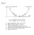
- FIG. 9 is a graph showing a time dependence of a stroke of a press ram 2102 of the crankshaft production apparatus 2100 shown in Fig. 7 and Figs. 8A and 8B , and the graph is for an explanation of each movement of the side-forming punches 2111p to 2118p in varying the stroke of the press ram 2102.
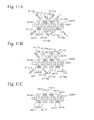
- Figs. 10A to 10C and Figs.
- FIG. 11A to 11C are schematic top views showing each movement of the side-forming punch 2111p to 2118p in varying the stroke of the press rams 2102 shown in Fig. 9 .
- the movements of the side-forming punches 2113p and 2114p using the cam mechanisms 2113 and 2114 are the same as the movements of the side-forming punches 2111p and 2112p using the cam mechanisms 2111 and 2112.
- the movements of the side-forming punches 2115p and 2116p using the cam mechanisms 2115 and 2116 are the same as the movements of the side-forming punches 2117p and 2118p using the cam mechanisms 2117 and 2118. Therefore, in the following explanation, the movements of the side-forming punches 2111p, 2112p, 2117p and 2118p are mainly explained.
- the preformed product 2200 is disposed in a die set 2103.
- the side-forming punches 2111p to 2118p are held at the outside of the die set 2102 in the initial conditions thereof (the condition of reference symbol 4A in Fig. 9 ).
- the cam drivers of the cam mechanisms 2111 to 2118 are moved downward according to a downward movement of the press ram 2102 from the top dead point toward the downward direction.
- crankpin 2203 of the preformed product 2200 is processed by side-forming of the side-forming punches 2111 to 2114, whereby the holes 2211 to 2214 are formed (the condition of reference symbol 4B in Fig. 9 ).
- the inclined surfaces of the cam drivers of the cam mechanisms 2115 to 2118 are upwardly positioned compared to the cam drivers of the cam mechanisms 2111 to 2114, and are detached to the inclined surfaces of the cams 2115c to 2118c.
- the stroke lengths of the cams 2111c to 2114c become longest (the point of reference symbol Q in Fig. 9 ) and forming the holes 2211 to 2214 by the side-forming punches 2111p to 2114p is finished. Furthermore, the holding members (in the cam mechanisms 2113 and 2114, reference symbols 2113v and 2114v in Fig. 8A ) holding the upper surfaces of the cam drivers are moved into evacuating holes 2102B of the press ram 2102, so that the engagement between the press ram 2102 and the cams 2111c to 2114c is cancelled.
- the cam drivers are moved upward through the through holes 2102A by the second evacuating members (in the cam mechanisms 2113 and 2114, reference symbols 2113t and 2114t in Fig. 8A ), and, as shown in Fig. 10C , the cams 2111c to 2114c are evacuated toward the outside of the die set 2103 by the first evacuating members (the condition of reference symbol 4C in Fig. 9 ).
- crankshaft 2200 in which the holes 2211 to 2218 are formed is removed from the die set by the operation of the ejector pin (the point of reference symbol U in Fig. 9 ).
- time-difference forming of the plural holes 2211 to 2218 can be performed in one operation of the press ram 2102 from the top dead point to the bottom dead point by using such a technique for avoiding interference between the punches, so that a load for forming the plural holes 2211 to 2218 can be reduced to about half compared to the case in which the plural holes 2211 to 2218 are simultaneously formed. As a result, reduction in size of the press equipment can be performed.
- the cam mechanisms 2111 to 2118 which can be held in the die set, can be used as a driving source of the side-forming punches 2111p to 2118p, so that a space for setting an external apparatus such as an actuator for independent control of the side forming punches 2111p to 2118p is unnecessary. Therefore, further reduction in size of the press equipment can be performed, and workability and productivity can be improved. Furthermore, a moving range of the side-forming punches 2111p to 2118p can be set in the inside of the die set, so that there is no problem with worker safety.
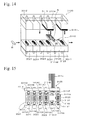
- FIG. 14 is a conceptual diagram showing a schematic structure of a crankshaft production apparatus 3100 in accordance with the third embodiment.
- Fig. 15 is a schematic top view showing a partial structure containing feed bars 3013 and 3014 of the crankshaft production apparatus 3100 shown in Fig. 14 .
- the feed bars 3013 and 3014, clamp clicks 3013A to 3013D, 3113E, 3113F, 3014A to 3014D, 3114E, and 3114F shown in Fig. 15 are not shown in Fig. 14 .
- FIG. 14 For convenience, only one punch of a hollow forming mechanism 3142 shown in Fig. 15 is shown in Fig. 14 .
- the same reference symbols as those in Figs. 20 to 23B indicate the same components as those in Figs. 20 to 23B , and explanation of the component is omitted.
- the crankshaft production apparatus 3100 is an apparatus in which main forming operations (upsetting, rough forging, finishing and trimming operations) performed by the conventional transfer-type press apparatus 3010 shown in Figs. 20 to 23B , and a hollow forming operation performed by the conventional hollow forming apparatus 3030, are sequentially performed by using the same single press ram 3012 and the fixed-pitch feed bars 3013 and 3014.
- a burr-ejecting portion 3125 and a hollow forming die set 3126 are sequentially provided at the forming progressing direction side (the right-hand side in the Figures) of a trimming die set 3024 of the conventional transfer-type press apparatus 3010. Furthermore, according to newly providing these portions 3125 and 3126, the pres ram 3012 and the feed bars 3013 and 3014 are extended toward the forming progressing direction side (the right-hand side in the Figures).
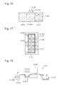
- the hollow forming portion 3126 is provided with a liner portion 3131 shown in Fig. 16 and a shim 3132 shown in Fig. 17 .
- a burr conveyer 3115 is provided to the burr-ejecting portion 3125 instead of the burr conveyer 3015 of the conventional transfer type press apparatus 3010.
- the burr-ejecting portion 3125 is provided with a burr stage 3125S, the burr conveyer 3115 and a robot 3140.
- the burr stage 3125S is fixed to the press bolster 3011.
- a disposing portion 3125M on which the burr B and the preformed product P transferred from the trimming die set 3024 are disposed is provided on the upper surface of the burr stage 3125S.
- the burr conveyer 3115 is disposed at, for example, the rear side of the burr stage 3125S and ejects the burr B toward the outside of the apparatus.
- the robot 3140 lifts the burr B on the disposing portion 3125M using a clamp click 3140A and carries the burr B to the burr conveyer 3115.
- a method for carrying the burr B to the burr conveyer 3115 is not restricted by the robot 3140 but may be applied with modifications of the carrying methods.
- a moving mechanism by which the burr conveyer 3115 is approached with respect to the burr stage 3125S may be provided to the structure so that the burr B on the disposing portion 3125M can be removed therefrom by the burr conveyer 3115.
- the hollow forming die set 3126 is a vertically separatable type of die set. A lower die of the hollow forming die set 3126 is fixed to a press bolster 11 and an upper die is fixed to the press ram 3012.
- the hollow forming die set 3126 is provided with a hollow forming mechanism 3142 and a work holding cushion 3131L having the same structures as the hollow forming mechanism 3042 and the work holding cushion 3031L shown in Fig. 20 .
- a liner portion 3131 for adjusting a height position of the hollow forming die set 3126 is provided.
- the liner portion 3131 is disposed below the bottom of the lower die.
- a plate material having the thickness of which a dimension is equivalent to, for example, a preferable amount of the height adjustment for the lower die is used. In this case, the plural plate materials may be used and are appropriately inserted and removed according to the amount of the height adjustment.
- the liner portion 3131 is also provided to the upper die as necessary.
- the shim 3132 for adjusting the position in the horizontal direction of the hollow forming die set 3126 is provided.
- the shim 3132 is a plate material disposed on, for example, the circumference of a shaping die portion 3126A of the lower die.
- the shim 3132 is inserted and removed from at least one of the directions of the front side (the lower side in Fig. 17 ), the rear side (the upper side in Fig. 17 ), the forming progressing direction side (the right-hand side in Fig. 17 ) and the side opposite to the forming progressing direction (the left-hand side in Fig.
- the shim 3132 is also provided to the upper die and is correspondingly positioned with respect to the shim 3132 of the lower die.
- a first feed bar 3013 is provided with first clamp clicks 3113E and 3113F and a second feed bar 3014 is provided with second clamp clicks 3114E and 3114F.
- the clamp clicks 3113E and 3114E are disposed facing the burr stage 3125S and the clamp clicks 3113F and 3114F are disposed facing the hollow forming die set 3126.
- the works W are held by the first clamp clicks 3113E and 3113F and the second clamping clicks 3114E and 3114F and are moved by first and second feed bars along the extending direction thereof.
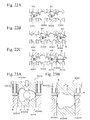
- FIGS. 19A to 19D are conceptual diagrams showing sequentially forming operations performed by the crankshaft production apparatus 3100.
- crankshaft production apparatus 3100 As shown in Figs. 19A to 19D , from the viewpoints of load and cooling in the forming press work, die-set clamping, die-set opening and transferring the works W to the die sets of the next operations, die set clamping, die set opening are sequentially performed in a condition in which the works W1, W2 and W3 are disposed therein with an interval of one operation. In this case, upsetting, rough forging, finishing, trimming and hollow forming operation are performed by single press ram 3012, and the works W1 and W2 are transferred by a pair of feed bars 3023 and 3024.
- the work W1 of which a finishing operation is completed in a finishing die set 3023 is held by the clamp clicks 3013C and 3014C (shown only in Fig. 15 ) after an upward movement of the press ram 3012 and is transferred to a trimming die set 3024 by the feed bars 3013 and 3014 (shown only in Fig. 15 ).
- the work W2 of which a rough forging operation is completed in a rough forging die set 3021 is held by the clamp clicks 3013A and 3014A (shown only in Fig. 15 ) and is transferred to an upsetting die set 3022 by the feed bars 3013 and 3014.
- the trimming operation with respect to the work W1 is performed by the downward movement of the press ram 3012. Specifically, the burr B is punched out from the work W1, so that the preformed product P can be obtained.
- the upsetting operation with respect to the work W2 is performed by the downward movement of the press ram 3012.
- the preformed product P in the trimming die set 3024 is held by the clamp clicks 3013D and 3014D (shown only in Fig. 15 ) and is transferred to the burr ejecting portion 3125 by the feed bars 3013 and 3014, so that the preformed product P is disposed on the disposing portion 3125M.
- the burr B is remained in the trimming die set 3024.
- the work W2 in the upsetting die set 3022 is held by the clamp clicks 3013B and 3014B (shown only in Fig. 15 ) and is transferred to the finishing die set 3023 by the feed bars 3013 and 3014.
- the finishing operation with respect to the work W2 is performed in the finishing die set 3023, after the upward movement of the press ram 3012, as shown in Fig. 19C , the preformed product P is held by the clamp clicks 3113E and 3114E in the burr ejecting portion 3125 and is transferred to a hollow forming die set 3126 by the feed bars 3013 and 3014.
- the hollow forming die set 3126 is provided with a shim 3132 for adjusting the position in the horizontal direction thereof, so that the position in the horizontal direction of the hollow forming die set 3126 can be adjusted by the shim 3132 according to a loading position of the preformed product P into the hollow forming die set 3126. Therefore, when the clearance between the surface of the cavity of the hollow forming die set 3126 and the preformed product P is very slight, the preformed product P can be easily inserted into the cavity of the hollow forming die set 3126. Furthermore, such an adjustment in the horizontal direction can be individually performed from the die sets 3021 to 3024 and the burr stage 3125A, so that the adjustment does not affect each operation in the die sets 3021 to 3024 and burr stage 3125A.
- a burr holding die set 3024C is upwardly moved from the lower die thereof according to the upward movement of the press ram 3012, so that the burr B remaining in the trimming die set 3024 is lifted.
- the burr B is held by the clamp clicks 3013D and 3014D and is transferred to the burr ejecting portion 3125 so as to be disposed on the burr disposing portion 3125M.
- the work W2 in the finishing die set 3023 is held by the clamp clicks 3013C and 3014C and is transferred to the trimming die set 3024.
- the upper die thereof is moved downward by the press ram 3012 toward the lower die on which the preformed product P is disposed.
- the preformed product P is not only closed in the die set 3126 but also inserted by the punch of the hollow forming mechanism, so that the preformed product P in which the hole H is formed can be obtained.
- the trimming die set 3024 the trimming operation with respect to the work W2 is performed and the burr B is punched out from the work W2 by the downward movement of the press ram 3012, so that the preformed product P of the crankshaft can be obtained.
- the hollow forming die set 3126 is provided with a liner portion 3131 for adjusting the position in the height direction, so that adjusting a thickness (adjusting in the height direction) of the hole H required in forming the hole H in the hollow forming die set 3126 can be performed by adjusting the height of the hollow forming die set 3126 by the liner portion 3131.
- a height adjustment can be individually performed from the die sets 3021 to 3024, so that the height adjustment does not affect each forming operation in the die sets 3021 to 3024.
- the preformed product P in the hollow forming die set 3126 is held by the clamp clicks 3113F and 3114F (shown only in Fig. 15 ) and is transferred to the outside of the apparatus by the feed bars 3013 and 3014.
- the burr B in the burr-ejecting portion 3125 is ejected to the burr conveyer 3115 by a click 3140A of a robot 3140 shown in Fig. 18 .
- the preformed product P formed from the work W2 in the trimming die set 3023 is held by the clamp clicks 3013D and 3014D and is transferred to the burr ejecting portion 3125 by the feed bars 3013 and 3014, so that the preformed product P is disposed on the disposing portion 3125M.
- the burr B obtained by processing with respect to the work W2 is remained in the trimming die set 3024.
- the work W2 is processed in the same way as the processing with respect to the work W1
- the work W3 loaded into the apparatus with an interval of one operation with respect to the work W2 is processed in the same way as the processing with respect to the works W1 and W2, so that the formed products of the crankshafts can be sequentially obtained.
- the horizontal position of the hollow forming die set 3126 can be adjusted by the shim 3132, so that the preformed product can be easily inserted into the cavity of the hollow forming die set 3126. Furthermore, the horizontal adjustment by the shim 3132 does not affect each operation in the die sets 3021 to 3024 and the burr stage 3125, so that the works (the material of the crankshaft, the preformed product and the formed product of the crankshafts) can be transferred by a pair of feed bar 3013 and 3014 of which the pitches are fixed.
- the height adjustment of the hollow forming die set 3126 by the liner portion 3131 can be performed without effecting each operation in the die sets 3021 to 3024, so that the upper dies of the die sets 3021 to 3024 and 3126 can be moving downward toward the lower dies thereof by single press ram 3012 and the selectivity of the shape of the material loaded into the hollow forming die set 3126 can be improved.
- each forming operation can be sequentially performed by the feed bars 3013 and 3014 of which the pitches are fixed and single press ram 3012 in single apparatus 3100, so that production cost can be reduced and selectivity of the layout of the apparatus can be upgraded.
- the burr B can be ejected toward a direction different from the direction from the burr conveyer 3115 to the hollow forming die set 3126.
- the clamp clicks 3113E and 3114E are additionally provided to the feed bars 3013 and 3014 and are disposed at the positions thereon corresponding to the burr ejecting portion 3125, so that not only the transfer of the works, but also the transfer of the burr B to the burr stage 3125S of the burr ejecting portion 3125, can be performed by the feed bars 3013 and 3014. Therefore, modification of the specifications such as an interval length between the clamp clicks is unnecessary.
- a hole 1200A was formed in a material 1200 by inserting a punch thereinto.
- Fig. 3 is a top view of the material 1200.
- a required dimension of a width w1 was set at 70.1 mm, and that of a width w2 was set at 50.2 mm.
- a method for producing the crankshaft of the first embodiment shown in Fig. 2 was used. Specifically, the material 1200 having a shape smaller than a final shape thereof was disposed in the die set. A shape of an inner surface of the die set was matched with a required shape of the material 1200. The hole 1200A was formed in the material 1200 by inserting the punch thereinto. As a result, in the material 1200 after forming the hole 1200A, the dimension of the width w1 was 70.8 mm (the difference from the required value was 0.7 mm) and the dimension of the width w2 was 50.4 mm (the difference from the required value was 0.2 mm). The surface shrinkage (the reduction of the height of the end surface 1201 in the vertical direction on a plane of paper) of the end surface 1201 in the vicinity of the hole 1200A of the material 1200 was 0.1 mm.
- a material 1200 was disposed on an inclined surface 1301 of a lower die 1300 and the hole 1200A was formed on the material 1200 by inserting a punch 1002 thereinto.
- the punch 1002 was inserted, the material 1200 was depressed by inclined surfaces 1301 and 1302, but the other portions except for the depressed portions were not restricted.
- the dimension of the width w1 was 75.4 mm (the difference from the required value was 5.3 mm) and the dimension of the width w2 was 51.3 mm (the difference from the required value was 1.1 mm).
- the surface shrinkage of the end surface 1201 in the vicinity of the hole 1200A of the material 1200 was 2.0 mm.
- the width W1, the width W2 and the surface shrinkage thereof were smaller than those of the comparative experimental example. Therefore, in the method for producing the crankshaft of the first aspect of the invention, when the hole is formed, dimensional accuracy of the portion in the vicinity of the hole can be improved and surface shrinkage can be avoided.
Landscapes
- Engineering & Computer Science (AREA)
- Mechanical Engineering (AREA)
- Forging (AREA)
Abstract
Description
- The present invention relates to a method for producing a crankshaft having a hollow hole, and relates to a production apparatus therefor.
- A crankshaft of an internal-combustion engine is provided with a journal shaft. A crankpin that is parallel to the journal shaft is connected thereto via an arm. A counterweight is formed in the arm, and the forming position of the counterweight with respect to the journal shaft is at the opposite side to the connecting position of the crankpin.
- In the crankshaft, from the viewpoint of improvement of fuel efficiency, weight saving by forming a hollow hole in the crankpin may be performed. When the hollow hole is formed in the crankpin, rigidity of the crankshaft is slightly affected by the forming of the hole, so that the hole is preferably formed in the crankpin. As a method for forming the hole, machining, and a method in which a crankpin is formed from a tubular material and is connected to a main body of the crankshaft, may be exemplified. In both methods, complicated steps are required, so that the production cost is higher. For reducing the production cost, forming of the main body of the crankshaft and forming the hole are effectively performed by forging. However, the crankshaft has a complicated structure as described above, so that forming the hole and the crankshaft cannot be simultaneously performed in the conventional forging.
- That is, in the conventional forging, an upper die and a lower die of a die set are moved in a moving direction of a press ram so as to hold a forming object, and the material is loaded into a cavity of the closed die set, so that a required shape of the material can be obtained (for example, see Japanese Patent Application, First Publication No.
2003-343592 - As is explained above, in forging using a die set having a closable structure, forming a hole in a crankpin is difficult, so that the hole is formed after forging and trimming in a condition in which the crankshaft is not disposed in a closed space.
- Specifically, for example, when
holes crankshaft 1010 shown inFig. 5 , as shown inFig. 6A , one surface of one arm 1012 (therightmost arm 1012 inFig, 5 ) connecting thecrankpin 1013 is abutted at a lower die 1001 (the shaded area inFig. 6A ) and apunch 1002 is inserted into thecrankpin 1013 from an upper side of anotherarm 1012. Theholes punch 1002. In forming thehole 1013B, an adjacent portion of thearm 1012 interferes with thepunch 1002, so that thepunch 1002 is inserted into thecrankpin 1013 from an inclined direction (the direction indicated by the dashed arrowhead line inFig. 5 ). In this case, a mark of abutting may remain on the portion abutting at thelower die 1001 in the one surface of the arm 1012 (therightmost arm 1012 inFig. 5 ). - However, in the method shown in
Fig. 6A , as shown inFig. 6B , the radial direction (the directions indicated by the arrows inFig. 6B ) of thecrankpin 1013 is not restrained, so that dimensional accuracy of thecrankpin 1013 is degraded by forming theholes crankpin 1013, shrinkages of the opening end surfaces of theholes crankpin 1013 and the material thereof is extended toward the radial direction (the direction indicated by arrows inFig. 6B ). Therefore, balance of thearm 1012 must be corrected in a way such as forming plural holes (not shown) in the circumference of the counterweight of thearm 1012. - Then, using a preformed body previously formed in an applicable shape for a vertically separatable die set as a forming object, coining may be performed by a forging apparatus perpendicularly moving with respect to the moving direction of the press ram. However, improvement in dimensional accuracy in forming the hole could not be obtained by this side forming technique. This problem is a first object of the present invention.
- For forming a hole in the crankpin, a forging apparatus having a side forming punch, which is moved toward the perpendicular direction with respect to the moving direction of the press ram, may be used (For example, see Japanese Patent Application, First Publication No.
2007-245229 -
Fig. 12 is a conceptual diagram for explanation of movement of a side-formingpunch 2020 by acam mechanism 2010. Thecam mechanism 2010 is provided with acam driver 2012 fordriving cams cam holder 2013 by which thesemembers punch 2020 is provided at one side surface of thecam 2011 facing a die set and another side surface thereof on the opposite side to the die set is inclined. Furthermore, a bottom surface of thecam driver 2012 is disposed with a predetermined clearance with respect to the inclined surface of thecam 2011 in the initial condition of thecam driver 2012 and is inclined-surface slid with respect to the inclined surface of thecam 2011 in an operation of thecam 2011. In thecam mechanism 2010, when anupper plate 2031 is downwardly moved at a predetermined distance toward alower plate 2032 by the press ram (not shown), the inclined surfaces of thecam 2011 and thecam driver 2012 contact each other. These inclined surfaces slide relative to each other by the further downward movement of theupper plate 2031, so that theside forming punch 2020 is moved toward the inside of the die set along the horizontal direction. - However, when the crankshaft is formed by this forging apparatus, the crankshaft must be disposed in the die set in a condition in which an axial direction of the crankshaft is perpendicular to the moving direction of the press ram, so that the
side forming punch 2020 must be inserted into the crankpin from the axial direction of the crankshaft. Therefore, when the holes are formed in each crankpin of the crankshaft applied to a multiple-cylinder engine, the side-forming punches intersect. - Specifically, in the side-forming using the
cam mechanism 2010, thecam 2011 is moved in conjunction with the movement of the press ram so that the side-formingpunch 2020 provided to thecam 2011 is inserted and reaches to the deepest portion in the crankpin when the press ram reaches the bottom dead point. After this operation, the press ram is moved toward a top dead point, and the side-forming punch is pulled out from the crankpin. Therefore, for example, as shown inFig. 13 , when thehole 2044 is formed in eachcrankpin 2043 of thecrankshaft 2040 having a full counterweight structure in a four-cylinder engine, side-formingpunches punches Fig. 13 .). Therefore, plural holes cannot be formed at the positions in which the side-forming punches intersect each other in one stroke from the top dead point to the bottom dead point of the press ram.Reference numeral 2041 indicates a crankshaft andreference numeral 2042 indicates a crank arm inFig. 13 . - For these reasons, the side-forming using the cam mechanism cannot be applied to the forging for a crankshaft having a structure in which the side-forming punches intersect each other. Therefore, this intersection may be prevented by individual control with respect to the side forming punches using a servomotor and oil pressure means that are separate from the movement of the press ram as a driving source of the side-forming punch. However, in this technique, a large space for setting a machine, such as an actuator is required, so that not only are workability and productivity degraded, but also the press equipment is larger so that a range of movement thereof is extended to the outside of the die set. This problem is a second object of the present invention.
- In the conventional production of a crankshaft, when a hollow forming operation is performed, for example, a
crankshaft production apparatus 3001 shown inFig. 20 is used. Thecrankshaft production apparatus 3001 is provided with a transfer-type press machine 3010, arobot 3020, and a hollow formingpress machine 3030. In the transfer-type press machine 3010, a main forming operation is performed with respect to a work W and therobot 2020 carries a preformed product P of the crankshaft obtained by the transfer-type press machine 3010 to the hollow formingpress machine 3030, whereby the hollow forming is performed with respect to the preformed product P of the crankshaft. - In the transfer-
type press machine 3010, apress ram 3012 is disposed at an upper side of apress bolster 3011 and is facing thereto. An upset dieset 3021, a roughforging die set 3022, afinishing die set 3022 and atrimming die set 3024 that can be vertically divided into upper dies and lower dies are disposed between thepress bolster 3011 and thepress ram 3012 in order of the forming operations toward the progressing direction thereof (toward the right hand direction inFig. 20 ). In these die sets, the main forming operation (upsetting, rough forging, finishing, and trimming operations) is performed with respect to the work W. The upper dies of thedie sets 3021 to 3024 are moved toward the lower dies by the press ram. The lower dies of thedie sets 3021 to 3024 are fixed on an upper surface of thepress bolster 3011. -
Fig. 21 is a top view showing a schematic structure of thecrankshaft production apparatus 3001 shown inFig. 20 .Feed bars clamp clicks 3013A to 3013D and 3014A to 3014D shown inFig. 21 are not shown inFig. 20 . At the front and the rear sides of the lower dies of thedie sets 3021 to 3024, thefeed bars mechanism 3042 is shown inFig. 20 for convenience. - In the
first feed bar 3013, thefirst clamp clicks 3013A to 3013D are provided and, in thesecond feed bar 3014, the second clamp clicks 3014A to 3014D are provided facing thefirst clamp clicks 3013A to 3013D. - The
first clamp clicks 3013A to 3013D and the second clamp clicks 3014A to 3014D are disposed along the extending direction of the feed bars 3013 and 3014 at a predetermined interval (the interval between the die sets). Thefirst clamp clicks 3013A to 3013D and the second clamp clicks 3014A to 3014D hold the work W and are moved by the feed bars 3013 and 3014 along the extending direction thereof. In the feed bars 3013 and 3014, the works W after the forming operations on the lower dies of each die set are held by the clamp clicks and are transferred to the next lower dies for the next forming operations (For example, see Japanese Patent Application, First Publication No.2008-87048 - In such a transfer-
type press machine 3010, as shown inFigs. 22A to 22C , after disposing the works W1 and W2 in the die sets, operations such as die-set clamping, die-set opening, transferring the work W to the die set for the next forming operation, the die-set clamping in the next die set, and the die-set opening thereof are sequentially performed. In this case, each operation is performed bysingle press ram 3011, and the transfer to the next operation is performed by the feed bars 3013 and 3014. - For example, as shown in
Fig. 22A , the work W1 which was subjected to finishing forming in the finishing die set 3023 is loaded into thetrimming die set 3024. In thetrimming die set 3024, as shown inFig. 22B , a burr B is punched out from the work W1 and the preformed product P of the crankshaft can be obtained. Specifically, as shown inFig. 23A , anupper die 3024A is downwardly moved toward the work W1 on alower die 3024B, so that the burr B is punched out from the work W1 by theupper die 3024A and the burr holding die set 3024C on which the burr B of the work W1 is disposed. Thus, the preformed product P of the crankshaft can be obtained. - Next, after the preformed product P is carried to the
press machine 3030 by therobot 3020, the burr B that remained on thelower die 3024B, as shown inFig. 22C , is upwardly moved by the upward movement of the burr holding die set 3024C and is transferred to aburr conveyer 3015 in a condition in which the burr B is held by the clamp clicks 3013D and 3014D. Specifically, as shown inFig. 23B , according to the upward movement of theupper die 3024A, the burr B is lifted by the burr holding die set 3024C of thelower die 3024B. Next, the burr B is held by the clamp clicks 3013D and 3014D and is transferred to theburr conveyer 3015 by the feed bars 3013 and 3014. - In the hollow forming
press machine 3030, a hollow hole is formed in the preformed product P, so that the formed product can be obtained (the hollow forming operation). The hollow hole is formed for weight saving from the viewpoint of improvement of fuel efficiency. In this case, when the hole is formed in the crankpin, the rigidity of the crankshaft is not so decreased, so that the hole is formed in the crankpin. - In the hollow forming operation, an upper die of a
die 3041 is moved downward by apress ram 3032 toward a lower die on which the preformed product P is disposed. By this operation, the preformed product P is closed in thedie set 3041 and is inserted by a punch of a hollow formingmechanism 3042 from the perpendicular direction with respect to the moving direction of thepress ram 3032. In such a side-forming processing, as a driving source of the punch, means such as a cam slide, an oil hydraulic cylinder, or a servomotor is used (For example, see Japanese Patent Application, First Publication No.61-143727 Fig. 20 ,reference numerals reference numeral 3031 indicates a press bolster. - When the above hollow forming processing is performed, the hollow forming
press machine 3030 is separately used from the transfer-type press machine 3010, so that the production cost is increased and selectivity in the layout of the machines is degraded. Therefore, unification of the transfertype press machine 3010 and the hollow formingpress machine 3030 may be performed so that the main forming operation and the hollow forming operation can be sequentially performed in a single apparatus (For example, the hollow forming die set 40341 is provided at the adjacent position on the forming operations progressing direction side of thetrimming die set 3024 and the feed bars 3013 and 3014 are extended toward the forming operations progressing direction, whereby the clamp clicks are provided.). - However, such a unification of these machines is difficult for the following reasons. That is, in the transfer by the feed bars 3013 and 3014, a loading position of the preformed product P is determined based on a pitch (moving amount) of the feed bars 3013 and 3014 and the pitch is fixed based on an interval between the die sets. Therefore, in the transfer by the feed bars 3013 and 3014, the pitch (the moving amount) at the hollow forming part cannot be individually modified, so that accuracy in loading the preformed product P into the hollow forming
die set 3041 is degraded compared to the transfer by therobot 3020 by which the loading position of the preformed product P can be modified according to the position of the die set. Furthermore, in the hollow formingdie set 3041, the clearance between the cavity for forming a finally required shape and the preformed product P is very small, so that an insertion of the preformed product P into the cavity is difficult. - Furthermore, the
single press ram 3012 is applied to each die set. Therefore, when adjustment of the thickness (the adjustment in the height direction) of the hole is individually performed by the modification of the shut-height in the hollow forming operation, such an adjustment in the height direction affects the other operations. As a result, selectivity of the material shape loaded in the hollow forming operation is lost. This problem is a third object of the present invention. - A first object of the present invention is to provide a method for producing a crankshaft in which not only can weight saving be obtained by forming a hole in a crankpin, but also degradation of dimensional accuracy by forming the hole can be avoided.
- A second object of the present invention is to provide a crankshaft production apparatus and a production method therefor, in which plural holes can be formed at positions in which an intersection of side-forming punches occurs within one stroke of a press ram from a top dead point to a bottom dead point thereof in a case of using a cam mechanism as a driving source of the side-forming punches.
- A third object of the present invention is to provide a transfer-type crankshaft production apparatus and a production method therefor in which a main forming operation and a hollow forming operation can be sequentially performed.
- The present invention provides a method for producing a crankshaft of the first aspect of the invention including preforming the crankshaft provided with a crankpin, and forging the preformed product disposed in a cavity of a separatable die set composed of an upper die and a lower die; in which a shape of the preformed product of the crankshaft is formed smaller than a shape of the cavity in the performing, a hollow hole is formed in the crankpin by inserting a punch into the crankpin in the forging, thereby filling the cavity with a material of the preformed product.
- In the method for producing the crankshaft of the first aspect of the invention, the preformed product of the crankshaft is forged using the separatable die set composed of the upper die and the lower die. In this case, the preformed product of the crankshaft is formed in a shape smaller than that of the cavity of the die set used in the forging. In the forging, the die set is filled with a material of the forming product by the insertion of the punch into the crankpin, so that the required shape of the crankshaft can be obtained by forging in which the shape of the cavity of the die set is set so as to coincide with the required shape of the crankshaft. As a result, not only can weight saving of the crankshaft by forming a hollow hole in the crankpin be performed, but also dimensional accuracy thereof can be improved by forging in the closed space, so that balance correction by a method such as forming plural holes in a counterweight is unnecessary.
- When the hole is formed by an ordinary machining, the corner portion around the opening of the hole is formed as an edge, so that finishing operation thereof by manual work may be additionally required to avoid concentration of stress at the edge. In the method for producing the crankshaft of the present invention, the corner portion around the opening of the hole is formed in a curved shape by a deformation resistance of the material in forging, so that the conventional finishing operation is unnecessary.
- The method for producing the crankshaft of the first aspect of the invention can be applied with variations in the structure. For example, in forging, the upper die can be moved in a direction to which the upper die is opened according to the forming pressure in the die set. In this aspect, when the volume of the material of the preformed product is greater than the predetermined value, the upper die can be moved in the direction to which the upper die is opened according to forming pressure in the die set, so that the final required shape of the crankshaft can be obtained in such a case.
- The present invention provides a crankshaft production apparatus including a die set having a lower die, an upper die movably arranged with respect to the lower die, and plural side-forming punches perpendicularly movable with respect to a moving direction of the upper die; a press ram for closing and forming a material of the crankshaft in the die set by moving the upper die with respect to the lower die; a cam mechanism equipped to each side-forming punch for moving the side-forming punch toward an inside of the die set in conjunction with the movement of the press ram; an evacuating mechanism equipped to at least one of the side-forming punches for avoiding interference between the side forming punches and for canceling engagement between the movements of the press ram and the side forming punch via the cam mechanism.
- In the crankshaft production apparatus of the second aspect of the invention, the material of the crankshaft is closed and formed in the die set by the movement of the press ram. Furthermore, the holes are formed at predetermined positions of the material by the movements of the side forming punches toward the inside of the die set, which are caused by the cam mechanism in conjunction with the movement of the press ram.
- In this condition, the evacuating mechanism is provided to at least one of the side-forming punches to avoid interference between the side-forming punches with each other and for canceling the engagement between the movement of the press ram and the movement of the side-forming punch via the cam mechanism. Therefore, after the holes are formed by the movement of one of the side-forming punches toward the inside of the die set by the cam mechanism in conjunction with the movement of the press ram, the side-forming punch is moved toward the outward direction of the die set and can be moved back to an initial position thereof in a way such that the engagement between the side-forming punch and the movement of the press ram are cancelled by the evacuating mechanism. Another side-forming punch can be started to move toward the inside of the die set by the cam mechanism in conjunction with the movement of the press ram, so that the hollow hole can be formed by another side-forming punch without interference with one of the side-forming punches.
- Specifically, when the number of the side-forming punches disposed at the positions in which interference between the side forming punches occurs is N (> 2), the above technique for avoiding interference is applied as follows. The operation in the technique can be sequentially performed in order of movement of a first side-forming punch into the inside of the die set, evacuation of the first side-forming punch toward the outside of the die set, movement of a second side-forming punch into the inside of the die set, evacuation of the second side-forming punch toward the outside of the die set, a movement of a (N-1) side-forming punch into the inside of the die set, an evacuation of the (N-1) side-forming punch toward the outside of the die set and movement of an Nth side-forming punch into the inside of the die set.
- By using the above technique for avoiding interference, time-difference forming of plural holes in one operation of press ram from the top dead point to the bottom dead point thereof can be performed, so that the load for forming plural holes can be reduced to about half compared to the case in which the plural holes are simultaneously formed. As a result, the press equipment can be reduced in size. As explained above, the cam mechanism that can be contained in the die set can be used as a driving source of the side-forming punch, so that a space for equipping an external device, such as an actuator for an individual control of the side-forming punches, is unnecessary. Therefore, the press equipment can be further reduced in size, and workability and productivity can be improved. Furthermore, a range of the movement of the side-forming punch can be restricted in the die set, so that there is no problem in operator safety.
- A method for producing a crankshaft of the second aspect of the invention includes a technique for side forming of plural holes by the crankshaft production apparatus in accordance with a second aspect of the present invention. That is, a method for producing the crankshaft in accordance with the second aspect of the present invention includes providing a die set having a lower die, an upper die movably arranged with respect to the lower die, and plural side-forming punches perpendicularly movable with respect to a moving direction of the upper die; forming a material of the crankshaft closed in the die set by a movement of a press ram, and forming holes in predetermined positions of the material by movement of each side-forming punch via a cam mechanism toward an inside of the die set in conjunction with the movement of the press ram, in which the material having a structure causing intersection of the side-forming punches with each other is used in forming the hole in the material by the side-forming punches, and one side-forming punch is evacuated by the evacuating mechanism for canceling engagement between the movement the press ram and the one side-forming punch and for avoiding the interference between the side-forming punches with each other after forming the holes, and another side-forming punch is moved toward the inside of the die set.
- In the method for producing the crankshaft of the second aspect of the invention, similar effects as in the crankshaft production apparatus using the means for avoiding interference of the second aspect of the invention can be obtained.
- A crankshaft production apparatus of the third aspect of the invention includes a first vertically separatable die set composed of an upper die and a lower die for preforming a material of the crankshaft; a second vertically separatable die set composed of an upper die and a lower die in which the preformed product obtained by the first vertically separatable die set is closed and is formed with a hollow hole by inserting a punch into a predetermined portion of the preformed product; a press ram closing the first vertically separatable die set and the second vertically separatable die set by the movement of the upper dies of the first vertically separatable die set and the second vertically separatable die set toward the lower dies thereof; a shim provided to the second vertically separatable die set for adjusting a position in a horizontal direction thereof; and a liner portion provided to the second vertically separatable die set for adjusting a position in a height direction thereof.
- In the crankshaft production apparatus of the third aspect of the invention, the shim is provided to the second vertically separatable die set for adjusting the horizontal position thereof, so that the horizontal position of the second vertically separatable die set can be adjusted by the shim according to the loading position of the preformed product into the second vertically separatable die set. Such an adjustment of the horizontal position can be individually performed from the first vertically separatable die set, so that the adjustment does not affect the operation in the first vertically separatable die set. Therefore, not only can works (the material of the crankshaft, the preformed product and the formed product) be transferred by feed bars of which pitches are fixed based on the interval between die sets, but also the preformed product can be easily inserted into the cavity of the second vertically separatable die set even in a case in which the clearance between a cavity surface of the second vertically separatable die set and the preformed product is very slight.
- Furthermore, in the second vertically separatable die set, the liner portion is provided for adjusting the height position thereof, so that a thickness adjustment (the adjustment in a height direction) of the hole required in forming the hole in the second vertically separatable die set can be taken care of by the height adjustment of the second vertically separatable die set by the liner portion. This height adjustment can be individually performed from the first vertically separatable die set, so that the adjustment does not affect the preforming operation in the first vertically separatable die set. Therefore, not only can the upper dies of the first vertically separatable die set and the second vertically separatable die set be moved toward the lower dies thereof by a single press ram, but also selectivity of the material shape loaded into the second vertically separatable die set can be improved.
- Furthermore, in the crankshaft production apparatus of the third aspect of the invention explained above, when the main forming operation containing upsetting, rough forging, finishing, and trimming is performed in the first vertically separatable die set, and the hollow forming operation is performed in the second vertically separatable die set, these forming operations can be sequentially performed by the fixed-pitch feed bars and single press ram. A transfer type press apparatus having such a structure can be constructed, so that the cost can be reduced and selectivity of the layout of the equipments in the apparatus can be upgraded.
- The crankshaft production apparatus of the third aspect of the invention can be applied with variations of the structure. For example, a burr-ejecting portion for ejecting a burr formed in forming the preformed product by the first vertically separatable die set can be applied to the crankshaft production apparatus of the third aspect of the invention. The burr-ejecting portion can be provided with a burr stage provided at a position between the first vertically separatable die set and the second vertically separatable die set and a burr ejecting portion for ejecting the burr provided in a direction different from the direction from the burr stage toward the second vertically separatable die set.
- In the conventional technique, for example, when the hollow forming
die set 3041 is adjacently provided at the forming progressing direction side of the trimming die set 3024 shown inFig. 20 , and the feed bars 3013 and 3014 are extended toward the forming progressing direction for additional providing of the clamp clicks thereon, the hollow formingdie set 3041 includes a hollow forming mechanism 3042 (composed of punches and a driving source), so that a burr holding mechanism (composed of a burr holding die set 3024C and aburr pressing member 3024D) of the trimming die set 3024 shown inFigs. 23A and 23B cannot be provided at the forming progressing direction side of thetrimming die set 3024. Therefore, the burr B may be directly conveyed toward the outside of the forming progressing direction by the clamp clicks of the feed bars 3013 and 3014 shown inFig. 21 , avoiding the hollow formingdie set 3041, and the interval between the clamp clicks is fixed based on the interval between the die sets, so that this specific transfer by the feed bars 3013 and 3014 cannot be modified. - On the other hand, in the above aspect, after the transfer of the preformed product from the first vertically separatable die set, the burr formed in forming the preformed product can be transferred to the burr stage of the burr ejecting portion and can be ejected from the burr ejecting portion of the burr ejecting portion toward the direction different from the direction toward the second vertically separatable die set. In this case, the clamp clicks are particularly provided at the positions on the feed bars corresponding to the work, so that not only a transference of the work, but also a transference of the burr to the burr stage of the burr-ejecting portion, can be performed by the feed bars. In this aspect, the modification of the conventional specifications, such as the interval between the clamp clicks, is unnecessary.
- At the front side of the apparatus, a shutter of the apparatus is ordinarily provided, so that the burr-ejecting portion may be disposed at the position between the burr stage and the shutter. In this case, distance between the shutter and the die sets for each forming operation is increased, so that workability of the operator of the apparatus is degraded. Therefore, the burr-ejecting portion is preferably disposed at the rear side of the apparatus. Ordinarily, at the rear side thereof, a coating apparatus for applying a separating compound to the die set is disposed. In this aspect, the burr-ejecting portion can be disposed below the coating apparatus, avoiding the coating apparatus.
- A method for producing the crankshaft of the third aspect of the invention includes a technique in which the main forming operation in the first vertically separatable die set and the hollow forming operation in the second vertically separatable die set are sequentially performed by the crankshaft production apparatus of the present invention using the single press ram and transfer by the feed bar.
- The method for producing a crankshaft of the third aspect of the invention includes preforming a material of the crankshaft closing the material in a first separatable die set, and forming a hole by closing a preformed product in a second separatable die set and inserting a punch provided to the second separatable die set into the predetermined portion of the preformed product, in which a first vertically separatable die set and a second vertically separatable die set are closed by moving the upper dies of the first separable die set and the second separatable die set toward the lower dies thereof by a press ram; a position in a horizontal direction of the second separatable die set is adjusted by a shim and a position in a height direction of the second separatable die set is adjusted by a liner portion.
- In the method for producing the crankshaft of the third aspect of the invention, effects similar to those of the crankshaft production apparatus of the third aspect of the invention can be obtained.
- According to the method for producing the crankshaft of the first aspect of the invention, not only weight saving, but also an effect such as avoiding degradation of dimensional accuracy by forming the hole, can be obtained.
- According to the crankshaft production apparatus and the production method of the second aspect of the invention, even though the cam mechanism is used as the driving source of the side forming punch, the plural holes can be formed with time-difference within one operation of the press ram from the top dead point to the bottom dead point thereof. Therefore, an effect such as reduction in size of the press equipment can be obtained.
- According to the crankshaft production apparatus and the production method of the third aspect of the invention, when the main forming operation containing upsetting, rough forging, finishing, and trimming is performed in the first vertically dividing die set and the hollow forming step is performed in the second vertically separatable die set, an effect such that these forming operations can be sequentially performed by the fixed-pitch feed bars and single press ram can be obtained.
-
-
Fig. 1 is a conceptual diagram for an explanation of a movement of a forging apparatus used in a method for producing a crankshaft in accordance with an embodiment of a first aspect of the invention. -
Fig. 2 is a conceptual diagram for an explanation of a method for producing the crankshaft in accordance with the embodiment of the first aspect of the invention. -
Fig. 3 is a diagram for an explanation of dimensions on a surface on which a hole is formed in an experimental example and a comparative experimental example. -
Fig. 4 is a diagram for an explanation of a method for forming the hole in the comparative experimental example. -
Fig. 5 is a diagram for an explanation of a conventional method for forming the hole at a crankpin. -
Figs. 6A and 6B are diagrams for explanations of problems of the conventional method for forming the hole in the crankpin. -
Fig. 7 is a top view showing a schematic structure of a crankshaft production apparatus in accordance with an embodiment of a second aspect of the invention. -
Figs. 8A and 8B are views showing schematic structures of the crankshaft production apparatus in accordance with the embodiment of the second aspect of the invention,Fig 8A is a cross-sectional side view showing the structure taken along aline 8A to 8A' inFig. 7 , andFig. 8B is a cross-sectional side view showing the structure taken along aline 8B to 8B' inFig. 7 . -
Fig. 9 is a graph showing a time dependence of a stroke of a press ram in the crankshaft production apparatus inFig. 7 andFigs. 8A and 8B , which explains movements of the side forming punches in transition of the stroke. -
Figs. 10A to 10C are top views showing movements of each side forming punch in transition of the stroke of the press rams shown inFig. 9 . -
Figs. 11A to 11C are top views showing movements of each side forming punch continuing fromFigs. 10A to 10C . -
Fig. 12 is a cross-sectional side vie showing a schematic structure of a cam mechanism of a conventional crankshaft production apparatus. -
Fig. 13 is a top view showing a structure for an explanation of the problem of the conventional crankshaft production apparatus. -
Fig. 14 is a conceptual diagram showing a schematic structure of a crankshaft production apparatus in accordance with an embodiment of a third aspect of the invention. -
Fig. 15 is a top view showing a partial structure containing feed bars of the crankshaft production apparatus in accordance with the embodiment of the third aspect of the invention. -
Fig. 16 is a cross-sectional side view showing a schematic partial structure containing a lower die of a hollow forming die set of the crankshaft production apparatus in accordance with the embodiment of the third aspect of the invention. -
Fig. 17 is a top view showing a schematic structure composed of the lower dies of the hollow forming die set of the crankshaft production apparatus in accordance with the embodiment of the third aspect of the invention. -
Fig. 18 is a conceptual diagram showing a schematic structure of a burr-ejecting portion of the crankshaft production apparatus in accordance with the embodiment of the third aspect of the invention. -
Figs. 19A to 19D are conceptual diagrams showing sequential forming operations by the crankshaft production apparatus in accordance with the embodiment of the third aspect of the invention. -
Fig. 20 is a conceptual diagram showing a schematic structure of a conventional crankshaft production apparatus. -
Fig. 21 is a schematic top view showing a partial structure containing feed bars of the conventional crankshaft production apparatus. -
Figs. 22A to 22C are conceptual diagrams showing forming operations by a transfer type press machine of the conventional crankshaft production apparatus. -
Figs. 23A and 23B are cross-sectional side views showing movements of a trimming die set of the conventional crankshaft production apparatus. - An embodiment of the first aspect of the invention is explained with reference to Figures hereinafter.
Fig. 1 is a conceptual diagram for an explanation of movement of a forgingapparatus 1100 used in a method for producing a crankshaft of the first embodiment. InFig. 1 , each portion of the forging apparatus 1100 (especially a die set 1103) is simply shown. - In the forging
apparatus 1100, for example, a press bolster 1101 is provided thereto and apress ram 1102 is held above the press bolster 1101. Adie set 1103 is disposed between the press bolster 1101 and thepress ram 1102. - The die set 1103 is provided with a
lower die 1103A, an upper die 1103B and side-formingpunches 1111p and 1112p. The upper die 1103B is movably arranged with respect to thelower die 1103A.Reference numeral 1104 inFig. 2 is a load-adjusting portion (an oil or an air pressure means) for adjusting the initial load with respect to the upper die 1103B. A material M is disposed in thedie set 1103. When the volume of the material M is greater than a predetermined value, the upper die 1103B is moved toward an opening direction (an upward direction) according to the forming pressure in thedie set 1103. - The side-forming
punches 1111p and 1112p are movably provided toward the perpendicular direction with respect to the moving direction of the upper die 1103B. The side-formingpunches 1111p and 1112p can be inserted into thedie set 1103 and can be pulled out therefrom through a punching hole (not shown) formed in a side portion of thedie set 1013. The side-formingpunches 1111p and 1112p are provided withcam mechanisms punches 1111p and 1112p are moved into thedie set 1103 in conjunction with the movement of the press ram. Thecam mechanisms cams cam drivers cams - The side-forming
punches 1111p and 1112p are provided at each one side surface, which faces thedie set 1103, ofcams cams die set 1103, are inclined. The bottom surfaces of thecam drivers cams cam drivers press ram 1102 and the bottom surfaces of thecam drivers cams - The
cam mechanisms members 1111s and 1112s. After finishing the side-forming by the side-formingpunches 1111p and 1112p when the press ram is disposed at the bottom dead point thereof, thecam drivers punches 1111p and 1112p are evacuated toward the outside of thedie set 1103 by the evacuatingmembers 1111s and 1112s and are moved back to the initial positions thereof. - When a preformed product of the crankshaft processed by trimming for forming is disposed in this forging
apparatus 1100 as a material M, an axial direction of a journal shaft is perpendicularly set with respect to the moving direction of the press ram. In this case, a crankpin is disposed in a parallel direction with respect to the journal shaft, so that one surface of the crankpin (the perpendicular surface with respect to the journal shaft) faces the side-formingpunches 1111p and 1112p. The preformed product of the crankshaft is formed in a shape smaller than a required shape of the crankshaft and a shape of a cavity of thedie set 1103 is set so as to coincide with the required shape of the crankshaft. - A method for producing the crankshaft of the first embodiment using the forging
apparatus 1100 is explained referring toFigs. 1 and 2 . - First, as a material M, a preformed product of the crankshaft is disposed in the cavity of the
die set 1103. Next, when thepress ram 1102 is initiated, a downward moving thereof from the top dead point toward the lower direction, thecam drivers press ram 1102, so that the inclined surfaces of thecam drivers cams press ram 1102, so that the side-formingpunches 1111p and 1112p are moved into the inside of thedie set 1103 along the horizontal direction. Thus, holes are formed in the crankpin of the preformed product by the side-formingpunches 1111p and 1112p. - Next, when the press ram reaches the bottom dead point, stroke lengths of the
cams punches 1111p and 1112p is finished. Next, when thecam drivers press ram 1102, thecams die set 1103 by the evacuatingmembers 1111s and 1112s. After thecans - In such a forging of the first embodiment, when the preformed product is used as a material M, the preformed product, which is formed in a shape smaller than the required shape (that is, the shape of the cavity of the die set 1103) of the crankshaft, is disposed in the cavity of the
die set 1103. - The side-forming
punches 1111p and 1112p are inserted into the crankpin of the preformed product, so that the holes can be formed in the crankpin and thedie set 1103 can be filled with the material of the preformed product.Fig. 2 is a conceptual diagram for explanation of a method for producing the crankshaft of the first embodiment and the case of forming the hole by one side-forming punch 1000p is shown inFig. 2 . InFig. 2 , a downward arrowhead indicates a direction of a confining pressure of thedie set 1103 with respect to the material M and the upward arrowed lines inFig. 2 indicate the loading direction of the material M. As shown inFig. 2 , when the material M formed in a shape smaller than that of the cavity is disposed in the cavity of thedie set 1103, even though clearances are formed between the material M and the cavity, the clearances can be filled with the material by the insertion of the side-forming punch 1000p into the material M. - As explained in the above, in the forging of the first embodiment, the cavity of the
die set 1103 can be filled with the material, so that the required shape of the crankshaft can be obtained by the forging in a way such that the shape of the cavity of thedie set 1103 is set so as to coincide with the required shape of the crankshaft. As a result, in the crankshaft, not only can weight saving be obtained by forming the hole in the crankpin, but also dimensional accuracy of the crankshaft can be improved by the forging in this closed space, so that balance correction such as forming plural holes in a counterweight is unnecessary. Furthermore, an edge portion around an opening of the hole is curved by a deformation resistance in forging of the material, so that conventional finishing operation is also unnecessary. - In particular, when the volume of the material of the preformed product is longer than the predetermined value thereof, the upper die 1103B can be moved toward the opening direction according to the forming pressure in the
die set 1103, so that the required shape of the crankshaft can be obtained in this case. - An embodiment of the second aspect of the invention (the second embodiment) is explained referring to Figs.
Fig. 7 andFigs. 8A and 8B are views showing schematic structures of acrankshaft production apparatus 2100.Fig. 7 is a schematic top view showing the total structure of thecrankshaft production apparatus 2100,Fig. 8A is a schematic cross-sectional side view showing a structure taken along aline 8A to 8A' inFig. 7 , andFig. 8B is a schematic cross-sectional side view showing a structure taken along aline 8B to 8B' inFig. 7 . InFig. 7 andFigs. 8A and 8B , for convenience of showing views, omission and simplification in views of each portion are made. Specifically, apress ram 2104 and aload adjusting portion 2105 are omitted inFig. 7 , anupper die 2103A and alower die 2103B of adie set 2102 andcam holders 2113h to 2116h are simply shown inFigs. 8A and 8B . For the convenience of showing views, relative positions of the side-formingpunches 2111p to 2118p and the cam mechanisms 2111 to 2118 are not exactly shown inFig. 7 . - The
crankshaft production apparatus 2100 is provided with, for example, a press bolster 2101, and thepress ram 2102 is held above the press bolster 2101. The die set 2103 is disposed between the press bolster 2101 and thepress ram 2102.Reference numeral 2104 inFig. 7 shows one surface of a bed on which the press bolster 2101 is disposed. - The die set 2103 is provided with the
lower die 2103A, theupper die 2103B and the side-formingpunches 2111p to 2118p. A preformedproduct 2200 is disposed in thedie set 2103. The preformedproduct 2200 is provided with ajournal shaft 2201 and anarm 2202 is provided to thejournal shaft 2201. Theadjacent arms 2202 are connected to each other via acrankpin 2203 disposed in the parallel direction with respect to thejournal shaft 2201. Thecrankpin 2203 is disposed in the parallel direction with respect to thejournal shaft 2201. A cavity surface of thedie set 2103 has a shape coinciding with the shape of the preformedproduct 2200. Theupper die 2103B is movably provided with respect to thelower die 2103A.Reference numeral 2105 is a load-adjusting portion (the portion driven by oil or air pressure means) for adjusting the initial load with respect to theupper die 2103B. - The
side forming punches 2111p to 2118p are movably provided in the perpendicular direction with respect to moving direction of theupper die 2103B. The side-formingpunches 2111p to 2118p can be inserted into the inside of thedie set 2103 and can be removed therefrom through punching holes (not shown) formed in the side portions of thedie set 2103. - The
side forming punches 2111p to 2118p are provided to the cam mechanisms 2111 to 2118 for moving the side-formingpunches 2111p to 2118p into thedie set 2103 in conjunction with the movement of thepress ram 2102. The cam mechanisms 2111 to 2118 are provided with thecams 2111c to 2118c, the cam drivers for driving the cams and cam holders 2111h to 2118h by which the cams and the cam drivers are slidably held. - The side-forming
punches 2111p to 2118p are provided at side surfaces of thecams 2111c to 2118c facing thedie set 2103. Other side surfaces of thecams 2111c to 2118c, which are on the side opposite to thedie set 2103 are inclined surfaces. The bottom surfaces of the cam drivers are inclined surfaces sliding with respect to the inclined surfaces of thecams 2111c to 2118c. In the cam mechanisms 2111 to 2118, when theupper die 2103B is moved downward by thepress ram 2102, the inclined surfaces of the cam drivers and those of thecams 2111c to 2118c contact each other. These inclined surfaces slide relative to each other by the further downward movement of thepress ram 2102, so that theside forming punches 2111p to 2118p are moved into the inside of thedie set 2103 along the horizontal direction. - The cam drivers of the cam mechanisms 2111 to 2114 are disposed so as to be perpendicularly movable via passing through
holes 2102A of thepress ram 2102. In this case, each cam driver is held in the passing throughhole 2102A by holding members described below until finishing of the forming by the side-forming punches corresponding to the cam drivers. In this case, the holding positions of the cam drivers with respect to the inclined surfaces of the cams are set above the holding positions of the cam drivers of the cam mechanisms 2111 to 2114 with a predetermined distance therefrom. Thecam drivers cam mechanisms members Fig. 8A . Furthermore, thecam mechanisms 2111 and 2112 are provided with the cam drivers and the holding members having the same structures as those of thecam mechanisms cam drivers cam mechanisms Fig. 8B and thecam mechanisms cam mechanisms - In the cam mechanisms 2111 to 2114, the cam evacuating mechanisms are provided for evacuating the
side forming punches 2111p to 2114p toward the outside of thedie set 2103 after finishing the side forming on the way from the top dead point to the bottom dead point of thepress ram 2102. The cam evacuating mechanisms are provided with first evacuating members, second evacuating members and the holding members described in the above. The first evacuating members are elastic members formed at, for example, the side surfaces of thecams 2111c to 2114c on the side opposite to thedie set 2103. The second evacuating members are elastic members formed on, for example, the upper surface of the cam drivers. The holding members are moved from the position on the upper surfaces of the cam drivers into evacuatingholes 2102B for canceling the engagements between thepress ram 2102 and thecams 2111c to 2114c after finishing the forming of theside forming punches 2111p to 2114p. When the holding members are moved into the evacuatingholes 2102B of thepress ram 2102, the cam drivers are moved upward by the second evacuating members, so that the cams are evacuated toward the side opposite to thedie set 2103 by the first evacuating members. The firstelastic members cam mechanisms elastic members Fig. 8A , and thecam mechanisms 2111 and 2112 are provided with the first elastic members and the second elastic members having the same structures as the first and second elastic members of thecam mechanisms - In the
cam mechanisms 2115 to 2118, the cam evacuating mechanisms are provided for evacuating theside forming punches 2115p to 2118p from thedie set 2103 toward the outside thereof after finishing the side forming when thepress ram 2102 is positioned at the bottom dead point thereof. The cam evacuating mechanisms are provided with the first evacuating members. The first evacuatingmembers cam mechanisms Fig. 8B , and thecam mechanisms cam mechanisms - In providing the preformed
product 2200 to, for example, a small or a medium emission volume engine, when the preformedproduct 2200 is heated to a high temperature (for example, 1000 to 1200 °C), a load acting on thedie set 2103 by which the preformedproduct 2200 can be held avoiding deformation thereof in forming the holes is, for example, about 400 tons. A load in forming the hole is, for example, about 100 tons depending on a shape and a cross-sectional area thereof, because the way of processing is forging. Therefore, in thecrankshaft production apparatus 2100, press working of about a 1200-ton load as a total load for forming is required. Thedie set 2103 and the cam mechanisms 2111 to 2118 are disposed and held in the die set for the press working in the above conditions. - Movement of a
crankshaft production apparatus 2100 is explained with principal reference toFig. 9 ,Figs. 10A to 10C , andFigs. 11A to 11C .Fig. 9 is a graph showing a time dependence of a stroke of apress ram 2102 of thecrankshaft production apparatus 2100 shown inFig. 7 andFigs. 8A and 8B , and the graph is for an explanation of each movement of the side-formingpunches 2111p to 2118p in varying the stroke of thepress ram 2102.Figs. 10A to 10C , andFigs. 11A to 11C , are schematic top views showing each movement of the side-formingpunch 2111p to 2118p in varying the stroke of the press rams 2102 shown inFig. 9 . In the second embodiment, the movements of the side-formingpunches cam mechanisms punches cam mechanisms 2111 and 2112. Furthermore, the movements of the side-formingpunches cam mechanisms punches cam mechanisms punches - First, the preformed
product 2200 is disposed in adie set 2103. As shown inFig 10A , the side-formingpunches 2111p to 2118p are held at the outside of thedie set 2102 in the initial conditions thereof (the condition ofreference symbol 4A inFig. 9 ). Next, the cam drivers of the cam mechanisms 2111 to 2118 are moved downward according to a downward movement of thepress ram 2102 from the top dead point toward the downward direction. - By this movement, in the cam mechanisms 2111 to 2114, the inclined surfaces of the cam drivers (in the
cam mechanisms reference symbols Fig. 8A ) contact the inclined surfaces of thecams 2111c to 21114c. These sliding surfaces slide relative to each other (the point of reference symbol P inFig. 9 ) by the further downward movement of thepress ram 2102, so that, as shown inFig. 10B , the side-formingpunches 2111p to 2114p are moved into the inside of thedie set 2103 along the horizontal direction. Therefore, thecrankpin 2203 of the preformedproduct 2200 is processed by side-forming of the side-forming punches 2111 to 2114, whereby theholes 2211 to 2214 are formed (the condition ofreference symbol 4B inFig. 9 ). At this time, the inclined surfaces of the cam drivers of thecam mechanisms 2115 to 2118 (reference symbols cam mechanisms Fig. 8B ) are upwardly positioned compared to the cam drivers of the cam mechanisms 2111 to 2114, and are detached to the inclined surfaces of thecams 2115c to 2118c. - Next, the stroke lengths of the
cams 2111c to 2114c become longest (the point of reference symbol Q inFig. 9 ) and forming theholes 2211 to 2214 by the side-formingpunches 2111p to 2114p is finished. Furthermore, the holding members (in thecam mechanisms reference symbols Fig. 8A ) holding the upper surfaces of the cam drivers are moved into evacuatingholes 2102B of thepress ram 2102, so that the engagement between thepress ram 2102 and thecams 2111c to 2114c is cancelled. Then, the cam drivers are moved upward through the throughholes 2102A by the second evacuating members (in thecam mechanisms reference symbols Fig. 8A ), and, as shown inFig. 10C , thecams 2111c to 2114c are evacuated toward the outside of thedie set 2103 by the first evacuating members (the condition ofreference symbol 4C inFig. 9 ). - Next, when the
cams 2111c to 2114c are moved back to their initial positions, in thecam mechanisms 2115 to 2118, the inclined surfaces of the cam drivers (in thecam mechanisms reference symbols Fig. 8B ) simultaneously contact the inclined surfaces of thecams 2115c to 2118c. When the downward movement of thepress ram 2102 is further performed, these inclined surfaces slide relative to each other (the point of reference symbol R inFig. 9 ), as shown inFig. 11A , the side-formingpunches 2115p to 2118p are moved into the inside of thedie set 2103 along the horizontal direction. By this movement, side-forming with respect to thecrankpin 2203 of the preformedproduct 2200 is performed by the side-formingpunches 2115p to 2118p, so that theholes 2215 to 2218 are formed (the condition ofreference symbol 5A inFig. 9 ). - When the press ram reaches the bottom dead point S, the stroke lengths of the
cams 2115c to 2118c become longest, forming theholes 2215 to 2218 by the side-formingpunches 2115p to 2118p is finished. Next, when the cam drives are moved upward according to the upward movement of thepress ram 2102, as shown inFig 11B , thecams 2115c to 2118c are evacuated toward the outside of the die set 2103 (the condition of thereference symbol 5B inFig. 9 ) by the first evacuating members (in thecam mechanisms reference symbols Fig. 8B ). After thecams 2115c to 2118c are moved back to their initial positions (the condition ofreference symbol 5C after the point of the reference symbol T inFig. 9 ), as shown inFig. 11C , thecrankshaft 2200 in which theholes 2211 to 2218 are formed is removed from the die set by the operation of the ejector pin (the point of reference symbol U inFig. 9 ). - In the second embodiment, time-difference forming of the
plural holes 2211 to 2218 can be performed in one operation of thepress ram 2102 from the top dead point to the bottom dead point by using such a technique for avoiding interference between the punches, so that a load for forming theplural holes 2211 to 2218 can be reduced to about half compared to the case in which theplural holes 2211 to 2218 are simultaneously formed. As a result, reduction in size of the press equipment can be performed. Furthermore, as is explained in the above, the cam mechanisms 2111 to 2118, which can be held in the die set, can be used as a driving source of the side-formingpunches 2111p to 2118p, so that a space for setting an external apparatus such as an actuator for independent control of theside forming punches 2111p to 2118p is unnecessary. Therefore, further reduction in size of the press equipment can be performed, and workability and productivity can be improved. Furthermore, a moving range of the side-formingpunches 2111p to 2118p can be set in the inside of the die set, so that there is no problem with worker safety. - An embodiment of the third aspect of the invention (a third embodiment) is explained referring to the Figures hereinafter.
Fig. 14 is a conceptual diagram showing a schematic structure of acrankshaft production apparatus 3100 in accordance with the third embodiment.Fig. 15 is a schematic top view showing a partial structure containingfeed bars crankshaft production apparatus 3100 shown inFig. 14 . InFig. 14 , the feed bars 3013 and 3014, clampclicks 3013A to 3013D, 3113E, 3113F, 3014A to 3014D, 3114E, and 3114F shown inFig. 15 are not shown inFig. 14 . Aliner portion 3131 and ashim 3132 shown inFigs. 16 and 17 are not shown inFig. 14 . For convenience, only one punch of a hollow formingmechanism 3142 shown inFig. 15 is shown inFig. 14 . In the Figures for the third embodiment, the same reference symbols as those inFigs. 20 to 23B indicate the same components as those inFigs. 20 to 23B , and explanation of the component is omitted. - The
crankshaft production apparatus 3100 is an apparatus in which main forming operations (upsetting, rough forging, finishing and trimming operations) performed by the conventional transfer-type press apparatus 3010 shown inFigs. 20 to 23B , and a hollow forming operation performed by the conventional hollow formingapparatus 3030, are sequentially performed by using the samesingle press ram 3012 and the fixed-pitch feed bars - In the
crankshaft production apparatus 3100, a burr-ejectingportion 3125 and a hollow formingdie set 3126 are sequentially provided at the forming progressing direction side (the right-hand side in the Figures) of a trimming die set 3024 of the conventional transfer-type press apparatus 3010. Furthermore, according to newly providing theseportions pres ram 3012 and the feed bars 3013 and 3014 are extended toward the forming progressing direction side (the right-hand side in the Figures). The hollow formingportion 3126 is provided with aliner portion 3131 shown inFig. 16 and ashim 3132 shown inFig. 17 . Aburr conveyer 3115 is provided to the burr-ejectingportion 3125 instead of theburr conveyer 3015 of the conventional transfertype press apparatus 3010. - The burr-ejecting
portion 3125 is provided with aburr stage 3125S, theburr conveyer 3115 and arobot 3140. Theburr stage 3125S is fixed to the press bolster 3011. A disposingportion 3125M on which the burr B and the preformed product P transferred from the trimming die set 3024 are disposed is provided on the upper surface of theburr stage 3125S. Theburr conveyer 3115 is disposed at, for example, the rear side of theburr stage 3125S and ejects the burr B toward the outside of the apparatus. - The
robot 3140 lifts the burr B on the disposingportion 3125M using aclamp click 3140A and carries the burr B to theburr conveyer 3115. A method for carrying the burr B to theburr conveyer 3115 is not restricted by therobot 3140 but may be applied with modifications of the carrying methods. For example, a moving mechanism by which theburr conveyer 3115 is approached with respect to theburr stage 3125S may be provided to the structure so that the burr B on the disposingportion 3125M can be removed therefrom by theburr conveyer 3115. - The hollow forming
die set 3126 is a vertically separatable type of die set. A lower die of the hollow formingdie set 3126 is fixed to a press bolster 11 and an upper die is fixed to thepress ram 3012. The hollow formingdie set 3126 is provided with a hollow formingmechanism 3142 and a work holding cushion 3131L having the same structures as the hollow formingmechanism 3042 and the work holding cushion 3031L shown inFig. 20 . - In the lower die of the hollow forming
die set 3126, as shown inFig. 16 , aliner portion 3131 for adjusting a height position of the hollow formingdie set 3126 is provided. For example, when the height position of the lower die of the hollow formingdie set 3126 is low, theliner portion 3131 is disposed below the bottom of the lower die. As theliner portion 3131, a plate material having the thickness of which a dimension is equivalent to, for example, a preferable amount of the height adjustment for the lower die is used. In this case, the plural plate materials may be used and are appropriately inserted and removed according to the amount of the height adjustment. Theliner portion 3131 is also provided to the upper die as necessary. - In the lower die of the hollow forming
die set 3126, as shown inFig. 17 , theshim 3132 for adjusting the position in the horizontal direction of the hollow formingdie set 3126 is provided. Theshim 3132 is a plate material disposed on, for example, the circumference of ashaping die portion 3126A of the lower die. Theshim 3132 is inserted and removed from at least one of the directions of the front side (the lower side inFig. 17 ), the rear side (the upper side inFig. 17 ), the forming progressing direction side (the right-hand side inFig. 17 ) and the side opposite to the forming progressing direction (the left-hand side inFig. 17 ) of the circumference of the formingdie portion 3126A according to, for example, the amount and the direction of the horizontal position of the shaping dieportion 3126A. Theshim 3132 is also provided to the upper die and is correspondingly positioned with respect to theshim 3132 of the lower die. - A
first feed bar 3013 is provided with first clamp clicks 3113E and 3113F and asecond feed bar 3014 is provided with second clamp clicks 3114E and 3114F. The clamp clicks 3113E and 3114E are disposed facing theburr stage 3125S and the clamp clicks 3113F and 3114F are disposed facing the hollow formingdie set 3126. The works W are held by the first clamp clicks 3113E and 3113F and the second clamping clicks 3114E and 3114F and are moved by first and second feed bars along the extending direction thereof. - Movement of the
crankshaft production apparatus 3100 is explained with principal reference toFigs. 19A to 19D. Figs. 19A to 19D are conceptual diagrams showing sequentially forming operations performed by thecrankshaft production apparatus 3100. - In the
crankshaft production apparatus 3100, as shown inFigs. 19A to 19D , from the viewpoints of load and cooling in the forming press work, die-set clamping, die-set opening and transferring the works W to the die sets of the next operations, die set clamping, die set opening are sequentially performed in a condition in which the works W1, W2 and W3 are disposed therein with an interval of one operation. In this case, upsetting, rough forging, finishing, trimming and hollow forming operation are performed bysingle press ram 3012, and the works W1 and W2 are transferred by a pair offeed bars - For example, as shown in
Fig. 19A , the work W1 of which a finishing operation is completed in a finishing die set 3023 is held by the clamp clicks 3013C and 3014C (shown only inFig. 15 ) after an upward movement of thepress ram 3012 and is transferred to atrimming die set 3024 by the feed bars 3013 and 3014 (shown only inFig. 15 ). At the same time, the work W2 of which a rough forging operation is completed in a rough forgingdie set 3021 is held by the clamp clicks 3013A and 3014A (shown only inFig. 15 ) and is transferred to an upsettingdie set 3022 by the feed bars 3013 and 3014. - Next, in the
trimming die set 3024, as shown inFig. 23A , the trimming operation with respect to the work W1 is performed by the downward movement of thepress ram 3012. Specifically, the burr B is punched out from the work W1, so that the preformed product P can be obtained. At the same time, in the upsettingdie set 3022, the upsetting operation with respect to the work W2 is performed by the downward movement of thepress ram 3012. - Next, after the upward movement of the
press ram 3012, as shown inFig. 23B , the preformed product P in the trimming die set 3024 is held by the clamp clicks 3013D and 3014D (shown only inFig. 15 ) and is transferred to theburr ejecting portion 3125 by the feed bars 3013 and 3014, so that the preformed product P is disposed on the disposingportion 3125M. In this case, the burr B is remained in thetrimming die set 3024. At the same tine, the work W2 in the upsettingdie set 3022 is held by the clamp clicks 3013B and 3014B (shown only inFig. 15 ) and is transferred to the finishing die set 3023 by the feed bars 3013 and 3014. - Next, the finishing operation with respect to the work W2 is performed in the finishing die set 3023, after the upward movement of the
press ram 3012, as shown inFig. 19C , the preformed product P is held by the clamp clicks 3113E and 3114E in theburr ejecting portion 3125 and is transferred to a hollow forming die set 3126 by the feed bars 3013 and 3014. - In the third embodiment, the hollow forming
die set 3126 is provided with ashim 3132 for adjusting the position in the horizontal direction thereof, so that the position in the horizontal direction of the hollow forming die set 3126 can be adjusted by theshim 3132 according to a loading position of the preformed product P into the hollow formingdie set 3126. Therefore, when the clearance between the surface of the cavity of the hollow formingdie set 3126 and the preformed product P is very slight, the preformed product P can be easily inserted into the cavity of the hollow formingdie set 3126. Furthermore, such an adjustment in the horizontal direction can be individually performed from the die sets 3021 to 3024 and the burr stage 3125A, so that the adjustment does not affect each operation in the die sets 3021 to 3024 and burr stage 3125A. - In such a transfer of the preformed product P, in the
trimming die set 3024, a burr holding die set 3024C is upwardly moved from the lower die thereof according to the upward movement of thepress ram 3012, so that the burr B remaining in the trimming die set 3024 is lifted. The burr B is held by the clamp clicks 3013D and 3014D and is transferred to theburr ejecting portion 3125 so as to be disposed on theburr disposing portion 3125M. At the same time, the work W2 in the finishing die set 3023 is held by the clamp clicks 3013C and 3014C and is transferred to thetrimming die set 3024. - Next, in the hollow forming
die set 3126, the upper die thereof is moved downward by thepress ram 3012 toward the lower die on which the preformed product P is disposed. By this operation, the preformed product P is not only closed in thedie set 3126 but also inserted by the punch of the hollow forming mechanism, so that the preformed product P in which the hole H is formed can be obtained. At the same time, in thetrimming die set 3024, the trimming operation with respect to the work W2 is performed and the burr B is punched out from the work W2 by the downward movement of thepress ram 3012, so that the preformed product P of the crankshaft can be obtained. - In the third embodiment, the hollow forming
die set 3126 is provided with aliner portion 3131 for adjusting the position in the height direction, so that adjusting a thickness (adjusting in the height direction) of the hole H required in forming the hole H in the hollow forming die set 3126 can be performed by adjusting the height of the hollow forming die set 3126 by theliner portion 3131. Such a height adjustment can be individually performed from the die sets 3021 to 3024, so that the height adjustment does not affect each forming operation in the die sets 3021 to 3024. - Next, after the upward movement of the
press ram 3012, as shown inFig. 19D , the preformed product P in the hollow formingdie set 3126 is held by the clamp clicks 3113F and 3114F (shown only inFig. 15 ) and is transferred to the outside of the apparatus by the feed bars 3013 and 3014. At the same time, the burr B in the burr-ejectingportion 3125 is ejected to theburr conveyer 3115 by aclick 3140A of arobot 3140 shown inFig. 18 . Furthermore, the preformed product P formed from the work W2 in the trimming die set 3023 is held by the clamp clicks 3013D and 3014D and is transferred to theburr ejecting portion 3125 by the feed bars 3013 and 3014, so that the preformed product P is disposed on the disposingportion 3125M. In this case, the burr B obtained by processing with respect to the work W2 is remained in thetrimming die set 3024. - After the processing shown in
Fig. 19D , the work W2 is processed in the same way as the processing with respect to the work W1, and the work W3 loaded into the apparatus with an interval of one operation with respect to the work W2 is processed in the same way as the processing with respect to the works W1 and W2, so that the formed products of the crankshafts can be sequentially obtained. - In the third embodiment, the horizontal position of the hollow forming die set 3126 can be adjusted by the
shim 3132, so that the preformed product can be easily inserted into the cavity of the hollow formingdie set 3126. Furthermore, the horizontal adjustment by theshim 3132 does not affect each operation in the die sets 3021 to 3024 and theburr stage 3125, so that the works (the material of the crankshaft, the preformed product and the formed product of the crankshafts) can be transferred by a pair offeed bar liner portion 3131 can be performed without effecting each operation in the die sets 3021 to 3024, so that the upper dies of the die sets 3021 to 3024 and 3126 can be moving downward toward the lower dies thereof bysingle press ram 3012 and the selectivity of the shape of the material loaded into the hollow forming die set 3126 can be improved. - As is explained above, each forming operation can be sequentially performed by the feed bars 3013 and 3014 of which the pitches are fixed and
single press ram 3012 insingle apparatus 3100, so that production cost can be reduced and selectivity of the layout of the apparatus can be upgraded. - In particular, in the
burr ejecting portion 3125 provided at a position between the trimmingdie set 3024 and the hollow formingdie set 3126, the burr B can be ejected toward a direction different from the direction from theburr conveyer 3115 to the hollow formingdie set 3126. In this case, the clamp clicks 3113E and 3114E are additionally provided to the feed bars 3013 and 3014 and are disposed at the positions thereon corresponding to theburr ejecting portion 3125, so that not only the transfer of the works, but also the transfer of the burr B to theburr stage 3125S of theburr ejecting portion 3125, can be performed by the feed bars 3013 and 3014. Therefore, modification of the specifications such as an interval length between the clamp clicks is unnecessary. - The first embodiment is explained in detail with reference to specific examples. In the experimental example and the comparative experimental example in accordance with the first embodiment, as shown in
Fig. 3 , ahole 1200A was formed in amaterial 1200 by inserting a punch thereinto.Fig. 3 is a top view of thematerial 1200. In thematerial 1200, after forming thehole 1200A, a required dimension of a width w1 was set at 70.1 mm, and that of a width w2 was set at 50.2 mm. - In the experimental example of the first embodiment, a method for producing the crankshaft of the first embodiment shown in
Fig. 2 was used. Specifically, thematerial 1200 having a shape smaller than a final shape thereof was disposed in the die set. A shape of an inner surface of the die set was matched with a required shape of thematerial 1200. Thehole 1200A was formed in thematerial 1200 by inserting the punch thereinto. As a result, in thematerial 1200 after forming thehole 1200A, the dimension of the width w1 was 70.8 mm (the difference from the required value was 0.7 mm) and the dimension of the width w2 was 50.4 mm (the difference from the required value was 0.2 mm). The surface shrinkage (the reduction of the height of theend surface 1201 in the vertical direction on a plane of paper) of theend surface 1201 in the vicinity of thehole 1200A of thematerial 1200 was 0.1 mm. - In the comparative experimental examples, as shown in
Fig. 4 , amaterial 1200 was disposed on aninclined surface 1301 of alower die 1300 and thehole 1200A was formed on thematerial 1200 by inserting apunch 1002 thereinto. When thepunch 1002 was inserted, thematerial 1200 was depressed byinclined surfaces material 1200 after forming thehole 1200A, the dimension of the width w1 was 75.4 mm (the difference from the required value was 5.3 mm) and the dimension of the width w2 was 51.3 mm (the difference from the required value was 1.1 mm). The surface shrinkage of theend surface 1201 in the vicinity of thehole 1200A of thematerial 1200 was 2.0 mm. - As is explained above, in the experimental example of the first embodiment, the width W1, the width W2 and the surface shrinkage thereof were smaller than those of the comparative experimental example. Therefore, in the method for producing the crankshaft of the first aspect of the invention, when the hole is formed, dimensional accuracy of the portion in the vicinity of the hole can be improved and surface shrinkage can be avoided.
Claims (7)
- A method for producing a crankshaft, comprising:preforming the crankshaft provided with a crankpin;forging the preformed product disposed in a cavity of a separatable die set composed of an upper die and a lower die;wherein a shape of the preformed product of the crankshaft is formed to be smaller than a shape of the cavity in the preforming,a hollow hole is formed in the crankpin by inserting a punch into the crankpin in the forging, thereby filling the cavity with a material of the preformed product.
- The method for producing the crankshaft according to claim 1, wherein the upper die is moved in a direction to which the upper die is opened according to forming pressure in the cavity.
- A crankshaft production apparatus comprising:a die set having a lower die, an upper die movably arranged with respect to the lower die, and at least two side-forming punches perpendicularly movable with respect to a moving direction of the upper die;a press ram for closing and forming a material of the crankshaft in the die set by moving the upper die with respect to the lower die;a cam mechanism equipped to each side-forming punch for moving the side-forming punches toward an inside of the die set in conjunction with the movement of the press ram;
an evacuating mechanism equipped to at least one of the side-forming punches for avoiding interference between the side forming punches and for canceling engagement between the movements of the press ram and a side-forming punch via the cam mechanism. - A method for producing a crankshaft, comprising:providing a die set having a lower die, an upper die movably arranged with respect to the lower die, and at least two side-forming punches perpendicularly movable with respect to a moving direction of the upper die;forming a material of the crankshaft closed in the die set by a movement of a press ram, and forming holes in predetermined positions of the material by movement of each side-forming punch via a cam mechanism toward an inside of the die set in conjunction with the movement of the press ram;wherein the material having a structure causing intersection of the side-forming punches with each other is used in forming the hole in the material by the side-forming punches and one side-forming punch is evacuated by the evacuating mechanism for canceling engagement between the movement the press ram and the one side-forming punch and for avoiding interference between the side-forming punches with each other after forming the holes, and another side forming punch is moved toward the inside of the die set.
- A crankshaft production apparatus comprising:a first vertically separatable die set composed of an upper die and a lower die for preforming a material of a crankshaft;a second vertically separatable die set composed of an upper die and a lower die closing the preformed product obtained by the first vertically separatable die set therein and forming a hollow hole by inserting a punch into a predetermined portion of the preformed product;a press ram closing the first vertically separatable die set and the second vertically separatable die set by the movement of the upper dies of the first vertically separatable die set and the second vertically separatable die set toward the lower dies thereof;a shim provided to the second vertically separatable die set for adjusting a position in a horizontal direction thereof;a liner portion provided to the second vertically separatable die set for adjusting a position in a height direction thereof.
- A crankshaft production apparatus according to claim 5, wherein a burr-ejecting portion is provided for ejecting a burr formed in forming the preformed product by the first separatable die set toward the outside, and the burr ejecting portion is provided with a burr stage provided at a position between the first separatable die set and the second separatable die set and a burr-ejecting portion provided in a direction different from the direction of from the burr stage toward the second separatable die set.
- A method for producing a crankshaft, comprising:preforming a material of the crankshaft closing the material in a first separatable die set;forming a hole by closing a preformed product in a second separatable die set and inserting a punch provided to the second separatable die set into a predetermined portion of the preformed product;wherein a first vertically separatable die set and a second vertically separatable die set are closed by moving the upper dies of the first separatable die set and second separatable die set toward the lower dies thereof by a press ram;a position in a horizontal direction of the second separatable die set is adjusted by a shim and a position in a height direction of the second separatable die set is adjusted by a liner portion.
Applications Claiming Priority (4)
| Application Number | Priority Date | Filing Date | Title |
|---|---|---|---|
| JP2009027050A JP5398290B2 (en) | 2009-02-09 | 2009-02-09 | Crankshaft manufacturing apparatus and manufacturing method |
| JP2009027047A JP2010179350A (en) | 2009-02-09 | 2009-02-09 | Method for manufacturing crankshaft |
| JP2009075451A JP5405166B2 (en) | 2009-03-26 | 2009-03-26 | Crankshaft manufacturing apparatus and manufacturing method |
| PCT/JP2010/051704 WO2010090284A1 (en) | 2009-02-09 | 2010-02-05 | Method and apparatus for producing crank shaft |
Publications (2)
| Publication Number | Publication Date |
|---|---|
| EP2394754A1 true EP2394754A1 (en) | 2011-12-14 |
| EP2394754A4 EP2394754A4 (en) | 2013-02-27 |
Family
ID=42542175
Family Applications (1)
| Application Number | Title | Priority Date | Filing Date |
|---|---|---|---|
| EP10738615A Ceased EP2394754A4 (en) | 2009-02-09 | 2010-02-05 | Method and apparatus for producing crank shaft |
Country Status (4)
| Country | Link |
|---|---|
| US (1) | US8627565B2 (en) |
| EP (1) | EP2394754A4 (en) |
| CN (1) | CN102281964B (en) |
| WO (1) | WO2010090284A1 (en) |
Cited By (1)
| Publication number | Priority date | Publication date | Assignee | Title |
|---|---|---|---|---|
| DE112010005886B4 (en) * | 2010-09-17 | 2015-12-24 | Toyota Jidosha Kabushiki Kaisha | Method and device for producing a crankshaft |
Families Citing this family (14)
| Publication number | Priority date | Publication date | Assignee | Title |
|---|---|---|---|---|
| EP2412993B1 (en) * | 2009-03-26 | 2014-12-31 | Honda Motor Co., Ltd. | Crankshaft and method for producing the same |
| JP5324284B2 (en) * | 2009-03-27 | 2013-10-23 | 本田技研工業株式会社 | Crankshaft manufacturing apparatus and manufacturing method |
| FR2965496B1 (en) * | 2010-09-30 | 2013-07-12 | Snecma | "MULTI-EFFECT" FORM TOOLING FOR HIGH TEMPERATURE FORMING. |
| WO2014038183A1 (en) * | 2012-09-07 | 2014-03-13 | 新日鐵住金株式会社 | Formation device for material for finish forging of forged crankshaft |
| CN105764629B (en) * | 2013-11-21 | 2017-05-31 | 新日铁住金株式会社 | Manufacturing method of forged crankshaft |
| MX367834B (en) * | 2013-11-21 | 2019-09-05 | Nippon Steel Corp | Production method for forged crank shaft. |
| WO2015129217A1 (en) * | 2014-02-28 | 2015-09-03 | 新日鐵住金株式会社 | Device for forming finish-forging blank for forged crankshaft of inline-six engine, and method for manufacturing forged crankshaft of inline-six engine using said device |
| JP6387721B2 (en) * | 2014-07-22 | 2018-09-12 | 新日鐵住金株式会社 | Manufacturing method of forged crankshaft |
| CN104384417B (en) * | 2014-11-19 | 2017-04-05 | 辽宁五一八内燃机配件有限公司 | Die forging bent axle, connecting rod shaving die device |
| KR20170127299A (en) * | 2016-05-11 | 2017-11-21 | 현대자동차주식회사 | Method of Manufacturing Crankshaft Having Lightweight Forged Holes |
| US11311929B2 (en) | 2016-05-24 | 2022-04-26 | Cie Automotive, S.A. | Device for calibrating and lightening the weight of crankshafts |
| JP6555393B2 (en) * | 2018-06-18 | 2019-08-07 | 日本製鉄株式会社 | Manufacturing method of forged crankshaft |
| CN112371889B (en) * | 2021-01-05 | 2025-04-25 | 江苏南洋中京科技有限公司 | Side forging device for forging with single-point crank press |
| CN117259645A (en) * | 2023-09-27 | 2023-12-22 | 江西洪都航空工业集团有限责任公司 | A mold and method for mass-mold manufacturing of small-sized titanium alloy parts |
Family Cites Families (16)
| Publication number | Priority date | Publication date | Assignee | Title |
|---|---|---|---|---|
| JPS60143727U (en) * | 1984-03-06 | 1985-09-24 | 鍵谷 尚賢 | Liberty W shirt |
| JPS60187436A (en) * | 1984-03-08 | 1985-09-24 | Nissan Motor Co Ltd | Piercing die |
| JPS61143727A (en) | 1984-12-17 | 1986-07-01 | Tokuyama Soda Co Ltd | electrochromic display element |
| JPS61143727U (en) | 1985-02-27 | 1986-09-05 | ||
| JPH0713874Y2 (en) * | 1990-09-11 | 1995-04-05 | アイダエンジニアリング株式会社 | Scrap discharger in product processing |
| JP2761124B2 (en) * | 1991-06-25 | 1998-06-04 | 日産自動車株式会社 | Crankshaft forging equipment |
| JPH0639235U (en) * | 1992-11-04 | 1994-05-24 | 三菱自動車工業株式会社 | Mold fixing structure |
| JP2000334537A (en) * | 1999-03-19 | 2000-12-05 | Toto Ltd | Closed forging method and closed forging device |
| JP2003010940A (en) | 2001-06-26 | 2003-01-15 | Toto Ltd | Forging device and forging method |
| JP4100602B2 (en) | 2002-05-28 | 2008-06-11 | トヨタ自動車株式会社 | Cold closed forging method of tripod rough profile |
| JP2005230907A (en) | 2004-02-19 | 2005-09-02 | Sudo Manufacturing Co Ltd | Roll forming method for tooth form |
| JP2007245229A (en) | 2006-03-20 | 2007-09-27 | Fuji Heavy Ind Ltd | Closed forging device |
| JP4886456B2 (en) | 2006-10-03 | 2012-02-29 | 本田技研工業株式会社 | Work transfer device |
| CN101959627A (en) * | 2008-02-29 | 2011-01-26 | 珀金斯发动机有限公司 | Metal forged crankshaft, apparatus for metal forging a crankshaft and method of metal forging a crankshaft |
| EP2412993B1 (en) * | 2009-03-26 | 2014-12-31 | Honda Motor Co., Ltd. | Crankshaft and method for producing the same |
| JP5324284B2 (en) * | 2009-03-27 | 2013-10-23 | 本田技研工業株式会社 | Crankshaft manufacturing apparatus and manufacturing method |
-
2010
- 2010-02-05 WO PCT/JP2010/051704 patent/WO2010090284A1/en not_active Ceased
- 2010-02-05 US US13/148,402 patent/US8627565B2/en not_active Expired - Fee Related
- 2010-02-05 CN CN201080004473.9A patent/CN102281964B/en not_active Expired - Fee Related
- 2010-02-05 EP EP10738615A patent/EP2394754A4/en not_active Ceased
Non-Patent Citations (2)
| Title |
|---|
| No further relevant documents disclosed * |
| See also references of WO2010090284A1 * |
Cited By (1)
| Publication number | Priority date | Publication date | Assignee | Title |
|---|---|---|---|---|
| DE112010005886B4 (en) * | 2010-09-17 | 2015-12-24 | Toyota Jidosha Kabushiki Kaisha | Method and device for producing a crankshaft |
Also Published As
| Publication number | Publication date |
|---|---|
| EP2394754A4 (en) | 2013-02-27 |
| CN102281964B (en) | 2014-05-07 |
| CN102281964A (en) | 2011-12-14 |
| WO2010090284A1 (en) | 2010-08-12 |
| US20110308052A1 (en) | 2011-12-22 |
| US8627565B2 (en) | 2014-01-14 |
Similar Documents
| Publication | Publication Date | Title |
|---|---|---|
| US8627565B2 (en) | Method for producing crankshaft and production apparatus therefor | |
| CN101025226B (en) | Steel plate sprocket and manufacturing method thereof | |
| KR101932878B1 (en) | Press forming apparatus and press forming method | |
| US8261591B2 (en) | Apparatus for hot-forming, press-quenching, and cutting semifinished hardenable-steel workpiece | |
| US8371029B2 (en) | Production apparatus and production method for crankshaft | |
| JP5249831B2 (en) | Crankshaft and manufacturing method thereof | |
| US9895738B2 (en) | Apparatus and method for manufacturing a knuckle bracket | |
| KR101335822B1 (en) | Forging method | |
| JP3415358B2 (en) | Composite mold and composite molding method | |
| EP2121221B1 (en) | Method of making a powder metal forging | |
| JP4970900B2 (en) | Press working method and molding apparatus used therefor | |
| JP5436331B2 (en) | Crankshaft manufacturing method | |
| JP2007229738A (en) | Press working apparatus and press working method | |
| Rehaman et al. | Design and analysis of progressive die for chain link plate | |
| US9579711B2 (en) | Forging apparatus | |
| JP4539381B2 (en) | Sheet metal rocker arm manufacturing method | |
| JP2001347335A (en) | Composite press working method and conveying method for forged products | |
| JP2010179350A (en) | Method for manufacturing crankshaft | |
| JP4858592B2 (en) | Sheet metal rocker arm manufacturing method | |
| JP2013244517A (en) | Method and device for manufacturing forged component | |
| EP0870559A2 (en) | Apparatus for producing a spherical element for the head of a ball joint | |
| CN110640074A (en) | Hot forging method and device for composite clutch gear shape part for vehicle | |
| JP7115274B2 (en) | Cold forging method and cold forging equipment | |
| KR200303961Y1 (en) | Structure of frame for knuckle press | |
| JP2008100270A (en) | Manufacturing method of connecting rod |
Legal Events
| Date | Code | Title | Description |
|---|---|---|---|
| PUAI | Public reference made under article 153(3) epc to a published international application that has entered the european phase |
Free format text: ORIGINAL CODE: 0009012 |
|
| 17P | Request for examination filed |
Effective date: 20110902 |
|
| AK | Designated contracting states |
Kind code of ref document: A1 Designated state(s): AT BE BG CH CY CZ DE DK EE ES FI FR GB GR HR HU IE IS IT LI LT LU LV MC MK MT NL NO PL PT RO SE SI SK SM TR |
|
| DAX | Request for extension of the european patent (deleted) | ||
| A4 | Supplementary search report drawn up and despatched |
Effective date: 20130125 |
|
| RIC1 | Information provided on ipc code assigned before grant |
Ipc: B21J 5/02 20060101ALI20130121BHEP Ipc: B21K 27/04 20060101ALI20130121BHEP Ipc: B21K 1/08 20060101AFI20130121BHEP Ipc: B21J 9/02 20060101ALI20130121BHEP |
|
| 17Q | First examination report despatched |
Effective date: 20130308 |
|
| APBK | Appeal reference recorded |
Free format text: ORIGINAL CODE: EPIDOSNREFNE |
|
| APBN | Date of receipt of notice of appeal recorded |
Free format text: ORIGINAL CODE: EPIDOSNNOA2E |
|
| APBR | Date of receipt of statement of grounds of appeal recorded |
Free format text: ORIGINAL CODE: EPIDOSNNOA3E |
|
| APAF | Appeal reference modified |
Free format text: ORIGINAL CODE: EPIDOSCREFNE |
|
| APBX | Invitation to file observations in appeal sent |
Free format text: ORIGINAL CODE: EPIDOSNOBA2E |
|
| APAQ | Information on invitation to file observation in appeal modified |
Free format text: ORIGINAL CODE: EPIDOSCOBA2E |
|
| REG | Reference to a national code |
Ref country code: DE Ref legal event code: R003 |
|
| APBT | Appeal procedure closed |
Free format text: ORIGINAL CODE: EPIDOSNNOA9E |
|
| STAA | Information on the status of an ep patent application or granted ep patent |
Free format text: STATUS: THE APPLICATION HAS BEEN REFUSED |
|
| 18R | Application refused |
Effective date: 20201016 |