EP2394567A1 - Endoscope - Google Patents
Endoscope Download PDFInfo
- Publication number
- EP2394567A1 EP2394567A1 EP11169262A EP11169262A EP2394567A1 EP 2394567 A1 EP2394567 A1 EP 2394567A1 EP 11169262 A EP11169262 A EP 11169262A EP 11169262 A EP11169262 A EP 11169262A EP 2394567 A1 EP2394567 A1 EP 2394567A1
- Authority
- EP
- European Patent Office
- Prior art keywords
- heat
- heat pipe
- shaft
- endoscope
- endoscope according
- Prior art date
- Legal status (The legal status is an assumption and is not a legal conclusion. Google has not performed a legal analysis and makes no representation as to the accuracy of the status listed.)
- Granted
Links
Images


Classifications
-
- A—HUMAN NECESSITIES
- A61—MEDICAL OR VETERINARY SCIENCE; HYGIENE
- A61B—DIAGNOSIS; SURGERY; IDENTIFICATION
- A61B1/00—Instruments for performing medical examinations of the interior of cavities or tubes of the body by visual or photographical inspection, e.g. endoscopes; Illuminating arrangements therefor
- A61B1/12—Instruments for performing medical examinations of the interior of cavities or tubes of the body by visual or photographical inspection, e.g. endoscopes; Illuminating arrangements therefor with cooling or rinsing arrangements
-
- A—HUMAN NECESSITIES
- A61—MEDICAL OR VETERINARY SCIENCE; HYGIENE
- A61B—DIAGNOSIS; SURGERY; IDENTIFICATION
- A61B1/00—Instruments for performing medical examinations of the interior of cavities or tubes of the body by visual or photographical inspection, e.g. endoscopes; Illuminating arrangements therefor
- A61B1/00064—Constructional details of the endoscope body
- A61B1/00066—Proximal part of endoscope body, e.g. handles
-
- A—HUMAN NECESSITIES
- A61—MEDICAL OR VETERINARY SCIENCE; HYGIENE
- A61B—DIAGNOSIS; SURGERY; IDENTIFICATION
- A61B1/00—Instruments for performing medical examinations of the interior of cavities or tubes of the body by visual or photographical inspection, e.g. endoscopes; Illuminating arrangements therefor
- A61B1/00112—Connection or coupling means
- A61B1/00121—Connectors, fasteners and adapters, e.g. on the endoscope handle
-
- A—HUMAN NECESSITIES
- A61—MEDICAL OR VETERINARY SCIENCE; HYGIENE
- A61B—DIAGNOSIS; SURGERY; IDENTIFICATION
- A61B1/00—Instruments for performing medical examinations of the interior of cavities or tubes of the body by visual or photographical inspection, e.g. endoscopes; Illuminating arrangements therefor
- A61B1/06—Instruments for performing medical examinations of the interior of cavities or tubes of the body by visual or photographical inspection, e.g. endoscopes; Illuminating arrangements therefor with illuminating arrangements
- A61B1/0661—Endoscope light sources
- A61B1/0676—Endoscope light sources at distal tip of an endoscope
-
- A—HUMAN NECESSITIES
- A61—MEDICAL OR VETERINARY SCIENCE; HYGIENE
- A61B—DIAGNOSIS; SURGERY; IDENTIFICATION
- A61B1/00—Instruments for performing medical examinations of the interior of cavities or tubes of the body by visual or photographical inspection, e.g. endoscopes; Illuminating arrangements therefor
- A61B1/06—Instruments for performing medical examinations of the interior of cavities or tubes of the body by visual or photographical inspection, e.g. endoscopes; Illuminating arrangements therefor with illuminating arrangements
- A61B1/0661—Endoscope light sources
- A61B1/0684—Endoscope light sources using light emitting diodes [LED]
-
- A—HUMAN NECESSITIES
- A61—MEDICAL OR VETERINARY SCIENCE; HYGIENE
- A61B—DIAGNOSIS; SURGERY; IDENTIFICATION
- A61B1/00—Instruments for performing medical examinations of the interior of cavities or tubes of the body by visual or photographical inspection, e.g. endoscopes; Illuminating arrangements therefor
- A61B1/12—Instruments for performing medical examinations of the interior of cavities or tubes of the body by visual or photographical inspection, e.g. endoscopes; Illuminating arrangements therefor with cooling or rinsing arrangements
- A61B1/128—Instruments for performing medical examinations of the interior of cavities or tubes of the body by visual or photographical inspection, e.g. endoscopes; Illuminating arrangements therefor with cooling or rinsing arrangements provided with means for regulating temperature
-
- G—PHYSICS
- G02—OPTICS
- G02B—OPTICAL ELEMENTS, SYSTEMS OR APPARATUS
- G02B23/00—Telescopes, e.g. binoculars; Periscopes; Instruments for viewing the inside of hollow bodies; Viewfinders; Optical aiming or sighting devices
- G02B23/24—Instruments or systems for viewing the inside of hollow bodies, e.g. fibrescopes
- G02B23/2476—Non-optical details, e.g. housings, mountings, supports
- G02B23/2484—Arrangements in relation to a camera or imaging device
-
- F—MECHANICAL ENGINEERING; LIGHTING; HEATING; WEAPONS; BLASTING
- F28—HEAT EXCHANGE IN GENERAL
- F28D—HEAT-EXCHANGE APPARATUS, NOT PROVIDED FOR IN ANOTHER SUBCLASS, IN WHICH THE HEAT-EXCHANGE MEDIA DO NOT COME INTO DIRECT CONTACT
- F28D15/00—Heat-exchange apparatus with the intermediate heat-transfer medium in closed tubes passing into or through the conduit walls ; Heat-exchange apparatus employing intermediate heat-transfer medium or bodies
- F28D15/02—Heat-exchange apparatus with the intermediate heat-transfer medium in closed tubes passing into or through the conduit walls ; Heat-exchange apparatus employing intermediate heat-transfer medium or bodies in which the medium condenses and evaporates, e.g. heat pipes
- F28D15/04—Heat-exchange apparatus with the intermediate heat-transfer medium in closed tubes passing into or through the conduit walls ; Heat-exchange apparatus employing intermediate heat-transfer medium or bodies in which the medium condenses and evaporates, e.g. heat pipes with tubes having a capillary structure
-
- F—MECHANICAL ENGINEERING; LIGHTING; HEATING; WEAPONS; BLASTING
- F28—HEAT EXCHANGE IN GENERAL
- F28D—HEAT-EXCHANGE APPARATUS, NOT PROVIDED FOR IN ANOTHER SUBCLASS, IN WHICH THE HEAT-EXCHANGE MEDIA DO NOT COME INTO DIRECT CONTACT
- F28D21/00—Heat-exchange apparatus not covered by any of the groups F28D1/00 - F28D20/00
- F28D2021/0019—Other heat exchangers for particular applications; Heat exchange systems not otherwise provided for
- F28D2021/005—Other heat exchangers for particular applications; Heat exchange systems not otherwise provided for for medical applications
Definitions
- the invention relates to an endoscope, comprising an elongate shaft, with a head piece at a proximal end of the shaft, the head piece having a housing, with at least one light source in the shaft, which generates waste heat in a shaft in a distal region, and with a passive one Cooling, which has at least one arranged in the shaft heat pipe in the form of a heat pipe, which is thermally coupled to the at least one light source to dissipate the heat loss in the proximal direction.
- the endoscope described in the above document is a technical endoscope used to inspect machines, particularly aircraft engines.
- the present invention relates to a medical endoscope that is used as a monitoring instrument in minimally invasive surgery.
- the elongated shaft is partially inserted into the body through an artificially created or natural opening.
- endoscopes have one or more light sources integrated in the endoscope shaft, which are designed as light-emitting diodes (LEDs).
- LEDs light-emitting diodes
- an external light source for example a xenon lamp.
- the advantage of one or more light sources integrated in the shaft of the endoscope is that the optical fiber cable required when using an external light source is eliminated, which improves the ergonomics of the endoscope.
- the elimination of external light sources and fiber optic cables also reduces the manufacturing and acquisition costs of endoscopes.
- An endoscope that is used in surgery is subject to regulations of the Medical Devices Act. According to the Medical Devices Act, the endoscope shaft on the outside must not exceed a temperature of 41 ° C to a to avoid heat damage to tissue in the human or animal body.
- a heat pipe in the form of a heat pipe is provided for dissipating the heat loss from the arranged in the distal region of the shaft light source, which is designed there as a LED, whose distal end is thermally conductively coupled to the light source.
- a heat pipe is a heat exchanger that allows high heat flux density by utilizing the heat of vaporization of a substance contained in the heat pipe, i. On small cross-sectional area, large amounts of heat can be transported. To circulate the substance present as a heat transport medium in the heat pipe no additional auxiliary energy such as a circulating pump is required, thereby minimizing the maintenance and operating costs of such a heat pipe.
- a special type of heat pipe is the so-called heat pipe.
- the heat transfer medium vaporizes at the "warm" end of the heat pipe, with the steam going to the "cold” end where the steam condenses again.
- latent heat is used, whereby the heat conduction in a heat pipe compared to a heat conduction in, for example, copper is larger by a factor of tens.
- liquid which serves as a heat transport medium, by means of capillaries after the wicking principle to the end of evaporation recycled.
- the condensed fluid therefore flows independently of position in the capillary back to the end of evaporation of the heat pipe, ie the end of the heat pipe coupled to the light source. Due to the utilization of the capillary principle, heatpipes therefore work under any orientation to gravity.
- the heat pipe extends proximally over a small length of the shaft of the endoscope, and connected to the proximal end of the heat pipe is a thermally conductive wire such as a copper wire, the wire extending further proximally and with its proximal end End is thermally conductively connected to the inside of the shaft of the endoscope.
- an endoscope in the shaft in the distal region of a light source, which is designed as LED, is arranged, for cooling or dissipation of the heat loss of the LED in the shaft, a pipe is laid, is passed through the air for cooling.
- JP 2007 229 261 A JP 2007 007 322 and EP 1 738 679 A2 known.
- the cooling of the endoscope shaft is thus effected by means of an external cooling circuit, wherein a cooling medium, for example a gaseous or liquid cooling medium, is passed through the shaft.
- a cooling medium for example a gaseous or liquid cooling medium
- the disadvantage of such a cooling concept is that, for example, external cooling lines, circulating pumps and a reservoir for the cooling medium are required for the cooling circuit, which on the one hand increases the production and cost of such an endoscope and, on the other hand, also impairs the ergonomics of the endoscope, because the endoscope must be connected to external cooling lines of the cooling circuit, which interfere with the handling of the endoscope in a surgical procedure.
- this object is achieved with respect to the endoscope mentioned above in that the at least one heat pipe extends into the head piece, and that in the head piece a heat sink body is arranged, with which the at least one heat pipe is thermally coupled, and the heat loss from the at least one heat pipe receives and delivers directly or through the housing of the head piece to the environment.
- the endoscope according to the invention thus utilizes the advantages of a heat pipe for the removal of the heat loss generated by the at least one light source in the distal region of the shaft, whereby a cooling circuit and thus connections for the supply of a cooling medium and connections for the removal of a cooling medium and external cooling lines are avoided.
- the at least one heat pipe extends into the head piece, in which a heat sink body is arranged, the heat loss is transported at a high transfer rate to the head, where the heat is delivered to the large housing of the head piece, ie a large area and on this or directly to the environment. In the latter case, the heat sink body itself may be part of the housing of the header.
- the headpiece Since the headpiece is located outside of the human or animal body in a medical endoscope during a surgical procedure, the heat release via the head piece to the environment does not lead to a heat-related damage to tissue within the human or animal body.
- the shaft of the endoscope is thus sufficiently protected in the endoscope according to the invention against heating, so that the endoscope according to the invention meets the legal requirements for the maximum temperature of the shaft.
- the relatively large headspace in relation to the endoscope shaft is able to absorb the heat from the heat body, which is also large, well and to deliver it to the environment.
- the endoscope Due to the design of the endoscope according to the invention with a heat pipe to dissipate the loss of heat generated by the at least one light source, the endoscope is overall very inexpensive and can be produced in a structurally simple manner, whereby the endoscope according to the invention can also be suitable as a disposable endoscope.
- the shaft is thermally insulated at least in the region of its distal end against the at least one heat pipe.
- the heat pipe itself heats up by the loss heat absorbed by the at least one light source and indeed dissipates this heat proximally, it is advantageously avoided by the above-mentioned measure that the heat pipe radiates heat to the shaft and thereby heats the shaft beyond the permissible level ,
- the insulation can be realized in that the heat pipe on the outside with an insulation, such as a heat-insulating Is provided coating, and / or that the shaft is provided on the inside with an insulation, ie, on the inner wall of the shaft has a heat-insulating coating, and / or that a heat insulating insulating tube between the shaft inner wall and the outer wall of the at least one heat pipe is arranged.
- an insulation such as a heat-insulating Is provided coating
- the shaft is provided on the inside with an insulation, ie, on the inner wall of the shaft has a heat-insulating coating, and / or that a heat insulating insulating tube between the shaft inner wall and the outer wall of the at least one heat pipe is arranged.
- electronic and / or electrical components are arranged in a cavity of the heat sink body.
- the heat sink body in the head of the endoscope not only emits the heat emitted by the heat pipe to the head, but also the loss of heat generated by the electronic or electrical components.
- Such electronic or electrical components are provided in the endoscope in particular when the endoscope is a video endoscope with a camera in the distal region of the shaft or in the head piece.
- a distal end of the at least one heat pipe is connected in a thermally conductive manner to the at least one light source by means of a heat coupling element.
- a heat coupling element here can be a solid whose material has a high thermal conductivity, for example copper or aluminum.
- the heat coupling element is preferably in contact over the largest possible area with the at least one light source and the at least one heat pipe in contact without air gaps are present at these contact surfaces, which can be accomplished by soldering, gluing or the like.
- the heat sink body surrounds a proximal end region of the at least one heat pipe and is in direct contact therewith.
- the at least one heat pipe has a first heat pipe, which is coupled to the at least one light source and extends to an intermediate region in the shaft between the distal and proximal ends thereof, and at least one second heat pipe in the form of a heat pipe, thermally coupled to the first heat pipe and extending from the intermediate region into the header and thermally coupled to the heat sink body.
- This measure has the advantage that a cascade of heat pipes and endoscopes with very long shafts can be provided with the cooling concept of the invention on the one hand.
- this measure has the advantage that even endoscopes with semi-flexible shafts can be equipped with the cooling concept of the invention by several heat pipes in the form of heat pipes, each of which only has a smaller length than the shaft, by the series connection one not rigid arrangement result.
- first heat pipe and the at least one second heat pipe partially overlap in the intermediate region in the longitudinal direction of the shaft.
- This measure advantageously contributes to an improved heat transfer between the individual heat pipes and thus to a better removal of the heat loss in the head piece of the endoscope.
- first heat pipe and the at least one second heat pipe are thermally conductively connected to one another in the intermediate region by means of a heat coupling element which surrounds the first and the at least one second heat pipe.
- the heat transfer in the heat transport direction is further improved, in particular if the heat coupling element as already stated in a comparable embodiment above consists of a material which is very good thermal conductivity, for example of copper or aluminum.
- each distal-side heat pipe releases the heat loss to the "warm" end of each adjacent heat pipe, which then transports the heat loss further to the proximal.
- the heat coupling element is flexible.
- Such a flexible heat coupling element may, for example, in the form of one or more flexible wires, which are made of copper, for example.
- the at least one second heat pipe is rotatable relative to the shaft about a longitudinal axis of the at least one second heat pipe, wherein the at least one second heat pipe is connected on the one hand to a camera arranged on the distal region of the shaft and on the other hand to a second heat pipe Rotary drive is connected to allow rotation of the camera about its optical axis relative to the shaft.
- the endoscope is a video endoscope, which has a camera arranged in the distal region of the shaft.
- a video endoscope which has a camera arranged in the distal region of the shaft.
- the shaft and the camera are rotatable relative to each other. Background of this relative twistability is that is rotated to change the viewing direction of the shaft about its own longitudinal axis.
- the camera In order not to twist the horizon of the image taken by the camera, because otherwise the endoscope operating doctor could lose his orientation in the observation area, the camera is therefore rotatable relative to the shaft, so that by relative rotation of the camera to the shaft, the perceived image always can be maintained upright.
- the camera has, for example, an image sensor and a lens arranged in front of it. As far as described in the present application that the camera is rotatable or rotated, it is to be understood that only the image sensor is rotatable or rotated relative to the shaft while the lens is shank-proof, or that both the image sensor and the Lens are rotatable relative to the shaft or rotated.
- the at least one second heat pipe thus advantageously has two functions, namely on the one hand the dissipation of the heat loss of the at least one light source to the proximal, on the other hand, the transmission of the torque from the rotary drive to the camera.
- this saves additional parts for the rotary drive of the camera, whereby costs and production costs are saved.
- the rotary drive has a magnetic coupling, which has an externally arranged on the shaft driving actuator and arranged in the shaft, with the actuator magnetically cooperating driven element with which the at least one second heat pipe is rotatably coupled.
- the at least one second heat pipe is preferably passed through the driven member so that the proximal end of the at least one second heat pipe engages the heat sink body.
- the driven element is preferably a magnetically acting ring, with which the at least one second heat pipe is rotatably coupled.
- the distal end of the at least one second heat pipe is preferably rotatably coupled to the camera via a shaft, in particular a flexible shaft.
- the at least one second heat pipe is relative to the heat coupling element is rotatable.
- the at least one light source in the distal region of the shaft is usually arranged rotationally fixed to the shaft, and correspondingly also the first heat pipe, the above-mentioned measure results in a structurally simple embodiment with which the at least one second heat pipe on the one hand receives torque from the rotary drive on the one hand Camera can transmit, on the other hand, a good heat-conducting connection between the first heat pipe and the at least one second heat pipe is ensured via the heat coupling element.
- the heat coupling element thus serves the at least one second heat pipe as a rotary bearing, wherein to ensure good heat transfer from the heat coupling element on the at least one second heat pipe air gaps by a corresponding heat coupling medium (eg., A gel) can be avoided.
- the second heat pipe is rotatably arranged relative to the heat sink body, for example, rotatably mounted in this, while the heat sink body is rotatably mounted in the head piece.
- At least two heat pipes are thermally coupled to the at least one light source, each in the form of a heat pipe.
- the heat dissipation from the at least one light source by the provision of at least two heat pipes, which are coupled to the at least one light source further improved.
- the at least two heat pipes can extend from the at least one light source to the heat sink body in the head piece, or the individual heat pipes extend from the at least one light source into an intermediate region of the shaft, where they are then thermally coupled to the at least one second heat pipe, while only the second heat pipe reaches to the heat sink body in the header.
- the latter embodiment is particularly suitable again for an at least semi-flexible embodiment of the shaft of the endoscope, and in particular also for a video endoscope with a rotatable camera.
- the above-mentioned embodiment also includes the case that two or more light sources are arranged in the distal region of the shaft of the endoscope, and two or more heat pipes are thermally coupled to these light sources, it being understood that the number of light sources with the number on heat pipes does not have to match.
- the endoscope it is possible for the endoscope to have two or more light sources and only one heat pipe or only one light source and two or more heat pipes which are thermally coupled to the light source or light sources.
- the at least two heat pipes are thermally coupled together via the heat coupling element with the at least one light source.
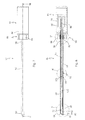
- Fig. 1 is an endoscope provided with the general reference numeral 10, in particular a medical video endoscope.
- the endoscope 10 generally includes an elongate shaft 12 and a head 14 having a housing 16 at a proximal end 18 of the shaft 12.
- a distal end of the shaft 12 is denoted by reference numeral 20 in FIG Fig. 1 Mistake.
- a light source 22 is arranged, which is preferably designed as a high-performance light-emitting diode (LED or OLED). In operation, the light source 22 generates heat loss.
- LED light-emitting diode
- the endoscope 10 has a passive cooling, a in Having the shaft 12 disposed heat pipe 24 in the form of a heat pipe.
- the heat pipe 24 has a distal end 26 which is thermally coupled to the light source 22.
- the thermal coupling is via a heat coupling element 28, which is made as a solid body of a good heat conductive material, such as copper or aluminum.
- the heat coupling element 28 has a sleeve-like extension 30, as in Fig. 4 is shown, which receives the distal end 26 of the heat pipe 24 free of air gap, to provide a particularly good heat transfer from the heat coupling element 28 to the heat pipe 24.
- the heat coupling element 28 is in turn connected in a heat-conducting manner with the rear side of the light source 22.
- the heat pipe 24 extends according to Fig. 2 through the shaft 12 through into the head piece 14, ie it protrudes into the housing 16 of the head piece 14 inside.
- a heat sink body 32 is arranged, with which the heat pipe 24 is thermally coupled.
- a proximal end 34 of the heat pipe 24 is connected to the heat sink body 32 in an inner sleeve 36 of the heat sink body 32 with this heat-conducting.
- the heat sink body 32 in turn is heat-conductively connected to the housing 16 so that the heat sink body 32 can transfer the heat received from the heat pipe 24 to the housing 16 of the header 14, and the heat is then radiated from the head 14 to the environment.
- the heat sink body 32 is tubular or rod-shaped and formed on the outer circumference over a large area, as well as the head 14 is formed over a large area.
- the outer diameter of the heat sink body 32 and the housing 16 of the head piece are larger than the outer diameter of the shaft 12.
- the heat sink body 32 may also be part of the housing 16 itself and then release the absorbed heat directly to the environment.
- the head 14 In use of the endoscope 10 in a surgical procedure, the head 14 is located outside the human or animal body, so that the heat radiation via the head 14 to the environment is harmless. In contrast, the shaft 12 remains outside on the outside, at least in the area which is introduced during the surgical procedure in the human or animal body, below the maximum allowable temperature.
- the heat loss from the heat sink body 32 is also transmitted to the housing 16.
- the heat pipe 24 is furthermore at least in the region of the distal end 20, preferably up to the head piece 14, against the inside of the shaft 12 thermally insulated. This can be realized by an insulating jacket of the heat pipe 24 itself or by an insulation on the inside of the shaft 12, as will be described later with reference to a further embodiment.
- the endoscope 10 furthermore has a camera 42 which, for example, has a CCD or CMOS-based image sensor 43 which is arranged in the distal region of the shaft 12.
- the image sensor 43 is upstream of the light inlet side, a lens 44.
- an electrical line 46 and for the image sensor 43 an electrical line 48 is provided which extend from the light source 22 and from the image sensor 43 to the head piece 14, as in Fig. 2 and 5 is shown.
- the electrical leads 46 and 48 lead to corresponding electrical terminals (not shown) at the proximal end of the header 14.
- the heat pipe 24 is designed in the form of a heat pipe.
- the heat transfer medium evaporated by the light source 22 received heat loss at the distal end and condenses again at the proximal end 34 of the heat pipe 24, from where it returns to the distal end due to the capillary action.
- the heat transfer medium thus stores heat in the form of latent heat, which is transported proximally and released there again in the form of latent heat.
- the heat transfer capability of a heat pipe is higher by a factor of Z times than the heat transport capability of, for example, a copper wire.
- the endoscope 50 is in particular a medical video endoscope.
- the endoscope 50 generally has a shaft 52 and a head 54 with a housing 56.
- the headpiece 54 is disposed at a proximal end 58 of the shaft 52.
- a distal end of the shaft 52 is provided with the reference numeral 60.
- a first light source 62 and a second light source 64 are arranged in the distal region of the shaft 52.
- the light sources 62 and 64 are formed as LEDs or OLEDs.
- the light sources 62 and 64 generate waste heat in operation, as already described with reference to the previous embodiment.
- the endoscope 50 has a first heat pipe 66 which is thermally coupled to the light sources 62 and 64, and another heat pipe 68 connected to the light sources 62 and 64 is thermally coupled.
- a heat coupling element 70 is provided, are inserted from the proximal end of the distal ends of the heat pipes 66 and 68 possible free of air gap, wherein the heat coupling element 70 in turn with the light sources 62 and 64 is thermally conductively connected.
- the heat coupling element 70 is in turn formed here as a solid, which is made of a good thermal conductivity material, such as copper or aluminum.
- the heat pipes 66 and 68 are each formed as a heat pipe.
- the first heat pipe 66 and the further heat pipe 68 extend into an intermediate region 72 (cf. Fig. 8 . 9 and 11 ) located between the distal end 60 and the proximal end 58 of the shaft 52. It is not necessary that the intermediate portion 72 is located midway between the distal end 60 and the proximal end 58, but may be located at locations other than illustrated.
- the first heat pipe 66 and the further heat pipe 68 are thermally coupled to a second heat pipe 74.
- a further heat coupling element 76 is arranged in the intermediate region 72, which is thermally conductively connected both to the proximal ends of the first heat pipe 66 and the further heat pipe 68, as well as with the distal end of the second heat pipe 74.
- the heat coupling element 76 surrounds the proximal ends of the Heat pipes 66 and 68 on the one hand and the distal end of the second heat pipe 74 on the other. In this way, in turn, a good heat transfer from the heat pipes 66 and 68 is ensured on the second heat pipe 74.
- the heat coupling element 76 itself is flexible, so that the cascaded arrangement of the heat pipes 66, 68 on the one hand and the second heat pipe 74 on the other hand in the intermediate region 72 has a certain flexibility, so that the shaft 52 of the endoscope 50 in particular semi-flexible can be configured.
- the second heat pipe 74 now extends into the head piece 54 in which it is thermally coupled to a heat sink body 78, reference being made to the description of the heat sink body 32 of the previous embodiment with respect to the thermal coupling and the configuration of the heat sink body 78, wherein in the heat sink body 78 may be arranged in turn electronic and / or electrical components.
- the endoscope 50 further has a camera 80 arranged in the distal region of the shaft 52, which has, for example, an image sensor 81 in CCD or CMOS design. On the distal side of the image sensor 81, the camera 80 has an objective 82.
- the objective 82 also has an oblique viewing optics 84, so that the viewing direction of the endoscope 50 with the longitudinal axis of the shaft 52 encloses an angle of # 0 °, for example 30 °.
- the oblique view optics 84 may also be integrated into the objective 82.
- the shaft 52 By turning the shaft 52 about its longitudinal axis allows the endoscope 50 with the same orientation of the longitudinal axis of the shaft 52 different Viewing directions of the endoscope 50 in the observed area.
- the camera 80 here only the image sensor 81 of the camera 80, relative to the shaft 52 about the optical axis of the camera 80 is rotatable.
- a rotary drive 86 corresponding to the head piece 54 is provided, which is designed in the form of a magnetic coupling.
- the rotary drive 86 has an outside on the shaft 52 at the proximal end 58 arranged driving actuator 88, which is designed as a handwheel.
- the adjusting element 88 has a plurality of magnets 90 on its inner circumference. In Fig. 12 the magnetic poles are illustrated with N and S.
- the rotary drive 86 furthermore has a driven element 92 which cooperates magnetically with the adjusting element 88 and which likewise has a plurality of magnets 94 (cf. Fig. 9 ), whose poles in Fig. 12 also illustrated with N and S. Due to the magnetic frictional connection between the magnets 90 of the actuating element 88 and the magnet 94 of the driven element 92, the driven element 92 follows a rotational movement of the actuating element 88 in the same direction of rotation.
- the second heat pipe 74 is rotatably coupled to the driven member 92, passed therethrough, so that rotation of the driven member 92 about its longitudinal axis causes rotation of the second heat pipe 74 in the same rotational direction.
- the second heat pipe 74 is also rotatably received in the shaft relative to the shaft 52 about its longitudinal axis.
- the second heat pipe 74 is thus used in this embodiment not only for heat transfer of the heat loss of the light sources 62 and 64 in the head piece 54, but also as a torque transmission element for the camera 80th
- the second heat pipe 74 is surrounded by a tube 96, which is made for example of copper or aluminum, generally of a thermally highly conductive material.
- the second heat pipe 74 is rotatably mounted in the intermediate region 72 in the heat coupling element 76, while the heat coupling element 76 itself is rotationally fixed as the first heat pipe 66 and the second heat pipe 68 and the light sources 62 and 64 is held.
- the rotatable mounting of the second heat pipe 74 in the heat coupling element 76 is realized so that, furthermore, a good heat transfer from the heat pipes 66 and 68 to the second heat pipe 74 is ensured.
- a proximal end 98 of the second heat pipe 74 is also rotatably supported in the heat sink body 78 in the header 54.
- a torque transmitting element 102 which is designed here as a flexible shaft, which is particularly advantageous if the axis of rotation of the camera 80 is not aligned with the longitudinal axis of the second heat pipe 74, as in particular Fig. 8 evident.
- the torque transmission element 102 is in this case rotatably coupled to a distal end 103 of the tube 96.
- the shaft 52 In order to change the viewing direction in the endoscope 50, the shaft 52 is rotated about its longitudinal axis, and thereby not to change the orientation of the camera 80, the actuator 88 is held, whereby on the driven member 92 corresponding to the second heat pipe 74 and the torque transmitting element 102 the camera 80 is also held, whereby the camera 80 is prevented from rotating about its own optical axis so that the shaft 52 rotates around the camera 80.
- the stem 52 is thermally insulated from the heat pipes 66, 68 and 74.
- the shaft 52 is provided on the inside with a thermal insulation 104 which is formed in the form of an intermediate tube made of a thermally insulating material.
- the thermal insulation 104 extends from the distal end of the shaft 52 to the proximal end of the shaft, which partially projects into the header 54, as in FIG Fig. 8 and 12 is shown.
- the heat pipes 66, 68 and 74 on the outside with a thermal insulation (not shown) to be wrapped.
- the light source 64 may be provided, in which case only the heat pipe 68 is thermally coupled in the intermediate region 72 with the second heat pipe 74, while the rest of the configuration, in particular the rotatability of the second heat pipe 74 is maintained relative to the shaft 52.
- the endoscope 50 may also have more than the two light sources 62 and 64 and also a larger number of heat pipes 66, 68, however, given the possibly very small diameter of the shaft 52, a number of two heat pipes 66, 68 at two light sources 62 and 64 is advantageous.
- the heat pipe cascade of the first heat pipe 66, further heat pipe 68 and second heat pipe 74 instead of two-stage as well as three, four, etc. stages can be formed.
Abstract
Description
Die Erfindung betrifft ein Endoskop, mit einem langerstreckten Schaft, mit einem Kopfstück an einem proximalen Ende des Schafts, wobei das Kopfstück ein Gehäuse aufweist, mit zumindest einer in dem Schaft in einem distalen Bereich desselben angeordneten Lichtquelle, die Verlustwärme erzeugt, und mit einer passiven Kühlung, die zumindest ein in dem Schaft angeordnetes Wärmerohr in Form einer Heatpipe aufweist, die mit der zumindest einen Lichtquelle thermisch gekoppelt ist, um die Verlustwärme in Richtung nach proximal abzuführen.The invention relates to an endoscope, comprising an elongate shaft, with a head piece at a proximal end of the shaft, the head piece having a housing, with at least one light source in the shaft, which generates waste heat in a shaft in a distal region, and with a passive one Cooling, which has at least one arranged in the shaft heat pipe in the form of a heat pipe, which is thermally coupled to the at least one light source to dissipate the heat loss in the proximal direction.
Ein solches Endoskop ist aus dem Dokument
Das in dem vorstehend genannten Dokument beschriebene Endoskop ist ein technisches Endoskop, das zur Untersuchung von Maschinen, insbesondere Flugzeugtriebwerken, verwendet wird.The endoscope described in the above document is a technical endoscope used to inspect machines, particularly aircraft engines.
Die vorliegende Erfindung betrifft insbesondere ein medizinisches Endoskop, das im Rahmen der minimal-invasiven Chirurgie als Beobachtungsinstrument verwendet wird. Bei einem solchen medizinischen Endoskop wird der langerstreckte Schaft durch eine künstlich geschaffene oder natürliche Öffnung teilweise in den Körper eingeführt.In particular, the present invention relates to a medical endoscope that is used as a monitoring instrument in minimally invasive surgery. In such a medical endoscope, the elongated shaft is partially inserted into the body through an artificially created or natural opening.
Heutzutage weisen Endoskope eine oder mehrere in den Endoskopschaft integrierte Lichtquellen auf, die als Leuchtdioden (LED) ausgebildet sind. Durch die Integration einer oder mehrerer Lichtquellen in den Schaft des Endoskops, üblicherweise im distalen Bereich des Schafts, kann auf eine externe Lichtquelle, beispielsweise eine Xenon-Lampe, verzichtet werden. Der Vorteil einer oder mehrerer in den Schaft des Endoskops integrierter Lichtquellen besteht darin, dass das bei Verwendung einer externen Lichtquelle erforderliche Lichtleitkabel wegfällt, wodurch die Ergonomie des Endoskops verbessert ist. Durch den Wegfall externer Lichtquellen und Lichtleitkabel werden außerdem die Herstellungs- und Anschaffungskosten von Endoskopen reduziert.Nowadays, endoscopes have one or more light sources integrated in the endoscope shaft, which are designed as light-emitting diodes (LEDs). By integrating one or more light sources into the shaft of the endoscope, usually in the distal region of the shaft, it is possible to dispense with an external light source, for example a xenon lamp. The advantage of one or more light sources integrated in the shaft of the endoscope is that the optical fiber cable required when using an external light source is eliminated, which improves the ergonomics of the endoscope. The elimination of external light sources and fiber optic cables also reduces the manufacturing and acquisition costs of endoscopes.
Bei einem Endoskop, das eine in den Schaft integrierte Lichtquelle aufweist, ergibt sich jedoch das technische Problem, dass die Lichtquelle im Betrieb an ihrem Ort Verlustwärme in dem Schaft erzeugt, die den Schaft mitunter stark erwärmt, insbesondere im Bereich des distalen Endes des Schafts, wo die Lichtquelle(n) angeordnet ist (sind).In an endoscope having a light source integrated in the shaft, however, there is the technical problem that the light source generates in operation loss of heat in the shaft, which sometimes heats the shaft strongly, in particular in the region of the distal end of the shaft, where the light source (s) is (are) located.
Ein Endoskop, das in der Chirurgie verwendet wird, unterliegt Vorschriften des Medizinproduktgesetzes. Gemäß dem Medizinproduktgesetz darf der Endoskopschaft außenseitig eine Temperatur von 41°C nicht überschreiten, um eine wärmebedingte Beschädigung von Gewebe im menschlichen oder tierischen Körper zu vermeiden.An endoscope that is used in surgery is subject to regulations of the Medical Devices Act. According to the Medical Devices Act, the endoscope shaft on the outside must not exceed a temperature of 41 ° C to a to avoid heat damage to tissue in the human or animal body.
Heutige Hochleistungs-LEDs erzeugen jedoch so viel Verlustwärme, dass sich der Schaft über die geforderte Maximaltemperatur von 41°C hinaus rasch erwärmen würde. Vor diesem Hintergrund ist es erforderlich, in dem Schaft eine Kühlung vorzusehen, die die Verlustwärme so abführt, dass sich der Schaft nicht über die gesetzlich vorgeschriebene Maximaltemperatur hinaus erwärmt.However, today's high-power LEDs generate so much heat loss that the shaft would heat up quickly beyond the required maximum temperature of 41 ° C. Against this background, it is necessary to provide a cooling in the shaft, which dissipates the heat loss so that the shaft does not heat beyond the legally prescribed maximum temperature.
Zur Kühlung bzw. Abfuhr der Verlustwärme sind verschiedene Konzepte bekannt.To cool or dissipate the heat loss various concepts are known.
Bei dem aus dem eingangs genannten Dokument bekannten Endoskop ist zur Abfuhr der Verlustwärme von der im distalen Bereich des Schafts angeordneten Lichtquelle, die dort als LED ausgebildet ist, ein Wärmerohr in Form einer Heatpipe vorhanden, dessen distales Ende mit der Lichtquelle thermisch leitend gekoppelt ist. Ein solches Wärmerohr ist ein Wärmeüberträger, der unter Nutzung von Verdampfungswärme eines Stoffes, der in dem Wärmerohr enthalten ist, eine hohe Wärmestromdichte erlaubt, d.h. auf kleiner Querschnittsfläche können große Mengen Wärme transportiert werden. Zur Umwälzung des als Wärmetransportmedium in dem Wärmerohr vorhandenen Stoffes wird keine zusätzliche Hilfsenergie wie beispielsweise eine Umwälzpumpe benötigt, wodurch sich der Wartungsaufwand und die Betriebskosten eines solchen Wärmerohrs minimieren.In the endoscope known from the document mentioned above, a heat pipe in the form of a heat pipe is provided for dissipating the heat loss from the arranged in the distal region of the shaft light source, which is designed there as a LED, whose distal end is thermally conductively coupled to the light source. Such a heat pipe is a heat exchanger that allows high heat flux density by utilizing the heat of vaporization of a substance contained in the heat pipe, i. On small cross-sectional area, large amounts of heat can be transported. To circulate the substance present as a heat transport medium in the heat pipe no additional auxiliary energy such as a circulating pump is required, thereby minimizing the maintenance and operating costs of such a heat pipe.
Eine spezielle Art eines Wärmerohrs ist die sogenannte Heatpipe. Bei einer Heatpipe verdampft das Wärmeträgermedium am "warmen" Ende des Wärmerohrs, wobei der Dampf zum "kalten" Ende geleitet wird, wo der Dampf wieder kondensiert. Bei der Wärmeabfuhr wird somit latente Wärme genutzt, wodurch die Wärmeleitung in einer Heatpipe gegenüber einer Wärmeleitung in beispielsweise Kupfer um das Zig-fache größer ist. In der Heatpipe wird Flüssigkeit, die als Wärmetransportmedium dient, mittels Kapillaren nach dem Dochtprinzip zum Verdampfungsende zurückgeführt. Das kondensierte Fluid fließt daher lageunabhängig in der Kapillare zurück zum Verdampfungsende des Wärmerohrs, d.h. dem mit der Lichtquelle gekoppelten Ende des Wärmerohrs. Aufgrund der Ausnutzung des Kapillarprinzips arbeiten Heatpipes daher unter beliebigen Orientierungen zur Schwerkraft.A special type of heat pipe is the so-called heat pipe. In a heat pipe, the heat transfer medium vaporizes at the "warm" end of the heat pipe, with the steam going to the "cold" end where the steam condenses again. In the heat dissipation thus latent heat is used, whereby the heat conduction in a heat pipe compared to a heat conduction in, for example, copper is larger by a factor of tens. In the heat pipe, liquid, which serves as a heat transport medium, by means of capillaries after the wicking principle to the end of evaporation recycled. The condensed fluid therefore flows independently of position in the capillary back to the end of evaporation of the heat pipe, ie the end of the heat pipe coupled to the light source. Due to the utilization of the capillary principle, heatpipes therefore work under any orientation to gravity.
Bei dem vorstehend genannten bekannten Endoskop erstreckt sich das Wärmerohr über eine kleine Länge des Schafts des Endoskops nach proximal, und mit dem proximalen Ende des Wärmerohrs ist ein wärmeleitfähiger Draht, beispielsweise ein Kupferdraht verbunden, wobei der Draht sich weiter nach proximal erstreckt und mit seinem proximalen Ende mit der Innenseite des Schaftes des Endoskops wärmeleitend verbunden ist.In the aforementioned known endoscope, the heat pipe extends proximally over a small length of the shaft of the endoscope, and connected to the proximal end of the heat pipe is a thermally conductive wire such as a copper wire, the wire extending further proximally and with its proximal end End is thermally conductively connected to the inside of the shaft of the endoscope.
Diese Art der Kühlung ist für ein medizinisches Endoskop jedoch unzureichend, da die Wärme von dem Wärmerohr auf den Schaft des Endoskops übertragen wird, wodurch sich der Schaft erwärmt, was jedoch bei einem medizinischen Endoskop gerade vermieden werden soll.However, this type of cooling is inadequate for a medical endoscope because the heat is transferred from the heat pipe to the shaft of the endoscope, whereby the shaft heats up, which is just to be avoided in a medical endoscope.
Aus
Aus
Weitere Endoskope, bei denen die Kühlung der im Schaft angeordneten Lichtquelle mittels eines externen Kühlkreislaufes bewerkstelligt wird, sind aus
Bei den vorstehend genannten bekannten Kühlkonzepten erfolgt die Kühlung des Endoskopschafts somit mittels eines externen Kühlkreislaufes, wobei ein Kühlmedium, beispielsweise ein gasförmiges oder flüssiges Kühlmedium, durch den Schaft geleitet wird.In the aforementioned known cooling concepts, the cooling of the endoscope shaft is thus effected by means of an external cooling circuit, wherein a cooling medium, for example a gaseous or liquid cooling medium, is passed through the shaft.
Der Nachteil eines solchen Kühlkonzepts besteht jedoch darin, dass für den Kühlkreislauf beispielsweise externe Kühlleitungen, Umwälzpumpen und ein Reservoir für das Kühlmedium erforderlich sind, was zum einen den Herstellungs-und Kostenaufwand eines derartigen Endoskops erhöht, und zum anderen auch die Ergonomie des Endoskops beeinträchtigt, weil das Endoskop mit externen Kühlleitungen des Kühlkreislaufes verbunden werden muss, die bei der Handhabung des Endoskops in einem chirurgischen Eingriff störend wirken.However, the disadvantage of such a cooling concept is that, for example, external cooling lines, circulating pumps and a reservoir for the cooling medium are required for the cooling circuit, which on the one hand increases the production and cost of such an endoscope and, on the other hand, also impairs the ergonomics of the endoscope, because the endoscope must be connected to external cooling lines of the cooling circuit, which interfere with the handling of the endoscope in a surgical procedure.
Es ist daher eine Aufgabe der vorliegenden Erfindung, ein Endoskop der eingangs genannten Art dahingehend weiterzubilden, dass mit geringem Herstellungs- und Kostenaufwand eine zuverlässige Abfuhr der Verlustwärme von der zumindest einen im Schaft des Endoskops angeordneten Lichtquelle erreicht wird.It is therefore an object of the present invention to develop an endoscope of the type mentioned in that with low manufacturing and cost reliable dissipation of the heat loss is achieved by at least one arranged in the shaft of the endoscope light source.
Erfindungsgemäß wird diese Aufgabe hinsichtlich des eingangs genannten Endoskops dadurch gelöst, dass sich das zumindest eine Wärmerohr bis in das Kopfstück erstreckt, und dass in dem Kopfstück ein Wärmesenkekörper angeordnet ist, mit dem das zumindest eine Wärmerohr thermisch gekoppelt ist, und der die Verlustwärme von dem zumindest einen Wärmerohr aufnimmt und direkt oder über das Gehäuse des Kopfstücks an die Umgebung abgibt.According to the invention, this object is achieved with respect to the endoscope mentioned above in that the at least one heat pipe extends into the head piece, and that in the head piece a heat sink body is arranged, with which the at least one heat pipe is thermally coupled, and the heat loss from the at least one heat pipe receives and delivers directly or through the housing of the head piece to the environment.
Das erfindungsgemäße Endoskop nutzt somit für die Abfuhr der von der zumindest einen Lichtquelle im distalen Bereich des Schafts erzeugte Verlustwärme die Vorteile einer Heatpipe, wodurch ein Kühlkreislauf und damit Anschlüsse für die Zufuhr eines Kühlmediums und Anschlüsse für die Abfuhr eines Kühlmediums und externe Kühlleitungen vermieden werden. Dadurch, dass sich das zumindest eine Wärmerohr bis in das Kopfstück erstreckt, in dem ein Wärmesenkekörper angeordnet ist, wird die Verlustwärme mit hoher Übertragungsrate bis zum Kopfstück transportiert, wo die Wärme an das großflächige Gehäuse des Kopfstückes, also an eine große Fläche und über diese oder direkt an die Umgebung abgegeben wird. Im letzteren Fall kann der Wärmesenkekörper selbst ein Teil des Gehäuses des Kopfstücks sein. Da das Kopfstück bei einem medizinischen Endoskop während eines chirurgischen Eingriffs außerhalb des menschlichen oder tierischen Körpers angeordnet ist, führt die Wärmeabgabe über das Kopfstück an die Umgebung nicht zu einer wärmebedingten Schädigung von Gewebe innerhalb des menschlichen oder tierischen Körpers. Der Schaft des Endoskops wird bei dem erfindungsgemäßen Endoskop somit hinreichend gegen eine Erwärmung geschützt, so dass das erfindungsgemäße Endoskop den gesetzlichen Anforderungen an die Maximaltemperatur des Schafts erfüllt. Das im Verhältnis zum Endoskopschaft großflächigere Kopfstück ist in der Lage, die Wärme vom Wärmekörper, der ebenfalls großflächig ist, gut aufzunehmen und an die Umgebung abzugeben. Durch die Bauweise des erfindungsgemäßen Endoskops mit einem Wärmerohr zur Abfuhr der von der zumindest einen Lichtquelle erzeugten Verlustwärme ist das Endoskop insgesamt sehr kostengünstig und auf konstruktiv einfache Weise herstellbar, wodurch sich das erfindungsgemäße Endoskop auch als Einwegendoskop eignen kann.The endoscope according to the invention thus utilizes the advantages of a heat pipe for the removal of the heat loss generated by the at least one light source in the distal region of the shaft, whereby a cooling circuit and thus connections for the supply of a cooling medium and connections for the removal of a cooling medium and external cooling lines are avoided. Characterized in that the at least one heat pipe extends into the head piece, in which a heat sink body is arranged, the heat loss is transported at a high transfer rate to the head, where the heat is delivered to the large housing of the head piece, ie a large area and on this or directly to the environment. In the latter case, the heat sink body itself may be part of the housing of the header. Since the headpiece is located outside of the human or animal body in a medical endoscope during a surgical procedure, the heat release via the head piece to the environment does not lead to a heat-related damage to tissue within the human or animal body. The shaft of the endoscope is thus sufficiently protected in the endoscope according to the invention against heating, so that the endoscope according to the invention meets the legal requirements for the maximum temperature of the shaft. The relatively large headspace in relation to the endoscope shaft is able to absorb the heat from the heat body, which is also large, well and to deliver it to the environment. Due to the design of the endoscope according to the invention with a heat pipe to dissipate the loss of heat generated by the at least one light source, the endoscope is overall very inexpensive and can be produced in a structurally simple manner, whereby the endoscope according to the invention can also be suitable as a disposable endoscope.
In einer bevorzugten Ausgestaltung ist der Schaft zumindest im Bereich seines distalen Endes innenseitig gegen das zumindest eine Wärmerohr thermisch isoliert.In a preferred embodiment, the shaft is thermally insulated at least in the region of its distal end against the at least one heat pipe.
Da sich das Wärmerohr durch die von der zumindest einen Lichtquelle aufgenommene Verlustwärme selbst erwärmt und diese Wärme zwar nach proximal abführt, wird durch die vorstehend genannte Maßnahme vorteilhafterweise vermieden, dass das Wärmerohr Wärme an den Schaft abstrahlt und dadurch der Schaft über das zulässige Maß erwärmt wird.Since the heat pipe itself heats up by the loss heat absorbed by the at least one light source and indeed dissipates this heat proximally, it is advantageously avoided by the above-mentioned measure that the heat pipe radiates heat to the shaft and thereby heats the shaft beyond the permissible level ,
In dieser Ausgestaltung kann die Isolation dadurch realisiert sein, dass das Wärmerohr außenseitig mit einer Isolierung, beispielsweise einer wärmedämmenden Beschichtung versehen ist, und/oder dass der Schaft innenseitig mit einer Isolierung versehen ist, d.h. an der Innenwand des Schafts eine wärmedämmende Beschichtung aufweist, und/oder dass ein wärmedämmendes Isolierrohr zwischen der Schaftinnenwand und der Außenwand des zumindest einen Wärmerohrs angeordnet ist.In this embodiment, the insulation can be realized in that the heat pipe on the outside with an insulation, such as a heat-insulating Is provided coating, and / or that the shaft is provided on the inside with an insulation, ie, on the inner wall of the shaft has a heat-insulating coating, and / or that a heat insulating insulating tube between the shaft inner wall and the outer wall of the at least one heat pipe is arranged.
In einer weiteren bevorzugten Ausgestaltung sind elektronische und/oder elektrische Bauelemente in einem Hohlraum des Wärmesenkekörpers angeordnet.In a further preferred embodiment, electronic and / or electrical components are arranged in a cavity of the heat sink body.
Hierbei ist von Vorteil, dass der Wärmesenkekörper im Kopfstück des Endoskops nicht nur die vom Wärmerohr abgegebene Wärme an das Kopfstück abgibt, sondern auch die von den elektronischen oder elektrischen Bauelementen erzeugte Verlustwärme. Solche elektronischen oder elektrischen Bauelemente sind bei dem Endoskop insbesondere dann vorgesehen, wenn das Endoskop ein Videoendoskop mit einer Kamera im distalen Bereich des Schafts oder im Kopfstück ist.It is advantageous that the heat sink body in the head of the endoscope not only emits the heat emitted by the heat pipe to the head, but also the loss of heat generated by the electronic or electrical components. Such electronic or electrical components are provided in the endoscope in particular when the endoscope is a video endoscope with a camera in the distal region of the shaft or in the head piece.
In einer weiteren bevorzugten Ausgestaltung ist ein distales Ende des zumindest einen Wärmerohrs mit der zumindest einen Lichtquelle mittels eines Wärmekoppelelements thermisch leitend verbunden.In a further preferred refinement, a distal end of the at least one heat pipe is connected in a thermally conductive manner to the at least one light source by means of a heat coupling element.
Gegenüber einer thermischen Kopplung der zumindest einen Lichtquelle mit dem zumindest einen Wärmerohr über Wärmestrahlung hat diese Maßnahme den Vorteil, dass die Wärmeübertragung von der zumindest einen Lichtquelle auf das zumindest eine Wärmerohr durch Wärmeleitung weiter verbessert ist. Ein Wärmekoppelelement kann hier ein Festkörper sein, dessen Material über eine hohe Wärmeleitfähigkeit verfügt, beispielsweise Kupfer oder Aluminium. Das Wärmekoppelelement steht dabei vorzugsweise über eine möglichst große Fläche mit der zumindest einen Lichtquelle und dem zumindest einen Wärmerohr berührend in Verbindung, ohne dass Luftspalte an diesen Berührflächen vorhanden sind, was durch Lötung, Kleben oder dergleichen bewerkstelligt sein kann.Compared with a thermal coupling of the at least one light source with the at least one heat pipe via thermal radiation, this measure has the advantage that the heat transfer from the at least one light source to the at least one heat pipe is further improved by heat conduction. A heat coupling element here can be a solid whose material has a high thermal conductivity, for example copper or aluminum. The heat coupling element is preferably in contact over the largest possible area with the at least one light source and the at least one heat pipe in contact without air gaps are present at these contact surfaces, which can be accomplished by soldering, gluing or the like.
In einer weiteren bevorzugten Ausgestaltung umgibt der Wärmesenkekörper einen proximalen Endbereich des zumindest einen Wärmerohrs und steht mit diesem unmittelbar in Berührung.In a further preferred embodiment, the heat sink body surrounds a proximal end region of the at least one heat pipe and is in direct contact therewith.
Durch diese Maßnahme werden, wie bei der Wärmeübertragung von der zumindest einen Lichtquelle auf das zumindest eine Wärmerohr mittels des zuvor genannten Wärmekoppelelements, die vorstehend genannten Vorteile einer sehr guten Wärmeübertragung auch vom proximalen Endbereich des zumindest einen Wärmerohrs auf den Wärmesenkekörper erreicht.As a result of this measure, as with the heat transfer from the at least one light source to the at least one heat pipe by means of the aforementioned heat coupling element, the above-mentioned advantages of a very good heat transfer also reach the heat sink body from the proximal end region of the at least one heat pipe.
In einer weiteren bevorzugten Ausgestaltung weist das zumindest eine Wärmerohr ein erstes Wärmerohr, das mit der zumindest einen Lichtquelle gekoppelt ist und sich bis zu einem Zwischenbereich im Schaft zwischen dem distalen und proximalen Ende desselben erstreckt, und zumindest ein zweites Wärmerohr in Form einer Heatpipe auf, das mit dem ersten Wärmerohr thermisch gekoppelt, und das sich von dem Zwischenbereich bis in das Kopfstück erstreckt und mit dem Wärmesenkekörper thermisch gekoppelt ist.In a further preferred embodiment, the at least one heat pipe has a first heat pipe, which is coupled to the at least one light source and extends to an intermediate region in the shaft between the distal and proximal ends thereof, and at least one second heat pipe in the form of a heat pipe, thermally coupled to the first heat pipe and extending from the intermediate region into the header and thermally coupled to the heat sink body.
Diese Maßnahme hat zum einen den Vorteil, dass über eine Kaskade von Wärmerohren auch Endoskope mit sehr langen Schäften mit dem erfindungsgemäßen Kühlkonzept versehen werden können. Zum anderen hat diese Maßnahme den Vorteil, dass auch Endoskope mit semi-flexiblen Schäften mit dem erfindungsgemäßen Kühlkonzept ausgestattet werden können, indem mehrere Wärmerohre in Form von Heatpipes, die jeweils für sich nur eine geringere Länge als der Schaft aufweisen, durch die Hintereinanderschaltung eine nicht-starre Anordnung ergeben.This measure has the advantage that a cascade of heat pipes and endoscopes with very long shafts can be provided with the cooling concept of the invention on the one hand. On the other hand, this measure has the advantage that even endoscopes with semi-flexible shafts can be equipped with the cooling concept of the invention by several heat pipes in the form of heat pipes, each of which only has a smaller length than the shaft, by the series connection one not rigid arrangement result.
In diesem Zusammenhang ist es weiterhin bevorzugt, wenn sich das erste Wärmerohr und das zumindest eine zweite Wärmerohr in dem Zwischenbereich in Längsrichtung des Schafts teilweise überlappen.In this context, it is further preferred if the first heat pipe and the at least one second heat pipe partially overlap in the intermediate region in the longitudinal direction of the shaft.
Diese Maßnahme trägt vorteilhafterweise zu einer verbesserten Wärmeübertragung zwischen den einzelnen Wärmerohren und damit zu einer besseren Abfuhr der Verlustwärme in das Kopfstück des Endoskops bei.This measure advantageously contributes to an improved heat transfer between the individual heat pipes and thus to a better removal of the heat loss in the head piece of the endoscope.
In einer weiteren bevorzugten Ausgestaltung sind das erste Wärmerohr und das zumindest eine zweite Wärmerohr in dem Zwischenbereich mittels eines Wärmekoppelelements miteinander thermisch leitend verbunden, das das erste und das zumindest eine zweite Wärmerohr umgibt.In a further preferred refinement, the first heat pipe and the at least one second heat pipe are thermally conductively connected to one another in the intermediate region by means of a heat coupling element which surrounds the first and the at least one second heat pipe.
Durch diese Maßnahme wird die Wärmeübertragung in Wärmetransportrichtung noch weiter verbessert, insbesondere wenn das Wärmekoppelelement wie in einer vergleichbaren Ausgestaltung oben bereits angegeben aus einem Material besteht, das sehr gut wärmeleitend ist, beispielsweise aus Kupfer oder Aluminium.By this measure, the heat transfer in the heat transport direction is further improved, in particular if the heat coupling element as already stated in a comparable embodiment above consists of a material which is very good thermal conductivity, for example of copper or aluminum.
Bei den zuvor genannten Ausgestaltungen gibt das "kalte" Ende des jeweils distalseitigen Wärmerohrs die Verlustwärme an das "warme" Ende des sich jeweils anschließenden Wärmerohrs ab, das dann die Verlustwärme weiter nach proximal transportiert.In the aforementioned embodiments, the "cold" end of each distal-side heat pipe releases the heat loss to the "warm" end of each adjacent heat pipe, which then transports the heat loss further to the proximal.
In einer weiteren bevorzugten Ausgestaltung der vorstehend genannten Maßnahmen ist das Wärmekoppelelement flexibel.In a further preferred embodiment of the aforementioned measures, the heat coupling element is flexible.
Hierbei ist von Vorteil, dass eine "Gelenkigkeit" der Kaskadenanordnung der einzelnen Wärmerohre bei gleichzeitig sehr guter Wärmeübertragung zwischen den einzelnen Wärmerohren erreicht wird, so dass sich diese Ausgestaltung insbesondere für Endoskope mit semi-flexiblen Schäften eignet. Ein solches flexibles Wärmekoppelelement kann beispielsweise in Form eines oder mehrerer flexibler Drähte, die beispielsweise aus Kupfer gefertigt sind, ausgeführt sein.It is advantageous that a "flexibility" of the cascade arrangement of the individual heat pipes is achieved at the same time very good heat transfer between the individual heat pipes, so that this configuration is particularly suitable for endoscopes with semi-flexible shafts. Such a flexible heat coupling element may, for example, in the form of one or more flexible wires, which are made of copper, for example.
In einer noch weiteren bevorzugten Ausgestaltung der vorstehend genannten Maßnahmen ist das zumindest eine zweite Wärmerohr relativ zum Schaft um eine Längsachse des zumindest einen zweiten Wärmerohrs drehbar, wobei das zumindest eine zweite Wärmerohr einerseits mit einer am distalen Bereich des Schafts angeordneten Kamera verbunden und andererseits mit einem Drehantrieb verbunden ist, um eine Drehung der Kamera um ihre optische Achse relativ zum Schaft zu ermöglichen.In yet another preferred embodiment of the above-mentioned measures, the at least one second heat pipe is rotatable relative to the shaft about a longitudinal axis of the at least one second heat pipe, wherein the at least one second heat pipe is connected on the one hand to a camera arranged on the distal region of the shaft and on the other hand to a second heat pipe Rotary drive is connected to allow rotation of the camera about its optical axis relative to the shaft.
In dieser Ausgestaltung ist das Endoskop ein Videoendoskop, das eine im distalen Bereich des Schafts angeordnete Kamera aufweist. Insbesondere bei Videoendoskopen mit einer sogenannten Schrägblickoptik, bei der die Blickrichtung durch das Endoskop schräg zur Längsachse des Schafts des Endoskops gerichtet ist, ist es üblicherweise vorgesehen, dass der Schaft und die Kamera relativ zueinander verdrehbar sind. Hintergrund dieser relativen Verdrehbarkeit ist, dass zur Änderung der Blickrichtung der Schaft um die eigene Längsachse gedreht wird. Um dabei den Horizont des von der Kamera aufgenommenen Bildes nicht zu verdrehen, weil andernfalls der das Endoskop bedienende Arzt seine Orientierung im Beobachtungsgebiet verlieren könnte, ist die Kamera daher relativ zum Schaft drehbar, so dass durch relative Drehung der Kamera zum Schaft das wahrgenommene Bild stets aufrecht gehalten werden kann. Die Kamera weist beispielsweise einen Bildsensor und ein diesem vorgeordnetes Objektiv auf. Soweit in der vorliegenden Anmeldung beschrieben ist, dass die Kamera drehbar ist oder gedreht wird, so ist darunter zu verstehen, dass nur der Bildsensor relativ zum Schaft drehbar ist oder gedreht wird, während das Objektiv schaftfest ist, oder dass sowohl der Bildsensor als auch das Objektiv relativ zum Schaft drehbar sind oder gedreht werden.In this embodiment, the endoscope is a video endoscope, which has a camera arranged in the distal region of the shaft. In particular, in video endoscopes with a so-called oblique view optics, in which the viewing direction is directed through the endoscope obliquely to the longitudinal axis of the shaft of the endoscope, it is usually provided that the shaft and the camera are rotatable relative to each other. Background of this relative twistability is that is rotated to change the viewing direction of the shaft about its own longitudinal axis. In order not to twist the horizon of the image taken by the camera, because otherwise the endoscope operating doctor could lose his orientation in the observation area, the camera is therefore rotatable relative to the shaft, so that by relative rotation of the camera to the shaft, the perceived image always can be maintained upright. The camera has, for example, an image sensor and a lens arranged in front of it. As far as described in the present application that the camera is rotatable or rotated, it is to be understood that only the image sensor is rotatable or rotated relative to the shaft while the lens is shank-proof, or that both the image sensor and the Lens are rotatable relative to the shaft or rotated.
In der vorstehend genannten Maßnahme hat das zumindest eine zweite Wärmerohr somit vorteilhafterweise zwei Funktionen, nämlich einerseits die Abfuhr der Verlustwärme der zumindest einen Lichtquelle nach proximal, zum anderen die Übertragung des Drehmoments vom Drehantrieb auf die Kamera. Vorteilhafterweise werden hierdurch weitere Teile für den Drehantrieb der Kamera eingespart, wodurch Kosten und Herstellungsaufwand eingespart werden.In the aforementioned measure, the at least one second heat pipe thus advantageously has two functions, namely on the one hand the dissipation of the heat loss of the at least one light source to the proximal, on the other hand, the transmission of the torque from the rotary drive to the camera. Advantageously, this saves additional parts for the rotary drive of the camera, whereby costs and production costs are saved.
In diesem Zusammenhang ist es weiterhin bevorzugt, wenn der Drehantrieb eine Magnetkupplung aufweist, die ein außen am Schaft angeordnetes antreibendes Stellelement und ein im Schaft angeordnetes, mit dem Stellelement magnetisch zusammenwirkendes angetriebenes Element aufweist, mit dem das zumindest eine zweite Wärmerohr drehfest gekoppelt ist.In this context, it is further preferred if the rotary drive has a magnetic coupling, which has an externally arranged on the shaft driving actuator and arranged in the shaft, with the actuator magnetically cooperating driven element with which the at least one second heat pipe is rotatably coupled.
Wenn der Drehantrieb distalseitig vom Kopfstück angeordnet ist, ist das zumindest eine zweite Wärmerohr vorzugsweise durch das angetriebene Element hindurchgeführt, so dass das proximale Ende des zumindest einen zweiten Wärmerohrs in den Wärmesenkekörper greift. Das angetriebene Element ist dabei vorzugsweise ein magnetisch wirkender Ring, mit dem das zumindest eine zweite Wärmerohr drehfest gekoppelt ist. Das distale Ende des zumindest einen zweiten Wärmerohrs ist dabei vorzugsweise über eine Welle, insbesondere eine flexible Welle, mit der Kamera drehfest gekoppelt.When the rotary drive is located distally of the header, the at least one second heat pipe is preferably passed through the driven member so that the proximal end of the at least one second heat pipe engages the heat sink body. The driven element is preferably a magnetically acting ring, with which the at least one second heat pipe is rotatably coupled. The distal end of the at least one second heat pipe is preferably rotatably coupled to the camera via a shaft, in particular a flexible shaft.
Im Zusammenhang mit einer der oben genannten Ausgestaltungen, wonach das erste Wärmerohr und das zumindest eine zweite Wärmerohr in dem Zwischenbereich mittels eines Wärmekoppelelements miteinander thermisch leitend verbunden sind, ist es in einer weiteren bevorzugten Ausgestaltung vorgesehen, dass das zumindest eine zweite Wärmerohr relativ zu dem Wärmekoppelelement drehbar ist.In connection with one of the abovementioned embodiments, according to which the first heat pipe and the at least one second heat pipe are thermally conductively connected to one another in the intermediate region by means of a heat coupling element, it is provided in another preferred embodiment that the at least one second heat pipe is relative to the heat coupling element is rotatable.
Da die zumindest eine Lichtquelle im distalen Bereich des Schafts üblicherweise drehfest zum Schaft angeordnet ist, und entsprechend auch das erste Wärmerohr, ergibt sich durch die vorstehend genannte Maßnahme eine konstruktiv einfache Ausgestaltung, mit der das zumindest eine zweite Wärmerohr einerseits ein Drehmoment vom Drehantrieb auf die Kamera übertragen kann, zum anderen wird über das Wärmekoppelelement eine gute wärmeleitende Verbindung zwischen dem ersten Wärmerohr und dem zumindest einen zweiten Wärmerohr gewährleistet. Das Wärmekoppelelement dient somit dem zumindest einen zweiten Wärmerohr als Drehlager, wobei zur Gewährleistung einer guten Wärmeübertragung vom Wärmekoppelelement auf das zumindest eine zweite Wärmerohr Luftspalte durch ein entsprechendes Wärmekoppelmedium (bspw. ein Gel) vermieden werden können. Ebenso ist das zweite Wärmerohr relativ zum Wärmesenkekörper drehbar angeordnet, beispielsweise in diesem drehbar gelagert, während der Wärmesenkekörper drehfest im Kopfstück angeordnet ist.Since the at least one light source in the distal region of the shaft is usually arranged rotationally fixed to the shaft, and correspondingly also the first heat pipe, the above-mentioned measure results in a structurally simple embodiment with which the at least one second heat pipe on the one hand receives torque from the rotary drive on the one hand Camera can transmit, on the other hand, a good heat-conducting connection between the first heat pipe and the at least one second heat pipe is ensured via the heat coupling element. The heat coupling element thus serves the at least one second heat pipe as a rotary bearing, wherein to ensure good heat transfer from the heat coupling element on the at least one second heat pipe air gaps by a corresponding heat coupling medium (eg., A gel) can be avoided. Likewise, the second heat pipe is rotatably arranged relative to the heat sink body, for example, rotatably mounted in this, while the heat sink body is rotatably mounted in the head piece.
In einer weiteren bevorzugten Ausgestaltung sind mit der zumindest einen Lichtquelle zumindest zwei Wärmerohre jeweils in Form einer Heatpipe thermisch gekoppelt.In a further preferred embodiment, at least two heat pipes are thermally coupled to the at least one light source, each in the form of a heat pipe.
Bei dieser Ausführungsform ist die Wärmeabfuhr von der zumindest einen Lichtquelle durch das Vorsehen zumindest zweier Wärmerohre, die mit der zumindest einen Lichtquelle gekoppelt sind, weiter verbessert. Die zumindest zwei Wärmerohre können dabei von der zumindest einen Lichtquelle bis zu dem Wärmesenkekörper im Kopfstück reichen, oder die einzelnen Wärmerohre erstrecken sich von der zumindest einen Lichtquelle bis in einen Zwischenbereich des Schafts, wo sie dann mit dem zumindest einen zweiten Wärmerohr thermisch gekoppelt sind, während nur das zweite Wärmerohr bis zu dem Wärmesenkekörper im Kopfstück reicht. Letztere Ausgestaltung eignet sich insbesondere wieder für eine zumindest semi-flexible Ausgestaltung des Schafts des Endoskops, und insbesondere auch für ein Videoendoskop mit einer drehbaren Kamera.In this embodiment, the heat dissipation from the at least one light source by the provision of at least two heat pipes, which are coupled to the at least one light source, further improved. The at least two heat pipes can extend from the at least one light source to the heat sink body in the head piece, or the individual heat pipes extend from the at least one light source into an intermediate region of the shaft, where they are then thermally coupled to the at least one second heat pipe, while only the second heat pipe reaches to the heat sink body in the header. The latter embodiment is particularly suitable again for an at least semi-flexible embodiment of the shaft of the endoscope, and in particular also for a video endoscope with a rotatable camera.
Die vorstehend genannte Ausgestaltung umfasst auch den Fall, dass im distalen Bereich des Schafts des Endoskops zwei oder mehr Lichtquellen angeordnet sind, und mit diesen Lichtquellen insgesamt zwei oder mehr Wärmerohre thermisch gekoppelt sind, wobei es sich versteht, dass die Anzahl an Lichtquellen mit der Anzahl an Wärmerohren nicht übereinstimmen muss. So ist es möglich, dass das Endoskop zwei oder mehr Lichtquellen und nur ein Wärmerohr oder nur eine Lichtquelle und zwei oder mehr Wärmerohre aufweist, das bzw. die mit der Lichtquelle bzw. den Lichtquellen thermisch gekoppelt sind.The above-mentioned embodiment also includes the case that two or more light sources are arranged in the distal region of the shaft of the endoscope, and two or more heat pipes are thermally coupled to these light sources, it being understood that the number of light sources with the number on heat pipes does not have to match. Thus, it is possible for the endoscope to have two or more light sources and only one heat pipe or only one light source and two or more heat pipes which are thermally coupled to the light source or light sources.
Im Zusammenhang mit der zuvor beschriebenen Ausgestaltung ist es weiterhin bevorzugt, wenn die zumindest zwei Wärmerohre gemeinsam über das Wärmekoppelelement mit der zumindest einen Lichtquelle thermisch gekoppelt sind.In connection with the embodiment described above, it is further preferred if the at least two heat pipes are thermally coupled together via the heat coupling element with the at least one light source.
Hierbei ist von Vorteil, dass zur Kopplung der Wärmerohre mit der oder den Lichtquellen nur ein Wärmekoppelelement vorhanden ist, wodurch die Zahl der Teile des Kühlsystems und der Herstellungsaufwand des Endoskops vorteilhafterweise verringert sind.It is advantageous that for coupling the heat pipes with the light source or sources, only one heat coupling element is present, whereby the number of parts of the cooling system and the production cost of the endoscope are advantageously reduced.
Weitere Merkmale und Vorteile ergeben sich aus der nachfolgenden Beschreibung und der beigefügten Zeichnung.Further features and advantages will become apparent from the following description and the accompanying drawings.
Es versteht sich, dass die vorstehend genannten und nachstehend noch zu erläuternden Merkmale nicht nur in der jeweils angegebenen Kombination, sondern auch in anderen Kombinationen oder in Alleinstellung verwendbar sind, ohne den Rahmen der vorliegenden Erfindung zu verlassen.It is understood that the features mentioned above and those yet to be explained can be used not only in the particular combination given, but also in other combinations or in isolation, without departing from the scope of the present invention.
Ausführungsbeispiele der Erfindung sind in der Zeichnung dargestellt und werden mit Bezug auf diese hiernach näher beschrieben. Es zeigen:
- Fig. 1
- ein erstes Ausführungsbeispiel eines Endoskops in einer Seitenansicht;
- Fig. 2
- einen Längsschnitt durch das Endoskop in
Fig. 1 entlang einer Linie II-II inFig. 1 , wobei ein Schaft des Endoskops ausschnittsweise vergrößert dargestellt ist; - Fig. 3
- das Endoskop in
Fig. 1 ohne Schaft und ohne Gehäuse eines Kopfstücks in einer perspektivischen Darstellung; - Fig. 4
- eine vergrößerte Darstellung des Ausschnitts IV in
Fig. 2 ; - Fig. 5
- eine vergrößerte Darstellung des Ausschnitts V in
Fig. 2 ; - Fig. 6
- eine vergrößerte Darstellung des Ausschnitts VI in
Fig. 3 ; - Fig. 7
- ein weiteres Ausführungsbeispiel eines Endoskops in einer Seitenansicht;
- Fig. 8
- einen Längsschnitt durch das Endoskop entlang der Linie VIII-VIII in
Fig. 7 ; - Fig. 9
- das Endoskop in
Fig. 7 ohne Schaft und ohne Gehäuse eines Kopfstücks in einer perspektivischen Darstellung; - Fig. 10
- eine vergrößerte Darstellung des Ausschnitts X in
Fig. 8 ; - Fig. 11
- eine vergrößerte Darstellung des Ausschnitts XI in
Fig. 8 ; - Fig. 12
- eine vergrößerte Darstellung des Ausschnitts XII in
Fig. 8 ; - Fig. 13
- eine vergrößerte Darstellung des Ausschnitts XIII in
Fig. 9 ; - Fig. 14
- eine vergrößerte Darstellung des Ausschnitts XIV in
Fig. 9 ; und - Fig. 15
- eine vergrößerte Darstellung des Ausschnitts XV in
Fig. 9 .
- Fig. 1
- a first embodiment of an endoscope in a side view;
- Fig. 2
- a longitudinal section through the endoscope in
Fig. 1 along a line II-II inFig. 1 wherein a shaft of the endoscope is shown enlarged in sections; - Fig. 3
- the endoscope in
Fig. 1 without shaft and without housing of a head piece in a perspective view; - Fig. 4
- an enlarged view of the section IV in
Fig. 2 ; - Fig. 5
- an enlarged view of the section V in
Fig. 2 ; - Fig. 6
- an enlarged view of the section VI in
Fig. 3 ; - Fig. 7
- a further embodiment of an endoscope in a side view;
- Fig. 8
- a longitudinal section through the endoscope along the line VIII-VIII in
Fig. 7 ; - Fig. 9
- the endoscope in
Fig. 7 without shaft and without housing of a head piece in a perspective view; - Fig. 10
- an enlarged view of the section X in
Fig. 8 ; - Fig. 11
- an enlarged view of the section XI in
Fig. 8 ; - Fig. 12
- an enlarged view of the section XII in
Fig. 8 ; - Fig. 13
- an enlarged view of the section XIII in
Fig. 9 ; - Fig. 14
- an enlarged view of the section XIV in
Fig. 9 ; and - Fig. 15
- an enlarged view of the section XV in
Fig. 9 ,
In
In
Das Endoskop 10 weist allgemein einen langerstreckten Schaft 12 und ein Kopfstück 14 mit einem Gehäuse 16 an einem proximalen Ende 18 des Schafts 12 auf. Ein distales Ende des Schafts 12 ist mit dem Bezugszeichen 20 in
In einem distalen Bereich des Schafts 12, der insbesondere in
Um die Verlustwärme von der Lichtquelle 22 abzuführen, um zu vermeiden, dass sich der Schaft 12 insbesondere im Bereich seines distalen Endes 20 über die maximal zulässige Temperatur von 41°C gemäß Medizinproduktegesetz erwärmt, weist das Endoskop 10 eine passive Kühlung auf, die ein in dem Schaft 12 angeordnetes Wärmerohr 24 in Form einer Heatpipe aufweist.To dissipate the heat loss from the
Das Wärmerohr 24 weist ein distales Ende 26 auf, das mit der Lichtquelle 22 thermisch gekoppelt ist. Die thermische Kopplung erfolgt über ein Wärmekoppelelement 28, das als Festkörper aus einem gut wärmeleitfähigen Material, beispielsweise Kupfer oder Aluminium, gefertigt ist.The
Das Wärmekoppelelement 28 weist einen hülsenartigen Fortsatz 30 auf, wie in
Das Wärmerohr 24 erstreckt sich gemäß
Im Einsatz des Endoskops 10 in einem chirurgischen Eingriff befindet sich das Kopfstück 14 außerhalb des menschlichen oder tierischen Körpers, so dass die Wärmeabstrahlung über das Kopfstück 14 an die Umgebung unschädlich ist. Demgegenüber bleibt der Schaft 12 außenseitig zumindest in dem Bereich, der beim chirurgischen Eingriff in den menschlichen oder tierischen Körper eingeführt ist, unterhalb der zulässigen Maximaltemperatur.In use of the
In dem Wärmesenkekörper 32 sind des Weiteren in einem durch einen hülsenartigen Fortsatz 38 gebildeten Hohlraum des Wärmesenkekörpers 32 elektronische und/oder elektrische Bauelemente 40 angeordnet, deren Verlustwärme von dem Wärmesenkekörper 32 ebenfalls an das Gehäuse 16 übertragen wird.In the
Das Wärmerohr 24 ist des Weiteren zumindest im Bereich des distalen Endes 20, vorzugsweise bis zum Kopfstück 14, gegen die Innenseite des Schafts 12 thermisch isoliert. Dies kann durch eine isolierende Ummantelung des Wärmerohrs 24 selbst oder durch eine Isolation auf der Innenseite des Schafts 12 realisiert sein, wie später noch mit Bezug auf ein weiteres Ausführungsbeispiel beschrieben wird.The
Das Endoskop 10 weist des Weiteren eine Kamera 42 auf, die bspw. einen Bildsensor 43 auf CCD- oder CMOS-Basis aufweist, die im distalen Bereich des Schafts 12 angeordnet ist. Dem Bildsensor 43 ist lichteintrittsseitig ein Objektiv 44 vorgeordnet.The
Für die Lichtquelle 22 ist eine elektrische Leitung 46 und für den Bildsensor 43 eine elektrische Leitung 48 vorgesehen, die sich von der Lichtquelle 22 bzw. von dem Bildsensor 43 bis in das Kopfstück 14 erstrecken, wie in
Wie bereits erwähnt, ist das Wärmerohr 24 in Form einer Heatpipe ausgebildet. In dem Wärmerohr 24 sind entsprechend Kapillaren und ein Wärmeträgermedium vorhanden, wobei das Wärmeträgermedium durch die von der Lichtquelle 22 aufgenommene Verlustwärme am distalen Ende verdampft und am proximalen Ende 34 des Wärmerohrs 24 wieder kondensiert, von wo es aufgrund der Kapillarwirkung wieder zum distalen Ende gelangt. Das Wärmeträgermedium speichert Wärme somit in Form von latenter Wärme, die nach proximal transportiert und dort wieder in Form von latenter Wärme abgegeben wird. Die Wärmeübertragungsfähigkeit einer Heatpipe ist um ein Zig-faches höher als die Wärmetransportfähigkeit beispielsweise eines Kupferdrahtes.As already mentioned, the
Mit Bezug auf
Das Endoskop 50 weist allgemein einen Schaft 52 und ein Kopfstück 54 mit einem Gehäuse 56 auf. Das Kopfstück 54 ist an einem proximalen Ende 58 des Schafts 52 angeordnet. Ein distales Ende des Schafts 52 ist mit dem Bezugszeichen 60 versehen.The
Im distalen Bereich des Schafts 52 sind eine erste Lichtquelle 62 und eine zweite Lichtquelle 64 angeordnet. Die Lichtquellen 62 und 64 sind als LEDs bzw. OLEDs ausgebildet. Die Lichtquellen 62 und 64 erzeugen im Betrieb Verlustwärme, wie bereits mit Bezug auf das vorherige Ausführungsbeispiel beschrieben wurde. Zur Abfuhr der Verlustwärme und zur Vermeidung einer Erwärmung des Schafts 52 über das zulässige Maß hinaus weist das Endoskop 50 ein erstes Wärmerohr 66, das mit den Lichtquellen 62 und 64 thermisch gekoppelt ist, und ein weiteres Wärmerohr 68 auf, das mit den Lichtquellen 62 und 64 thermisch gekoppelt ist. Für die thermische Kopplung zwischen den Wärmerohren 66 und 68 und den Lichtquellen 62 und 64 ist ein Wärmekoppelelement 70 vorhanden, in das von proximal die distalen Enden der Wärmerohre 66 und 68 möglichst luftspaltfrei eingesetzt sind, wobei das Wärmekoppelelement 70 seinerseits mit den Lichtquellen 62 und 64 wärmeleitend verbunden ist. Das Wärmekoppelelement 70 ist hier wiederum als Festkörper ausgebildet, der aus einem gut wärmeleitfähigen Material, beispielsweise Kupfer oder Aluminium, gefertigt ist.In the distal region of the
Die Wärmerohre 66 und 68 sind jeweils als Heatpipe ausgebildet. Das erste Wärmerohr 66 und das weitere Wärmerohr 68 erstrecken sich bis in einen Zwischenbereich 72 (vgl.
In dem Zwischenbereich 72 sind das erste Wärmerohr 66 und das weitere Wärmerohr 68 mit einem zweiten Wärmerohr 74 thermisch gekoppelt. Dazu ist ein weiteres Wärmekoppelelement 76 im Zwischenbereich 72 angeordnet, das sowohl mit den proximalen Enden des ersten Wärmerohrs 66 und des weiteren Wärmerohrs 68 thermisch leitend verbunden ist, als auch mit dem distalen Ende des zweiten Wärmerohrs 74. Das Wärmekoppelelement 76 umgibt dabei die proximalen Enden der Wärmerohre 66 und 68 einerseits und das distale Ende des zweiten Wärmerohrs 74 andererseits. Auf diese Weise wird wiederum eine gute Wärmeübertragung von den Wärmerohren 66 und 68 auf das zweite Wärmerohr 74 gewährleistet.In the
Dabei kann vorgesehen sein, dass das Wärmekoppelelement 76 selbst flexibel ausgebildet ist, so dass die kaskadenförmige Anordnung aus den Wärmerohren 66, 68 einerseits und dem zweiten Wärmerohr 74 andererseits im Zwischenbereich 72 eine gewisse Gelenkigkeit besitzt, so dass der Schaft 52 des Endoskops 50 insbesondere auch semi-flexibel ausgestaltet sein kann.It can be provided that the
Das zweite Wärmerohr 74 erstreckt sich nun bis in das Kopfstück 54, in dem es mit einem Wärmesenkekörper 78 thermisch gekoppelt ist, wobei hinsichtlich der thermischen Kopplung und der Ausgestaltung des Wärmesenkekörpers 78 auf die Beschreibung des Wärmesenkekörpers 32 des vorherigen Ausführungsbeispiels verwiesen wird, wobei im Wärmesenkekörper 78 wiederum elektronische und/oder elektrische Bauelemente angeordnet sein können.The
Das Endoskop 50 weist weiterhin eine im distalen Bereich des Schafts 52 angeordnete Kamera 80 auf, die bspw. einen Bildsensor 81 in CCD- oder CMOS-Ausführung aufweist. Distalseitig des Bildsensors 81 weist die Kamera 80 ein Objektiv 82 auf. Das Objektiv 82 weist weiterhin eine Schrägblickoptik 84 auf, so dass die Blickrichtung des Endoskops 50 mit der Längsachse des Schafts 52 einen Winkel von # 0°, beispielsweise 30° einschließt. Die Schrägblickoptik 84 kann auch in das Objektiv 82 integriert sein.The
Durch Drehen des Schafts 52 um seine Längsachse ermöglicht das Endoskop 50 bei gleicher Orientierung der Längsachse des Schafts 52 unterschiedliche Blickrichtungen des Endoskops 50 im beobachteten Areal. Um dem das Endoskop 50 bedienenden Arzt die Orientierung auf dem Videomonitor (nicht dargestellt), auf dem das Endoskopbild visuell dargestellt wird, zu erleichtern, ist es bei dem Endoskop 50 vorgesehen, dass die Kamera 80, hier nur der Bildsensor 81 der Kamera 80, relativ zum Schaft 52 um die optische Achse der Kamera 80 verdrehbar ist.By turning the
Für die Kamera 80 (Bildsensor 81) ist am Kopfstück 54 entsprechend ein Drehantrieb 86 vorhanden, der in Form einer Magnetkupplung ausgebildet ist.For the camera 80 (image sensor 81), a
Der Drehantrieb 86 weist ein außen am Schaft 52 am proximalen Ende 58 angeordnetes antreibendes Stellelement 88 auf, das als Handrad ausgebildet ist. Das Stellelement 88 weist an seinem Innenumfang eine Mehrzahl an Magneten 90 auf. In
Der Drehantrieb 86 weist weiterhin ein mit dem Stellelement 88 magnetisch zusammenwirkendes angetriebenes Element 92 auf, das ebenfalls eine Mehrzahl an Magneten 94 (vgl.
Das zweite Wärmerohr 74 ist dabei mit dem angetriebenen Element 92, durch dieses hindurchgeführt, drehfest gekoppelt, so dass eine Drehung des angetriebenen Elements 92 um seine Längsachse eine Drehung des zweiten Wärmerohrs 74 in gleicher Drehrichtung bewirkt. Das zweite Wärmerohr 74 ist ebenfalls relativ zum Schaft 52 um seine Längsachse drehbar in dem Schaft aufgenommen. Das zweite Wärmerohr 74 dient in diesem Ausführungsbeispiel somit nicht nur zum Wärmetransport der Verlustwärme der Lichtquellen 62 und 64 in das Kopfstück 54, sondern auch als Drehmomentübertragungselement für die Kamera 80.The
Um das Wärmerohr 74 in Form der Heatpipe gegen mechanische Belastungen bei der Drehmomentübertragung besser zu schützen, ist das zweite Wärmerohr 74 von einem Rohr 96 umgeben, das beispielsweise aus Kupfer oder Aluminium, allgemein aus einem thermisch gut leitenden Material gefertigt ist.In order better to protect the
Das zweite Wärmerohr 74 ist in dem Zwischenbereich 72 in dem Wärmekoppelelement 76 drehbar gelagert, während das Wärmekoppelelement 76 selbst drehfest wie das erste Wärmerohr 66 und das zweite Wärmerohr 68 und die Lichtquellen 62 und 64 gehalten ist.The
Die drehbare Lagerung des zweiten Wärmerohrs 74 in dem Wärmekoppelelement 76 ist dabei so realisiert, dass weiterhin eine gute Wärmeübertragung von den Wärmerohren 66 und 68 auf das zweite Wärmerohr 74 gewährleistet ist.The rotatable mounting of the
Ein proximales Ende 98 des zweiten Wärmerohrs 74 ist ebenso drehbar in dem Wärmesenkekörper 78 im Kopfstück 54 gelagert.A
Von einem distalen Ende 100 des zweiten Wärmerohrs 74 erstreckt sich nach distal ein Drehmomentübertragungselement 102, das hier als flexible Welle ausgebildet ist, was insbesondere dann vorteilhaft ist, wenn die Drehachse der Kamera 80 nicht mit der Längsachse des zweiten Wärmerohrs 74 fluchtet, wie insbesondere aus
Das Drehmomentübertragungselement 102 ist hier mit einem distalen Ende 103 des Rohrs 96 drehfest gekoppelt.The
Um bei dem Endoskop 50 die Blickrichtung zu verändern, wird der Schaft 52 um seine Längsachse gedreht, und um dabei die Orientierung der Kamera 80 nicht zu verändern, wird das Stellelement 88 festgehalten, wodurch über das angetriebene Element 92 entsprechend das zweite Wärmerohr 74 und über das Drehmomentübertragungselement 102 die Kamera 80 ebenfalls festgehalten wird, wodurch die Kamera 80 an einer Drehung um ihre eigene optische Achse gehindert wird, so dass sich der Schaft 52 um die Kamera 80 herum dreht.In order to change the viewing direction in the
Wie bei dem vorhergehenden Ausführungsbeispiel ist der Schaft 52 gegen die Wärmerohre 66, 68 und 74 thermisch isoliert. Hierzu ist der Schaft 52 innenseitig mit einer thermischen Isolierung 104 versehen, die in Form eines Zwischenrohrs aus einem wärmedämmenden Material ausgebildet ist. Die thermische Isolierung 104 erstreckt sich hier vom distalen Ende des Schafts 52 bis zum proximalen Ende des Schafts, der teilweise in das Kopfstück 54 hineinragt, wie in
Alternativ oder zusätzlich können auch die Wärmerohre 66, 68 und 74 außenseitig mit einer thermischen Isolierung (nicht dargestellt) umhüllt sein.Alternatively or additionally, the
Es versteht sich, dass bei dem Ausführungsbeispiel gemäß
Umgekehrt kann das Endoskop 50 auch mehr als die zwei Lichtquellen 62 und 64 und auch eine größere Anzahl an Wärmerohren 66, 68 aufweisen, wobei allerdings im Hinblick auf den möglicherweise sehr kleinen Durchmesser des Schafts 52 eine Anzahl von zwei Wärmerohren 66, 68 bei zwei Lichtquellen 62 und 64 vorteilhaft ist.Conversely, the
Des Weiteren kann die Wärmerohrkaskade aus erstem Wärmerohr 66, weiterem Wärmerohr 68 und zweitem Wärmerohr 74 anstatt wie hier zweistufig auch drei-, vier-, usw. -stufig ausgebildet sein.Furthermore, the heat pipe cascade of the
Claims (15)
Applications Claiming Priority (1)
| Application Number | Priority Date | Filing Date | Title |
|---|---|---|---|
| DE102010024003A DE102010024003A1 (en) | 2010-06-11 | 2010-06-11 | endoscope |
Publications (3)
| Publication Number | Publication Date |
|---|---|
| EP2394567A1 true EP2394567A1 (en) | 2011-12-14 |
| EP2394567B1 EP2394567B1 (en) | 2017-12-06 |
| EP2394567B8 EP2394567B8 (en) | 2018-02-07 |
Family
ID=44398260
Family Applications (1)
| Application Number | Title | Priority Date | Filing Date |
|---|---|---|---|
| EP11169262.0A Active EP2394567B8 (en) | 2010-06-11 | 2011-06-09 | Endoscope |
Country Status (3)
| Country | Link |
|---|---|
| US (1) | US9510744B2 (en) |
| EP (1) | EP2394567B8 (en) |
| DE (1) | DE102010024003A1 (en) |
Cited By (8)
| Publication number | Priority date | Publication date | Assignee | Title |
|---|---|---|---|---|
| EP2756791A2 (en) | 2013-01-22 | 2014-07-23 | Karl Storz GmbH & Co. KG | Endoscopic and/or medical device with a cooling device |
| CN105181149A (en) * | 2014-06-20 | 2015-12-23 | 国家电网公司 | Portable all- insulation voltage-resistant infrared temperature measurement endoscope |
| DE102016014247A1 (en) | 2016-11-30 | 2018-05-30 | Karl Storz Se & Co. Kg | Video endoscope and method for operating a video endoscope |
| DE102017118941B3 (en) | 2017-08-18 | 2018-08-23 | Schölly Fiberoptic GmbH | Video endoscope with heat transfer element and use of a heat transfer element |
| CN108986600A (en) * | 2018-07-17 | 2018-12-11 | 杭州电子科技大学 | A kind of compound thermal diaphragm cooling device of horizontal solar telescope |
| CN110496286A (en) * | 2019-08-21 | 2019-11-26 | 柯纬祺 | Trachea cannula light bar |
| EP3613331A1 (en) | 2018-08-24 | 2020-02-26 | Karl Storz SE & Co. KG | Endoscope with a movable component |
| EP3747342A2 (en) | 2019-06-03 | 2020-12-09 | Karl Storz SE & Co. KG | Endoscope, method for operating an endoscope and method for manufacturing an endoscope |
Families Citing this family (28)
| Publication number | Priority date | Publication date | Assignee | Title |
|---|---|---|---|---|
| JP5309274B1 (en) * | 2011-10-27 | 2013-10-09 | オリンパスメディカルシステムズ株式会社 | Endoscope |
| KR102027251B1 (en) * | 2012-11-22 | 2019-10-01 | 삼성전자주식회사 | Endoscope |
| US20140275763A1 (en) * | 2013-03-15 | 2014-09-18 | Lucent Medical Systems, Inc. | Partially disposable endoscopic device |
| US9814607B2 (en) | 2013-05-07 | 2017-11-14 | The University Of Akron | Low-power method and device for cooling prosthetic limb socket based on phase change |
| WO2014200398A1 (en) * | 2013-06-12 | 2014-12-18 | Vretmaskin El & Mekanik Ab | Pipe inspection device |
| JP6210764B2 (en) * | 2013-07-10 | 2017-10-11 | オリンパス株式会社 | Electronic endoscope |
| EP3125740B1 (en) * | 2014-04-04 | 2023-07-26 | Boston Scientific Scimed, Inc. | Medical system and related methods for diagnosis and treatment |
| DE102014107205A1 (en) | 2014-05-22 | 2015-11-26 | Karl Storz Gmbh & Co. Kg | Optical medical instrument, in particular endoscope or exoscope |
| US10702137B2 (en) * | 2016-03-14 | 2020-07-07 | Intuitive Surgical Operations, Inc.. | Endoscopic instrument with compliant thermal interface |
| DE102016004664A1 (en) * | 2016-04-18 | 2017-10-19 | Kastriot Merlaku | Drive system for a digital camera of any kind, preferably for a mobile phone digital camera |
| US9927113B2 (en) | 2016-05-26 | 2018-03-27 | Karl Storz Imaging, Inc. | Heat sink structure and LED heat sink assemblies |
| DE102017105817A1 (en) | 2017-03-17 | 2018-09-20 | First Sensor Lewicki GmbH | Illumination device for attachment in an optical diagnostic device |
| DE112018002425T5 (en) * | 2017-05-09 | 2020-01-30 | Intuitive Surgical Operations, Inc. | DEVICE AND METHOD FOR INCREASING THE HEAT EXTRACTION CAPACITY OF A MEDICAL INSTRUMENT |
| DE102017124981B4 (en) * | 2017-10-25 | 2024-03-07 | Schölly Fiberoptic GmbH | Magnetic clutch |
| WO2019087904A1 (en) * | 2017-11-01 | 2019-05-09 | ソニー株式会社 | Surgical arm system and surgical arm control system |
| DE102019100147B4 (en) * | 2019-01-04 | 2022-07-28 | Olympus Winter & Ibe Gmbh | video endoscope |
| EP3937749A1 (en) | 2019-03-11 | 2022-01-19 | Integrated Endoscopy, Inc. | Cordless disposable endoscope |
| DE102019116583A1 (en) * | 2019-06-19 | 2020-12-24 | Karl Storz Se & Co. Kg | Instrument shaft with several channels and its manufacture |
| DE102019004433A1 (en) | 2019-06-22 | 2020-12-24 | Karl Storz Se & Co. Kg | Video endoscope and handle for a video endoscope |
| DE102019212199A1 (en) * | 2019-08-14 | 2021-02-18 | Richard Wolf Gmbh | Light applicator |
| DE102019123908A1 (en) * | 2019-09-05 | 2021-03-11 | Karl Storz Se & Co. Kg | Device for heat dissipation and use of such a device |
| US11564561B2 (en) | 2020-01-24 | 2023-01-31 | Integrated Endoscopy, Inc. | Wireless camera system for endoscope |
| WO2021183824A1 (en) | 2020-03-12 | 2021-09-16 | Integrated Endoscopy, Inc. | Endoscope designs and methods of manufacture |
| TWI777147B (en) | 2020-03-27 | 2022-09-11 | 榮晶生物科技股份有限公司 | Endoscopy system |
| CN113448075A (en) * | 2020-03-27 | 2021-09-28 | 荣晶生物科技股份有限公司 | Endoscope system |
| CN111887798A (en) * | 2020-08-31 | 2020-11-06 | 深圳市精锋医疗科技有限公司 | Electronic endoscope and surgical robot |
| TW202214170A (en) * | 2020-09-30 | 2022-04-16 | 模里西斯商鴻建裕醫療投資股份有限公司 | Disposable integrated endoscope |
| WO2024036639A1 (en) * | 2022-08-19 | 2024-02-22 | 武汉迈瑞医疗技术研究院有限公司 | Endoscopic apparatus and system thereof |
Citations (11)
| Publication number | Priority date | Publication date | Assignee | Title |
|---|---|---|---|---|
| DE29613103U1 (en) | 1996-06-19 | 1997-10-16 | Wilkens Jan Henrik Dr | Endoscope head |
| WO2004011848A2 (en) * | 2002-07-25 | 2004-02-05 | Dahm Jonathan S | Method and apparatus for using light emitting diodes for curing |
| EP1731862A1 (en) * | 2005-05-31 | 2006-12-13 | Karl Storz GmbH & Co. KG | Lightsource for endoscopy or microscopy |
| EP1738679A2 (en) | 2005-07-01 | 2007-01-03 | Invendo Medical Gmbh | Cooling device for electronic components, particularly for an endoscope |
| JP2007007321A (en) | 2005-07-04 | 2007-01-18 | Olympus Medical Systems Corp | Endoscope |
| JP2007007322A (en) | 2005-07-04 | 2007-01-18 | Olympus Medical Systems Corp | Endoscope |
| JP2007229261A (en) | 2006-03-01 | 2007-09-13 | Fujinon Corp | Endoscope |
| US20080151046A1 (en) | 2006-12-22 | 2008-06-26 | Ge Inspection Technologies, Lp | Heat protection systems and methods for remote viewing devices |
| US20080208006A1 (en) * | 2004-09-24 | 2008-08-28 | Mina Farr | Opto-electronic illumination and vision module for endoscopy |
| US20100003633A1 (en) * | 2008-07-01 | 2010-01-07 | Ivoclar Vivadent Ag | Apparatus for light-curing a dental object |
| EP2311366A1 (en) * | 2009-10-19 | 2011-04-20 | Richard Wolf GmbH | LED lighting module |
Family Cites Families (7)
| Publication number | Priority date | Publication date | Assignee | Title |
|---|---|---|---|---|
| JPH11299775A (en) * | 1998-04-16 | 1999-11-02 | Hitachi Medical Corp | Ultrasonic diagnostic device |
| JP4418202B2 (en) * | 2003-10-06 | 2010-02-17 | オリンパス株式会社 | Endoscope |
| US8109981B2 (en) * | 2005-01-25 | 2012-02-07 | Valam Corporation | Optical therapies and devices |
| JP2009011612A (en) * | 2007-07-05 | 2009-01-22 | Olympus Corp | Endoscope |
| JP5231071B2 (en) * | 2008-04-07 | 2013-07-10 | オリンパス株式会社 | Endoscope device, adapter |
| JP2010088661A (en) * | 2008-10-08 | 2010-04-22 | Olympus Corp | Endoscope |
| DE102009049196A1 (en) * | 2009-10-13 | 2010-05-20 | Daimler Ag | Vehicle is provided with heat source, heat sink and heat pipes which are connected with heat source, heat sink and control element |
-
2010
- 2010-06-11 DE DE102010024003A patent/DE102010024003A1/en not_active Withdrawn
-
2011
- 2011-06-09 EP EP11169262.0A patent/EP2394567B8/en active Active
- 2011-06-10 US US13/158,139 patent/US9510744B2/en active Active
Patent Citations (11)
| Publication number | Priority date | Publication date | Assignee | Title |
|---|---|---|---|---|
| DE29613103U1 (en) | 1996-06-19 | 1997-10-16 | Wilkens Jan Henrik Dr | Endoscope head |
| WO2004011848A2 (en) * | 2002-07-25 | 2004-02-05 | Dahm Jonathan S | Method and apparatus for using light emitting diodes for curing |
| US20080208006A1 (en) * | 2004-09-24 | 2008-08-28 | Mina Farr | Opto-electronic illumination and vision module for endoscopy |
| EP1731862A1 (en) * | 2005-05-31 | 2006-12-13 | Karl Storz GmbH & Co. KG | Lightsource for endoscopy or microscopy |
| EP1738679A2 (en) | 2005-07-01 | 2007-01-03 | Invendo Medical Gmbh | Cooling device for electronic components, particularly for an endoscope |
| JP2007007321A (en) | 2005-07-04 | 2007-01-18 | Olympus Medical Systems Corp | Endoscope |
| JP2007007322A (en) | 2005-07-04 | 2007-01-18 | Olympus Medical Systems Corp | Endoscope |
| JP2007229261A (en) | 2006-03-01 | 2007-09-13 | Fujinon Corp | Endoscope |
| US20080151046A1 (en) | 2006-12-22 | 2008-06-26 | Ge Inspection Technologies, Lp | Heat protection systems and methods for remote viewing devices |
| US20100003633A1 (en) * | 2008-07-01 | 2010-01-07 | Ivoclar Vivadent Ag | Apparatus for light-curing a dental object |
| EP2311366A1 (en) * | 2009-10-19 | 2011-04-20 | Richard Wolf GmbH | LED lighting module |
Cited By (12)
| Publication number | Priority date | Publication date | Assignee | Title |
|---|---|---|---|---|
| EP2756791A2 (en) | 2013-01-22 | 2014-07-23 | Karl Storz GmbH & Co. KG | Endoscopic and/or medical device with a cooling device |
| DE102013001026A1 (en) | 2013-01-22 | 2014-07-24 | Karl Storz Gmbh & Co. Kg | Endoscopic and / or medical device and cooling device for an endoscope or a medical instrument |
| CN105181149A (en) * | 2014-06-20 | 2015-12-23 | 国家电网公司 | Portable all- insulation voltage-resistant infrared temperature measurement endoscope |
| CN105181149B (en) * | 2014-06-20 | 2018-08-21 | 国家电网公司 | A kind of portable all insulation pressure resistance infrared measurement of temperature endoscope |
| DE102016014247A1 (en) | 2016-11-30 | 2018-05-30 | Karl Storz Se & Co. Kg | Video endoscope and method for operating a video endoscope |
| DE102017118941B3 (en) | 2017-08-18 | 2018-08-23 | Schölly Fiberoptic GmbH | Video endoscope with heat transfer element and use of a heat transfer element |
| US10823953B2 (en) | 2017-08-18 | 2020-11-03 | Schölly Fiberoptic GmbH | Video endoscope |
| CN108986600A (en) * | 2018-07-17 | 2018-12-11 | 杭州电子科技大学 | A kind of compound thermal diaphragm cooling device of horizontal solar telescope |
| EP3613331A1 (en) | 2018-08-24 | 2020-02-26 | Karl Storz SE & Co. KG | Endoscope with a movable component |
| EP3747342A2 (en) | 2019-06-03 | 2020-12-09 | Karl Storz SE & Co. KG | Endoscope, method for operating an endoscope and method for manufacturing an endoscope |
| US11766168B2 (en) | 2019-06-03 | 2023-09-26 | Karl Storz Se & Co. Kg | Endoscope, method for operating an endoscope and method for producing an endoscope |
| CN110496286A (en) * | 2019-08-21 | 2019-11-26 | 柯纬祺 | Trachea cannula light bar |
Also Published As
| Publication number | Publication date |
|---|---|
| EP2394567B1 (en) | 2017-12-06 |
| EP2394567B8 (en) | 2018-02-07 |
| US9510744B2 (en) | 2016-12-06 |
| DE102010024003A1 (en) | 2011-12-15 |
| US20110306834A1 (en) | 2011-12-15 |
Similar Documents
| Publication | Publication Date | Title |
|---|---|---|
| EP2394567B1 (en) | Endoscope | |
| EP2946718B1 (en) | Optical medical instrument, particularly an endoscope or exoscope | |
| DE102017118941B3 (en) | Video endoscope with heat transfer element and use of a heat transfer element | |
| DE102009049683B4 (en) | Endoscopic instrument | |
| DE60301284T2 (en) | Endoscope with cooling device | |
| EP2850996B1 (en) | Device for taking a picture of an object field on a human or animal body | |
| DE102007032200B4 (en) | endoscope | |
| EP2756791B1 (en) | Cooling device for an endoscope and/or medical instrument | |
| EP2457533A2 (en) | Holder system for medical instruments | |
| DE102007026234A1 (en) | Videoscope | |
| EP1738679A2 (en) | Cooling device for electronic components, particularly for an endoscope | |
| EP3747350B1 (en) | Device for heat dissipation from an endoscopic illumination device | |
| EP4011271A1 (en) | Endoscope with rotary drum and operating method | |
| DE102012110143A1 (en) | Medical instrument e.g. endoscope has heat-dissipating element that is provided with opening on both sides so that cooling air flows through heat dissipating element in axial direction of handle portion | |
| DE102011089132B4 (en) | Video endoscope with lateral viewing direction | |
| WO2017036479A1 (en) | Shaft instrument and in particular a medical endoscopic shaft instrument | |
| DE102016108095A1 (en) | Endoscopy system, endoscope and camera head | |
| DE102015101018A1 (en) | Device for holding and moving a laparoscope during an operation | |
| DE102016014247A1 (en) | Video endoscope and method for operating a video endoscope | |
| DE102019212204A1 (en) | Endoscopic instrument | |
| DE102020132120A1 (en) | endoscope and heating device | |
| EP3747342A2 (en) | Endoscope, method for operating an endoscope and method for manufacturing an endoscope | |
| DE202004005783U1 (en) | Endoscope with window heating has sub-bundle of optical fibers arranged in channel in form of longitudinal groove in outer surface of inner tube and ending before distal end with window, objective | |
| DE102011012426B4 (en) | Endoscopic instrument for one-hand operation | |
| WO2024089021A1 (en) | Endoscopic device and endoscope |
Legal Events
| Date | Code | Title | Description |
|---|---|---|---|
| AK | Designated contracting states |
Kind code of ref document: A1 Designated state(s): AL AT BE BG CH CY CZ DE DK EE ES FI FR GB GR HR HU IE IS IT LI LT LU LV MC MK MT NL NO PL PT RO RS SE SI SK SM TR |
|
| AX | Request for extension of the european patent |
Extension state: BA ME |
|
| PUAI | Public reference made under article 153(3) epc to a published international application that has entered the european phase |
Free format text: ORIGINAL CODE: 0009012 |
|
| RAP1 | Party data changed (applicant data changed or rights of an application transferred) |
Owner name: KARL STORZ GMBH & CO. KG |
|
| 17P | Request for examination filed |
Effective date: 20120612 |
|
| 17Q | First examination report despatched |
Effective date: 20140729 |
|
| REG | Reference to a national code |
Ref country code: DE Ref legal event code: R079 Ref document number: 502011013390 Country of ref document: DE Free format text: PREVIOUS MAIN CLASS: A61B0001120000 Ipc: F28D0015060000 |
|
| RIC1 | Information provided on ipc code assigned before grant |
Ipc: A61B 1/06 20060101ALI20170526BHEP Ipc: A61B 1/00 20060101ALI20170526BHEP Ipc: G02B 23/24 20060101ALI20170526BHEP Ipc: A61B 1/12 20060101ALI20170526BHEP Ipc: F28D 15/06 20060101AFI20170526BHEP |
|
| GRAP | Despatch of communication of intention to grant a patent |
Free format text: ORIGINAL CODE: EPIDOSNIGR1 |
|
| INTG | Intention to grant announced |
Effective date: 20170710 |
|
| GRAS | Grant fee paid |
Free format text: ORIGINAL CODE: EPIDOSNIGR3 |
|
| GRAA | (expected) grant |
Free format text: ORIGINAL CODE: 0009210 |
|
| AK | Designated contracting states |
Kind code of ref document: B1 Designated state(s): AL AT BE BG CH CY CZ DE DK EE ES FI FR GB GR HR HU IE IS IT LI LT LU LV MC MK MT NL NO PL PT RO RS SE SI SK SM TR |
|
| REG | Reference to a national code |
Ref country code: GB Ref legal event code: FG4D Free format text: NOT ENGLISH |
|
| REG | Reference to a national code |
Ref country code: AT Ref legal event code: REF Ref document number: 952765 Country of ref document: AT Kind code of ref document: T Effective date: 20171215 Ref country code: CH Ref legal event code: EP |
|
| REG | Reference to a national code |
Ref country code: IE Ref legal event code: FG4D Free format text: LANGUAGE OF EP DOCUMENT: GERMAN |
|
| RAP2 | Party data changed (patent owner data changed or rights of a patent transferred) |
Owner name: KARL STORZ SE & CO. KG |
|
| REG | Reference to a national code |
Ref country code: DE Ref legal event code: R096 Ref document number: 502011013390 Country of ref document: DE |
|
| REG | Reference to a national code |
Ref country code: DE Ref legal event code: R081 Ref document number: 502011013390 Country of ref document: DE Owner name: KARL STORZ SE & CO. KG INTELLECTUAL PROPERTY, DE Free format text: FORMER OWNER: KARL STORZ GMBH & CO. KG, 78532 TUTTLINGEN, DE Ref country code: DE Ref legal event code: R081 Ref document number: 502011013390 Country of ref document: DE Owner name: KARL STORZ SE & CO. KG, DE Free format text: FORMER OWNER: KARL STORZ GMBH & CO. KG, 78532 TUTTLINGEN, DE |
|
| REG | Reference to a national code |
Ref country code: NL Ref legal event code: MP Effective date: 20171206 |
|
| REG | Reference to a national code |
Ref country code: LT Ref legal event code: MG4D |
|
| PG25 | Lapsed in a contracting state [announced via postgrant information from national office to epo] |
Ref country code: NO Free format text: LAPSE BECAUSE OF FAILURE TO SUBMIT A TRANSLATION OF THE DESCRIPTION OR TO PAY THE FEE WITHIN THE PRESCRIBED TIME-LIMIT Effective date: 20180306 Ref country code: SE Free format text: LAPSE BECAUSE OF FAILURE TO SUBMIT A TRANSLATION OF THE DESCRIPTION OR TO PAY THE FEE WITHIN THE PRESCRIBED TIME-LIMIT Effective date: 20171206 Ref country code: FI Free format text: LAPSE BECAUSE OF FAILURE TO SUBMIT A TRANSLATION OF THE DESCRIPTION OR TO PAY THE FEE WITHIN THE PRESCRIBED TIME-LIMIT Effective date: 20171206 Ref country code: ES Free format text: LAPSE BECAUSE OF FAILURE TO SUBMIT A TRANSLATION OF THE DESCRIPTION OR TO PAY THE FEE WITHIN THE PRESCRIBED TIME-LIMIT Effective date: 20171206 Ref country code: LT Free format text: LAPSE BECAUSE OF FAILURE TO SUBMIT A TRANSLATION OF THE DESCRIPTION OR TO PAY THE FEE WITHIN THE PRESCRIBED TIME-LIMIT Effective date: 20171206 |
|
| PG25 | Lapsed in a contracting state [announced via postgrant information from national office to epo] |
Ref country code: BG Free format text: LAPSE BECAUSE OF FAILURE TO SUBMIT A TRANSLATION OF THE DESCRIPTION OR TO PAY THE FEE WITHIN THE PRESCRIBED TIME-LIMIT Effective date: 20180306 Ref country code: HR Free format text: LAPSE BECAUSE OF FAILURE TO SUBMIT A TRANSLATION OF THE DESCRIPTION OR TO PAY THE FEE WITHIN THE PRESCRIBED TIME-LIMIT Effective date: 20171206 Ref country code: GR Free format text: LAPSE BECAUSE OF FAILURE TO SUBMIT A TRANSLATION OF THE DESCRIPTION OR TO PAY THE FEE WITHIN THE PRESCRIBED TIME-LIMIT Effective date: 20180307 Ref country code: RS Free format text: LAPSE BECAUSE OF FAILURE TO SUBMIT A TRANSLATION OF THE DESCRIPTION OR TO PAY THE FEE WITHIN THE PRESCRIBED TIME-LIMIT Effective date: 20171206 Ref country code: LV Free format text: LAPSE BECAUSE OF FAILURE TO SUBMIT A TRANSLATION OF THE DESCRIPTION OR TO PAY THE FEE WITHIN THE PRESCRIBED TIME-LIMIT Effective date: 20171206 |
|
| REG | Reference to a national code |
Ref country code: FR Ref legal event code: PLFP Year of fee payment: 8 |
|
| PG25 | Lapsed in a contracting state [announced via postgrant information from national office to epo] |
Ref country code: NL Free format text: LAPSE BECAUSE OF FAILURE TO SUBMIT A TRANSLATION OF THE DESCRIPTION OR TO PAY THE FEE WITHIN THE PRESCRIBED TIME-LIMIT Effective date: 20171206 |
|
| PG25 | Lapsed in a contracting state [announced via postgrant information from national office to epo] |
Ref country code: CZ Free format text: LAPSE BECAUSE OF FAILURE TO SUBMIT A TRANSLATION OF THE DESCRIPTION OR TO PAY THE FEE WITHIN THE PRESCRIBED TIME-LIMIT Effective date: 20171206 Ref country code: SK Free format text: LAPSE BECAUSE OF FAILURE TO SUBMIT A TRANSLATION OF THE DESCRIPTION OR TO PAY THE FEE WITHIN THE PRESCRIBED TIME-LIMIT Effective date: 20171206 Ref country code: EE Free format text: LAPSE BECAUSE OF FAILURE TO SUBMIT A TRANSLATION OF THE DESCRIPTION OR TO PAY THE FEE WITHIN THE PRESCRIBED TIME-LIMIT Effective date: 20171206 |
|
| PG25 | Lapsed in a contracting state [announced via postgrant information from national office to epo] |
Ref country code: RO Free format text: LAPSE BECAUSE OF FAILURE TO SUBMIT A TRANSLATION OF THE DESCRIPTION OR TO PAY THE FEE WITHIN THE PRESCRIBED TIME-LIMIT Effective date: 20171206 Ref country code: PL Free format text: LAPSE BECAUSE OF FAILURE TO SUBMIT A TRANSLATION OF THE DESCRIPTION OR TO PAY THE FEE WITHIN THE PRESCRIBED TIME-LIMIT Effective date: 20171206 Ref country code: SM Free format text: LAPSE BECAUSE OF FAILURE TO SUBMIT A TRANSLATION OF THE DESCRIPTION OR TO PAY THE FEE WITHIN THE PRESCRIBED TIME-LIMIT Effective date: 20171206 |
|
| REG | Reference to a national code |
Ref country code: DE Ref legal event code: R097 Ref document number: 502011013390 Country of ref document: DE |
|
| PG25 | Lapsed in a contracting state [announced via postgrant information from national office to epo] |
Ref country code: MT Free format text: LAPSE BECAUSE OF FAILURE TO SUBMIT A TRANSLATION OF THE DESCRIPTION OR TO PAY THE FEE WITHIN THE PRESCRIBED TIME-LIMIT Effective date: 20171206 |
|
| PLBE | No opposition filed within time limit |
Free format text: ORIGINAL CODE: 0009261 |
|
| STAA | Information on the status of an ep patent application or granted ep patent |
Free format text: STATUS: NO OPPOSITION FILED WITHIN TIME LIMIT |
|
| 26N | No opposition filed |
Effective date: 20180907 |
|
| PG25 | Lapsed in a contracting state [announced via postgrant information from national office to epo] |
Ref country code: SI Free format text: LAPSE BECAUSE OF FAILURE TO SUBMIT A TRANSLATION OF THE DESCRIPTION OR TO PAY THE FEE WITHIN THE PRESCRIBED TIME-LIMIT Effective date: 20171206 Ref country code: DK Free format text: LAPSE BECAUSE OF FAILURE TO SUBMIT A TRANSLATION OF THE DESCRIPTION OR TO PAY THE FEE WITHIN THE PRESCRIBED TIME-LIMIT Effective date: 20171206 |
|
| REG | Reference to a national code |
Ref country code: CH Ref legal event code: PL |
|
| REG | Reference to a national code |
Ref country code: BE Ref legal event code: MM Effective date: 20180630 |
|
| REG | Reference to a national code |
Ref country code: IE Ref legal event code: MM4A |
|
| PG25 | Lapsed in a contracting state [announced via postgrant information from national office to epo] |
Ref country code: MC Free format text: LAPSE BECAUSE OF FAILURE TO SUBMIT A TRANSLATION OF THE DESCRIPTION OR TO PAY THE FEE WITHIN THE PRESCRIBED TIME-LIMIT Effective date: 20171206 Ref country code: LU Free format text: LAPSE BECAUSE OF NON-PAYMENT OF DUE FEES Effective date: 20180609 |
|
| PG25 | Lapsed in a contracting state [announced via postgrant information from national office to epo] |
Ref country code: IE Free format text: LAPSE BECAUSE OF NON-PAYMENT OF DUE FEES Effective date: 20180609 Ref country code: LI Free format text: LAPSE BECAUSE OF NON-PAYMENT OF DUE FEES Effective date: 20180630 Ref country code: CH Free format text: LAPSE BECAUSE OF NON-PAYMENT OF DUE FEES Effective date: 20180630 |
|
| PG25 | Lapsed in a contracting state [announced via postgrant information from national office to epo] |
Ref country code: BE Free format text: LAPSE BECAUSE OF NON-PAYMENT OF DUE FEES Effective date: 20180630 |
|
| REG | Reference to a national code |
Ref country code: AT Ref legal event code: MM01 Ref document number: 952765 Country of ref document: AT Kind code of ref document: T Effective date: 20180609 |
|
| PG25 | Lapsed in a contracting state [announced via postgrant information from national office to epo] |
Ref country code: AT Free format text: LAPSE BECAUSE OF NON-PAYMENT OF DUE FEES Effective date: 20180609 |
|
| PG25 | Lapsed in a contracting state [announced via postgrant information from national office to epo] |
Ref country code: TR Free format text: LAPSE BECAUSE OF FAILURE TO SUBMIT A TRANSLATION OF THE DESCRIPTION OR TO PAY THE FEE WITHIN THE PRESCRIBED TIME-LIMIT Effective date: 20171206 |
|
| PG25 | Lapsed in a contracting state [announced via postgrant information from national office to epo] |
Ref country code: HU Free format text: LAPSE BECAUSE OF FAILURE TO SUBMIT A TRANSLATION OF THE DESCRIPTION OR TO PAY THE FEE WITHIN THE PRESCRIBED TIME-LIMIT; INVALID AB INITIO Effective date: 20110609 Ref country code: PT Free format text: LAPSE BECAUSE OF FAILURE TO SUBMIT A TRANSLATION OF THE DESCRIPTION OR TO PAY THE FEE WITHIN THE PRESCRIBED TIME-LIMIT Effective date: 20171206 |
|
| PG25 | Lapsed in a contracting state [announced via postgrant information from national office to epo] |
Ref country code: CY Free format text: LAPSE BECAUSE OF FAILURE TO SUBMIT A TRANSLATION OF THE DESCRIPTION OR TO PAY THE FEE WITHIN THE PRESCRIBED TIME-LIMIT Effective date: 20171206 Ref country code: MK Free format text: LAPSE BECAUSE OF NON-PAYMENT OF DUE FEES Effective date: 20171206 |
|
| PG25 | Lapsed in a contracting state [announced via postgrant information from national office to epo] |
Ref country code: AL Free format text: LAPSE BECAUSE OF FAILURE TO SUBMIT A TRANSLATION OF THE DESCRIPTION OR TO PAY THE FEE WITHIN THE PRESCRIBED TIME-LIMIT Effective date: 20171206 Ref country code: IS Free format text: LAPSE BECAUSE OF FAILURE TO SUBMIT A TRANSLATION OF THE DESCRIPTION OR TO PAY THE FEE WITHIN THE PRESCRIBED TIME-LIMIT Effective date: 20180406 |
|
| P01 | Opt-out of the competence of the unified patent court (upc) registered |
Effective date: 20230527 |
|
| PGFP | Annual fee paid to national office [announced via postgrant information from national office to epo] |
Ref country code: IT Payment date: 20230523 Year of fee payment: 13 Ref country code: FR Payment date: 20230523 Year of fee payment: 13 Ref country code: DE Payment date: 20230523 Year of fee payment: 13 |
|
| PGFP | Annual fee paid to national office [announced via postgrant information from national office to epo] |
Ref country code: GB Payment date: 20230523 Year of fee payment: 13 |