EP2394551B1 - Paper roll dispenser comprising a base and at least one first door and one second door mounted on the base of the dispenser - Google Patents
Paper roll dispenser comprising a base and at least one first door and one second door mounted on the base of the dispenser Download PDFInfo
- Publication number
- EP2394551B1 EP2394551B1 EP20100305621 EP10305621A EP2394551B1 EP 2394551 B1 EP2394551 B1 EP 2394551B1 EP 20100305621 EP20100305621 EP 20100305621 EP 10305621 A EP10305621 A EP 10305621A EP 2394551 B1 EP2394551 B1 EP 2394551B1
- Authority
- EP
- European Patent Office
- Prior art keywords
- dispenser
- door
- roll
- housing
- doors
- Prior art date
- Legal status (The legal status is an assumption and is not a legal conclusion. Google has not performed a legal analysis and makes no representation as to the accuracy of the status listed.)
- Active
Links
- 230000002745 absorbent Effects 0.000 claims description 4
- 239000002250 absorbent Substances 0.000 claims description 4
- 238000005192 partition Methods 0.000 claims description 2
- 230000006870 function Effects 0.000 description 7
- 238000012423 maintenance Methods 0.000 description 3
- 229920002678 cellulose Polymers 0.000 description 2
- 239000001913 cellulose Substances 0.000 description 2
- 239000003795 chemical substances by application Substances 0.000 description 2
- 238000011109 contamination Methods 0.000 description 2
- 230000007423 decrease Effects 0.000 description 2
- 239000007788 liquid Substances 0.000 description 2
- 230000035939 shock Effects 0.000 description 2
- 206010001488 Aggression Diseases 0.000 description 1
- 206010020751 Hypersensitivity Diseases 0.000 description 1
- 238000004026 adhesive bonding Methods 0.000 description 1
- 230000016571 aggressive behavior Effects 0.000 description 1
- 208000026935 allergic disease Diseases 0.000 description 1
- 230000007815 allergy Effects 0.000 description 1
- 230000009977 dual effect Effects 0.000 description 1
- 238000003780 insertion Methods 0.000 description 1
- 230000037431 insertion Effects 0.000 description 1
- 239000000463 material Substances 0.000 description 1
- 230000008520 organization Effects 0.000 description 1
- 230000002093 peripheral effect Effects 0.000 description 1
- 230000001681 protective effect Effects 0.000 description 1
- 230000009993 protective function Effects 0.000 description 1
- 230000000717 retained effect Effects 0.000 description 1
- 238000007665 sagging Methods 0.000 description 1
- 239000000126 substance Substances 0.000 description 1
- 230000007704 transition Effects 0.000 description 1
- 238000012795 verification Methods 0.000 description 1
- 239000002699 waste material Substances 0.000 description 1
- XLYOFNOQVPJJNP-UHFFFAOYSA-N water Substances O XLYOFNOQVPJJNP-UHFFFAOYSA-N 0.000 description 1
Images


Classifications
-
- A—HUMAN NECESSITIES
- A47—FURNITURE; DOMESTIC ARTICLES OR APPLIANCES; COFFEE MILLS; SPICE MILLS; SUCTION CLEANERS IN GENERAL
- A47K—SANITARY EQUIPMENT NOT OTHERWISE PROVIDED FOR; TOILET ACCESSORIES
- A47K10/00—Body-drying implements; Toilet paper; Holders therefor
- A47K10/24—Towel dispensers, e.g. for piled-up or folded textile towels; Toilet-paper dispensers; Dispensers for piled-up or folded textile towels provided or not with devices for taking-up soiled towels as far as not mechanically driven
- A47K10/32—Dispensers for paper towels or toilet-paper
- A47K10/34—Dispensers for paper towels or toilet-paper dispensing from a web, e.g. with mechanical dispensing means
- A47K10/38—Dispensers for paper towels or toilet-paper dispensing from a web, e.g. with mechanical dispensing means the web being rolled up with or without tearing edge
- A47K10/3809—Dispensers for paper towels or toilet-paper dispensing from a web, e.g. with mechanical dispensing means the web being rolled up with or without tearing edge with roll spindles which are not directly supported
- A47K10/3818—Dispensers for paper towels or toilet-paper dispensing from a web, e.g. with mechanical dispensing means the web being rolled up with or without tearing edge with roll spindles which are not directly supported with a distribution opening which is perpendicular to the rotation axis
-
- A—HUMAN NECESSITIES
- A47—FURNITURE; DOMESTIC ARTICLES OR APPLIANCES; COFFEE MILLS; SPICE MILLS; SUCTION CLEANERS IN GENERAL
- A47K—SANITARY EQUIPMENT NOT OTHERWISE PROVIDED FOR; TOILET ACCESSORIES
- A47K10/00—Body-drying implements; Toilet paper; Holders therefor
- A47K10/24—Towel dispensers, e.g. for piled-up or folded textile towels; Toilet-paper dispensers; Dispensers for piled-up or folded textile towels provided or not with devices for taking-up soiled towels as far as not mechanically driven
- A47K10/32—Dispensers for paper towels or toilet-paper
- A47K2010/3206—Coreless paper rolls
-
- A—HUMAN NECESSITIES
- A47—FURNITURE; DOMESTIC ARTICLES OR APPLIANCES; COFFEE MILLS; SPICE MILLS; SUCTION CLEANERS IN GENERAL
- A47K—SANITARY EQUIPMENT NOT OTHERWISE PROVIDED FOR; TOILET ACCESSORIES
- A47K10/00—Body-drying implements; Toilet paper; Holders therefor
- A47K10/24—Towel dispensers, e.g. for piled-up or folded textile towels; Toilet-paper dispensers; Dispensers for piled-up or folded textile towels provided or not with devices for taking-up soiled towels as far as not mechanically driven
- A47K10/32—Dispensers for paper towels or toilet-paper
- A47K2010/3233—Details of the housing, e.g. hinges, connection to the wall
-
- A—HUMAN NECESSITIES
- A47—FURNITURE; DOMESTIC ARTICLES OR APPLIANCES; COFFEE MILLS; SPICE MILLS; SUCTION CLEANERS IN GENERAL
- A47K—SANITARY EQUIPMENT NOT OTHERWISE PROVIDED FOR; TOILET ACCESSORIES
- A47K10/00—Body-drying implements; Toilet paper; Holders therefor
- A47K10/24—Towel dispensers, e.g. for piled-up or folded textile towels; Toilet-paper dispensers; Dispensers for piled-up or folded textile towels provided or not with devices for taking-up soiled towels as far as not mechanically driven
- A47K10/32—Dispensers for paper towels or toilet-paper
- A47K2010/3253—Dispensers for paper towels or toilet-paper with one or more reserve rolls
Definitions
- the invention relates to a paper dispenser in which at least two rollers are accommodated.
- the invention finds application more particularly in dispensers of absorbent paper, for example dispenser of toilet paper and wiping paper.
- the toilet paper dispensers generally comprise a housing, in which is mounted a roll of a strip of toilet paper which is unwound by a dispensing orifice.
- the paper strip has pre-cuts transverse to the direction of its unwinding, defining rectangular sheets that can be detached individually.
- the toilet paper is a cellulose wadding paper, flexible and soft surface, comprising one or more plies whose weight is usually between 14g / cm2 and 30g / cm2 approximately.
- the most common dispensers include an opening, or window, at least the width of the toilet paper, arranged in a low position on the dispenser, by which the paper is unwound.
- the unwinding takes place by pulling on the free end of the paper which corresponds to the outer layer of the roll: in this case it is referred to as peripheral feeding of the paper.
- the prior art proposes, in the field of kitchen paper or wiping, that is to say paper which is, compared to toilet paper, thicker, more resistant to water whose leaves are more large, as well as less flexible and less soft, central-fed single-sheet dispensers.
- the paper is unwound from the center of the roll and extracted through the orifice of a nozzle, placed in the axis of the roll or at the periphery of the dispenser, the nozzle being generally of frustoconical shape and of small cross section. exit to impose the distribution sheet by sheet.
- a dispenser is described in the document FR 2, 761, 252 .
- Such a center-fed dispenser has a certain storage capacity. Once this capacity is exhausted, the paper is no longer available. As a result, toilet users must find an operational distributor with paper always available. There is a need to increase the availability of paper and to provide an always operational distributor.
- a roll of large capacity can limit the number of reloads but does not limit the risk of shortage and does not increase the availability of paper.
- Another immediate solution would be to provide several distributors next to each other so as to allow to have a large amount of paper to avoid a shortage while avoiding a mess.
- Another problem encountered in the arrangement of toilets is the positioning of a dispenser which has a larger dimension in one direction relative to another direction.
- the document GB2269361A shows a paper dispenser with two rollers and a first and second housing, according to the preamble of claim 1.
- the dispenser according to the invention advantageously allows to be continuously operational by allowing to have paper always available, one of the rollers being used as a spare roll. Thanks to the individual doors, the reloading of each of the distributor's housing is independent. This advantageously allows not to disturb the distribution of a roll that is not fully unwound during reloading of the other roll. In addition, this avoids contamination of the roll during reeling.
- the dispenser according to the invention allows the maintenance agent to properly close the door and to keep the paper strip properly positioned relative to the nozzle. The ergonomic constraints are thus respected for the maintenance agent.
- the dispenser is advantageously compact and allows the use of rolls of toilet paper whose dimensions are similar to the patent application FR0451748 .
- the doors are contiguous in the closed position.
- the doors do not spare space between them which prevents a liquid from reaching the rolls that are protected by the doors.
- the contiguous doors make it possible to form a global hood with at least two distribution nozzles.
- the first and second doors are connected by pivoting means to the base, which are arranged to separate the doors of the base during the opening thereof, the doors remaining close to one of them. the other in the closed position.
- the pivoting means are in the form of an oblique hinge.
- oblique means that the respective directions of the hinges are different.
- the first and second housings respectively comprise a first and second roller support arranged to support respectively the first and second rollers when the dispenser is in the mounted position.
- the dispenser can be mounted on a vertical surface in several positions (vertical, horizontal, oblique).
- the roll holders are used to hold and support the rollers in all positions.
- the attachment means of the rear face of the base are provided for this purpose to allow easy fixing in all positions. They are for example provided with oblong orifice to adapt to the different positions existing on the vertical surfaces.
- each roller support is arranged to laterally cover the roller which it supports so as to protect it laterally when a door is open.
- the second roller which must not be reloaded and is protected by its second door, is accessible by its open side.
- the support of the second roller advantageously protects the lateral part of the second roller and advantageously replaces a "closed" side face of the second door.
- the roll supports extend orthogonally with respect to the base at the periphery of the first and second housings.
- the roller supports are in the form of a cylinder or a cylinder portion.
- the roller support is recessed laterally, preferably the part which supports the roll forms an angle ( ⁇ ) between 180 and 360 °, preferably strictly greater than 180 ° and less than or equal to 280 °.
- each door of the dispenser cooperates with the supports of its housing to ensure a continuous partition wall when the door of the other housing is open and thus prevent contamination of the second roller when reloading the first housing.
- each housing comprises a pusher plate, elastic means being mounted between the housing and the pusher plate so as to move the tray from its housing.
- elastic means being mounted between the housing and the pusher plate so as to move the tray from its housing.
- each door comprises locking means arranged to lock the door relative to the base in the closed position.
- the dispenser is a central unwinding dispenser.
- the dispenser is a dispenser of absorbent paper such as toilet paper.
- the dispenser 10 of the invention is a toilet paper dispenser.
- the toilet paper is a paper made of cellulose wadding, for example comprising two plies, or layers, possibly interconnected by any appropriate mechanical or chemical means, for example by knurling or gluing, in a manner well known to those skilled in the art.
- the toilet paper is in the form of a strip which is wound into a roll 4, the latter having a central internal mandrel or not, the mandrel being removed at the time of operation of the roller.
- the strip has pre-cuts transverse to the unwinding direction of the strip, defining paper sheets that can be detached individually.
- the distributor 10 comprises a housing 60, of elongate shape, for receiving at least two rollers 4, 4 ', which are cylindrical in shape.
- the housing 60 is arranged so that the rollers 4, 4 'do not rotate on their axis during unwinding.
- the housing is formed of a single piece forming a global housing. It goes without saying that the housing could be formed of at least two individual housings mounted together for example by means of clips.
- the housing 60 comprises a base 5 in which are housed the rollers 4, 4 '.
- the rollers 4, 4 ' are covered by a cover formed by two doors 1, 1' allowing the individual refilling of each of the rollers 4, 4 'in the distributor 10.
- base is understood to mean a single base or the assembly of several elementary bases, for example by means of clips to ultimately form said base.
- the dispenser 10 will now be described in detail.
- the base 5 is in the form of an elongated element in which are formed two housing 51, 51 'of receiving rollers 4, 4 ': a housing on the right 51 and a housing on the left 51'.
- the housings 51, 51 ' are formed in the thickness of the base.
- the plurality of apertures 54 are designed so that the dispenser 10 can be mounted in a horizontal position (if the large dimension of the dispenser is horizontal), in a vertical position (if the large dimension of the dispenser is vertical) and in an oblique position (if the large dimension of the dispenser is oblique).
- the distributor 10 is described mounted in a horizontal position, but it goes without saying that the distributor 10 could also be mounted in a vertical or oblique position.
- rollers on the right 4 and left 4 ' are respectively protected by a door on the right 1 and a door on the left 1' which are pivotally mounted relative to the base 5 via a hinge on the right 2 and a hinge located on the left 2 '.
- the doors 1, 1 'each comprise a nozzle 3, 3' for dispensing the strips of toilet paper rollers 4, 4 '.
- the toilet paper is unwound from the center of the roll 4, 4 'and extracted through the orifice of the nozzle 3, 3'.
- the nozzle 3, 3 ' is generally frustoconical in shape and of small output section to impose a sheet-to-sheet distribution.
- each door 1, 1' is in the form of a partially cylindrical envelope, comprising a rear face open to allow the introduction of the roll 4, 4 'into the envelope when the door 1, is closed, a side recessed or semi-recessed towards said other door 1, 1' and other faces so that the doors 1, 1 ', in the closed position, together have a continuous envelope.
- the combination of the two doors 1, 1 'in the closed position advantageously performs the same function as a single overall cover.
- the side face may also be full.
- the doors 1, 1 ' allow access to the housing 51, 51' in order to reload rollers 4, 4 'individually. This allows to individually recharge a housing 51, 51 'by opening a door 1, 1' while leaving the other door 1 '1 in the closed position so that it protects the roll 4', 4 in progress use.
- the hinges 2, 2 ' are oblique hinges; that is, the direction of the axis of the right hinge 2 is different from the direction of the axis of the left hinge 2 '.
- the axes of the hinges 2, 2 'do not respectively extend parallel to the direction in which the distributor 10 extends. This advantageously makes it possible to pivot the door 1, 1' obliquely with respect to the base 5.
- the doors 1, 1 'furthermore comprise each of the closing locking means 7, 7' which are presented with reference to the Figures 7 and 8 in the form of a lock closed by a key. This advantageously avoids any theft of roll of toilet paper.
- each housing 51, 51 ' comprises at its periphery a roll support 6, 6' in the form of a cylindrical tubular portion extending perpendicular to the base 5.
- the cylindrical tubular portion is laterally recessed so as to allow a longitudinal and lateral introduction of a roll 4, 4 'into a housing 51, 51', the portion protruding from the base, which supports the roll forms an angle ⁇ as shown in FIG. figure 5 .
- the angle ⁇ of the support 6, 6 ' is oriented upwards so as to allow easy insertion of the roll 4, 4' from the top to down, in a vertical direction.
- the support 6, 6 ' fulfills a function of supporting the mass of the roll but also a protective function of the web of the roll 4, 4'. This last function will be explained later.
- the angle ⁇ of the support 6, 6 ' is about 240 ° but it goes without saying that any angle between 180 ° and 360 ° could also be suitable to fulfill this dual function. Indeed, with such a degree of opening, the support 6, 6 'still fulfills its function of supporting the rollers 4, 4' when the distributor 10 is in a vertical or oblique position.
- each housing 51, 51 'further comprises a pusher plate 52, of circular shape, for receiving on its front face a roller 4, 4'.
- Elastic means, here springs 53 are mounted between the rear face of the pusher plate 52 and the front face of the housing 51 to press the roller against the door 1 in the closed position.
- the pusher plate 52, 52 ' is retained in its housing 51, 51' by stops which limit the travel of the pusher plate 52, 52 'and thus prevent the pusher plate 52, 52' from separating from its housing. 51, 51 '.
- the support of the roller may be an integral or integral part of the base.
- the support may be formed of a plurality of bearing zones or surfaces holding the roller in place and providing the support function in all directions.
- the materials of this support will be appropriately chosen to fulfill this function.
- rollers 4, 4 ' extend in their housing 51 orthogonal to the base 5, the mass of the rollers 4, 4' being supported by the supports 6, 6 'which extend under the rollers 4, 4 '.
- the supports 6, 6 ' advantageously form cradles in which the rollers 4, 4' are received.
- rollers 4, 4 ' are protected by the doors 1, 1' in the closed position which form a global cover for the distributor 10, thus protecting them against external attacks (shocks, liquid, etc.).
- a user can easily pull the end of the strip to obtain a sheet of paper.
- the distributor 10 has a reserve roller 4 'or 4 which can cope with any shortage and / or limit the number of reloading. Furthermore, the rollers 4, 4 'are reloaded independently of one another, which makes it possible to completely use a roll 4, 4' before replacing it, the spare roll 4 ', 4 making it possible to ensure the transition.
- the toilet paper strip may be of different types in each of the housings (normal paper and allergy-resistant paper for example), which allows a greater flexibility of use of the dispenser 10.
- the dispensing is done sheet by sheet which leads to a decrease in paper consumption by users.
- doors 1, 1 ' are locked to the base 5 by the locking means 7, 7' to prevent theft of rollers 4, 4 '.
- the user in charge of maintenance must first unlock the door on the right side 1 so as to allow the pivoting of the door on the right 1 relative to the base 5.
- the right-hand door 1 moves in an oblique downward direction to come to rest under the dispenser 10 as shown in FIG. figure 3 .
- the door on the right 1 is in a stable position under the dispenser, the housing on the right 51 being then accessible for reloading.
- a new roll 4 is disposed in the support on the right 6 of the dispenser 10, the rear end of the roller located on the right 4 being in abutment on the plate located on the right 52 of the housing on the right 51.
- the door on the right 1 After passing the end of the strip of the roll 4 in the dispensing nozzle 3, the door on the right 1 by turning it in the opposite direction and simultaneously pulling the paper strip extracted through the orifice of the nozzle. Closing the door on the right 1 causes pressure on the roller on the right 4. In the closed position of the door on the right 1, the roller on the right 4 is firmly held between the door on the right 1 and the tray located on the right 52 which avoids any sagging of the roller on the right 4.
- the refilling of the dispenser 10 is particularly hygienic. Indeed, although the right-hand door 1 is recessed laterally in the closed position, the support located on the left 6 associated with the side wall of the right-hand door 1 comes to protect laterally the roll on the right 4 during the reloading of the door. roll on the left 4 '.
- the angle ⁇ of the support 6, 6 ' is advantageously calibrated to allow, on the one hand, an easy introduction of a new roll (need for a small angle) and, on the other hand, a support and effective protection of the roll started when a new roll is inserted (need a wide angle).
- the invention has been presented here with a dispenser comprising two rollers but it goes without saying that the dispenser could comprise more than two rollers aligned or staggered in the dispenser.
Description
L'invention concerne un distributeur de papier dans lequel sont logés au moins deux rouleaux. L'invention trouve application plus particulièrement dans les distributeurs de papier absorbant, par exemple distributeur de papier toilette et de papier d'essuyage.The invention relates to a paper dispenser in which at least two rollers are accommodated. The invention finds application more particularly in dispensers of absorbent paper, for example dispenser of toilet paper and wiping paper.
Dans les lieux publics, notamment, les distributeurs de papier toilette comprennent généralement un boîtier, dans lequel est monté un rouleau d'une bande de papier toilette qui est dévidé par un orifice de distribution.In public places, in particular, the toilet paper dispensers generally comprise a housing, in which is mounted a roll of a strip of toilet paper which is unwound by a dispensing orifice.
La bande de papier comporte des prédécoupes transversales à la direction de son déroulement, définissant des feuilles rectangulaires qui peuvent être détachées individuellement. Le papier toilette est un papier en ouate de cellulose, souple et doux en surface, comprenant un ou plusieurs plis dont le grammage est habituellement compris entre 14g/cm2 et 30g/cm2 environ.The paper strip has pre-cuts transverse to the direction of its unwinding, defining rectangular sheets that can be detached individually. The toilet paper is a cellulose wadding paper, flexible and soft surface, comprising one or more plies whose weight is usually between 14g / cm2 and 30g / cm2 approximately.
Les distributeurs les plus répandus comprennent une ouverture, ou fenêtre, au moins de la largeur du papier toilette, disposée en position basse sur le distributeur, par lequel on dévide le papier. Le dévidage s'effectue en tirant sur l'extrémité libre du papier qui correspond à la couche externe du rouleau : on parle dans ce cas de dévidage périphérique du papier.The most common dispensers include an opening, or window, at least the width of the toilet paper, arranged in a low position on the dispenser, by which the paper is unwound. The unwinding takes place by pulling on the free end of the paper which corresponds to the outer layer of the roll: in this case it is referred to as peripheral feeding of the paper.
Lorsque l'utilisateur possède une certaine quantité de papier, il peut la découper grâce, par exemple, à un bord de coupe de l'ouverture du distributeur. Pour l'exploitant du distributeur de papier, et par conséquent pour son concepteur, l'un des enjeux principaux de la définition des caractéristiques du distributeur et de son rouleau est la minimisation de la consommation de papier. L'inconvénient du dispositif décrit ci-dessus est la liberté qu'a l'utilisateur du papier de dévider une grande quantité de feuilles de papier en tirant sur l'extrémité de la bande de façon continue. Cette faculté de l'utilisateur se traduit statistiquement par un gâchis de papier considérable, puisque l'utilisateur dévide plus de papier qu'il n'en a besoin.When the user has a certain amount of paper, he can cut it by, for example, a cutting edge of the dispenser opening. For the operator of the paper dispenser, and therefore for its designer, one of the main issues in defining the characteristics of the dispenser and its roller is the minimization of paper consumption. The disadvantage of the device described above is the freedom of the user of the paper to unwind a large amount of paper sheets by pulling on the end of the strip continuously. This faculty of the user is statistically translated by a considerable waste of paper, since the user rolls out more paper than he needs.
Une solution consiste à imposer à l'utilisateur un dévidage du papier feuille à feuille. L'art antérieur propose, dans le domaine du papier cuisine ou d'essuyage, c'est- à-dire du papier qui est, par comparaison au papier toilette, plus épais, plus résistant à l'eau dont les feuilles sont de plus grandes dimensions, ainsi que moins souple et moins doux, des distributeurs feuille à feuille à dévidage central.One solution is to force the user to unwind the sheet-by-sheet paper. The prior art proposes, in the field of kitchen paper or wiping, that is to say paper which is, compared to toilet paper, thicker, more resistant to water whose leaves are more large, as well as less flexible and less soft, central-fed single-sheet dispensers.
Dans ces derniers, le papier est dévidé à partir du centre du rouleau et extrait par l'orifice d'une buse, placée dans l'axe du rouleau ou en périphérie du distributeur, la buse étant généralement de forme tronconique et de faible section de sortie pour imposer la distribution feuille à feuille. On parle de dévidage central du papier, en l'espèce feuille à feuille. Un exemple d'un tel distributeur est décrit dans le document
On connaît par la demande de brevet français
Un tel distributeur à dévidage central possède une certaine capacité de stockage. Une fois que cette capacité est épuisée, le papier n'est plus disponible. Il en résulte que les utilisateurs des toilettes doivent trouver un distributeur opérationnel avec du papier toujours disponible. Un besoin se fait ressentir pour augmenter la disponibilité du papier et pour fournir un distributeur toujours opérationnel.Such a center-fed dispenser has a certain storage capacity. Once this capacity is exhausted, the paper is no longer available. As a result, toilet users must find an operational distributor with paper always available. There is a need to increase the availability of paper and to provide an always operational distributor.
La solution immédiate d'augmenter la taille des rouleaux n'est pas satisfaisante. En effet, si lors de la vérification du volume de papier disponible, on se rend compte qu'il en reste relativement peu, on peut remplacer le rouleau partiellement vide par un rouleau neuf, ce qui résulte en un gâchis, ou ne pas le remplacer et attendre que ce dernier soit terminé, ce qui peut entraîner une pénurie si le rouleau n'est pas changé à temps.The immediate solution to increase the size of the rolls is not satisfactory. Indeed, if during the verification of the volume of available paper, one realizes that it remains relatively little, one can replace the partially empty roll by a new roll, which results in a mess, or not replace it and wait for it to finish, which may result in a shortage if the roll is not changed in time.
Autrement dit, un rouleau de grande capacité permet de limiter le nombre de rechargement mais ne limite pas le risque de pénurie et n'augmente pas la disponibilité du papier.In other words, a roll of large capacity can limit the number of reloads but does not limit the risk of shortage and does not increase the availability of paper.
Une autre solution immédiate serait de prévoir plusieurs distributeurs les uns à côté des autres de manière à permettre de disposer d'une quantité importante de papier pour éviter une pénurie tout en évitant un gâchis.Another immediate solution would be to provide several distributors next to each other so as to allow to have a large amount of paper to avoid a shortage while avoiding a mess.
En pratique, cette solution présente un coût important. Le fait de doubler le nombre de distributeurs ne procure aucune économie. En outre, les distributeurs de papier sont généralement disposés dans des toilettes dont les dimensions sont restreintes. Une augmentation du nombre de distributeurs entraîne une réduction de l'espace réservé pour les usagers dans les toilettes.In practice, this solution has a significant cost. Doubling the number of distributors provides no savings. In addition, the paper dispensers are generally arranged in toilets whose dimensions are limited. An increase in the number of distributors leads to a reduction in the space reserved for users in the toilets.
Un autre problème rencontré dans l'agencement des toilettes est le positionnement d'un distributeur qui a une dimension plus importante dans une direction par rapport à une autre direction.Another problem encountered in the arrangement of toilets is the positioning of a dispenser which has a larger dimension in one direction relative to another direction.
Afin de ne pas rentrer en collision avec la porte des toilettes ou la rampe prévue dans les toilettes adaptées pour les personnes handicapées, il s'avère judicieux de pouvoir positionner la plus grande dimension du distributeur de manière horizontale, verticale ou inclinée selon l'organisation de l'espace des lieux.In order not to collide with the toilet door or the ramp provided in the toilet adapted for the disabled, it is advisable to position the largest dimension of the dispenser horizontally, vertically or inclined according to the organization space of places.
Le document
A cet effet, l'invention concerne un distributeur de papier en rouleau, en particulier un papier absorbant, comprenant un boîtier dans lequel est logé au moins deux rouleaux d'une bande de papier, le boîtier comportant :
- un socle avec au moins un premier logement et un deuxième logement pour recevoir respectivement les au moins premier et deuxième rouleaux, et
- au moins une première porte et une deuxième porte montées sur le socle et agencées, en position de fermeture, pour protéger respectivement les premier et deuxième rouleaux et, en position d'ouverture, pour accéder respectivement aux premier et deuxième logements afin de les recharger en rouleaux de manière individuelle, les première et deuxième portes comportant respectivement une première et une deuxième buse de distribution des bandes des premier et deuxième rouleaux.
- a base with at least a first housing and a second housing for respectively receiving the at least first and second rolls, and
- at least a first door and a second door mounted on the base and arranged, in the closed position, to respectively protect the first and second rolls and, in the open position, to respectively access the first and second housings in order to recharge them in rolls individually, the first and second doors respectively having a first and a second strip distribution nozzle of the first and second rollers.
Le distributeur selon l'invention permet avantageusement d'être continuellement opérationnel en permettant d'avoir du papier toujours disponible, un des rouleaux étant utilisé comme rouleau de réserve. Grâce aux portes individuelles, le rechargement de chacun des logements du distributeur est indépendant. Cela permet de manière avantageuse de ne pas perturber la distribution d'un rouleau qui n'est pas entièrement dévidé lors du rechargement de l'autre rouleau. De plus, cela évite une contamination du rouleau en cours de dévidage.The dispenser according to the invention advantageously allows to be continuously operational by allowing to have paper always available, one of the rollers being used as a spare roll. Thanks to the individual doors, the reloading of each of the distributor's housing is independent. This advantageously allows not to disturb the distribution of a roll that is not fully unwound during reloading of the other roll. In addition, this avoids contamination of the roll during reeling.
Par ailleurs, lors de la fermeture des portes, il est nécessaire de tirer sur l'extrémité de la feuille extraite de la buse tout en refermant la porte afin d'éviter à la feuille de rester entre le flanc du rouleau et la porte fermée ce qui provoquerait un bourrage lors du dévidage. Le distributeur selon l'invention permet à l'agent de maintenance de correctement fermer la porte et de garder la bande de papier correctement positionnée par rapport à la buse. Les contraintes ergonomiques sont ainsi respectées pour l'agent de maintenance.Furthermore, when closing the doors, it is necessary to pull the end of the sheet extracted from the nozzle while closing the door to prevent the sheet to remain between the side of the roll and the closed door. which would cause a jam during the unwinding. The dispenser according to the invention allows the maintenance agent to properly close the door and to keep the paper strip properly positioned relative to the nozzle. The ergonomic constraints are thus respected for the maintenance agent.
Dans le cas d'un dévidage central, lorsque le rouleau est neuf, celui-ci possède une certaine rigidité qui lui permet de pouvoir être manipulé sans altérer sa capacité au dévidage. Une fois le rouleau entamé, sa rigidité diminue au fur et à mesure qu'il est dévidé. Si un rouleau qui est partiellement entamé reçoit un choc ou est déplacé, celui-ci s'affaisse sur lui-même et ne peut plus être utilisé, un dévidage central du rouleau n'étant alors plus possible.In the case of central reeling, when the roll is new, it has a certain rigidity that allows it to be manipulated without altering its ability to unwind. Once the roll is started, its rigidity decreases as it is unwound. If a roll that is partially started receives a shock or is displaced, it collapses on itself and can no longer be used, a central reeling of the roll is then no longer possible.
Un autre usage de ce distributeur permet de prévoir des rouleaux de différentes natures dans chacun des logements ce qui permet d'offrir une plus grande variété de papiers pour les usagers.Another use of this dispenser makes it possible to provide rolls of different types in each of the housings, which makes it possible to offer a greater variety of papers for the users.
Le distributeur est avantageusement compact et permet d'utiliser des rouleaux de papier toilette dont les dimensions sont similaires à la demande de brevet
De préférence, les portes sont jointives en position de fermeture. Ainsi, les portes ne ménagent pas d'espace entre elles ce qui empêche un liquide d'atteindre les rouleaux qui sont protégés par les portes. Par ailleurs, les portes jointives permettent de former un capot global avec au moins deux buses de distribution.Preferably, the doors are contiguous in the closed position. Thus, the doors do not spare space between them which prevents a liquid from reaching the rolls that are protected by the doors. In addition, the contiguous doors make it possible to form a global hood with at least two distribution nozzles.
Selon un autre aspect de l'invention, les première et deuxième portes sont reliées par des moyens pivotants au socle, qui sont agencés pour écarter les portes du socle lors de l'ouverture de celles-ci, les portes demeurant proches l'une de l'autre en position de fermeture.According to another aspect of the invention, the first and second doors are connected by pivoting means to the base, which are arranged to separate the doors of the base during the opening thereof, the doors remaining close to one of them. the other in the closed position.
De préférence, les moyens pivotants se présentent sous la forme d'une charnière oblique. On entend par « oblique », le fait que les directions respectives des charnières sont différentes. Une fois le distributeur fixé à un mur vertical, la charnière permet avantageusement de guider la porte par rapport au socle de manière oblique. Lors de l'ouverture de la porte, celle-ci s'écarte de l'autre porte sans frottement. Il en est de même lors de la fermeture lorsque la porte se rapproche du socle et n'est jointive avec l'autre porte que lors de la fermeture totale.Preferably, the pivoting means are in the form of an oblique hinge. The term "oblique" means that the respective directions of the hinges are different. Once the dispenser is attached to a vertical wall, the hinge advantageously allows to guide the door relative to the base obliquely. When opening the door, it moves away from the other door without friction. It is the same when closing when the door is close to the base and is joined with the other door that during the total closure.
D'autres moyens peuvent être envisagés pour monter les portes, tels que des moyens formant glissière avec ouverture par translation.Other means may be envisaged for mounting the doors, such as slideway means with translational opening.
De manière préférée, chaque porte se présente sous la forme d'une enveloppe comprenant :
- une face arrière ouverte pour permettre l'introduction du rouleau dans l'enveloppe lorsque la porte est refermée,
- une face latérale vers ladite autre porte, et
- des autres faces de manière à ce que les portes, en position de fermeture, forment ensemble une enveloppe continue.
- a rear face open to allow the introduction of the roll into the envelope when the door is closed,
- one side face towards said other door, and
- other faces so that the doors, in the closed position, together form a continuous envelope.
Selon un autre aspect de l'invention, les premier et deuxième logements comprennent respectivement un premier et deuxième support de rouleau agencés pour supporter respectivement les premier et deuxième rouleaux lorsque le distributeur est en position montée.According to another aspect of the invention, the first and second housings respectively comprise a first and second roller support arranged to support respectively the first and second rollers when the dispenser is in the mounted position.
Le distributeur peut être monté sur une surface verticale selon plusieurs positions (verticale, horizontale, oblique).The dispenser can be mounted on a vertical surface in several positions (vertical, horizontal, oblique).
Avantageusement, les supports de rouleau permettent de maintenir et de supporter les rouleaux dans toutes les positions. Les moyens d'accroche de la face arrière du socle sont prévus à cet effet pour permettre une fixation aisée dans toutes les positions. Elles sont par exemple munies d'orifice de forme oblongue pour s'adapter aux différentes positions existantes sur les surfaces verticales.Advantageously, the roll holders are used to hold and support the rollers in all positions. The attachment means of the rear face of the base are provided for this purpose to allow easy fixing in all positions. They are for example provided with oblong orifice to adapt to the different positions existing on the vertical surfaces.
De préférence, les géométries et/ou dimensions de chaque support de rouleau sont agencées pour recouvrir latéralement le rouleau qu'il supporte de manière à le protéger latéralement lorsqu'une porte est ouverte. Ainsi, lorsqu'un premier logement est rechargé et que sa première porte est ouverte, le deuxième rouleau, qui ne doit pas être rechargé et qui est protégé par sa deuxième porte, est accessible par sa face latérale ouverte. Le support du deuxième rouleau protège avantageusement la partie latérale du deuxième rouleau et se substitue avantageusement à une face latérale « fermée » de la deuxième porte.Preferably, the geometries and / or dimensions of each roller support are arranged to laterally cover the roller which it supports so as to protect it laterally when a door is open. Thus, when a first housing is reloaded and its first door is open, the second roller, which must not be reloaded and is protected by its second door, is accessible by its open side. The support of the second roller advantageously protects the lateral part of the second roller and advantageously replaces a "closed" side face of the second door.
De préférence encore, les supports de rouleau s'étendent orthogonalement par rapport au socle à la périphérie des premier et deuxième logements.More preferably, the roll supports extend orthogonally with respect to the base at the periphery of the first and second housings.
De préférence toujours, les supports de rouleau se présentent sous la forme d'un cylindre ou d'une portion de cylindre. Le support de rouleau est évidé latéralement, de préférence la partie qui supporte le rouleau forme un angle (α) compris entre 180 et 360°, de préférence strictement supérieur à 180° et inférieur ou égal à 280°.Still preferably, the roller supports are in the form of a cylinder or a cylinder portion. The roller support is recessed laterally, preferably the part which supports the roll forms an angle (α) between 180 and 360 °, preferably strictly greater than 180 ° and less than or equal to 280 °.
Avantageusement chaque porte du distributeur coopère avec les supports de son logement pour assurer une cloison de séparation continue lorsque la porte de l'autre logement est ouverte et ainsi empêcher la contamination du deuxième rouleau lors du rechargement du premier logement.Advantageously, each door of the dispenser cooperates with the supports of its housing to ensure a continuous partition wall when the door of the other housing is open and thus prevent contamination of the second roller when reloading the first housing.
Selon un autre aspect de l'invention, chaque logement comprend un plateau poussoir, des moyens élastiques étant montés entre le logement et le plateau poussoir de manière à écarter le plateau de son logement. Ainsi, les rouleaux sont contraints contre les portes ce qui permet de maintenir correctement les rouleaux plaqués contre la porte et ainsi éviter l'affaissement des rouleaux.According to another aspect of the invention, each housing comprises a pusher plate, elastic means being mounted between the housing and the pusher plate so as to move the tray from its housing. Thus, the rollers are forced against the doors which keeps the plated rollers properly against the door and thus prevent the collapse of the rollers.
De préférence, chaque porte comprend des moyens de verrouillage agencés pour verrouiller la porte par rapport au socle en position de fermeture.Preferably, each door comprises locking means arranged to lock the door relative to the base in the closed position.
Enfin, selon un mode de réalisation de l'invention, le distributeur est un distributeur à dévidage central.Finally, according to one embodiment of the invention, the dispenser is a central unwinding dispenser.
Selon un mode de réalisation préféré de l'invention, le distributeur est un distributeur de papier absorbant tel que papier toilette.According to a preferred embodiment of the invention, the dispenser is a dispenser of absorbent paper such as toilet paper.
L'invention sera mieux comprise à l'aide de la description non-limitative suivante de la forme de réalisation préférée du distributeur de l'invention, en référence au dessin annexé, sur lequel :
- la
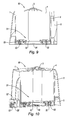
figure 1 est une vue en perspective d'un distributeur à deux logements selon l'invention, un rouleau de papier toilette étant logé dans chacun des logements, une feuille de papier toilette étant en train d'être dévidée depuis chacun des rouleaux ; - la
figure 2 est une vue schématique de dessous du distributeur de lafigure 1 monté en position horizontale ; - la
figure 3 est une vue en perspective du distributeur de lafigure 2 , le compartiment situé à droite du distributeur étant ouvert ; - la
figure 4 est une vue en perspective du distributeur de lafigure 2 , le compartiment situé à gauche du distributeur étant ouvert ; - la
figure 5 est une vue schématique, de dessus, du socle du distributeur selon l'invention avec ses supports de rouleaux ; - la
figure 6 est une vue schématique, de dessous, du socle du distributeur de lafigure 5 ; - la
figure 7 est une vue schématique en perspective du compartiment situé à droite du distributeur selon l'invention, le compartiment situé à gauche étant représenté sans le support de rouleau et sans la porte ; - la
figure 8 est une vue schématique de côté du compartiment situé à droite du distributeur de lafigure 7 et comprenant un axe Y-Y ; - la
figure 9 est une vue en coupe selon l'axe Y-Y du compartiment situé à droite du distributeur de lafigure 8 vu de dessus (avec un léger angle); et - la
figure 10 est une vue en coupe selon l'axe Y-Y du compartiment situé à droite du distributeur de lafigure 8 vu de dessous (avec un léger angle).
- the
figure 1 is a perspective view of a two-slot dispenser according to the invention, a roll of toilet paper being housed in each of the housing, a toilet paper being being unwound from each of the rollers; - the
figure 2 is a schematic bottom view of the distributor of thefigure 1 mounted in a horizontal position; - the
figure 3 is a perspective view of the distributor of thefigure 2 , the compartment to the right of the dispenser being open; - the
figure 4 is a perspective view of the distributor of thefigure 2 , the compartment to the left of the dispenser being open; - the
figure 5 is a schematic view, from above, of the base of the dispenser according to the invention with its roll holders; - the
figure 6 is a schematic view, from below, of the base of the distributor of thefigure 5 ; - the
figure 7 is a schematic perspective view of the compartment to the right of the dispenser according to the invention, the compartment on the left being shown without the roll holder and without the door; - the
figure 8 is a schematic side view of the compartment to the right of the distributor of thefigure 7 and comprising an axis YY; - the
figure 9 is a sectional view along the YY axis of the compartment to the right of the distributor of thefigure 8 seen from above (with a slight angle); and - the
figure 10 is a sectional view along the YY axis of the compartment to the right of the distributor of thefigure 8 seen from below (with a slight angle).
En référence à la
Le papier toilette est ici un papier en ouate de cellulose, comportant par exemple deux plis, ou couches, reliés éventuellement entre eux par tout moyen mécanique ou chimique approprié, par exemple par moletage ou collage, de façon bien connue de l'homme du métier. Le papier toilette se présente sous la forme d'une bande qui est enroulée en un rouleau 4, ce dernier comportant un mandrin interne central ou non, le mandrin étant retiré au moment de la mise en fonction du rouleau. La bande comporte des prédécoupes transversales à la direction de déroulement de la bande, définissant des feuilles de papier qui peuvent être détachées individuellement.Here, the toilet paper is a paper made of cellulose wadding, for example comprising two plies, or layers, possibly interconnected by any appropriate mechanical or chemical means, for example by knurling or gluing, in a manner well known to those skilled in the art. . The toilet paper is in the form of a strip which is wound into a
Le distributeur 10 comprend un boîtier 60, de forme allongée, de réception d'au moins deux rouleaux 4, 4', qui sont de forme cylindrique. Le boîtier 60 est agencé de façon à ce que les rouleaux 4, 4' ne tournent pas sur leur axe lors de leur dévidement.The
Dans cet exemple, le boîtier est formé d'une seule pièce formant un boîtier global. Il va de soi que le boîtier pourrait être formé d'au moins deux boîtiers individuels montés ensemble par exemple au moyen de clips.In this example, the housing is formed of a single piece forming a global housing. It goes without saying that the housing could be formed of at least two individual housings mounted together for example by means of clips.
En référence aux
Par la suite, on définit les termes « gauche » et « droite » par rapport à la
Le distributeur 10 va être maintenant décrit en détails.The
En référence à la
Les logements 51, 51' sont formés dans l'épaisseur du socle. Les logements 51, 51' sont ici circulaires pour accueillir respectivement les rouleaux de papier toilette 4, 4' de forme tubulaire.The
Chaque logement 51, 51' comprend des ouvertures traversantes 54 qui sont agencées pour permettre la fixation du socle 5 à une paroi verticale. Dans cet exemple, chaque logement 51, 51' comprend une pluralité d'ouvertures traversantes 54, dont une centrale, se présentant sous la forme d'une rainure longitudinale comportant dans son milieu une ouverture circulaire. De manière connue, cela permet de fixer manuellement le distributeur 10 à une paroi dans laquelle sont fixées des vis.Each
La pluralité d'ouverture 54 est conçue pour que le distributeur 10 puisse être monté en position horizontale (si la grande dimension du distributeur est horizontale), en position verticale (si la grande dimension du distributeur est verticale) et en position oblique (si la grande dimension du distributeur est oblique).The plurality of
Par la suite, le distributeur 10 est décrit monté en position horizontale mais il va de soi que le distributeur 10 pourrait également être monté en position verticale ou oblique.Subsequently, the
En référence maintenant aux
Les portes 1, 1' comportent chacune une buse 3, 3' de distribution des bandes de papier toilette des rouleaux 4, 4'.The
Le papier toilette est dévidé à partir du centre du rouleau 4, 4' et extrait par l'orifice de la buse 3, 3'. La buse 3, 3' est généralement de forme tronconique et de faible section de sortie pour imposer une distribution feuille à feuille.The toilet paper is unwound from the center of the
En position de fermeture, les portes 1, 1' protègent les rouleaux 4, 4' contre d'éventuelles agressions extérieures de manière à garantir que le papier toilette demeure hygiénique. A cet effet, les portes 1, 1' sont jointives en position de fermeture de manière à former un capot global pour le distributeur 10. Dans cet exemple, chaque porte 1, 1' se présente sous la forme d'une enveloppe partiellement cylindrique, comprenant une face arrière ouverte pour permettre l'introduction du rouleau 4, 4' dans l'enveloppe lorsque la porte 1, l'est refermée, une face latérale évidée ou semi-évidée vers ladite autre porte 1, 1' et d'autres faces de manière à ce que les portes 1, 1', en position de fermeture, possèdent ensemble une enveloppe continue. Autrement dit, l'association des deux portes 1, 1' en position de fermeture remplit avantageusement la même fonction qu'un unique capot global. Dans d'autres modes de réalisation, la face latérale peut aussi être pleine.In the closed position, the
En position d'ouverture, les portes 1, 1' permettent l'accès aux logements 51, 51' afin de les recharger en rouleaux 4, 4' de manière individuelle. Cela permet de recharger individuellement un logement 51, 51' par ouverture d'une porte 1, 1' tout en laissant l'autre porte 1' 1 en position de fermeture afin qu'elle protège le rouleau 4', 4 en cours d'utilisation.In the open position, the
Dans cet exemple, en référence aux
Autrement dit, toujours pour un distributeur 10 monté horizontalement, lorsque l'on ouvre une porte 1, 1' celle-ci se déplace dans une direction oblique qui comprend une composante verticale mais également une composante horizontale de manière à s'écarter du centre du distributeur 10, i.e. d'un plan (P), le plan (P) correspondant aux faces latérales des portes (1, 1'). En d'autres termes, entre sa position de fermeture et sa position d'ouverture, la porte 1, 1' s'écarte du plan de (P) ce qui permet d'éviter que les portes 1, l'entrent en contact lors de l'ouverture ou de la fermeture d'une des deux portes. De préférence, les charnières 2, 2' sont dans la partie inférieure du distributeur 10 de manière à ce que les portes 1, 1' s'ouvrent essentiellement de haut en bas.In other words, again for a
Les portes 1, 1' comprennent en outre chacune des moyens de verrouillage en fermeture 7, 7' qui se présentent, en référence aux
Toujours en référence à la
En position d'utilisation horizontale, lorsque le distributeur 10 est monté sur une paroi verticale, l'angle α du support 6, 6' est orienté vers le haut de manière à permettre une insertion aisée du rouleau 4, 4' depuis le haut vers le bas, selon une direction verticale. Le support 6, 6' remplit une fonction de support de la masse du rouleau mais également une fonction de protection de la bande du rouleau 4, 4'. Cette dernière fonction sera explicitée par la suite.In the horizontal use position, when the
Dans cet exemple, l'angle α du support 6, 6' est environ de 240° mais il va de soi que tout angle compris entre 180° et 360° pourrait également convenir pour remplir cette double fonction. En effet, avec un tel degré d'ouverture, le support 6, 6' remplit encore sa fonction de support des rouleaux 4, 4' lorsque le distributeur 10 est en position verticale ou oblique.In this example, the angle α of the
En référence maintenant aux
La présence d'une pluralité de ressorts 53, 53' dans un même logement 51, 51' permet avantageusement d'équilibrer la poussée vers l'avant exercée par le plateau poussoir 52, 52' et ainsi de permettre un contact homogène entre le rouleau 4, 4' et sa porte 1, 1'.The presence of a plurality of
Par ailleurs, le plateau poussoir 52, 52' est retenu dans son logement 51, 51' par des butées qui limitent la course du plateau poussoir 52, 52' et évitent ainsi que le plateau poussoir 52, 52' ne se sépare de son logement 51, 51'.Furthermore, the
Selon un autre mode de réalisation, le support du rouleau peut être une partie intégrante ou solidaire du socle.According to another embodiment, the support of the roller may be an integral or integral part of the base.
Selon encore un autre mode de réalisation, le support peut être formé d'une pluralité de zones ou surfaces d'appui maintenant le rouleau en place et assurant la fonction de support dans toutes les directions. Les matériaux de ce support seront choisis de manière appropriée pour remplir cette fonction.According to yet another embodiment, the support may be formed of a plurality of bearing zones or surfaces holding the roller in place and providing the support function in all directions. The materials of this support will be appropriately chosen to fulfill this function.
Une mise en oeuvre de l'invention va être maintenant présentée.An implementation of the invention will now be presented.
Une fois fixé à une paroi verticale dans une position de montage horizontale, les rouleaux 4, 4' s'étendent dans leurs logements 51 orthogonalement au socle 5, la masse des rouleaux 4, 4' étant supportée par les supports 6, 6' qui s'étendent sous les rouleaux 4, 4'. Les supports 6, 6' forment avantageusement des berceaux dans lequel sont reçus les rouleaux 4, 4'.Once attached to a vertical wall in a horizontal mounting position, the
Les rouleaux 4, 4' sont protégés par les portes 1, 1' en position de fermeture qui forment un capot global pour le distributeur 10, les protégeant ainsi contre les attaques extérieures (chocs, liquide, etc.). Une extrémité de bande de papier toilette de chaque rouleau 4, 4' est saillante via la buse de distribution 3, 3' de chacune des portes 1, 1' comme représenté sur la
Outre sa compacité, le distributeur 10 possède un rouleau de réserve 4' ou 4 qui permet de faire face à toute pénurie et/ou limiter le nombre de rechargement. Par ailleurs, les rouleaux 4, 4' sont rechargés indépendamment l'un de l'autre ce qui permet d'utiliser complètement un rouleau 4, 4' avant de le remplacer, le rouleau de réserve 4', 4 permettant d'assurer la transition.In addition to its compactness, the
La bande de papier toilette peut être de différente nature dans chacun des logements (papier normal et papier contre les allergies par exemple), ce qui permet une plus grande flexibilité d'utilisation du distributeur 10. De préférence, la distribution se fait feuille à feuille ce qui entraîne une baisse de la consommation de papier de la part des usagers.The toilet paper strip may be of different types in each of the housings (normal paper and allergy-resistant paper for example), which allows a greater flexibility of use of the
Par ailleurs, les portes 1, 1' sont verrouillées au socle 5 par les moyens de verrouillage 7, 7' afin d'éviter tout vol de rouleaux 4, 4'.Furthermore, the
A titre d'exemple, pour recharger le logement situé à droite 51 du distributeur 10, l'utilisateur chargé de l'entretien doit tout d'abord déverrouiller la porte située à droite 1 de manière à permettre le pivotement de la porte située à droite 1 par rapport au socle 5.For example, to reload the housing on the right 51 of the
Suite à son ouverture, la porte située à droite 1 se déplace dans une direction oblique vers le bas pour venir s'immobiliser sous le distributeur 10 comme représenté sur la
Bien que le support situé à droite 6 ne soit pas représenté sur la
En référence aux
Autrement dit, l'angle α du support 6, 6' est avantageusement calibré pour permettre, d'une part, une introduction aisée d'un rouleau neuf (nécessité d'un petit angle) et, d'autre part, un support et une protection efficace du rouleau entamé quand un rouleau neuf est inséré (nécessité d'un grand angle).In other words, the angle α of the
L'invention a été ici présentée avec un distributeur comprenant deux rouleaux mais il va de soi que le distributeur pourrait comprendre plus de deux rouleaux alignés ou en quinconce dans le distributeur.The invention has been presented here with a dispenser comprising two rollers but it goes without saying that the dispenser could comprise more than two rollers aligned or staggered in the dispenser.
Claims (13)
- Dispenser (10) for paper, in particular absorbent paper, comprising a case (60) in which at least two rolls (4, 4') of a paper web are housed, the case (60) having:- a base unit (5) having at least a first housing and a second housing (51, 51') for holding respectively the at least first and second rolls (4, 4'), characterized in that- at least a first door and a second door (1, 1') mounted on the base unit (5) and arranged, in the closed position, to protect respectively the first and second rolls (4, 4') and, in the open position, to provide access respectively to the first and second housings (51, 51') in order to reload them individually with rolls, the first and second doors (1, 1') having respectively a first and a second nozzle (3, 3') for dispensing the webs from the first and second rolls (4, 4').
- Dispenser (10) according to the preceding claim, in which the doors (1, 1') are contiguous in the closed position.
- Dispenser (10) according to either of the preceding claims, in which the first and second doors (1, 1') are connected to the base unit (5) by pivoting means which are arranged to space the doors (1, 1') apart from one another when the doors (1, 1') are opened.
- Dispenser (10) according to Claim 3, in which the pivoting means are in the form of an oblique hinge (2, 2').
- Dispenser (10) according to the preceding claim, in which each door (1, 1') is in the form of casing comprising:- an open rear face in order to introduce the roll (4, 4') into the casing when the door (1, 1') is closed,- a lateral face towards said other door, and- other faces such that the doors (1, 1') together form a continuous casing when they are in the closed position.
- Dispenser (10) according to one of the preceding claims, in which the first and second housings (51, 51') comprise respectively a first and a second roll holder (6, 6'), said roll holders being arranged to hold respectively the first and second rolls (4, 4') when the dispenser (10) is in the mounted position.
- Dispenser (10) according to Claim 6, in which the geometry and/or dimensions of each roll holder (6, 6') is/are designed to laterally cover the roll (4, 4') held thereby so as to protect said roll laterally when a door (1, 1') is open.
- Dispenser (10) according to either of Claims 6 and 7, in which the roll holders (6, 6') extend at right angles to the base unit (5) at the periphery of the first and second housings (51, 51').
- Dispenser (10) according to one of Claims 6 to 8, in which the roll holders (6, 6') are in the form of a portion of a cylinder.
- Dispenser (10) according to Claim 9, in which the roll holder (6, 6') is hollowed out laterally, and the protruding part of the base unit that holds the roll forms an angle (α) of between 180 and 360°.
- Dispenser (10) according to one of Claims 6 to 10, in which said door (1) engages with said roll holder (6) in its housing (51) in order to provide a continuous separating partition when said door (1') of the housing (51') is open.
- Dispenser (10) according to one of the preceding claims, in which each housing (51, 51') comprises a push plate (52, 52'), elastic means being mounted between the housing (51, 51') and the roll plate (52, 52') so as to space the push plate (52, 52') apart from its housing (51).
- Dispenser according to one of the preceding claims, in which the dispenser is a centrally unwinding dispenser.
Priority Applications (16)
| Application Number | Priority Date | Filing Date | Title |
|---|---|---|---|
| PL10305621T PL2394551T3 (en) | 2010-06-10 | 2010-06-10 | Paper roll dispenser comprising a base and at least one first door and one second door mounted on the base of the dispenser |
| EP20100305621 EP2394551B1 (en) | 2010-06-10 | 2010-06-10 | Paper roll dispenser comprising a base and at least one first door and one second door mounted on the base of the dispenser |
| HUE10305621A HUE025297T2 (en) | 2010-06-10 | 2010-06-10 | Paper roll dispenser comprising a base and at least one first door and one second door mounted on the base of the dispenser |
| ES10305621.4T ES2538216T3 (en) | 2010-06-10 | 2010-06-10 | Roll paper dispenser consisting of a socket and at least a first door and a second door mounted on the dispenser base |
| US13/264,305 US9192268B2 (en) | 2010-06-10 | 2011-06-09 | Dispenser for paper in roll form, having a base unit and at least a first door and a second door installed on the base unit of the dispenser |
| PCT/FR2011/000338 WO2011154625A1 (en) | 2010-06-10 | 2011-06-09 | Paper roll dispenser comprising a base and at least one first door and one second door mounted on the base of the dispenser |
| MX2011010764A MX2011010764A (en) | 2010-06-10 | 2011-06-09 | Paper roll dispenser comprising a base and at least one first door and one second door mounted on the base of the dispenser. |
| MYPI2012005299A MY159002A (en) | 2010-06-10 | 2011-06-09 | Paper roll dispenser comprising a base and at leats one first door and one second door mounted on the base of the dispenser |
| CN201180034154.7A CN103025219B (en) | 2010-06-10 | 2011-06-09 | Paper roll dispenser comprising a base and at least one first door and one second door mounted on the base of the dispenser |
| AU2011263633A AU2011263633B2 (en) | 2010-06-10 | 2011-06-09 | Paper roll dispenser comprising a base and at least one first door and one second door mounted on the base of the dispenser |
| UAA201214965A UA106297C2 (en) | 2010-06-10 | 2011-06-09 | Dispenser for paper in roll form, having base unit and at least first door and second door installed on base unit of dispenser |
| CA2756903A CA2756903C (en) | 2010-06-10 | 2011-06-09 | Dispenser for paper in roll form, having a base unit and at least a first door and a second door installed on the base unit of the dispenser |
| BR112012031256A BR112012031256A2 (en) | 2010-06-10 | 2011-06-09 | paper roll dispenser comprising a base and at least a first door and a second door mounted on the distributor base |
| RU2012156931/12A RU2560392C2 (en) | 2010-06-10 | 2011-06-09 | Device for dispensing roll paper, comprising base and at least one first casing and one second casing, mounted on base of dispensing device |
| CL2012003474A CL2012003474A1 (en) | 2010-06-10 | 2012-12-07 | An absorbent paper dispenser having a box with a base unit that has at least a first and second housing, respectively containing at least a first and second roll, at least a first and second door that respectively have a first and second nozzle for dose the continuous papers from the first and second roll. |
| CO12234440A CO6640326A2 (en) | 2010-06-10 | 2012-12-27 | Roll paper dispenser consisting of a base and at least a first door and a second door, mounted on the base of the dispenser |
Applications Claiming Priority (1)
| Application Number | Priority Date | Filing Date | Title |
|---|---|---|---|
| EP20100305621 EP2394551B1 (en) | 2010-06-10 | 2010-06-10 | Paper roll dispenser comprising a base and at least one first door and one second door mounted on the base of the dispenser |
Publications (2)
| Publication Number | Publication Date |
|---|---|
| EP2394551A1 EP2394551A1 (en) | 2011-12-14 |
| EP2394551B1 true EP2394551B1 (en) | 2015-05-06 |
Family
ID=43027510
Family Applications (1)
| Application Number | Title | Priority Date | Filing Date |
|---|---|---|---|
| EP20100305621 Active EP2394551B1 (en) | 2010-06-10 | 2010-06-10 | Paper roll dispenser comprising a base and at least one first door and one second door mounted on the base of the dispenser |
Country Status (16)
| Country | Link |
|---|---|
| US (1) | US9192268B2 (en) |
| EP (1) | EP2394551B1 (en) |
| CN (1) | CN103025219B (en) |
| AU (1) | AU2011263633B2 (en) |
| BR (1) | BR112012031256A2 (en) |
| CA (1) | CA2756903C (en) |
| CL (1) | CL2012003474A1 (en) |
| CO (1) | CO6640326A2 (en) |
| ES (1) | ES2538216T3 (en) |
| HU (1) | HUE025297T2 (en) |
| MX (1) | MX2011010764A (en) |
| MY (1) | MY159002A (en) |
| PL (1) | PL2394551T3 (en) |
| RU (1) | RU2560392C2 (en) |
| UA (1) | UA106297C2 (en) |
| WO (1) | WO2011154625A1 (en) |
Families Citing this family (23)
| Publication number | Priority date | Publication date | Assignee | Title |
|---|---|---|---|---|
| ES2659726T3 (en) * | 2011-10-21 | 2018-03-19 | Sca Tissue France | Dispenser for static roll without core of central feeding of sheet product |
| DE202012009025U1 (en) * | 2012-09-19 | 2012-12-19 | Sprick Gmbh Bielefelder Papier- Und Wellpappenwerke & Co. | Apparatus for manually generating a spiral packaging material |
| CA2929466C (en) * | 2013-11-04 | 2019-09-03 | Wausau Paper Towel & Tissue, Llc | Dual roll paper towel dispenser |
| US10327601B2 (en) * | 2015-11-16 | 2019-06-25 | Essity Hygiene And Health Aktiebolag | Dispenser for rolls |
| US11395566B2 (en) * | 2016-04-11 | 2022-07-26 | Gpcp Ip Holdings Llc | Sheet product dispenser |
| ES1174610Y (en) * | 2016-12-14 | 2017-04-21 | Borja Carlos Sempere | ROLLER OF A PAPER BAND WITH CONTROLLED DISPENSATION |
| USD878078S1 (en) | 2017-07-13 | 2020-03-17 | Kimberly-Clark Worldwide, Inc. | Paper product dispenser |
| DE102017010909A1 (en) * | 2017-11-24 | 2019-05-29 | Sprick Gmbh Bielefelder Papier- Und Wellpappenwerke & Co. | Apparatus for manually or mechanically producing a tubular packaging material |
| US11000163B2 (en) * | 2018-01-30 | 2021-05-11 | ionogen Inc. | Wipe dispensing |
| CA3089249A1 (en) | 2018-01-30 | 2019-08-08 | ionogen Inc. | Wipe dispensing |
| CA179934S (en) | 2018-02-23 | 2020-03-05 | Cascades Canada Ulc | Dispenser |
| CA179935S (en) | 2018-02-23 | 2020-03-05 | Cascades Canada Ulc | Dispenser |
| CA181664S (en) | 2018-05-29 | 2021-03-08 | Cascades Canada Ulc | Paper dispenser |
| CA181663S (en) | 2018-05-29 | 2021-03-08 | Cascades Canada Ulc | Paper dispenser |
| CA181854S (en) | 2018-06-07 | 2020-03-05 | Cascades Canada Ulc | Paper dispenser |
| CA3059312A1 (en) | 2018-10-22 | 2020-04-22 | Cascades Canada Ulc | Web material dispenser |
| WO2020222829A1 (en) * | 2019-04-30 | 2020-11-05 | Kimberly-Clark Worldwide, Inc. | Multi-roll paper product dispenser |
| USD984824S1 (en) | 2019-05-31 | 2023-05-02 | San Jamar, Inc. | Center pull-through dispenser |
| US11224314B2 (en) | 2019-05-31 | 2022-01-18 | San Jamar, Inc. | Web material center-pull dispenser assembly |
| CN115697156A (en) * | 2020-06-22 | 2023-02-03 | 金伯利-克拉克环球有限公司 | Dispenser for rolled sheet material |
| USD995140S1 (en) | 2020-06-22 | 2023-08-15 | Kimberly-Clark Worldwide, Inc. | Paper product dispenser |
| US20220227568A1 (en) * | 2021-01-19 | 2022-07-21 | Fania Brunache | Glove Dispenser Assembly |
| WO2023186310A1 (en) * | 2022-03-31 | 2023-10-05 | Essity Hygiene And Health Aktiebolag | Dispenser for dispensing web-shaped absorbent material from a centrefeed roll |
Family Cites Families (18)
| Publication number | Priority date | Publication date | Assignee | Title |
|---|---|---|---|---|
| FR451748A (en) | 1912-12-10 | 1913-04-25 | Bilzinger & Lupo Soc | Valve for washbasins |
| US3132782A (en) * | 1961-11-28 | 1964-05-12 | Jr Robert N Coates | Dispenser for rolled materials |
| FR2668694B1 (en) * | 1990-11-06 | 1993-01-22 | Maurice Granger | WIPER MATERIAL DISPENSER WITH CENTRAL WINDING. |
| GB2269361A (en) * | 1992-08-07 | 1994-02-09 | Fort Howard Corp | Successive dispensing from two sheet rolls |
| US5785274A (en) * | 1995-03-31 | 1998-07-28 | Johnson; John R. | Center feed toilet paper dispenser |
| GB9512835D0 (en) * | 1995-06-23 | 1995-08-23 | Morand Michael | Paper towel dispenser for dispensing paper towels from inside diameter of coreless roll |
| US6056233A (en) * | 1996-11-01 | 2000-05-02 | Von Schenk; David R. | Protective housing for bathroom toilet paper |
| FR2761252B1 (en) | 1997-03-28 | 1999-04-30 | Fort James France | ONE-TO-ONE SHEET DISTRIBUTION SYSTEM |
| US6189730B1 (en) * | 1997-10-14 | 2001-02-20 | Mcclymonds Arnold J. | Wet towelette and dry towel dispenser apparatus |
| US6089499A (en) * | 1997-10-17 | 2000-07-18 | Robinson; Robert S. | Dual roll, center pull, paper toweling dispenser |
| ATE401028T1 (en) * | 2001-12-07 | 2008-08-15 | Audag Ag | DISPENSER FOR HYGIENE PAPER OR CLEANING CLOTHS |
| US20050051568A1 (en) * | 2003-09-04 | 2005-03-10 | Allen Young | Multi-chamber wipe container |
| US7293738B2 (en) * | 2003-11-26 | 2007-11-13 | Kimberly-Clark Worldwide, Inc. | Freestanding dispenser for dispensing two different substrates |
| US7806291B2 (en) * | 2005-05-19 | 2010-10-05 | Buckeye Technologies | Center-pull dispenser for web material |
| US7374128B2 (en) | 2005-07-15 | 2008-05-20 | Hendrix Roy D | Multiple toilet paper holder and dispenser |
| FR2893495B1 (en) * | 2005-11-18 | 2008-02-15 | Georgia Pacific France Soc En | PAPER DISPENSER |
| GB2439538B (en) * | 2006-06-13 | 2008-11-12 | Brightwell Dispensers Ltd | Sheets dispenser |
| GB2466658B (en) | 2009-01-03 | 2010-12-15 | Michael John Gordon | A wipe container and housing system |
-
2010
- 2010-06-10 EP EP20100305621 patent/EP2394551B1/en active Active
- 2010-06-10 HU HUE10305621A patent/HUE025297T2/en unknown
- 2010-06-10 ES ES10305621.4T patent/ES2538216T3/en active Active
- 2010-06-10 PL PL10305621T patent/PL2394551T3/en unknown
-
2011
- 2011-06-09 UA UAA201214965A patent/UA106297C2/en unknown
- 2011-06-09 WO PCT/FR2011/000338 patent/WO2011154625A1/en active Application Filing
- 2011-06-09 MY MYPI2012005299A patent/MY159002A/en unknown
- 2011-06-09 AU AU2011263633A patent/AU2011263633B2/en active Active
- 2011-06-09 BR BR112012031256A patent/BR112012031256A2/en not_active IP Right Cessation
- 2011-06-09 US US13/264,305 patent/US9192268B2/en active Active
- 2011-06-09 RU RU2012156931/12A patent/RU2560392C2/en active
- 2011-06-09 MX MX2011010764A patent/MX2011010764A/en active IP Right Grant
- 2011-06-09 CA CA2756903A patent/CA2756903C/en active Active
- 2011-06-09 CN CN201180034154.7A patent/CN103025219B/en active Active
-
2012
- 2012-12-07 CL CL2012003474A patent/CL2012003474A1/en unknown
- 2012-12-27 CO CO12234440A patent/CO6640326A2/en active IP Right Grant
Also Published As
| Publication number | Publication date |
|---|---|
| CA2756903C (en) | 2018-04-24 |
| HUE025297T2 (en) | 2016-02-29 |
| RU2012156931A (en) | 2014-07-20 |
| BR112012031256A2 (en) | 2016-11-01 |
| CA2756903A1 (en) | 2011-12-10 |
| MX2011010764A (en) | 2012-01-30 |
| US20120175455A1 (en) | 2012-07-12 |
| CN103025219A (en) | 2013-04-03 |
| RU2560392C2 (en) | 2015-08-20 |
| AU2011263633A1 (en) | 2013-01-24 |
| MY159002A (en) | 2016-11-30 |
| ES2538216T3 (en) | 2015-06-18 |
| CL2012003474A1 (en) | 2013-08-02 |
| US9192268B2 (en) | 2015-11-24 |
| WO2011154625A8 (en) | 2012-05-03 |
| CN103025219B (en) | 2017-05-24 |
| AU2011263633B2 (en) | 2015-04-30 |
| WO2011154625A1 (en) | 2011-12-15 |
| EP2394551A1 (en) | 2011-12-14 |
| UA106297C2 (en) | 2014-08-11 |
| CO6640326A2 (en) | 2013-03-22 |
| PL2394551T3 (en) | 2015-11-30 |
Similar Documents
| Publication | Publication Date | Title |
|---|---|---|
| EP2394551B1 (en) | Paper roll dispenser comprising a base and at least one first door and one second door mounted on the base of the dispenser | |
| EP1799083B1 (en) | Toilet paper dispenser housing a roll, toilet paper roll and dispenser | |
| EP2303081B1 (en) | Pre-cut wiping material dispensing apparatus | |
| CA1160653A (en) | Sheet material dispenser | |
| EP1951096B1 (en) | Paper dispenser | |
| EP0814695B1 (en) | Loading device for a wiping material dispensing apparatus | |
| EP2663218B1 (en) | Apparatus for dispensing precut spooled or z-folded wiping material | |
| WO1998002078A1 (en) | Paper dispenser containing a removable case | |
| EP0854686A1 (en) | Wiping material dispenser apparatus with a spare roll loading device | |
| EP0987975B1 (en) | Apparatus dispensing unfolded wiping material | |
| FR2520338A1 (en) | SHEET MATERIAL DISPENSER | |
| FR2818253A1 (en) | PACKAGING PACKAGE | |
| FR2600991A1 (en) | Dispenser of stacked thin elements, fitted with a device for extracting these, and cartridge box of thin elements which is capable of equipping such a dispenser | |
| EP1915934B1 (en) | Multiple roll dispenser | |
| WO2006021701A1 (en) | Device for loading rolls of wiping materials in an automatic-strip-cutting dispenser | |
| EP0586272B1 (en) | Dispenser for rolled-up paper | |
| FR2470579A1 (en) | Wall mounted paper sheet dispenser - has hinged front panel with dispensing slot and internal flanges to support stack or roll | |
| FR2632934A1 (en) | Dispensing package for rolls of paper for household and/or professional uses | |
| EP0714841A1 (en) | Method and apparatus for dispensing objects | |
| EP1540199A1 (en) | Spring and dispenser comprising same | |
| EP0192545B1 (en) | Dispenser of paper rolls | |
| FR2744704A1 (en) | Box for dispensing material in strip or sheet form | |
| EP0084302A2 (en) | Dispensing device for materials rolled on a holder | |
| FR2775579A1 (en) | Sheet by sheet toilet paper dispenser | |
| BE851104A (en) | DISPENSER OF A SHEET OR TABLECLOTH IN THE FORM OF A ROLL |
Legal Events
| Date | Code | Title | Description |
|---|---|---|---|
| 17P | Request for examination filed |
Effective date: 20100610 |
|
| AK | Designated contracting states |
Kind code of ref document: A1 Designated state(s): AL AT BE BG CH CY CZ DE DK EE ES FI FR GB GR HR HU IE IS IT LI LT LU LV MC MK MT NL NO PL PT RO SE SI SK SM TR |
|
| AX | Request for extension of the european patent |
Extension state: BA ME RS |
|
| PUAI | Public reference made under article 153(3) epc to a published international application that has entered the european phase |
Free format text: ORIGINAL CODE: 0009012 |
|
| RAP1 | Party data changed (applicant data changed or rights of an application transferred) |
Owner name: SCA TISSUE FRANCE |
|
| GRAP | Despatch of communication of intention to grant a patent |
Free format text: ORIGINAL CODE: EPIDOSNIGR1 |
|
| RIC1 | Information provided on ipc code assigned before grant |
Ipc: A47K 10/38 20060101AFI20141218BHEP |
|
| INTG | Intention to grant announced |
Effective date: 20150109 |
|
| GRAS | Grant fee paid |
Free format text: ORIGINAL CODE: EPIDOSNIGR3 |
|
| GRAA | (expected) grant |
Free format text: ORIGINAL CODE: 0009210 |
|
| AK | Designated contracting states |
Kind code of ref document: B1 Designated state(s): AL AT BE BG CH CY CZ DE DK EE ES FI FR GB GR HR HU IE IS IT LI LT LU LV MC MK MT NL NO PL PT RO SE SI SK SM TR |
|
| AX | Request for extension of the european patent |
Extension state: BA ME RS |
|
| REG | Reference to a national code |
Ref country code: GB Ref legal event code: FG4D Free format text: NOT ENGLISH |
|
| REG | Reference to a national code |
Ref country code: CH Ref legal event code: EP |
|
| REG | Reference to a national code |
Ref country code: IE Ref legal event code: FG4D Free format text: LANGUAGE OF EP DOCUMENT: FRENCH |
|
| REG | Reference to a national code |
Ref country code: AT Ref legal event code: REF Ref document number: 725115 Country of ref document: AT Kind code of ref document: T Effective date: 20150615 |
|
| REG | Reference to a national code |
Ref country code: DE Ref legal event code: R096 Ref document number: 602010024443 Country of ref document: DE Effective date: 20150618 Ref country code: ES Ref legal event code: FG2A Ref document number: 2538216 Country of ref document: ES Kind code of ref document: T3 Effective date: 20150618 |
|
| REG | Reference to a national code |
Ref country code: NL Ref legal event code: T3 |
|
| REG | Reference to a national code |
Ref country code: SE Ref legal event code: TRGR |
|
| REG | Reference to a national code |
Ref country code: FR Ref legal event code: PLFP Year of fee payment: 6 |
|
| RAP2 | Party data changed (patent owner data changed or rights of a patent transferred) |
Owner name: SCA TISSUE FRANCE |
|
| REG | Reference to a national code |
Ref country code: AT Ref legal event code: MK05 Ref document number: 725115 Country of ref document: AT Kind code of ref document: T Effective date: 20150506 |
|
| REG | Reference to a national code |
Ref country code: LT Ref legal event code: MG4D |
|
| PG25 | Lapsed in a contracting state [announced via postgrant information from national office to epo] |
Ref country code: HR Free format text: LAPSE BECAUSE OF FAILURE TO SUBMIT A TRANSLATION OF THE DESCRIPTION OR TO PAY THE FEE WITHIN THE PRESCRIBED TIME-LIMIT Effective date: 20150506 Ref country code: PT Free format text: LAPSE BECAUSE OF FAILURE TO SUBMIT A TRANSLATION OF THE DESCRIPTION OR TO PAY THE FEE WITHIN THE PRESCRIBED TIME-LIMIT Effective date: 20150907 Ref country code: NO Free format text: LAPSE BECAUSE OF FAILURE TO SUBMIT A TRANSLATION OF THE DESCRIPTION OR TO PAY THE FEE WITHIN THE PRESCRIBED TIME-LIMIT Effective date: 20150806 Ref country code: LT Free format text: LAPSE BECAUSE OF FAILURE TO SUBMIT A TRANSLATION OF THE DESCRIPTION OR TO PAY THE FEE WITHIN THE PRESCRIBED TIME-LIMIT Effective date: 20150506 |
|
| PG25 | Lapsed in a contracting state [announced via postgrant information from national office to epo] |
Ref country code: BG Free format text: LAPSE BECAUSE OF FAILURE TO SUBMIT A TRANSLATION OF THE DESCRIPTION OR TO PAY THE FEE WITHIN THE PRESCRIBED TIME-LIMIT Effective date: 20150806 Ref country code: GR Free format text: LAPSE BECAUSE OF FAILURE TO SUBMIT A TRANSLATION OF THE DESCRIPTION OR TO PAY THE FEE WITHIN THE PRESCRIBED TIME-LIMIT Effective date: 20150807 Ref country code: LV Free format text: LAPSE BECAUSE OF FAILURE TO SUBMIT A TRANSLATION OF THE DESCRIPTION OR TO PAY THE FEE WITHIN THE PRESCRIBED TIME-LIMIT Effective date: 20150506 Ref country code: AT Free format text: LAPSE BECAUSE OF FAILURE TO SUBMIT A TRANSLATION OF THE DESCRIPTION OR TO PAY THE FEE WITHIN THE PRESCRIBED TIME-LIMIT Effective date: 20150506 Ref country code: IS Free format text: LAPSE BECAUSE OF FAILURE TO SUBMIT A TRANSLATION OF THE DESCRIPTION OR TO PAY THE FEE WITHIN THE PRESCRIBED TIME-LIMIT Effective date: 20150906 |
|
| REG | Reference to a national code |
Ref country code: PL Ref legal event code: T3 |
|
| REG | Reference to a national code |
Ref country code: SK Ref legal event code: T3 Ref document number: E 19327 Country of ref document: SK |
|
| PG25 | Lapsed in a contracting state [announced via postgrant information from national office to epo] |
Ref country code: IT Free format text: LAPSE BECAUSE OF NON-PAYMENT OF DUE FEES Effective date: 20150610 Ref country code: EE Free format text: LAPSE BECAUSE OF FAILURE TO SUBMIT A TRANSLATION OF THE DESCRIPTION OR TO PAY THE FEE WITHIN THE PRESCRIBED TIME-LIMIT Effective date: 20150506 Ref country code: DK Free format text: LAPSE BECAUSE OF FAILURE TO SUBMIT A TRANSLATION OF THE DESCRIPTION OR TO PAY THE FEE WITHIN THE PRESCRIBED TIME-LIMIT Effective date: 20150506 |
|
| REG | Reference to a national code |
Ref country code: CH Ref legal event code: PL |
|
| REG | Reference to a national code |
Ref country code: DE Ref legal event code: R097 Ref document number: 602010024443 Country of ref document: DE |
|
| PG25 | Lapsed in a contracting state [announced via postgrant information from national office to epo] |
Ref country code: CZ Free format text: LAPSE BECAUSE OF FAILURE TO SUBMIT A TRANSLATION OF THE DESCRIPTION OR TO PAY THE FEE WITHIN THE PRESCRIBED TIME-LIMIT Effective date: 20150506 Ref country code: RO Free format text: LAPSE BECAUSE OF NON-PAYMENT OF DUE FEES Effective date: 20150506 Ref country code: MC Free format text: LAPSE BECAUSE OF FAILURE TO SUBMIT A TRANSLATION OF THE DESCRIPTION OR TO PAY THE FEE WITHIN THE PRESCRIBED TIME-LIMIT Effective date: 20150506 |
|
| REG | Reference to a national code |
Ref country code: HU Ref legal event code: AG4A Ref document number: E025297 Country of ref document: HU |
|
| PLBE | No opposition filed within time limit |
Free format text: ORIGINAL CODE: 0009261 |
|
| STAA | Information on the status of an ep patent application or granted ep patent |
Free format text: STATUS: NO OPPOSITION FILED WITHIN TIME LIMIT |
|
| REG | Reference to a national code |
Ref country code: IE Ref legal event code: MM4A |
|
| 26N | No opposition filed |
Effective date: 20160209 |
|
| PG25 | Lapsed in a contracting state [announced via postgrant information from national office to epo] |
Ref country code: IE Free format text: LAPSE BECAUSE OF NON-PAYMENT OF DUE FEES Effective date: 20150610 Ref country code: LI Free format text: LAPSE BECAUSE OF NON-PAYMENT OF DUE FEES Effective date: 20150630 Ref country code: CH Free format text: LAPSE BECAUSE OF NON-PAYMENT OF DUE FEES Effective date: 20150630 |
|
| PGRI | Patent reinstated in contracting state [announced from national office to epo] |
Ref country code: IT Effective date: 20160412 |
|
| REG | Reference to a national code |
Ref country code: FR Ref legal event code: PLFP Year of fee payment: 7 |
|
| PG25 | Lapsed in a contracting state [announced via postgrant information from national office to epo] |
Ref country code: SI Free format text: LAPSE BECAUSE OF FAILURE TO SUBMIT A TRANSLATION OF THE DESCRIPTION OR TO PAY THE FEE WITHIN THE PRESCRIBED TIME-LIMIT Effective date: 20150506 |
|
| PG25 | Lapsed in a contracting state [announced via postgrant information from national office to epo] |
Ref country code: MT Free format text: LAPSE BECAUSE OF FAILURE TO SUBMIT A TRANSLATION OF THE DESCRIPTION OR TO PAY THE FEE WITHIN THE PRESCRIBED TIME-LIMIT Effective date: 20150506 |
|
| REG | Reference to a national code |
Ref country code: FR Ref legal event code: PLFP Year of fee payment: 8 |
|
| PG25 | Lapsed in a contracting state [announced via postgrant information from national office to epo] |
Ref country code: SM Free format text: LAPSE BECAUSE OF FAILURE TO SUBMIT A TRANSLATION OF THE DESCRIPTION OR TO PAY THE FEE WITHIN THE PRESCRIBED TIME-LIMIT Effective date: 20150506 |
|
| PG25 | Lapsed in a contracting state [announced via postgrant information from national office to epo] |
Ref country code: CY Free format text: LAPSE BECAUSE OF FAILURE TO SUBMIT A TRANSLATION OF THE DESCRIPTION OR TO PAY THE FEE WITHIN THE PRESCRIBED TIME-LIMIT Effective date: 20150506 |
|
| PG25 | Lapsed in a contracting state [announced via postgrant information from national office to epo] |
Ref country code: BE Free format text: LAPSE BECAUSE OF NON-PAYMENT OF DUE FEES Effective date: 20150630 |
|
| PGFP | Annual fee paid to national office [announced via postgrant information from national office to epo] |
Ref country code: CH Payment date: 20170527 Year of fee payment: 14 |
|
| PGFP | Annual fee paid to national office [announced via postgrant information from national office to epo] |
Ref country code: SE Payment date: 20170526 Year of fee payment: 8 Ref country code: FI Payment date: 20170523 Year of fee payment: 8 |
|
| PGFP | Annual fee paid to national office [announced via postgrant information from national office to epo] |
Ref country code: HU Payment date: 20170615 Year of fee payment: 8 |
|
| PG25 | Lapsed in a contracting state [announced via postgrant information from national office to epo] |
Ref country code: LU Free format text: LAPSE BECAUSE OF NON-PAYMENT OF DUE FEES Effective date: 20150610 |
|
| REG | Reference to a national code |
Ref country code: FR Ref legal event code: PLFP Year of fee payment: 9 |
|
| PG25 | Lapsed in a contracting state [announced via postgrant information from national office to epo] |
Ref country code: MK Free format text: LAPSE BECAUSE OF FAILURE TO SUBMIT A TRANSLATION OF THE DESCRIPTION OR TO PAY THE FEE WITHIN THE PRESCRIBED TIME-LIMIT Effective date: 20150506 |
|
| REG | Reference to a national code |
Ref country code: NL Ref legal event code: HC Owner name: ESSITY OPERATIONS FRANCE; FR Free format text: DETAILS ASSIGNMENT: CHANGE OF OWNER(S), CHANGE OF OWNER(S) NAME; FORMER OWNER NAME: SCA TISSUE FRANCE Effective date: 20180720 |
|
| REG | Reference to a national code |
Ref country code: DE Ref legal event code: R081 Ref document number: 602010024443 Country of ref document: DE Owner name: ESSITY OPERATIONS FRANCE, FR Free format text: FORMER OWNER: SCA TISSUE FRANCE, BOIS-COLOMBES, FR |
|
| PG25 | Lapsed in a contracting state [announced via postgrant information from national office to epo] |
Ref country code: AL Free format text: LAPSE BECAUSE OF FAILURE TO SUBMIT A TRANSLATION OF THE DESCRIPTION OR TO PAY THE FEE WITHIN THE PRESCRIBED TIME-LIMIT Effective date: 20150506 |
|
| REG | Reference to a national code |
Ref country code: ES Ref legal event code: PC2A Owner name: ESSITY OPERATIONS FRANCE Effective date: 20190104 |
|
| REG | Reference to a national code |
Ref country code: SE Ref legal event code: EUG |
|
| PG25 | Lapsed in a contracting state [announced via postgrant information from national office to epo] |
Ref country code: FI Free format text: LAPSE BECAUSE OF NON-PAYMENT OF DUE FEES Effective date: 20180610 Ref country code: SE Free format text: LAPSE BECAUSE OF NON-PAYMENT OF DUE FEES Effective date: 20180611 |
|
| REG | Reference to a national code |
Ref country code: SK Ref legal event code: MM4A Ref document number: E 19327 Country of ref document: SK Effective date: 20180610 |
|
| PG25 | Lapsed in a contracting state [announced via postgrant information from national office to epo] |
Ref country code: HU Free format text: LAPSE BECAUSE OF NON-PAYMENT OF DUE FEES Effective date: 20180611 |
|
| PG25 | Lapsed in a contracting state [announced via postgrant information from national office to epo] |
Ref country code: SK Free format text: LAPSE BECAUSE OF NON-PAYMENT OF DUE FEES Effective date: 20180610 |
|
| REG | Reference to a national code |
Ref country code: FR Ref legal event code: PLFP Year of fee payment: 14 |
|
| PGFP | Annual fee paid to national office [announced via postgrant information from national office to epo] |
Ref country code: PL Payment date: 20230328 Year of fee payment: 14 |
|
| P01 | Opt-out of the competence of the unified patent court (upc) registered |
Effective date: 20230516 |
|
| PGFP | Annual fee paid to national office [announced via postgrant information from national office to epo] |
Ref country code: NL Payment date: 20230417 Year of fee payment: 14 |
|
| PGFP | Annual fee paid to national office [announced via postgrant information from national office to epo] |
Ref country code: IT Payment date: 20230510 Year of fee payment: 14 Ref country code: FR Payment date: 20230411 Year of fee payment: 14 Ref country code: DE Payment date: 20230418 Year of fee payment: 14 |
|
| PGFP | Annual fee paid to national office [announced via postgrant information from national office to epo] |
Ref country code: TR Payment date: 20230609 Year of fee payment: 14 |
|
| PGFP | Annual fee paid to national office [announced via postgrant information from national office to epo] |
Ref country code: GB Payment date: 20230420 Year of fee payment: 14 Ref country code: ES Payment date: 20230707 Year of fee payment: 14 |