EP2394337B1 - Spleissanordnung mit schutzstrumpf - Google Patents
Spleissanordnung mit schutzstrumpf Download PDFInfo
- Publication number
- EP2394337B1 EP2394337B1 EP10739022.1A EP10739022A EP2394337B1 EP 2394337 B1 EP2394337 B1 EP 2394337B1 EP 10739022 A EP10739022 A EP 10739022A EP 2394337 B1 EP2394337 B1 EP 2394337B1
- Authority
- EP
- European Patent Office
- Prior art keywords
- splice
- shield sock
- assembly
- cold shrink
- sock
- Prior art date
- Legal status (The legal status is an assumption and is not a legal conclusion. Google has not performed a legal analysis and makes no representation as to the accuracy of the status listed.)
- Active
Links
- 239000010410 layer Substances 0.000 description 38
- 239000000463 material Substances 0.000 description 25
- 229920001971 elastomer Polymers 0.000 description 7
- 239000005060 rubber Substances 0.000 description 7
- RYGMFSIKBFXOCR-UHFFFAOYSA-N Copper Chemical compound [Cu] RYGMFSIKBFXOCR-UHFFFAOYSA-N 0.000 description 6
- 239000004020 conductor Substances 0.000 description 6
- 229910052802 copper Inorganic materials 0.000 description 6
- 239000010949 copper Substances 0.000 description 6
- 238000000034 method Methods 0.000 description 6
- 229910052782 aluminium Inorganic materials 0.000 description 4
- XAGFODPZIPBFFR-UHFFFAOYSA-N aluminium Chemical compound [Al] XAGFODPZIPBFFR-UHFFFAOYSA-N 0.000 description 4
- 239000000945 filler Substances 0.000 description 4
- 239000002356 single layer Substances 0.000 description 4
- 229920002725 thermoplastic elastomer Polymers 0.000 description 4
- 230000008901 benefit Effects 0.000 description 3
- 230000005611 electricity Effects 0.000 description 3
- 229920001973 fluoroelastomer Polymers 0.000 description 3
- 238000009413 insulation Methods 0.000 description 3
- 239000013521 mastic Substances 0.000 description 3
- 229920002943 EPDM rubber Polymers 0.000 description 2
- PPBRXRYQALVLMV-UHFFFAOYSA-N Styrene Chemical compound C=CC1=CC=CC=C1 PPBRXRYQALVLMV-UHFFFAOYSA-N 0.000 description 2
- 238000010276 construction Methods 0.000 description 2
- 229920001577 copolymer Polymers 0.000 description 2
- 238000009434 installation Methods 0.000 description 2
- 229910052751 metal Inorganic materials 0.000 description 2
- 239000002184 metal Substances 0.000 description 2
- 230000001681 protective effect Effects 0.000 description 2
- 229920002379 silicone rubber Polymers 0.000 description 2
- 229920003048 styrene butadiene rubber Polymers 0.000 description 2
- -1 typically Polymers 0.000 description 2
- BRLQWZUYTZBJKN-UHFFFAOYSA-N Epichlorohydrin Chemical compound ClCC1CO1 BRLQWZUYTZBJKN-UHFFFAOYSA-N 0.000 description 1
- 239000004593 Epoxy Substances 0.000 description 1
- 229920000459 Nitrile rubber Polymers 0.000 description 1
- 239000004902 Softening Agent Substances 0.000 description 1
- 229920000800 acrylic rubber Polymers 0.000 description 1
- 239000000654 additive Substances 0.000 description 1
- 150000001336 alkenes Chemical class 0.000 description 1
- 239000000956 alloy Substances 0.000 description 1
- 229910045601 alloy Inorganic materials 0.000 description 1
- 230000004075 alteration Effects 0.000 description 1
- 239000002216 antistatic agent Substances 0.000 description 1
- 230000000712 assembly Effects 0.000 description 1
- 238000000429 assembly Methods 0.000 description 1
- NTXGQCSETZTARF-UHFFFAOYSA-N buta-1,3-diene;prop-2-enenitrile Chemical compound C=CC=C.C=CC#N NTXGQCSETZTARF-UHFFFAOYSA-N 0.000 description 1
- 229920005549 butyl rubber Polymers 0.000 description 1
- 239000003795 chemical substances by application Substances 0.000 description 1
- 239000003086 colorant Substances 0.000 description 1
- 230000006835 compression Effects 0.000 description 1
- 238000007906 compression Methods 0.000 description 1
- 239000000470 constituent Substances 0.000 description 1
- 238000004132 cross linking Methods 0.000 description 1
- 239000003431 cross linking reagent Substances 0.000 description 1
- 230000007613 environmental effect Effects 0.000 description 1
- 125000003700 epoxy group Chemical group 0.000 description 1
- 229920006229 ethylene acrylic elastomer Polymers 0.000 description 1
- 238000001125 extrusion Methods 0.000 description 1
- 239000003063 flame retardant Substances 0.000 description 1
- 239000012530 fluid Substances 0.000 description 1
- 239000004519 grease Substances 0.000 description 1
- 229920006168 hydrated nitrile rubber Polymers 0.000 description 1
- 239000011810 insulating material Substances 0.000 description 1
- 239000012212 insulator Substances 0.000 description 1
- 239000000314 lubricant Substances 0.000 description 1
- 238000012986 modification Methods 0.000 description 1
- 230000004048 modification Effects 0.000 description 1
- 230000007935 neutral effect Effects 0.000 description 1
- JRZJOMJEPLMPRA-UHFFFAOYSA-N olefin Natural products CCCCCCCC=C JRZJOMJEPLMPRA-UHFFFAOYSA-N 0.000 description 1
- 230000037361 pathway Effects 0.000 description 1
- 230000002093 peripheral effect Effects 0.000 description 1
- 230000000704 physical effect Effects 0.000 description 1
- 239000004033 plastic Substances 0.000 description 1
- 229920003023 plastic Polymers 0.000 description 1
- 229920001084 poly(chloroprene) Polymers 0.000 description 1
- 229920000058 polyacrylate Polymers 0.000 description 1
- 229920000647 polyepoxide Polymers 0.000 description 1
- 229920001195 polyisoprene Polymers 0.000 description 1
- 229920000642 polymer Polymers 0.000 description 1
- 238000010248 power generation Methods 0.000 description 1
- 230000008569 process Effects 0.000 description 1
- 230000004044 response Effects 0.000 description 1
- 238000007789 sealing Methods 0.000 description 1
- 239000004065 semiconductor Substances 0.000 description 1
- 239000004945 silicone rubber Substances 0.000 description 1
- XLYOFNOQVPJJNP-UHFFFAOYSA-N water Substances O XLYOFNOQVPJJNP-UHFFFAOYSA-N 0.000 description 1
Images


Classifications
-
- H—ELECTRICITY
- H02—GENERATION; CONVERSION OR DISTRIBUTION OF ELECTRIC POWER
- H02G—INSTALLATION OF ELECTRIC CABLES OR LINES, OR OF COMBINED OPTICAL AND ELECTRIC CABLES OR LINES
- H02G15/00—Cable fittings
- H02G15/08—Cable junctions
- H02G15/085—Cable junctions for coaxial cables or hollow conductors
-
- H—ELECTRICITY
- H02—GENERATION; CONVERSION OR DISTRIBUTION OF ELECTRIC POWER
- H02G—INSTALLATION OF ELECTRIC CABLES OR LINES, OR OF COMBINED OPTICAL AND ELECTRIC CABLES OR LINES
- H02G15/00—Cable fittings
- H02G15/08—Cable junctions
- H02G15/18—Cable junctions protected by sleeves, e.g. for communication cable
- H02G15/182—Cable junctions protected by sleeves, e.g. for communication cable held in expanded condition in radial direction prior to installation
- H02G15/1826—Cable junctions protected by sleeves, e.g. for communication cable held in expanded condition in radial direction prior to installation on a removable hollow core, e.g. a tube
- H02G15/1833—Cable junctions protected by sleeves, e.g. for communication cable held in expanded condition in radial direction prior to installation on a removable hollow core, e.g. a tube formed of helically wound strip with adjacent windings, which are removable by applying a pulling force to a strip end
-
- H—ELECTRICITY
- H02—GENERATION; CONVERSION OR DISTRIBUTION OF ELECTRIC POWER
- H02G—INSTALLATION OF ELECTRIC CABLES OR LINES, OR OF COMBINED OPTICAL AND ELECTRIC CABLES OR LINES
- H02G15/00—Cable fittings
- H02G15/08—Cable junctions
- H02G15/10—Cable junctions protected by boxes, e.g. by distribution, connection or junction boxes
- H02G15/103—Cable junctions protected by boxes, e.g. by distribution, connection or junction boxes with devices for relieving electrical stress
-
- H—ELECTRICITY
- H02—GENERATION; CONVERSION OR DISTRIBUTION OF ELECTRIC POWER
- H02G—INSTALLATION OF ELECTRIC CABLES OR LINES, OR OF COMBINED OPTICAL AND ELECTRIC CABLES OR LINES
- H02G3/00—Installations of electric cables or lines or protective tubing therefor in or on buildings, equivalent structures or vehicles
- H02G3/02—Details
- H02G3/06—Joints for connecting lengths of protective tubing or channels, to each other or to casings, e.g. to distribution boxes; Ensuring electrical continuity in the joint
-
- Y—GENERAL TAGGING OF NEW TECHNOLOGICAL DEVELOPMENTS; GENERAL TAGGING OF CROSS-SECTIONAL TECHNOLOGIES SPANNING OVER SEVERAL SECTIONS OF THE IPC; TECHNICAL SUBJECTS COVERED BY FORMER USPC CROSS-REFERENCE ART COLLECTIONS [XRACs] AND DIGESTS
- Y10—TECHNICAL SUBJECTS COVERED BY FORMER USPC
- Y10T—TECHNICAL SUBJECTS COVERED BY FORMER US CLASSIFICATION
- Y10T29/00—Metal working
- Y10T29/49—Method of mechanical manufacture
- Y10T29/49002—Electrical device making
- Y10T29/49117—Conductor or circuit manufacturing
- Y10T29/49194—Assembling elongated conductors, e.g., splicing, etc.
- Y10T29/49195—Assembling elongated conductors, e.g., splicing, etc. with end-to-end orienting
Definitions
- This disclosure relates broadly to splices for electrical cables.
- Electric cables are broadly employed in a variety of industries including power supply and generation. Some electrical cables distribute power across vast power grids or networks, moving electricity from power generation plants to the consumers of electrical power, and moving electricity from one power grid to another power grid. Other electrical cables are employed in wiring homes and/or businesses.
- Electrical cables generally include a conductive core (typically copper or aluminum) and may include one or more layers of surrounding insulating material and one or more conductive or semiconductive layers. Some power cables include multiple twisted conductive wires. Electrical cables are constructed to carry high voltages (greater than about 50,000 volts), medium voltages (between about 1,000 volts and about 50,000 volts), or low voltages (less than about a 1,000 volts).
- a splice or a junction in the cable, for example, to electrically connect two or more electrical devices or to distribute electricity to additional branches of a power grid. Such branches may be further distributed until the grid reaches individual homes, businesses, offices.
- a single power cable supplying electrical power to a group of several buildings is commonly branched to each of the buildings.
- the terms "splice" and “junction” are used interchangeably, and in each case refer to the portion of an electrical system where an incoming cable is connected to at least one outgoing cable.
- two extruded layers are used, namely an insulation layer and a shielding layer, which are either individually placed onto the support core, one after the other, or they are manufactured in a co-extrusion process.
- a copper braid is coaxially arranged. Adjacent the ends of the copper braid two additional mastic layers are provided.
- the mastic layers are chosen so that they can provide the necessary sealing against water or humidity and are also capable of shrinking down to a reduced diameter upon removal of the core.
- a cable jacket replacement which is an expanded tube, is placed onto the support core such that it covers all the other components.
- an assembly is provided according to claim 1.
- an article is according to claim 2.
- a kit in some embodiments, includes an assembly as described above and herein, clamps, and, optionally, a cold shrink short jacket.
- the various embodiments of the provided assembly, article, method of forming an electrical splice, and kit provide advantages over the art in the following ways.
- the thinner wire also allows formed splices to be much more flexible than those with thicker wire.
- the assembly includes a conductive shield sock having one or more sections, each of which section has two ends. The ends may be ragged or otherwise unfinished. When single layer socks are used, there are ragged, unfinished ends exposed on the outside of the assembly, which can interfere with making a splice.
- all of the ends of the one or more sections comprising the conductive shield sock are covered by the cold shrink jacket. Only a folded portion of a section comprising the conductive shield sock is exposed beyond the cold shrink jacket. This feature of the assembly facilitates forming the electrical connection between a metallic shield of an incoming electrical cable and the conductive shield sock because the exposed parts of the shield sock are folded portions rather than unfinished edges.
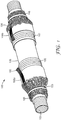
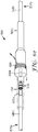
- Fig. 1 is a perspective drawing of an embodiment of the provided electrical cable splicing assembly.
- Cable splicing assembly 100 depicts an expanded or "pre-shrunk" cable splicing assembly that includes longitudinal tubular support core 102 that supports the expanded assembly during initial splicing steps.
- the support core may take any of several forms. Some embodiments of the support core include a removable support core. Examples of removable support cores can be found, for example, in PCT Publ. No. 95/11542 (Nakamura et al. ), U.S. Pat. Nos. 3,515,798 (Sievert ), 4,503,105 (Tomioka ), 4,935,464 (Ona et al.
- the support core can be a spirally wound support core such as is described, for example, in U.S. Pat. Nos. 3,515,798 (Sievert ), 4,389,440 (Keith ), or 5,589,667 (Tzukazaki et al. ).
- the support core can also include a crushable support core such as a frangible support that is not to be removed from the splice.
- the crushable support core shrinks in diameter in response to an operator crushing the frangible sections of the crushable support core, as understood by those skilled in the art.
- Examples of crushable cores can include a material that has a mesh pattern that is embedded with mastic, and the connections in the mesh of the crushable core can break responsive to compression by an operator, thereby causing the crushable core to shrink in diameter.
- Cable splicing assembly 100 in Fig. 1 also includes longitudinal conductive shield sock 104 that is configured to circumferentially surround splice body 106.
- Shield sock 104 has ends (not shown), which are typically unfinished and ragged, that are located beneath tubular cold shrink jacket 108 between the cold shrink jacket 108 and the support core 102, more particularly between cold shrink jacket 108 and splice body 106, as shown.
- the cold shrink jacket 108 illustrated in Fig. 1 includes ends 108a and 108b that are folded back toward the center of the assembly and supported by separate support cores 150.
- shield sock 104 are folded back over ends 108a and 108b and secured with securing means 155, which may comprise tape, a rubber band, or any other suitable material.
- Cable splicing assembly 100 can optionally include ground braid 160.
- Ground braid 160 extends through cable splicing assembly 100 adjacent to shield sock 104 and extends beyond cold shrink jacket 108 after the splice has been completed.
- Ground braid 160 may be connected to an external ground wire or cable.
- Ground braid 160 may be a metal braid material or any other material suitable for use as a grounding means.
- All of the embodiments of the provided assembly include a tubular cold shrink jacket.
- the cold shrink jacket is made of cold shrinkable material.
- the cold shrink jacket may comprise one or more overlapping or abutting sheets of cold shrink material.
- Cold shrinkable material can be any material of tubular character that is capable of being held in an expanded state by a support structure and which shrinks in diameter when the support structure is removed from the cold shrinkable material.
- the cold shrinkable material can be made from a rubber material, a thermoplastic elastomer, or other suitable material demonstrating cold shrink properties (such as being capable of elongation greater than 100% and permanent set less than 30%), as understood by those skilled in the art.
- suitable rubber materials include, but are not limited to, silicone rubber, EPDM (ethylenepropylene-diene copolymer), polyisoprene, styrene-butadiene rubber, polychloroprene, butyl rubber, acrylonitrile-butadiene (NBR) rubber, hydrogenated acrylonitrile-butadiene rubber, acrylic rubber, ethylene acrylic rubber, rubber material having fluoroelastomer fillers, or rubber material having epichlorohydrin fillers.
- EPDM ethylenepropylene-diene copolymer
- polyisoprene polyisoprene
- styrene-butadiene rubber polychloroprene
- butyl rubber acrylonitrile-butadiene (NBR) rubber
- hydrogenated acrylonitrile-butadiene rubber acrylic rubber, ethylene acrylic rubber, rubber material having fluoroelastomer fillers, or rubber material having epichlorohydrin fillers.
- thermoplastic elastomers include, but are not limited to, plastic materials, fluoroelastomers, epichlorohydrins, olefin thermoplastic elastomers, styrene thermoplastic elastomers such as SBS (styrene-butadiene block copolymers), and SEBS (styrene-ethylene butylene-styrene copolymers).
- SBS styrene-butadiene block copolymers
- SEBS styrene-ethylene butylene-styrene copolymers
- additives, agents, and/or fillers may be included such as, for example, coloring agents, flame retardants, lubricants, processing aides, fillers, softening agents, antistatic agents, crosslinking agents, crosslinking aides in proper amounts.
- Embodiments of the cold shrinkable material can exhibit desirable characteristics of good tear strength, heat resistance, fluid resistance, transparency, and other features as understood by those skilled in the art.
- the cold shrinkable material when in a relaxed state before installation, typically has an inner diameter that is less than the outer diameter of the splice body and the support core and also that is less than or substantially equal to at least a portion of the electrical splice to which it is to be applied, as understood by those skilled in the art. Examples and descriptions of cold shrinkable materials useful in the provided articles can be found, for example, in U.S. Pat. Nos. 5,365,020 (Vallauri et al. ) and 6,838,512 (Eggers et al. ), and U.S. Pat. Publ. No. 2008/0135288 (Taylor et al. ), and WO 2009/085445 (Janulis et al. ).
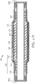
- Fig. 2A is a cross-sectional drawing of an embodiment of a cable splice assembly of the present invention.
- Cable splice assembly 200 includes tubular support core 202 defining a hollow tube through which one or more electric cables (not shown) can be inserted before splicing.
- Circumferentially surrounding the support core is splice body 206 that, in the illustrated embodiment, actually has at least three components-a semiconducting layer 210, insulative layer 212, and second semiconducting layer 214.
- the splice body 206 can be surrounded, for at least part of its longitudinal length, with a protective wrap 216.
- the splice body can be made from polymers, typically, rubbers, such as ethylene propylene diene rubbers and silicone rubbers, epoxies, epichlorohydrins, fluoroelastomers, and combinations thereof.
- Fig. 2A also illustrates features of shield sock 204.
- Shield sock 204 is located between expanded cold shrink jacket 208 and splice body 206.
- shield sock 204 is made of a conductive continuous wire mesh, screen, or braid material that, when unfolded, is longer than twice the longitudinal length of the splice body 206 (collectively 210, 212, and 214) and the expanded cold shrink jacket 208.
- the double layer shield sock is designed to carry between about 16% and about 100% of the current of the conductive cores of the cables connected by the splice.
- the ends of the material from which the shield sock is made are typically unfinished and ragged-that is they have exposed wire edges such as those that are obtained when a wire screen is cut.
- the shield sock has edges that are located underneath the expanded tubular cold shrink jacket.
- the conductive shield sock does not form a completely overlapping layer such that at least a double layer over the entire length of the splice body is formed, but instead may form a partially overlapping layer such that a double layer is formed over less than about 50% of the splice body, may form a substantially overlapping layer such that a double layer is formed over about 50% and up to about 100% of the splice body, or may form a completely overlapping double layer such that a double layer is formed over 100% or more of the splice body.
- all ends of any shield sock sections overlap each other so that complete overlapping is achieved and there are at least two layers of conductive material along the entire length of the completed splice.
- shield sock 204 has two ends 205 underneath expanded tubular cold shrink jacket 208 and two folds 205a and 205b that extend out beyond tubular cold shrink jacket 208.
- Fig. 2B shows an assembly similar to that in Fig. 2A , but having an alternate embodiment of a conductive shield sock comprising two flat shield sock sections 204', both located circumferentially around the splice body, and two folded shield sock sections 204", each located around an end of the splice body.
- Fig. 2B shows an assembly similar to that in Fig. 2A , but having an alternate embodiment of a conductive shield sock comprising two flat shield sock sections 204', both located circumferentially around the splice body, and two folded shield sock sections 204", each located around an end of the splice body.
- the ends of flat shield sock sections 204' and the ends of folded shield sock sections 204" overlap each other so that at two locations in the
- FIG. 2A shows a cross-sectional representation of a folded back cold shrink jacket, as illustrated in Fig. 1 . Ends 208a and 208b are each supported by a support core 250.
- a conductive shield sock is also suitable for this invention. Typically complete overlap is preferred, but there may be instances in which only partial or substantial overlap is preferred.
- the conductive shield sock may be a single piece of material that has two folded portions extending beyond the splice body but is shorter than the conductive shield sock shown in Fig. 2A so that its two ends do not overlap. In such an embodiment, a portion of the splice body would be covered by only a single layer of the conductive shield sock.
- This embodiment could be modified with the addition of a flat shield sock section (such as 204' shown in Fig.
- the conductive shield sock may be made of three sections, similar to the embodiment shown in Fig. 2B , but with one of the flat shield sock layers 204' removed.
- the conductive shield sock of the present invention has no exposed ragged edges, which facilitates handling in field applications.
- thinner gauge wire mesh can be used to make the shield sock. Suitable gauges for the individual strands of the wire mesh typically range from about 24 AWG to about 36 AWG. This can provide a splice which is more flexible and bendable than the current state of the art.
- the double layer shield sock can provide the same, or better, current carrying capacity (ampacity) as traditional splices, which typically have shield socks made of a single layer of thick gauge wire mesh.
- the double layer sock can provide ampacity up to about 1/3 neutral on a 750 Aluminum conductor cable. It can provide up to about 156,340 circular mil area of copper.
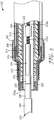
- FIG. 3 shows electrical cable splice 300 that includes an assembly and an apparatus (in this embodiment, electrical cables joined using a connector inside of the expanded assembly).
- the assembly includes tubular support core 302 defining a hollow tube in which the first conductive core 332a of first electrical cable 320 and the second conductive core of the second electrical cable (only conductive core 332b of the second electrical cable is shown) are joined by connector 330.
- the assembly also includes a splice body (layers 310, 312, and 314 in Fig.
- Connector 330 can be any connector used for physically and electrically joining two or more electrically conductive cores, such as a crimped connector or a shear bolt.
- the connector is made of aluminum, copper, or an alloy of aluminum/copper. Each wire or cable to be connected is inserted into the connector and then the connector is secured to the cable to complete the connection. Connectors useful in articles of this disclosure are well known by those skilled in the art.
- a splice body Circumferentially surrounding the support core is a splice body that, in the illustrated embodiment, actually has at least three components - a semiconducting layer 310, insulative layer 312, and second semiconducting layer 314.
- the splice body is surrounded, for at least part of its longitudinal length, with protective wrap 316.
- Constituents of the first electrical cable 320 are illustrated in Fig. 3 and include conductive core 332a, core insulation 334, semiconductive layer 336, metallic shield 338, and cable jacket 340.
- First electrical cable 320 is positioned within the assembly so that upon removal of support core 302, shield sock section 304", which includes fold 305a, can make contact with metallic shield 338of the first electrical cable.
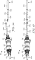
- Fig. 4 is a cross-sectional view of assembly 400 which is the same assembly as 300 except that in Fig. 4 , the inner support core has been removed and cold shrink jacket 408 has been allowed to relax (except for the ends supported by support core 450) and cause the splice body to fit snugly over the joined conductive cores of the cables.
- Fig. 4 shows an apparatus that comprises connector 430 that joins conductive core 432a of first electrical cable 420 with conductive core 432b of second electrical cable (only conductive core shown in illustration).
- Assembly 400 is now in its (substantially) relaxed state and includes the splice body (including semiconducting layer 410, insulative layer 412, and second semiconducting layer 414) snugly positioned around core insulation 434 and the joined cables.
- shield sock section 404" has been made to electrically contact first metallic shield 438 of first electrical cable 420.
- the electrical connection is secured by the use of one or more of clamp(s) 448, which may be a constant force spring, thus first metallic shield 438 of first cable 420 is now in electrical contact with metal shield sock 404 and (the other end is the same) also in electrical contact with the metallic shield 438 of the second electrical cable.
- Semiconductive layer 436 and cable jacket 440 are shown on first electrical cable 420.
- Provided electrical splice connectors can be configured to electrically connect conductors/wires having a wide range of conductor sizes.
- an electrical splice connector is provided that electrically connects medium and high voltage conductors, such as medium voltage wires (cables) having a size ranging from 2 gauge to 2500 kcmil or larger.
- Some embodiments provide an electrical splice connector suited for electrically connecting telecom, automotive, or industrial-sized conductors.
- the metallic shields and the shield sock of the provided splice can provide a conduit for the return flow of current that is conducted through the conductive cores of the cables.
- a second core can be present for return flow and the conductive pathway provided through the connected metallic shields and the shield sock of the provided splice can be used for grounding only.
- first electrical cable 520a having first conductive core 532a and first metallic shield 538a.
- First electrical cable 520a also includes core insulator 534a, semiconductor layer 536a and cable jacket 540a.
- electrical splicing assembly 500 that includes a support core 502, splice body 506, shield sock 504, cold shrink jacket 508, and support cores 550.
- the shield sock 504 has ends (not visible) that are located between cold shrink jacket 508 and the splice body 506.
- first electric cable 520a has been inserted through support core 502 of assembly 500.
- Assembly 500 has been moved in the direction of the arrow onto first electric cable 520a and away from the end to be spliced.
- electrical connector 530 is placed on conductive core 532a of first electrical cable 520a and conductive core 532b of second electrical cable 520b to establish an electrical connection.
- Electrical splicing assembly 500 is then moved in the direction of the arrow in Fig. 5b into a position so as to cover electrical connector 530 resulting in the position of the assembly and the connector shown in Fig. 5c .
- Fig. 5b electrical connector 530 is placed on conductive core 532a of first electrical cable 520a and conductive core 532b of second electrical cable 520b to establish an electrical connection.
- Electrical splicing assembly 500 is then moved in the direction of the arrow in Fig. 5b into a position so as to cover electrical connector 530 resulting in the position of the assembly and the connector shown in Fig. 5c .
- shield sock 504 is now substantially aligned over first metallic shield 538a of first electrical cable 520a on the left side of the assembly and over second metallic shield 538b of second electrical cable 520b on the right side of the assembly.
- Semiconducting layer 536b of second electrical cable 520b and connector 530 are shown in hidden view inside of the assembly in Fig. 5c .
- support core 502 is a spirally wound support core, one end 503 of which is protruding from the assembly in Fig. 5c . End 503 of support core 502 will be unwound, typically counterclockwise, and pulled in the direction of the arrow to collapse splice body 506 and the interior portion of cold shrink jacket 508 onto the spliced cables.
- clamps 548 which may be constant force springs, have been used to form an electrical connection between shield sock 504 and second metallic shield 538b. End 503 of the support core has been partially pulled out thereby collapsing a portion of the splice body 506, the shield sock 504 and an interior portion of the cold shrink jacket 508 onto second electrical cable 520b. As illustrated in Fig. 5e , after the support core 502 is completely removed, clamps 548 are used to form an electrical connection between the first metallic shield 538a of first electrical cable 520a and shield sock 504. As further illustrated in Fig.
- the support core 550 supporting cold shrink jacket end 508b has been removed and end 508b has been unfolded to fully cover shield sock 504, clamps 548, and a portion of cable jacket 540b.
- the remaining support core 550 will be removed and cold shrink jacket end 508a will be unfolded to fully cover shield sock 504, clamps 548, and a portion of cable jacket 540a.
- grease is applied under the folded back ends 508a and 508b so they can be more easily unfolded.
- a cold shrink jacket such as illustrated in Fig.
- FIG. 2A which does not have folded back ends (e.g., 108a and 108b) separate short cold shrink jackets (having their own support cores) may additionally be used.
- the cold shrink jacket of Fig. 2A would leave portions of the shield sock 204 exposed after the splice is completed.
- a cold shrink short jacket (not shown) can be positioned over the portion of shield sock 204 extending beyond cold shrink jacket 208.
- the cold shrink short jacket can be used to cover all of the exposed conductive parts of a splice after the splice is made and after the cold shrink jacket has been relaxed or shrunk.
- the cold shrink short jacket can be made of the same materials as the cold shrink jacket of the assembly.
- the cold shrink short jacket with support core is threaded onto the electrical cable before the splice is made. It is then moved over the exposed conductive parts of the splice that include the one or more clamps. The support core of the cold shrink short jacket is removed and the short jacket contracts or shrinks to complete the splice and in this way provides an environmental seal over all the conductive parts of the splice.
- kits that includes an assembly as described above.
- the kit includes at least one clamp, typically two clamps, for each side of the splice, and optionally, depending on the type of cold shrink jacket used, a cold shrink short jacket.
Landscapes
- Engineering & Computer Science (AREA)
- Architecture (AREA)
- Civil Engineering (AREA)
- Structural Engineering (AREA)
- Cable Accessories (AREA)
- Shielding Devices Or Components To Electric Or Magnetic Fields (AREA)
- Connections Effected By Soldering, Adhesion, Or Permanent Deformation (AREA)
Claims (2)
- Anordnung (200; 300), umfassend:einen röhrenförmigen Trägerkern (202; 302);einen Spleißkörper (206; 210, 212, 214; 310, 312, 314), der zwei Enden aufweist und auf dem Trägerkern angeordnet ist;einen leitfähigen Abschirmstrumpf (204; 204', 204"; 304', 304"), der mindestens zwei überlappende Schichten umfasst, und der so konfiguriert ist, dass er den Spleißkörper (206; 210, 212, 214; 310, 312, 314) umlaufend umgibt; undeinen Kaltschrumpfmantel (208; 308), der so konfiguriert ist, dass er den Abschirmstrumpf (204; 204', 204"; 304', 304") umlaufend umgibt,wobei der leitfähige Abschirmstrumpf (204; 204', 204"; 304', 304") sich über beide Enden des Spleißkörpers (206; 210, 212, 214; 310, 312, 314) hinaus erstreckt, wobei der leitfähige Abschirmstrumpf (204; 204', 204"; 304', 304") einen oder mehrere Abschnitte umfasst, wobei jeder Abschnitt zwei Enden aufweist, und wobei alle der Abschnittsenden zwischen dem Kaltschrumpfmantel (208; 308) und dem Spleißkörper (206; 210, 212, 214; 310, 312, 314) angeordnet sind; undwobei mindestens ein Abschnitt des Abschirmstrumpfs (204; 204', 204"; 304', 304") einen gefalteten Abschnitt umfasst, der sich über ein Ende des Spleißkörpers (206; 210, 212, 214; 310, 312, 314) hinaus erstreckt.
- Gegenstand, umfassend:eine Vorrichtung; undeine Anordnung (200; 300), umfassend:einen Spleißkörper (206; 210, 212, 214; 310, 312, 314) mit zwei Enden,einen longitudinalen leitfähigen Abschirmstrumpf (204; 204', 204"; 304', 304"), der mindestens zwei überlappende Schichten umfasst, und der so konfiguriert ist, dass er den Spleißkörper (206; 210, 212, 214; 310, 312, 314) umlaufend umgibt, undeinen röhrenförmigen Kaltschrumpfmantel (208; 308), der so konfiguriert ist, dass er den Abschirmstrumpf (204; 204', 204"; 304', 304") umlaufend umgibt,wobei der leitfähige Abschirmstrumpf (204; 204', 204"; 304', 304") sich über beide Enden des Spleißkörpers (206; 210, 212, 214; 310, 312, 314) hinaus erstreckt,wobei der leitfähige Abschirmstrumpf (204; 204', 204"; 304', 304") einen oder mehrere Abschnitte umfasst, wobei jeder Abschnitt zwei Enden aufweist, und wobei alle der Abschnittsenden zwischen dem Kaltschrumpfmantel (208; 308) und dem Spleißkörper (206; 210, 212, 214; 310, 312, 314) angeordnet sind; undwobei mindestens ein Abschnitt des Abschirmstrumpfs (204; 204', 204"; 304', 304") einen gefalteten Abschnitt umfasst, der sich über ein Ende des Spleißkörpers (206; 210, 212, 214; 310, 312, 314) hinaus erstreckt, undwobei der Spleißkörper (206; 210, 212, 214; 310, 312, 314), der Abschirmstrumpf (204; 204', 204"; 304', 304") und der Kaltschrumpfmantel (208; 308) zusammen so konfiguriert sind, dass sie die Vorrichtung umlaufend umgeben.
Applications Claiming Priority (2)
| Application Number | Priority Date | Filing Date | Title |
|---|---|---|---|
| US15004709P | 2009-02-05 | 2009-02-05 | |
| PCT/US2010/022895 WO2010091017A1 (en) | 2009-02-05 | 2010-02-02 | Splice assembly with shield sock |
Publications (3)
| Publication Number | Publication Date |
|---|---|
| EP2394337A1 EP2394337A1 (de) | 2011-12-14 |
| EP2394337A4 EP2394337A4 (de) | 2014-08-06 |
| EP2394337B1 true EP2394337B1 (de) | 2017-04-05 |
Family
ID=42396768
Family Applications (1)
| Application Number | Title | Priority Date | Filing Date |
|---|---|---|---|
| EP10739022.1A Active EP2394337B1 (de) | 2009-02-05 | 2010-02-02 | Spleissanordnung mit schutzstrumpf |
Country Status (12)
| Country | Link |
|---|---|
| US (1) | US8445783B2 (de) |
| EP (1) | EP2394337B1 (de) |
| JP (1) | JP5698681B2 (de) |
| KR (1) | KR101708072B1 (de) |
| CN (1) | CN102308448B (de) |
| BR (1) | BRPI1005347B1 (de) |
| CA (1) | CA2751451C (de) |
| ES (1) | ES2628305T3 (de) |
| MX (1) | MX2011008140A (de) |
| RU (1) | RU2493643C2 (de) |
| TW (1) | TWI491121B (de) |
| WO (1) | WO2010091017A1 (de) |
Families Citing this family (26)
| Publication number | Priority date | Publication date | Assignee | Title |
|---|---|---|---|---|
| BRPI0419163B1 (pt) * | 2004-10-27 | 2021-10-13 | Prysmian Cavi E Sistemi Energia S.R.L | Método e dispositivo para revestir a área de junção entre pelo menos dois elementos alongados, e, junta para cabos elétricos |
| AU2010366147B2 (en) | 2010-12-22 | 2016-08-04 | Prysmian S.P.A. | Screen connector for electrical cables and jointing assembly comprising said screen connector |
| US9059581B2 (en) * | 2011-04-28 | 2015-06-16 | Richards Manufacturing Company, A New Jersey Limited Partnership | Cold shrinkable primary joint |
| JP2014017181A (ja) * | 2012-07-11 | 2014-01-30 | Tyco Electronics Japan Kk | シールドケーブルハーネスの端末構造およびその製造方法 |
| US20140057103A1 (en) * | 2012-08-24 | 2014-02-27 | Samson Rope Technologies | Line Systems and Methods and Chafe Jackets Therefor |
| TWI455153B (zh) * | 2012-09-27 | 2014-10-01 | Wistron Corp | 電線組件 |
| US9202612B2 (en) * | 2012-09-28 | 2015-12-01 | Thomas & Betts International, Llc | Cold shrink assembly |
| CN103715647A (zh) | 2012-10-09 | 2014-04-09 | 泰科电子(上海)有限公司 | 用于电力电缆的冷缩式终端 |
| WO2014070851A1 (en) | 2012-10-31 | 2014-05-08 | Delphi Technologies, Inc. | Device and method for splicing shielded wire cables |
| US9543747B2 (en) | 2013-10-30 | 2017-01-10 | Delphi Technologies, Inc. | Method for splicing shielded wire cables |
| US9504195B2 (en) | 2014-05-16 | 2016-11-22 | Tyco Electronics Corporation | Cover assemblies, kits and methods for covering electrical cables and connections |
| JP6566613B2 (ja) * | 2014-07-28 | 2019-08-28 | スリーエム イノベイティブ プロパティズ カンパニー | 被覆処理具、及び被覆処理方法 |
| CN105529564A (zh) * | 2016-02-29 | 2016-04-27 | 孙萍 | 分体式防水快速连接器 |
| JP6614026B2 (ja) * | 2016-05-20 | 2019-12-04 | 株式会社オートネットワーク技術研究所 | 電磁シールド部材、配線モジュール及び電磁シールド部材の製造方法 |
| US10862289B2 (en) | 2016-11-03 | 2020-12-08 | Hubbell Incorporated | Flexible cable splice |
| EP3545596B1 (de) | 2016-11-22 | 2021-05-26 | TE Connectivity Corporation | Umschliessungen von kabeln und elektrische verbindungen sowie vorgedehnte einheit und verfahren mit denselben |
| WO2018163018A2 (en) * | 2017-03-10 | 2018-09-13 | 3M Innovative Properties Company | Cover assembly with hybrid core structure |
| US10283878B2 (en) * | 2017-09-13 | 2019-05-07 | Te Connectivity Corporation | Neutral conductor connection protection devices and cover assembly kits, electrical connections and methods including same |
| CN107769147B (zh) * | 2017-11-21 | 2020-02-07 | 安徽伊法拉电气有限公司 | 一种35kv冷缩接头 |
| EP3803103A1 (de) * | 2018-05-28 | 2021-04-14 | LM Wind Power International Technology II ApS | Verbindungselement für blitzschutzsystem einer windturbinenschaufel |
| US10998651B2 (en) | 2019-05-22 | 2021-05-04 | Nvent Services Gmbh | Flame-resistant heat shrink assemblies for trace heating cables |
| RU197160U1 (ru) * | 2019-10-07 | 2020-04-08 | Акционерное общество "Военно-промышленная корпорация "Научно-производственное объединение машиностроения" | Обжимной переходной экранированный контакт для сращивания электрических цепей |
| US11424608B2 (en) | 2020-02-18 | 2022-08-23 | Nvent Services Gmbh | Devices and methods for electrical cable splices |
| US11303049B2 (en) | 2020-07-09 | 2022-04-12 | TE Connectivity Services Gmbh | Cable neutral wires connectors and methods and connections including same |
| EP4002619A1 (de) * | 2020-11-12 | 2022-05-25 | Nexans | Verstärkte wasserbarriere über einer muffe |
| US11888278B2 (en) | 2021-03-24 | 2024-01-30 | Richards Mfg. Co. | Cold shrink core |
Family Cites Families (41)
| Publication number | Priority date | Publication date | Assignee | Title |
|---|---|---|---|---|
| US3515798A (en) | 1968-12-06 | 1970-06-02 | Minnesota Mining & Mfg | Elastic cover and removable cone assembly |
| US3717717A (en) * | 1970-04-20 | 1973-02-20 | Joslyn Mfg & Supply Co | Shrinkable cable joint sleeve, cable joint employing the same, and method of forming a cable joint |
| SU995168A1 (ru) * | 1980-07-21 | 1983-02-07 | Предприятие П/Я А-3759 | Узел электрического соединени двухпроводных электрических цепей |
| US4389440A (en) | 1982-02-08 | 1983-06-21 | Minnesota Mining & Manufacturing Company | Torque preloaded elastic cover for torque coupling |
| JPS59121172U (ja) | 1983-02-04 | 1984-08-15 | ミネソタ・マイニング・アンド・マニユフアクチユアリング・コンパニ− | ケーブル電線被覆の剥離部分のカバー装置 |
| SU1495890A1 (ru) * | 1986-12-29 | 1989-07-23 | Всесоюзный научно-исследовательский институт электромеханики | Узел соединени коаксиальных кабелей |
| US4935464A (en) | 1987-04-30 | 1990-06-19 | Toray Silicone Company Limited | Organopolysiloxane microemulsion, process for its production and application thereof |
| SU1612346A1 (ru) * | 1988-03-09 | 1990-12-07 | Предприятие П/Я В-2962 | Способ сращивани экранированных кабелей |
| IT1230014B (it) * | 1989-04-20 | 1991-09-20 | Pirelli Cavi Spa | Rivestimento per giunti di cavi, elemento diun dispositivo per realizzare giunti di cavi e giunto di cavi incorporante tale rivestimento. |
| US5365020A (en) * | 1989-04-20 | 1994-11-15 | Pirelli Cavi S.P.A. | Cable joint coverings, devices for applying such coverings and joints obtained therewith |
| IT1229366B (it) | 1989-05-24 | 1991-08-08 | Pirelli Cavi Spa | Complesso costituito da un manicotto, calzato su un supporto tubolare, particolarmente per giunti e terminali di cavi elettrici. |
| AU6219890A (en) * | 1989-10-16 | 1991-04-18 | Minnesota Mining And Manufacturing Company | Elastomeric covering having conformable interior |
| US5098752A (en) * | 1990-04-17 | 1992-03-24 | Raychem Corporation | Recoverable elastomeric sleeve and method for installation and use |
| US5061208A (en) | 1990-08-27 | 1991-10-29 | Molex Incorporated | Conductive shell for clamping onto a shielded electrical connector |
| CA2059007C (en) | 1991-02-19 | 1996-05-14 | William H. Tuggle, Jr. | Removable core for a shrinkable tubular sheath and method and apparatus for producing same |
| IT1252219B (it) * | 1991-12-16 | 1995-06-05 | Pirelli Cavi Spa | Complesso di rivestimento di elementi cilindrici allungati quali giunti di cavi elettrici. |
| US5589667A (en) | 1992-04-28 | 1996-12-31 | Minnesota Mining And Manufacturing Company | Removable core for pre-stretched tube |
| DE4319299C1 (de) | 1993-06-10 | 1994-06-09 | Bizerba Werke Kraut Kg Wilh | Wägevorrichtung für den Kassenplatz eines Ladengeschäfts |
| FR2706979B1 (de) | 1993-06-25 | 1995-09-22 | Euromold | |
| JP3359959B2 (ja) | 1993-10-21 | 2002-12-24 | ミネソタ マイニング アンド マニュファクチャリング カンパニー | 被覆装置 |
| US5756936A (en) | 1994-05-18 | 1998-05-26 | Minnesota Mining And Manufacturing Company | Cylindrical radially shrinkable sleeve for an electrical cable and composition thereof |
| FR2724444B1 (fr) | 1994-09-14 | 1996-11-22 | Alcatel Cable | Support de pose d'un manchon retractable |
| FR2736218B1 (fr) | 1995-06-27 | 1997-08-01 | Alcatel Cable | Jonction de cables de puissance |
| US5801332A (en) * | 1995-08-31 | 1998-09-01 | Minnesota Mining And Manufacturing Company | Elastically recoverable silicone splice cover |
| EP0845845B1 (de) * | 1996-11-29 | 2003-07-09 | Nexans | Kaltschrumpfbare Schutzmuffe für Kabelverbindungen |
| JP3879073B2 (ja) | 1997-03-13 | 2007-02-07 | スリーエム カンパニー | 小型被覆装置 |
| WO1999021259A1 (en) | 1997-10-22 | 1999-04-29 | Minnesota Mining And Manufacturing Company | Improved medium voltage branch splice and method of making the same |
| US6103975A (en) * | 1998-06-29 | 2000-08-15 | 3M Innovative Properties Company | Pre-assembled electrical splice component |
| US6080101A (en) | 1998-08-26 | 2000-06-27 | Olympus Optical Co. Ltd. | Endoscope video camera head which can be autoclaved |
| JP4403569B2 (ja) * | 1999-11-12 | 2010-01-27 | 住電朝日精工株式会社 | ケーブル接続部の組み立て方法およびケーブル接続部材 |
| EP1195872B1 (de) * | 2000-10-05 | 2004-03-03 | Nexans | Kabelverbindung mit verbesserter Verbindung für Abschirmung |
| US20040262025A1 (en) | 2001-09-21 | 2004-12-30 | Konrad Brandt | Multi-part insulating cover |
| WO2003028182A1 (en) | 2001-09-21 | 2003-04-03 | 3M Innovative Properties Company | Multi-part insulating cover |
| RU2319056C2 (ru) * | 2002-08-28 | 2008-03-10 | ТиВиСи Коммьюникейшнз | Конструкция удлиненного рукава для кабельного канала |
| US6838512B2 (en) | 2003-06-05 | 2005-01-04 | 3M Innovative Properties Company | Cold shrink fluoroelastomeric article |
| ES2313023T3 (es) | 2004-06-25 | 2009-03-01 | Prysmian S.P.A. | Metodo de recubrimiento de un objeto alargado y dispositivo para recubrir el susodicho objeto alargado. |
| US7351908B2 (en) | 2006-08-18 | 2008-04-01 | 3M Innovative Properties Company | Electrical power cable adaptor and method of use |
| US7511222B2 (en) | 2006-12-11 | 2009-03-31 | 3M Innovative Properties Company | Cold shrink article and method of using cold shrink article |
| US7863521B2 (en) | 2006-12-11 | 2011-01-04 | 3M Innovative Properties Company | Cold shrink article and method of using cold shrink article |
| US7670197B2 (en) | 2007-12-20 | 2010-03-02 | 3M Innovative Properties Company | Electrical splice connector |
| US7476114B1 (en) * | 2008-05-05 | 2009-01-13 | Tyco Electronics Corporation | Cover assemblies for cables and electrical connections and methods for making and using the same |
-
2010
- 2010-02-02 CA CA2751451A patent/CA2751451C/en active Active
- 2010-02-02 EP EP10739022.1A patent/EP2394337B1/de active Active
- 2010-02-02 ES ES10739022.1T patent/ES2628305T3/es active Active
- 2010-02-02 CN CN201080006864.4A patent/CN102308448B/zh active Active
- 2010-02-02 JP JP2011549215A patent/JP5698681B2/ja not_active Expired - Fee Related
- 2010-02-02 KR KR1020117020475A patent/KR101708072B1/ko active IP Right Grant
- 2010-02-02 BR BRPI1005347-6A patent/BRPI1005347B1/pt active IP Right Grant
- 2010-02-02 WO PCT/US2010/022895 patent/WO2010091017A1/en active Application Filing
- 2010-02-02 MX MX2011008140A patent/MX2011008140A/es active IP Right Grant
- 2010-02-02 US US12/698,791 patent/US8445783B2/en active Active
- 2010-02-02 RU RU2011132261/07A patent/RU2493643C2/ru not_active IP Right Cessation
- 2010-02-04 TW TW099103372A patent/TWI491121B/zh not_active IP Right Cessation
Also Published As
| Publication number | Publication date |
|---|---|
| EP2394337A1 (de) | 2011-12-14 |
| CN102308448A (zh) | 2012-01-04 |
| BRPI1005347A2 (pt) | 2020-08-18 |
| EP2394337A4 (de) | 2014-08-06 |
| RU2011132261A (ru) | 2013-03-10 |
| ES2628305T3 (es) | 2017-08-02 |
| US8445783B2 (en) | 2013-05-21 |
| JP2012517212A (ja) | 2012-07-26 |
| CA2751451A1 (en) | 2010-08-12 |
| MX2011008140A (es) | 2011-08-17 |
| KR20110116200A (ko) | 2011-10-25 |
| KR101708072B1 (ko) | 2017-02-17 |
| TW201042851A (en) | 2010-12-01 |
| RU2493643C2 (ru) | 2013-09-20 |
| CA2751451C (en) | 2017-10-10 |
| WO2010091017A1 (en) | 2010-08-12 |
| BRPI1005347B1 (pt) | 2021-02-17 |
| US20100193235A1 (en) | 2010-08-05 |
| CN102308448B (zh) | 2016-08-03 |
| JP5698681B2 (ja) | 2015-04-08 |
| TWI491121B (zh) | 2015-07-01 |
Similar Documents
| Publication | Publication Date | Title |
|---|---|---|
| EP2394337B1 (de) | Spleissanordnung mit schutzstrumpf | |
| US9504195B2 (en) | Cover assemblies, kits and methods for covering electrical cables and connections | |
| US8030570B2 (en) | Cover assemblies for cables and electrical connections and methods for making and using the same | |
| RU2454767C2 (ru) | Изделие холодной усадки и способ использования изделия холодной усадки | |
| EP3350896B1 (de) | Abdeckungsanordnungen und verfahren zur abdeckung von elektrischen kabeln und verbindungen | |
| GB2099638A (en) | Improvements relating to jointing and/or terminating electric cables | |
| US10283878B2 (en) | Neutral conductor connection protection devices and cover assembly kits, electrical connections and methods including same | |
| JP4680159B2 (ja) | ゴム又はプラスチック絶縁電力ケーブル | |
| EP3545596B1 (de) | Umschliessungen von kabeln und elektrische verbindungen sowie vorgedehnte einheit und verfahren mit denselben | |
| US9590410B2 (en) | Screen connectors for electrical cables and jointing assemblies comprising the screen connector |
Legal Events
| Date | Code | Title | Description |
|---|---|---|---|
| PUAI | Public reference made under article 153(3) epc to a published international application that has entered the european phase |
Free format text: ORIGINAL CODE: 0009012 |
|
| 17P | Request for examination filed |
Effective date: 20110905 |
|
| AK | Designated contracting states |
Kind code of ref document: A1 Designated state(s): AT BE BG CH CY CZ DE DK EE ES FI FR GB GR HR HU IE IS IT LI LT LU LV MC MK MT NL NO PL PT RO SE SI SK SM TR |
|
| DAX | Request for extension of the european patent (deleted) | ||
| REG | Reference to a national code |
Ref country code: DE Ref legal event code: R079 Ref document number: 602010041301 Country of ref document: DE Free format text: PREVIOUS MAIN CLASS: H02G0003060000 Ipc: H02G0015080000 |
|
| A4 | Supplementary search report drawn up and despatched |
Effective date: 20140707 |
|
| RIC1 | Information provided on ipc code assigned before grant |
Ipc: H02G 15/18 20060101ALN20140701BHEP Ipc: H02G 15/08 20060101AFI20140701BHEP Ipc: H02G 15/103 20060101ALN20140701BHEP |
|
| 17Q | First examination report despatched |
Effective date: 20150529 |
|
| STAA | Information on the status of an ep patent application or granted ep patent |
Free format text: STATUS: EXAMINATION IS IN PROGRESS |
|
| GRAP | Despatch of communication of intention to grant a patent |
Free format text: ORIGINAL CODE: EPIDOSNIGR1 |
|
| STAA | Information on the status of an ep patent application or granted ep patent |
Free format text: STATUS: GRANT OF PATENT IS INTENDED |
|
| INTG | Intention to grant announced |
Effective date: 20161123 |
|
| RIN1 | Information on inventor provided before grant (corrected) |
Inventor name: MULVEY, KIM, P. Inventor name: TAYLOR, WILLIAM, L. Inventor name: WENTZEL, CARL, J. |
|
| GRAS | Grant fee paid |
Free format text: ORIGINAL CODE: EPIDOSNIGR3 |
|
| GRAA | (expected) grant |
Free format text: ORIGINAL CODE: 0009210 |
|
| STAA | Information on the status of an ep patent application or granted ep patent |
Free format text: STATUS: THE PATENT HAS BEEN GRANTED |
|
| AK | Designated contracting states |
Kind code of ref document: B1 Designated state(s): AT BE BG CH CY CZ DE DK EE ES FI FR GB GR HR HU IE IS IT LI LT LU LV MC MK MT NL NO PL PT RO SE SI SK SM TR |
|
| REG | Reference to a national code |
Ref country code: GB Ref legal event code: FG4D |
|
| REG | Reference to a national code |
Ref country code: CH Ref legal event code: EP |
|
| REG | Reference to a national code |
Ref country code: AT Ref legal event code: REF Ref document number: 882644 Country of ref document: AT Kind code of ref document: T Effective date: 20170415 |
|
| REG | Reference to a national code |
Ref country code: IE Ref legal event code: FG4D |
|
| REG | Reference to a national code |
Ref country code: DE Ref legal event code: R096 Ref document number: 602010041301 Country of ref document: DE |
|
| REG | Reference to a national code |
Ref country code: ES Ref legal event code: FG2A Ref document number: 2628305 Country of ref document: ES Kind code of ref document: T3 Effective date: 20170802 |
|
| REG | Reference to a national code |
Ref country code: NL Ref legal event code: MP Effective date: 20170405 |
|
| REG | Reference to a national code |
Ref country code: LT Ref legal event code: MG4D |
|
| REG | Reference to a national code |
Ref country code: AT Ref legal event code: MK05 Ref document number: 882644 Country of ref document: AT Kind code of ref document: T Effective date: 20170405 |
|
| PG25 | Lapsed in a contracting state [announced via postgrant information from national office to epo] |
Ref country code: NL Free format text: LAPSE BECAUSE OF FAILURE TO SUBMIT A TRANSLATION OF THE DESCRIPTION OR TO PAY THE FEE WITHIN THE PRESCRIBED TIME-LIMIT Effective date: 20170405 |
|
| PG25 | Lapsed in a contracting state [announced via postgrant information from national office to epo] |
Ref country code: LT Free format text: LAPSE BECAUSE OF FAILURE TO SUBMIT A TRANSLATION OF THE DESCRIPTION OR TO PAY THE FEE WITHIN THE PRESCRIBED TIME-LIMIT Effective date: 20170405 Ref country code: AT Free format text: LAPSE BECAUSE OF FAILURE TO SUBMIT A TRANSLATION OF THE DESCRIPTION OR TO PAY THE FEE WITHIN THE PRESCRIBED TIME-LIMIT Effective date: 20170405 Ref country code: FI Free format text: LAPSE BECAUSE OF FAILURE TO SUBMIT A TRANSLATION OF THE DESCRIPTION OR TO PAY THE FEE WITHIN THE PRESCRIBED TIME-LIMIT Effective date: 20170405 Ref country code: GR Free format text: LAPSE BECAUSE OF FAILURE TO SUBMIT A TRANSLATION OF THE DESCRIPTION OR TO PAY THE FEE WITHIN THE PRESCRIBED TIME-LIMIT Effective date: 20170706 Ref country code: HR Free format text: LAPSE BECAUSE OF FAILURE TO SUBMIT A TRANSLATION OF THE DESCRIPTION OR TO PAY THE FEE WITHIN THE PRESCRIBED TIME-LIMIT Effective date: 20170405 Ref country code: NO Free format text: LAPSE BECAUSE OF FAILURE TO SUBMIT A TRANSLATION OF THE DESCRIPTION OR TO PAY THE FEE WITHIN THE PRESCRIBED TIME-LIMIT Effective date: 20170705 |
|
| PG25 | Lapsed in a contracting state [announced via postgrant information from national office to epo] |
Ref country code: SE Free format text: LAPSE BECAUSE OF FAILURE TO SUBMIT A TRANSLATION OF THE DESCRIPTION OR TO PAY THE FEE WITHIN THE PRESCRIBED TIME-LIMIT Effective date: 20170405 Ref country code: IS Free format text: LAPSE BECAUSE OF FAILURE TO SUBMIT A TRANSLATION OF THE DESCRIPTION OR TO PAY THE FEE WITHIN THE PRESCRIBED TIME-LIMIT Effective date: 20170805 Ref country code: LV Free format text: LAPSE BECAUSE OF FAILURE TO SUBMIT A TRANSLATION OF THE DESCRIPTION OR TO PAY THE FEE WITHIN THE PRESCRIBED TIME-LIMIT Effective date: 20170405 Ref country code: BG Free format text: LAPSE BECAUSE OF FAILURE TO SUBMIT A TRANSLATION OF THE DESCRIPTION OR TO PAY THE FEE WITHIN THE PRESCRIBED TIME-LIMIT Effective date: 20170705 Ref country code: PL Free format text: LAPSE BECAUSE OF FAILURE TO SUBMIT A TRANSLATION OF THE DESCRIPTION OR TO PAY THE FEE WITHIN THE PRESCRIBED TIME-LIMIT Effective date: 20170405 |
|
| REG | Reference to a national code |
Ref country code: FR Ref legal event code: PLFP Year of fee payment: 9 |
|
| REG | Reference to a national code |
Ref country code: DE Ref legal event code: R097 Ref document number: 602010041301 Country of ref document: DE |
|
| PG25 | Lapsed in a contracting state [announced via postgrant information from national office to epo] |
Ref country code: DK Free format text: LAPSE BECAUSE OF FAILURE TO SUBMIT A TRANSLATION OF THE DESCRIPTION OR TO PAY THE FEE WITHIN THE PRESCRIBED TIME-LIMIT Effective date: 20170405 Ref country code: CZ Free format text: LAPSE BECAUSE OF FAILURE TO SUBMIT A TRANSLATION OF THE DESCRIPTION OR TO PAY THE FEE WITHIN THE PRESCRIBED TIME-LIMIT Effective date: 20170405 Ref country code: EE Free format text: LAPSE BECAUSE OF FAILURE TO SUBMIT A TRANSLATION OF THE DESCRIPTION OR TO PAY THE FEE WITHIN THE PRESCRIBED TIME-LIMIT Effective date: 20170405 Ref country code: SK Free format text: LAPSE BECAUSE OF FAILURE TO SUBMIT A TRANSLATION OF THE DESCRIPTION OR TO PAY THE FEE WITHIN THE PRESCRIBED TIME-LIMIT Effective date: 20170405 Ref country code: RO Free format text: LAPSE BECAUSE OF FAILURE TO SUBMIT A TRANSLATION OF THE DESCRIPTION OR TO PAY THE FEE WITHIN THE PRESCRIBED TIME-LIMIT Effective date: 20170405 |
|
| PLBE | No opposition filed within time limit |
Free format text: ORIGINAL CODE: 0009261 |
|
| STAA | Information on the status of an ep patent application or granted ep patent |
Free format text: STATUS: NO OPPOSITION FILED WITHIN TIME LIMIT |
|
| PG25 | Lapsed in a contracting state [announced via postgrant information from national office to epo] |
Ref country code: SM Free format text: LAPSE BECAUSE OF FAILURE TO SUBMIT A TRANSLATION OF THE DESCRIPTION OR TO PAY THE FEE WITHIN THE PRESCRIBED TIME-LIMIT Effective date: 20170405 |
|
| 26N | No opposition filed |
Effective date: 20180108 |
|
| PGFP | Annual fee paid to national office [announced via postgrant information from national office to epo] |
Ref country code: ES Payment date: 20180301 Year of fee payment: 9 |
|
| PG25 | Lapsed in a contracting state [announced via postgrant information from national office to epo] |
Ref country code: SI Free format text: LAPSE BECAUSE OF FAILURE TO SUBMIT A TRANSLATION OF THE DESCRIPTION OR TO PAY THE FEE WITHIN THE PRESCRIBED TIME-LIMIT Effective date: 20170405 |
|
| REG | Reference to a national code |
Ref country code: CH Ref legal event code: PL |
|
| PG25 | Lapsed in a contracting state [announced via postgrant information from national office to epo] |
Ref country code: MC Free format text: LAPSE BECAUSE OF FAILURE TO SUBMIT A TRANSLATION OF THE DESCRIPTION OR TO PAY THE FEE WITHIN THE PRESCRIBED TIME-LIMIT Effective date: 20170405 |
|
| REG | Reference to a national code |
Ref country code: IE Ref legal event code: MM4A |
|
| REG | Reference to a national code |
Ref country code: BE Ref legal event code: MM Effective date: 20180228 |
|
| PG25 | Lapsed in a contracting state [announced via postgrant information from national office to epo] |
Ref country code: CH Free format text: LAPSE BECAUSE OF NON-PAYMENT OF DUE FEES Effective date: 20180228 Ref country code: LU Free format text: LAPSE BECAUSE OF NON-PAYMENT OF DUE FEES Effective date: 20180202 Ref country code: LI Free format text: LAPSE BECAUSE OF NON-PAYMENT OF DUE FEES Effective date: 20180228 |
|
| PG25 | Lapsed in a contracting state [announced via postgrant information from national office to epo] |
Ref country code: IE Free format text: LAPSE BECAUSE OF NON-PAYMENT OF DUE FEES Effective date: 20180202 |
|
| PG25 | Lapsed in a contracting state [announced via postgrant information from national office to epo] |
Ref country code: BE Free format text: LAPSE BECAUSE OF NON-PAYMENT OF DUE FEES Effective date: 20180228 |
|
| PG25 | Lapsed in a contracting state [announced via postgrant information from national office to epo] |
Ref country code: MT Free format text: LAPSE BECAUSE OF NON-PAYMENT OF DUE FEES Effective date: 20180202 |
|
| REG | Reference to a national code |
Ref country code: ES Ref legal event code: FD2A Effective date: 20200327 |
|
| PG25 | Lapsed in a contracting state [announced via postgrant information from national office to epo] |
Ref country code: TR Free format text: LAPSE BECAUSE OF FAILURE TO SUBMIT A TRANSLATION OF THE DESCRIPTION OR TO PAY THE FEE WITHIN THE PRESCRIBED TIME-LIMIT Effective date: 20170405 |
|
| PG25 | Lapsed in a contracting state [announced via postgrant information from national office to epo] |
Ref country code: ES Free format text: LAPSE BECAUSE OF NON-PAYMENT OF DUE FEES Effective date: 20190203 |
|
| PG25 | Lapsed in a contracting state [announced via postgrant information from national office to epo] |
Ref country code: HU Free format text: LAPSE BECAUSE OF FAILURE TO SUBMIT A TRANSLATION OF THE DESCRIPTION OR TO PAY THE FEE WITHIN THE PRESCRIBED TIME-LIMIT; INVALID AB INITIO Effective date: 20100202 Ref country code: PT Free format text: LAPSE BECAUSE OF FAILURE TO SUBMIT A TRANSLATION OF THE DESCRIPTION OR TO PAY THE FEE WITHIN THE PRESCRIBED TIME-LIMIT Effective date: 20170405 |
|
| PG25 | Lapsed in a contracting state [announced via postgrant information from national office to epo] |
Ref country code: CY Free format text: LAPSE BECAUSE OF FAILURE TO SUBMIT A TRANSLATION OF THE DESCRIPTION OR TO PAY THE FEE WITHIN THE PRESCRIBED TIME-LIMIT Effective date: 20170405 Ref country code: MK Free format text: LAPSE BECAUSE OF NON-PAYMENT OF DUE FEES Effective date: 20170405 |
|
| PGFP | Annual fee paid to national office [announced via postgrant information from national office to epo] |
Ref country code: FR Payment date: 20230119 Year of fee payment: 14 |
|
| PGFP | Annual fee paid to national office [announced via postgrant information from national office to epo] |
Ref country code: IT Payment date: 20230120 Year of fee payment: 14 |
|
| P01 | Opt-out of the competence of the unified patent court (upc) registered |
Effective date: 20230530 |
|
| PGFP | Annual fee paid to national office [announced via postgrant information from national office to epo] |
Ref country code: DE Payment date: 20240123 Year of fee payment: 15 Ref country code: GB Payment date: 20240123 Year of fee payment: 15 |