EP2394319B1 - Multiply-conductive matrix for battery current collectors - Google Patents
Multiply-conductive matrix for battery current collectors Download PDFInfo
- Publication number
- EP2394319B1 EP2394319B1 EP10738170.9A EP10738170A EP2394319B1 EP 2394319 B1 EP2394319 B1 EP 2394319B1 EP 10738170 A EP10738170 A EP 10738170A EP 2394319 B1 EP2394319 B1 EP 2394319B1
- Authority
- EP
- European Patent Office
- Prior art keywords
- region
- matrix
- frame
- mcm
- specific surface
- Prior art date
- Legal status (The legal status is an assumption and is not a legal conclusion. Google has not performed a legal analysis and makes no representation as to the accuracy of the status listed.)
- Active
Links
- 239000011159 matrix material Substances 0.000 title claims description 121
- 238000000034 method Methods 0.000 claims description 48
- 239000000758 substrate Substances 0.000 claims description 37
- VNWKTOKETHGBQD-UHFFFAOYSA-N methane Chemical compound C VNWKTOKETHGBQD-UHFFFAOYSA-N 0.000 claims description 17
- 239000000126 substance Substances 0.000 claims description 15
- 239000011248 coating agent Substances 0.000 claims description 13
- 238000000576 coating method Methods 0.000 claims description 13
- 210000000746 body region Anatomy 0.000 claims description 11
- 239000000463 material Substances 0.000 claims description 11
- 239000011148 porous material Substances 0.000 claims description 9
- 238000005520 cutting process Methods 0.000 claims description 8
- 238000004519 manufacturing process Methods 0.000 claims description 8
- 238000005304 joining Methods 0.000 claims description 3
- 229920000642 polymer Polymers 0.000 claims description 3
- 229920005830 Polyurethane Foam Polymers 0.000 claims description 2
- 239000011496 polyurethane foam Substances 0.000 claims description 2
- PXHVJJICTQNCMI-UHFFFAOYSA-N nickel Substances [Ni] PXHVJJICTQNCMI-UHFFFAOYSA-N 0.000 description 27
- 239000002253 acid Substances 0.000 description 18
- 239000004020 conductor Substances 0.000 description 15
- 229910052759 nickel Inorganic materials 0.000 description 14
- 229910052751 metal Inorganic materials 0.000 description 13
- 239000002184 metal Substances 0.000 description 13
- 239000000243 solution Substances 0.000 description 12
- HBBGRARXTFLTSG-UHFFFAOYSA-N Lithium ion Chemical compound [Li+] HBBGRARXTFLTSG-UHFFFAOYSA-N 0.000 description 8
- 229910001416 lithium ion Inorganic materials 0.000 description 8
- 230000008901 benefit Effects 0.000 description 7
- 230000008569 process Effects 0.000 description 7
- 229910000978 Pb alloy Inorganic materials 0.000 description 6
- XPFVYQJUAUNWIW-UHFFFAOYSA-N furfuryl alcohol Chemical compound OCC1=CC=CO1 XPFVYQJUAUNWIW-UHFFFAOYSA-N 0.000 description 6
- 229910001092 metal group alloy Inorganic materials 0.000 description 6
- 239000000203 mixture Substances 0.000 description 6
- OKTJSMMVPCPJKN-UHFFFAOYSA-N Carbon Chemical compound [C] OKTJSMMVPCPJKN-UHFFFAOYSA-N 0.000 description 5
- 238000009713 electroplating Methods 0.000 description 5
- 230000001965 increasing effect Effects 0.000 description 5
- BQCADISMDOOEFD-UHFFFAOYSA-N Silver Chemical compound [Ag] BQCADISMDOOEFD-UHFFFAOYSA-N 0.000 description 4
- QAOWNCQODCNURD-UHFFFAOYSA-N Sulfuric acid Chemical compound OS(O)(=O)=O QAOWNCQODCNURD-UHFFFAOYSA-N 0.000 description 4
- 238000007772 electroless plating Methods 0.000 description 4
- 230000002708 enhancing effect Effects 0.000 description 4
- 229910021397 glassy carbon Inorganic materials 0.000 description 4
- 239000004033 plastic Substances 0.000 description 4
- 229920003023 plastic Polymers 0.000 description 4
- 229910052709 silver Inorganic materials 0.000 description 4
- 239000004332 silver Substances 0.000 description 4
- 239000007921 spray Substances 0.000 description 4
- RYGMFSIKBFXOCR-UHFFFAOYSA-N Copper Chemical compound [Cu] RYGMFSIKBFXOCR-UHFFFAOYSA-N 0.000 description 3
- MUBZPKHOEPUJKR-UHFFFAOYSA-N Oxalic acid Chemical compound OC(=O)C(O)=O MUBZPKHOEPUJKR-UHFFFAOYSA-N 0.000 description 3
- 239000010406 cathode material Substances 0.000 description 3
- 229910052802 copper Inorganic materials 0.000 description 3
- 239000010949 copper Substances 0.000 description 3
- 238000009826 distribution Methods 0.000 description 3
- 238000005530 etching Methods 0.000 description 3
- 239000006260 foam Substances 0.000 description 3
- 238000001746 injection moulding Methods 0.000 description 3
- 229910052987 metal hydride Inorganic materials 0.000 description 3
- 238000000465 moulding Methods 0.000 description 3
- -1 nickel metal hydride Chemical class 0.000 description 3
- 238000005507 spraying Methods 0.000 description 3
- 239000011800 void material Substances 0.000 description 3
- XLYOFNOQVPJJNP-UHFFFAOYSA-N water Substances O XLYOFNOQVPJJNP-UHFFFAOYSA-N 0.000 description 3
- YLQBMQCUIZJEEH-UHFFFAOYSA-N Furan Chemical compound C=1C=COC=1 YLQBMQCUIZJEEH-UHFFFAOYSA-N 0.000 description 2
- 239000011230 binding agent Substances 0.000 description 2
- 238000005266 casting Methods 0.000 description 2
- 238000004140 cleaning Methods 0.000 description 2
- 238000011068 loading method Methods 0.000 description 2
- 238000007747 plating Methods 0.000 description 2
- 229920002635 polyurethane Polymers 0.000 description 2
- 239000004814 polyurethane Substances 0.000 description 2
- KMUONIBRACKNSN-UHFFFAOYSA-N potassium dichromate Chemical compound [K+].[K+].[O-][Cr](=O)(=O)O[Cr]([O-])(=O)=O KMUONIBRACKNSN-UHFFFAOYSA-N 0.000 description 2
- 230000009467 reduction Effects 0.000 description 2
- JOXIMZWYDAKGHI-UHFFFAOYSA-N toluene-4-sulfonic acid Chemical compound CC1=CC=C(S(O)(=O)=O)C=C1 JOXIMZWYDAKGHI-UHFFFAOYSA-N 0.000 description 2
- 238000003466 welding Methods 0.000 description 2
- BPQQTUXANYXVAA-UHFFFAOYSA-N Orthosilicate Chemical compound [O-][Si]([O-])([O-])[O-] BPQQTUXANYXVAA-UHFFFAOYSA-N 0.000 description 1
- ZLMJMSJWJFRBEC-UHFFFAOYSA-N Potassium Chemical compound [K] ZLMJMSJWJFRBEC-UHFFFAOYSA-N 0.000 description 1
- 229910001128 Sn alloy Inorganic materials 0.000 description 1
- 229910052770 Uranium Inorganic materials 0.000 description 1
- 230000002378 acidificating effect Effects 0.000 description 1
- 238000004026 adhesive bonding Methods 0.000 description 1
- 238000007605 air drying Methods 0.000 description 1
- 229910045601 alloy Inorganic materials 0.000 description 1
- 239000000956 alloy Substances 0.000 description 1
- 230000003466 anti-cipated effect Effects 0.000 description 1
- 230000004888 barrier function Effects 0.000 description 1
- 230000009286 beneficial effect Effects 0.000 description 1
- 229910052793 cadmium Inorganic materials 0.000 description 1
- BDOSMKKIYDKNTQ-UHFFFAOYSA-N cadmium atom Chemical compound [Cd] BDOSMKKIYDKNTQ-UHFFFAOYSA-N 0.000 description 1
- 229910052799 carbon Inorganic materials 0.000 description 1
- 238000003763 carbonization Methods 0.000 description 1
- 239000006182 cathode active material Substances 0.000 description 1
- 238000001311 chemical methods and process Methods 0.000 description 1
- 238000005229 chemical vapour deposition Methods 0.000 description 1
- 230000000052 comparative effect Effects 0.000 description 1
- 239000011530 conductive current collector Substances 0.000 description 1
- 238000010276 construction Methods 0.000 description 1
- 230000007797 corrosion Effects 0.000 description 1
- 238000005260 corrosion Methods 0.000 description 1
- 230000003247 decreasing effect Effects 0.000 description 1
- 230000007812 deficiency Effects 0.000 description 1
- 238000000151 deposition Methods 0.000 description 1
- 238000011161 development Methods 0.000 description 1
- 238000010586 diagram Methods 0.000 description 1
- 239000011888 foil Substances 0.000 description 1
- 230000004927 fusion Effects 0.000 description 1
- 229910002804 graphite Inorganic materials 0.000 description 1
- 239000010439 graphite Substances 0.000 description 1
- 230000006872 improvement Effects 0.000 description 1
- 239000011261 inert gas Substances 0.000 description 1
- 238000002347 injection Methods 0.000 description 1
- 239000007924 injection Substances 0.000 description 1
- 230000001788 irregular Effects 0.000 description 1
- 239000011133 lead Substances 0.000 description 1
- 229940046892 lead acetate Drugs 0.000 description 1
- HTUMBQDCCIXGCV-UHFFFAOYSA-N lead oxide Chemical compound [O-2].[Pb+2] HTUMBQDCCIXGCV-UHFFFAOYSA-N 0.000 description 1
- 229910000464 lead oxide Inorganic materials 0.000 description 1
- LQBJWKCYZGMFEV-UHFFFAOYSA-N lead tin Chemical compound [Sn].[Pb] LQBJWKCYZGMFEV-UHFFFAOYSA-N 0.000 description 1
- BFZPBUKRYWOWDV-UHFFFAOYSA-N lithium;oxido(oxo)cobalt Chemical compound [Li+].[O-][Co]=O BFZPBUKRYWOWDV-UHFFFAOYSA-N 0.000 description 1
- 238000005259 measurement Methods 0.000 description 1
- 239000012528 membrane Substances 0.000 description 1
- 239000007769 metal material Substances 0.000 description 1
- 229910052755 nonmetal Inorganic materials 0.000 description 1
- 235000006408 oxalic acid Nutrition 0.000 description 1
- 239000002245 particle Substances 0.000 description 1
- 238000007750 plasma spraying Methods 0.000 description 1
- 229910052700 potassium Inorganic materials 0.000 description 1
- 239000011591 potassium Substances 0.000 description 1
- 238000002360 preparation method Methods 0.000 description 1
- 239000011347 resin Substances 0.000 description 1
- 229920005989 resin Polymers 0.000 description 1
- 150000003839 salts Chemical class 0.000 description 1
- 239000007787 solid Substances 0.000 description 1
- 239000002904 solvent Substances 0.000 description 1
- 239000007858 starting material Substances 0.000 description 1
- 238000012360 testing method Methods 0.000 description 1
- 238000009966 trimming Methods 0.000 description 1
- 238000005406 washing Methods 0.000 description 1
- 239000013585 weight reducing agent Substances 0.000 description 1
Images


Classifications
-
- H—ELECTRICITY
- H01—ELECTRIC ELEMENTS
- H01M—PROCESSES OR MEANS, e.g. BATTERIES, FOR THE DIRECT CONVERSION OF CHEMICAL ENERGY INTO ELECTRICAL ENERGY
- H01M50/00—Constructional details or processes of manufacture of the non-active parts of electrochemical cells other than fuel cells, e.g. hybrid cells
- H01M50/50—Current conducting connections for cells or batteries
- H01M50/531—Electrode connections inside a battery casing
-
- H—ELECTRICITY
- H01—ELECTRIC ELEMENTS
- H01M—PROCESSES OR MEANS, e.g. BATTERIES, FOR THE DIRECT CONVERSION OF CHEMICAL ENERGY INTO ELECTRICAL ENERGY
- H01M4/00—Electrodes
- H01M4/02—Electrodes composed of, or comprising, active material
- H01M4/64—Carriers or collectors
-
- H—ELECTRICITY
- H01—ELECTRIC ELEMENTS
- H01M—PROCESSES OR MEANS, e.g. BATTERIES, FOR THE DIRECT CONVERSION OF CHEMICAL ENERGY INTO ELECTRICAL ENERGY
- H01M4/00—Electrodes
- H01M4/02—Electrodes composed of, or comprising, active material
- H01M4/64—Carriers or collectors
- H01M4/66—Selection of materials
- H01M4/663—Selection of materials containing carbon or carbonaceous materials as conductive part, e.g. graphite, carbon fibres
-
- H—ELECTRICITY
- H01—ELECTRIC ELEMENTS
- H01M—PROCESSES OR MEANS, e.g. BATTERIES, FOR THE DIRECT CONVERSION OF CHEMICAL ENERGY INTO ELECTRICAL ENERGY
- H01M4/00—Electrodes
- H01M4/02—Electrodes composed of, or comprising, active material
- H01M4/64—Carriers or collectors
- H01M4/66—Selection of materials
- H01M4/665—Composites
- H01M4/667—Composites in the form of layers, e.g. coatings
-
- H—ELECTRICITY
- H01—ELECTRIC ELEMENTS
- H01M—PROCESSES OR MEANS, e.g. BATTERIES, FOR THE DIRECT CONVERSION OF CHEMICAL ENERGY INTO ELECTRICAL ENERGY
- H01M4/00—Electrodes
- H01M4/02—Electrodes composed of, or comprising, active material
- H01M4/64—Carriers or collectors
- H01M4/66—Selection of materials
- H01M4/668—Composites of electroconductive material and synthetic resins
-
- H—ELECTRICITY
- H01—ELECTRIC ELEMENTS
- H01M—PROCESSES OR MEANS, e.g. BATTERIES, FOR THE DIRECT CONVERSION OF CHEMICAL ENERGY INTO ELECTRICAL ENERGY
- H01M4/00—Electrodes
- H01M4/02—Electrodes composed of, or comprising, active material
- H01M4/64—Carriers or collectors
- H01M4/70—Carriers or collectors characterised by shape or form
- H01M4/80—Porous plates, e.g. sintered carriers
- H01M4/808—Foamed, spongy materials
-
- H—ELECTRICITY
- H01—ELECTRIC ELEMENTS
- H01M—PROCESSES OR MEANS, e.g. BATTERIES, FOR THE DIRECT CONVERSION OF CHEMICAL ENERGY INTO ELECTRICAL ENERGY
- H01M50/00—Constructional details or processes of manufacture of the non-active parts of electrochemical cells other than fuel cells, e.g. hybrid cells
- H01M50/50—Current conducting connections for cells or batteries
-
- H—ELECTRICITY
- H01—ELECTRIC ELEMENTS
- H01M—PROCESSES OR MEANS, e.g. BATTERIES, FOR THE DIRECT CONVERSION OF CHEMICAL ENERGY INTO ELECTRICAL ENERGY
- H01M4/00—Electrodes
- H01M4/02—Electrodes composed of, or comprising, active material
- H01M4/64—Carriers or collectors
- H01M4/70—Carriers or collectors characterised by shape or form
- H01M4/72—Grids
- H01M4/74—Meshes or woven material; Expanded metal
- H01M4/742—Meshes or woven material; Expanded metal perforated material
-
- H—ELECTRICITY
- H01—ELECTRIC ELEMENTS
- H01M—PROCESSES OR MEANS, e.g. BATTERIES, FOR THE DIRECT CONVERSION OF CHEMICAL ENERGY INTO ELECTRICAL ENERGY
- H01M4/00—Electrodes
- H01M4/02—Electrodes composed of, or comprising, active material
- H01M4/64—Carriers or collectors
- H01M4/70—Carriers or collectors characterised by shape or form
- H01M4/72—Grids
- H01M4/74—Meshes or woven material; Expanded metal
- H01M4/745—Expanded metal
-
- H—ELECTRICITY
- H01—ELECTRIC ELEMENTS
- H01M—PROCESSES OR MEANS, e.g. BATTERIES, FOR THE DIRECT CONVERSION OF CHEMICAL ENERGY INTO ELECTRICAL ENERGY
- H01M4/00—Electrodes
- H01M4/02—Electrodes composed of, or comprising, active material
- H01M4/64—Carriers or collectors
- H01M4/70—Carriers or collectors characterised by shape or form
- H01M4/72—Grids
- H01M4/74—Meshes or woven material; Expanded metal
- H01M4/747—Woven material
-
- H—ELECTRICITY
- H01—ELECTRIC ELEMENTS
- H01M—PROCESSES OR MEANS, e.g. BATTERIES, FOR THE DIRECT CONVERSION OF CHEMICAL ENERGY INTO ELECTRICAL ENERGY
- H01M4/00—Electrodes
- H01M4/02—Electrodes composed of, or comprising, active material
- H01M4/64—Carriers or collectors
- H01M4/82—Multi-step processes for manufacturing carriers for lead-acid accumulators
-
- Y—GENERAL TAGGING OF NEW TECHNOLOGICAL DEVELOPMENTS; GENERAL TAGGING OF CROSS-SECTIONAL TECHNOLOGIES SPANNING OVER SEVERAL SECTIONS OF THE IPC; TECHNICAL SUBJECTS COVERED BY FORMER USPC CROSS-REFERENCE ART COLLECTIONS [XRACs] AND DIGESTS
- Y02—TECHNOLOGIES OR APPLICATIONS FOR MITIGATION OR ADAPTATION AGAINST CLIMATE CHANGE
- Y02E—REDUCTION OF GREENHOUSE GAS [GHG] EMISSIONS, RELATED TO ENERGY GENERATION, TRANSMISSION OR DISTRIBUTION
- Y02E60/00—Enabling technologies; Technologies with a potential or indirect contribution to GHG emissions mitigation
- Y02E60/10—Energy storage using batteries
-
- Y—GENERAL TAGGING OF NEW TECHNOLOGICAL DEVELOPMENTS; GENERAL TAGGING OF CROSS-SECTIONAL TECHNOLOGIES SPANNING OVER SEVERAL SECTIONS OF THE IPC; TECHNICAL SUBJECTS COVERED BY FORMER USPC CROSS-REFERENCE ART COLLECTIONS [XRACs] AND DIGESTS
- Y02—TECHNOLOGIES OR APPLICATIONS FOR MITIGATION OR ADAPTATION AGAINST CLIMATE CHANGE
- Y02P—CLIMATE CHANGE MITIGATION TECHNOLOGIES IN THE PRODUCTION OR PROCESSING OF GOODS
- Y02P70/00—Climate change mitigation technologies in the production process for final industrial or consumer products
- Y02P70/50—Manufacturing or production processes characterised by the final manufactured product
-
- Y—GENERAL TAGGING OF NEW TECHNOLOGICAL DEVELOPMENTS; GENERAL TAGGING OF CROSS-SECTIONAL TECHNOLOGIES SPANNING OVER SEVERAL SECTIONS OF THE IPC; TECHNICAL SUBJECTS COVERED BY FORMER USPC CROSS-REFERENCE ART COLLECTIONS [XRACs] AND DIGESTS
- Y10—TECHNICAL SUBJECTS COVERED BY FORMER USPC
- Y10T—TECHNICAL SUBJECTS COVERED BY FORMER US CLASSIFICATION
- Y10T29/00—Metal working
- Y10T29/10—Battery-grid making
Definitions
- This invention relates to current collectors/electrodes for batteries and methods for producing current collectors/electrodes.
- battery electrodes have been made from pasted plates.
- Such plates called “current collectors,” commonly have a support base made of a porous matrix, such as a metal grid.
- the grid is a lead alloy in which the holes are filled with an electro-active paste such as a mixture of red lead and 33% dilute sulfuric acid.
- the process of applying the paste to the matrix is referred to as "pasting".
- matrix refers to the base structure of a current collector to which the electro-active paste is applied.
- Such a matrix may be characterized or classified, in part, on the basis of its specific surface area, normally expressed in the units m 2 /m 3 .
- the term “ground substance” and “matrix substrate” refer to the porous substance of which a matrix is made.
- metal-foil current collectors presently used in lithium ion batteries have at least two problems: 1) low volume cathode material loading, given is mixed inside the cathode material, which can converge on one spot, leading to a substantial electrical short and development of a sizable current between the positive and negative plates.
- the present invention provides a novel and non-obvious multiply-conductive matrix (MCM) for a current collector that results in improved battery power density, energy density, and electrical conductivity as well as enhanced battery safety.
- MCM multiply-conductive matrix
- US 2005/235472 describes a method of manufacturing a battery and a battery current collector having an electrically conductive substrate that includes a reticulated vitreous carbon plate with a metallic alloy on surfaces of the reticulated vitreous carbon plate.
- the method includes thermal spray coating the reticulated vitreous carbon plate with the metallic alloy by, for example, plasma spraying.
- EP 0710995 describes an electrode plate for a battery, constructed from a porous metal body having at least one low-porosity part selectively arranged therein.
- a porous resin core is coated with a paste having a metal component, passed through rolls provided with at least one recess, to thereby form at least one low-porosity part.
- Matrix substrate which is the material that a matrix is made of, is cut into a frame piece and a body piece.
- the frame piece typically includes a lug, also referred to as a "connector" in the art.
- the frame piece and body piece are assembled into a matrix that has two regions - a body and a frame, with the frame surrounding the body.
- the frame may also include one or more strips that run through the body.
- the matrix is treated with conductive material. Because of the differences in specific surface area or because of the manner of application or amount of application of the conductive material, after applying the conductive material, the body and the frame of the matrix have different conductivities.
- MCM multiply-conductive matrix
- the matrix once it has been made electrically conductive, is equivalent to a current collector, and so it is also properly referred to as an “MCM-based current collector.”
- MCM-based current collector is converted into an electrode by applying electro-active paste to fill the pores of the matrix. Depending on the matrix substance, this pasting may be preceded by treating the matrix with a bonding coat.
- the pasted current collector once cured, as a "multiply-conductive matrix” or "MCM.”
- MCM multiply-conductive matrix
- the matrix once it has been made electrically conductive, is equivalent to a current collector, and so it is also properly referred to as an "MCM-based current collector.”
- the MCM-based current collector is converted into an electrode by applying electro-active paste to fill the pores of the matrix. Depending on the matrix substance, this pasting may be preceded by treating the matrix with a bonding coat.
- the pasted current collector once cured, trimmed, and finished becomes the electrode.
- the resulting electrode can be employed as either an anode or a cathode in a variety of different types of batteries, including lead-based, lithium ion, and nickel metal hydride batteries.
- an MCM that can be used to form a base for a current collector, and, hence, for electrodes, both anodes and cathodes.
- the MCM is composed of an ultra light substrate such as reticulated polyurethane foam (RPUF)that is treated with a conductive material so as to become electrically conductive.
- RPUF reticulated polyurethane foam
- the conductive matrix, or current collector is then optionally coated with a layer of metal or metal alloy for bonding to electro-active paste.
- the RPUF matrix has the advantage of having a higher specific surface area but is lighter than those of conventional current collectors, including current collectors using a carbon foam matrix.
- the MCM of the invention comprises a first region (110) having pores and having a first specific surface area; and a second region (120) having pores forming a frame surrounding said first region, and having a second specific surface area that is higher than the first specific surface area, wherein the electrical conductivity of said second region is higher than the electrical conductivity of said first region.
- a frame region normally a frame region, is stronger and more rigid than the body region it encloses. This gives the current collector the additional strength it needs to maintain its structural integrity.
- the frame and the body regions have differing electrical conductivities, with the frame having a higher conductivity than the body. This differential in electrical conductance enhances the functional parameters of the electrode, and, hence, the battery.
- the frame is continuous with a lug that extends outward from the frame to allow a plurality of current collectors to be electrically interconnected.
- a lug that extends outward from the frame to allow a plurality of current collectors to be electrically interconnected.
- the specific surface area of the different regions of the MCM determines the electrical conductance of the regions of the matrix once an electrical conducting material is applied to the matrix.
- a method for making an MCM-based current collector includes (a) forming a first piece for a frame, including a lug, from a matrix substrate such as RPUF, (b) forming a second piece for a body from the matrix substance wherein the body piece has a specific surface area greater or less than the frame piece, and (c) attaching the frame piece to the body piece to produce a matrix having a framed body wherein the specific surface area of the frame and the body regions are different from each other.
- Such an MCM is converted to a current collector by applying an electrical conductive material to the matrix to produce a current collector having regions of different electrical conductivity depending on the specific surface areas of the regions.
- Such a current collector can be converted into an electrode by coating the matrix with a bonding material to enhance bonding of an electro-active paste, and pasting the assembled matrix frame and body with the paste to produce an electrode having different electrical conductivity in the frame region than in the body region.
- the conductivity of the frame is greater than the conductivity of the body.
- One alternative embodiment of the method for making an MCM-based current collector includes (a) forming a first piece for a frame, including a lug, from matrix substrate, (b) forming a second piece for a body from matrix substrate by cutting the second piece to have substantially the same outer dimensions as the frame piece, (c) juxtaposing the frame piece and the body piece by placing a face of the frame piece against a face of the body piece, (d) compressing the frame piece and body piece together to produce an MCM in which the frame region has a higher specific surface area than the body region, and (e) applying an electrically conductive material to the matrix to produce a current collector in which the conductivity of the frame is greater than the conductivity of the body.
- Such a current collector is made into an electrode in the manner disclosed in the preceding paragraph, and in more detail below.
- Yet another alternative embodiment of the method for making an MCM-based current collector includes (a) forming a first piece from matrix substrate, (b) folding a width of one or more edges of the substrate back upon the substrate to produce double-thickness edges having two layers, (c) cutting one double layer edge to form the lug, (d) compressing together the two layers of the folded edges to produce a frame region (folded area) about the body region (unfolded area), whereby the frame region has a higher specific surface area than the body region, (e) applying an electrically conductive material to the matrix to produce a current collector in which the conductivity of the frame is greater than the conductivity of the body.
- a number of known methods may be used to make the matrix substrate conductive.
- One example is depositing metal salt by acid etching on the matrix surface followed by electroless plating.
- the matrix substance can be made conductive by spraying conductive coating or plasma coating over its surface.
- carbonization of the matrix substance is employed. These various methods may be performed differently for the body and the frame in order to provide or to enhance the differences in electrical conductivity.
- metal or metal alloy may be applied by one of various methods such as electroless plating, electroplating, metal injection molding and extruding, and chemical vapor deposition.
- electroless plating electroplating
- metal injection molding and extruding metal injection molding and extruding
- chemical vapor deposition metal or metal alloy may be applied by one of various methods such as electroless plating, electroplating, metal injection molding and extruding, and chemical vapor deposition.
- the pasting of the current collector can be carried out by methods currently known in the art.
- an MCM-based electrode according to the invention is many, but they are particularly evident in terms of power density relative to, for instance, carbon foam electrodes.
- the invention results in reduced battery weight, improved structural integrity, and increased energy density and power density.
- performance of existing carbon foam electrodes lags behind the conventional lead electrodes
- the MCM-based electrodes of the present invention offer substantially enhanced performance over both carbon foam and lead electrodes.
- the MCM-based electrode of the present invention improves volume cathode active material loading, resulting in higher battery capacity, and enhances electric contact between the current collector and cathode material, thus reducing the risk of thermal runaway.
- the MCM of the present invention results in decreased nickel consumption.
- FIG 1 is an illustration of a single-compartment embodiment of an MCM 100 in accordance with the present invention.
- the matrix has two distinct regions as indicated by the different fill patterns: body 110, and frame 120.
- the frame and body are made from two pieces of matrix substrate such as RPUF cut to shape and joined together as disclosed in the "Methods" section below.
- the assembled MCM is a single, unitary structure comprising at least two regions of distinct specific surface area that will result in two regions with different electrical conductivities, as described below. Because of its higher specific surface area, the frame is stronger and more rigid than the body.
- the frame illustrated in FIG 1 is rectangular, having a top 121, an opposing bottom 122, a first side 123, and a second side 124, opposing the first side.
- the terms "top,” “bottom,” and “side” or “sides” are used with respect to the orientation of the figures in order to make the present disclosures clear. These terms are not limiting and do not necessarily refer to the orientation of the frame or the battery when in use.
- Lug 130 protrudes from, and is a part of, the frame in the sense that it is physically and electrically continuous with the frame.
- the lug and frame are made of the same piece of matrix substrate cut to the appropriate size and shape.
- Lugs are well known in the art and function to provide electrical continuity between adjacent current collectors. Prior to this invention it has been necessary to produce lugs separately from the current collector and connect the two by various labor-intensive techniques, such as spot-welding, casting, and etc.
- One novel and useful aspect of the present invention is cutting the frame and lug out of a common blank of substrate material to produce a single frame piece that includes the lug, and thereby dispensing with separate and time consuming steps of connecting a separate lug to the current connector.
- the assembled MCM has a rectangular cross-section; however, any of a number of differing shapes are accommodated by the present invention and fall within the scope of the claims.
- the thickness of the matrix is substantially less than either the width or length.
- the preferred matrix substrate is RPUF, which is well known and used for many diverse applications.
- the preferred RPUF has fully open cells that are produced by removing the window membrane of the cells, leaving only the skeletal structure intact. Processes for making such RPUF are well known.
- Polyurethane is electrically non-conductive, consequently a conductive coating is deposited on the RPUF matrix.
- the type of coating will be determined by the application. For instance, if the current collector is being used in a lead acid battery, a lead alloy coating is preferred. If the current collector is being used in a lithium ion battery, a nickel coating may be preferred. In some applications it may be most beneficial to apply different types of electrical coating to the frame and body, or to apply different thickness of coating. The goal is to establish or enhance a difference in electrical conductivity between the regions.
- An electrically active paste is used to fill the interstices of the matrix, as noted above.
- the composition of the paste varies depending upon the type of battery. For instance, for a lead acid battery the preferred paste may be a lead paste, lead oxide paste, or lead alloy paste. For a lithium ion battery, lithium cobalt dioxide paste is preferred for the positive current collector and lithiated carbon paste for the negative current collector.
- the specific surface area of different regions of the matrix By manipulating the specific surface area of different regions of the matrix one can substantially enhance both the strength and the performance of the current collector. For instance, if the specific surface area of a first region of the matrix, such as body 110 , is less than the specific surface area of a second region, such as frame 120 and lug 130, the electrical conductivity of the frame/lug will be greater than the electrical conductivity of the body.
- the specific surface area of the body 110 may be in the range of 1340-3280 m 2 /m 3
- the specific surface area of the frame 120 and lug 130 may be in the range of 2680-6560 m 2 /m 3
- the specific surface area of the body will be generally higher than for a lead acid battery, for instance, in the range of 4750-6890 m 2 /m 3 and approximately twice that for the frame/lug region.
- a body:frame specific surface area ratio of about 1:2 to be satisfactory, but an optimal ratio for each particular application can be easily determined without undue experimentation by those who read and understand the disclosures herein.
- the dimensions of the MCM will, of course, depend upon the specifications of the battery. In most cases, it is anticipated that the thickness of the MCM will be in the range of 0.3-0.8 mm for a lithium ion battery and 1.6-3.5 mm for a deep cycle lead acid battery.
- the frame and body are of substantially the same thickness when the matrix is assembled. These measurements are, of course, exemplary. Parameters such as pore density, specific surface area, thickness, width and length of the matrix will be dictated by the materials used and the specifications of the application.
- FIG 2 illustrates one embodiment of an MCM matrix 200 assembled in accordance with the present invention.
- This embodiment differs from that of FIG 1 with respect to the dimensions and shape of the sides of the frame 220.
- top frame piece 221 has an irregular polygonal profile, gradually widening from the right edge toward the left edge where lug 230 is situated.
- This feature provides weight reduction relevant to the embodiment of FIG 1 and enhanced corrosion resistance in the area of highest current concentration, that is, current entry and exit zone in the lug 230.
- FIG 2 also illustrates the point that the sides 222, 223, 224 of the frame may be of different widths. When choosing a width for the frame sides one can enhance conductivity by increasing the width of side 224, which is in contact with lug 230, relative to bottom 222 and side 223.
- FIG 3 illustrates an embodiment of an MCM 300 in which the body 310 region is divided into a plurality of low specific surface area sub-regions 310a, 310b by a high specific surface area barrier, namely, strip 301.
- the strip is a part of the frame and runs diagonally from the corner of frame 323 farthest from lug 330 to the corner of the frame closest to the lug.
- the advantage of this compartmentalization of the body is that it improves the current and potential distribution characteristics across the body, especially in the case of larger current collector designs.
- Providing a diagonal dividing strip as shown in FIG 3 enhances current flow to the lug 330 from the most distant portion of the current collector.
- strip, the sides of the frame, and the lug are of the same specific surface area and, hence, will have the same electrical conductivity once the matrix is treated to enhance conductivity.
- Strips with other orientations are also advantageous; for instance, two strips oriented vertically in the figure and dividing the body into three sub-regions.
- FIG 4 is a flow chart overview of one embodiment of a method for making an MCM and an electrode using an MCM in accordance with the present invention.
- the flow chart should be consulted in conjunction with FIG 1 .
- steps of the method are depicted in a certain sequential order for ease of description, actual fabrication of the MCM and electrode may be carried out by parallel steps and not necessarily in the depicted order.
- a frame-blank for the frame piece, including the lug is provided.
- the blank is made, for instance, of RPUF having a specific surface area referred to herein as the "frame specific surface area.”
- the frame-blank is cut 410, for instance with a die, to produce the frame piece with the attached lug.
- the frame forms a hollow or void region for receiving the body 110.
- a RPUF blank is provided for the body piece.
- This material has a specific surface area, referred to herein as the "body specific surface area” that is less than the frame specific surface area. While it is not necessary that the body and frame made of the same type of matrix substrate, there are significant economic advantages for doing so.
- the body piece is cut 430 to a size that is substantially the same as the void region of the frame piece.
- the thickness of the body piece and frame piece are substantially the same.
- Step 440 the body piece and frame piece are joined to form the assembled matrix, such that the body piece fills the void region of the frame.
- This step may be accomplished by thermal, physical, or chemical fusion of the body piece and frame piece by processes as are well known in the art.
- the result is a matrix as shown in FIG 1 having two regions: a body and a frame/lug, wherein the body specific surface area is less than the frame specific surface area.
- the cutting and joining steps can be easily adapted to produce more complex matrices, such as those shown in FIGs 2 and 3 .
- the assembled matrix which includes the body, frame, and lug, is treated with electro-conductive material.
- electro-conductive material Various types of treatment are known in the art and are discussed below.
- the lug may optionally be coated with lead to increase its strength.
- the MCM has been converted to a multiply-conductive current collector having two distinct regions of differing specific surface area and conductivity.
- Step 460 a bonding material is applied to the matrix substrate to render the matrix substrate more amenable to holding the electro-active paste in the harsh conditions of the battery.
- a bonding material is applied to the matrix substrate to render the matrix substrate more amenable to holding the electro-active paste in the harsh conditions of the battery.
- This step may be optional, depending upon the type of paste and matrix substrate employed.
- the MCM is pasted.with an electro-active paste, such as one of those described above, and at Step 480 , the pasted current collector is cured and finishing steps, such as trimming edges, are performed to produce the electrode ready for assembly into a battery.
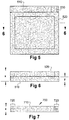
- Steps 400-440 may be modified such that the body piece and the frame piece are cut from the same matrix substrate and initially have the same specific surface area. This embodiment of the method is illustrated in FIGs 5-7 .
- a frame piece 520 is cut from a substrate blank.
- the frame piece includes the frame and lug 530.
- a body piece is initially cut as a rectangle 510 wherein the width of the rectangle is substantially equal to the width of the frame and the height of the rectangle is substantially equal to the height of the frame plus the height of the lug. It is most convenient if both pieces are cut from the same ground substance, preferably RPUF. Although the specific parameters will be determined by the particular application, with respect to the present embodiment, the thickness of each piece is taken to be 3 mm and the specific surface area of each piece is taken to be 1400 m 2 /m 3 .
- the two pieces are then juxtaposed as shown in FIG 5 with the frame piece 520 laid upon the body piece 510 so that a face of the frame piece is placed against a face of the body piece and the bottom and side edges are aligned.
- FIG 6 shows a sectional end-view of the two pieces at this point in the process, with frame piece 520 positioned on body piece 510.
- the total thickness, x, of the two pieces is 6 mm, both pieces having a thickness, y, of 3 mm.
- Pressure is then applied downwards onto frame piece 520, thereby compressing it into the edges of body piece 510. This compresses the total thickness, x, of 6mm around the edges into a total, uniform thickness, z, of about 3 mm, as shown in FIG 7 .
- the specific surface area of the body region 710 remains essentially the same, 1400 m 2 /m 3 , while the specific surface area of the frame region 720 is approximately doubled.
- the result is a matrix 700 of uniform thickness of about 3mm, z, and having a central body 710 surrounded by the frame 720.
- the body 710 retains the original thickness and specific surface area of the body piece 510, which is to say 3 mm and 1400 m 2 /m 3 , respectively.
- the specific surface area of the frame region 720 is increased to about 2800 m 2 /m 3 . Consequently, when the matrix is treated with electro-conductive material, the conductivity of the frame and lug will be greater than the conductivity of the body.
- the frame piece and body piece are permanently joined by thermal or chemical processes well known in the art.
- the resulting matrix is essentially as shown and described in FIG 1 .
- the primary objective in forming the matrix frame region is that the frame region is to have a higher specific surface area and, hence, be stiffer and stronger than the body.
- the foregoing disclosure sets forth how to produce such a frame from two separate pieces of matrix substrate cut to form the frame and body and then compressed together. It will be obvious to those skilled in the art after reading and comprehending this disclosure that this objective can be achieved in a number of ways.
- the width of the frame (F) is equal on all sides; however, the method is easily adapted to produce a frame having different widths on each side.
- the MCM includes a lug 805, which extends a distance L beyond the upper edge.
- the terms "top” 802, “bottom” 804, and “vertical sides” 801, 803 refer to the orientation of the MCM in the figures.
- This MCM can be produced from a single oversized sheet of matrix substrate 806 as shown in FIG 8b .
- oversized what is meant is that 1) the width of the sheet is equal to the width of the final MCM (W) plus the sum of the widths (F) of the opposing vertical side frames, and 2) the height of the sheet is equal to the height (H) of the final MCM plus the sum of the widths (F) of the top and bottom frames plus two times the distance (L) the lug extends beyond the top of the MCM.
- the oversized sheet is converted into the MCM by judiciously folding the edges of the sheet along the lines of the rectangle indicated as 807.
- the vertical side edges and bottom edge are folded inwards an amount equal to F, the width of the frame.
- the top edge of the sheet is folded inwards an amount equal to F plus 2L. These folds result in rectangle with double-layer edges all around.
- the lug is formed by excising excess substrate by cutting along the lines 808 indicated in FIG 8c . At this point the edges are compressed in a manner similar to that described above.
- two RPUF blanks having a specific surface area of about 1340 m 2 /m 3 are used.
- the dimensions (height x width x thickness) of the first blank are 20 cm x 30 cm x 3 mm, respectively.
- the dimensions of the second blank are 20 cm x 30 cm x 5 mm, the only difference in the dimensions of the blanks in this example is that the second blank is 2 mm thicker than the first.
- the second blank is cut by a die cutter to the shape of the frame piece 520, which includes the lug.
- the frame/lug piece is then placed on top of the first blank, and the two are compressed together to a thickness of 3.0 mm.
- the compressed sheets are then placed in an oven for two hours at 200 degrees Celsius. This causes the two sections to fuse into a single matrix having one uniform thickness and with a body specific surface area of about 1340 m 2 /m 3 and a frame specific surface area of about 2680 m 2 /m 3 .
- a MCM-based current collector is produced.
- electrical conductance of the surface of the matrix may be enhanced by cleaning, etching, and electroless plating the matrix in that order.
- a RPUF sheet is placed in a solution of 10% lead acetate in glacial acidic acid at the room temperature for about two minutes. The sheet is then removed from the solution, and any excess solution removed by washing. The sheet is then placed in a solution of 50 grams per liter of potassium dichromate in a mixture of 75% by weight water and 25% by weight of 98% sulfuric acid for about one minute. The sheet is then removed from the mixture and washed. The sheet is next immersed in a solution of three grams per liter of potassium borohydride and water for 20 minutes.
- the sheet is again washed and is either electroless plated with nickel or copper, or electroplated with copper, silver, lead, cadmium, or alloys using electroless solutions well known in the art of electroplating.
- the sheet is now ready for cutting, joining, and pasting as described above.
- a second technique for enhancing the electrical conductance of the RPUF starting material is by spraying the polyurethane surface with a metallic substance like silver, nickel, copper, or nickel graphite based conductive spray.
- Conductive coating spray is widely used in electronics industry.
- Silver based conductive sprays are well known in the field and are commercially available.
- the RPUF may be first washed with water and then dried in an oven with the temperature set to 50 degree Celsius. The RPUF surface is then sprayed with silver based conductive spray in a clean environment.
- a third technique for enhancing the electrical conductance of the RPFU matrix is by placing the RPUF in a mixture of 5% by weight P-toluene sulfonic acid and 95% by weight furfuryl alcohol for 30 seconds, removing the RPUF from the mixture, ridding it of any excess solution, air drying the infiltrated RPUF for approximately two hours to allow furfuryl to cross link and form furan plastic, and placing the RPUF in a high temperature inert gas furnace for 1 hour at 1100 degree Celsius to covert the RPUF to glassy carbon.
- a metal or metal alloy may be applied to a RPUF matrix in order to form a bonding surface for the electro-active paste. Numerous techniques are available for this step. Three are provided here.
- nickel is applied to the RPUF matrix by electroless nickel plating techniques and electroless nickel plating solutions well known in the field.
- lead or lead alloy electroplating as commonly known in the art may be used to coat the RPUF matrix.
- Appropriate lead and lead alloy electroplating solutions are well known in the field and may be obtained from numerous commercial sources.
- MIM metal injection molding
- an MIM process used to apply nickel onto the RPUF matrix includes placing the matrix in a mold, inserting the mold in a molding machine similar to those used for standard plastic injection, providing the molding machine with nickel powder combined with plastic binders, which allow the metal to be injected into a mold, operating the molding machine, and, after the part is molded, removing the binders with solvents and a thermal process.
- the nickel powder is sintered at a temperature high enough to bind the particles but not to melt the nickel.
- the sintered nickel covered the conductive surface of the RPUF matrix.
- Example 1 two 12 V batteries having capacities of 12 ampere hour (Ah) and 100 Ah were used in the comparisons. Each battery capacity was based on 12 V battery discharge at 10 hours discharge rate (C/10).
- Lead acid batteries using prototype MCM-based electrodes produced in accordance with the present invention were compared against lead acid batteries using carbon foam electrodes and conventionally made lead acid batteries. Comparison data on electrodes for the two capacities of battery are given in TABLE 1 and TABLE 2, respectively, where “Char.” stands for characteristics; “C foam,” carbon foam current collector, “Conv,” conventional current collector; “PAM,” positive active mass; “Util,” utilization; “Wh/kg,” watt hour/kg; “W/kg,” watt/kg. TABLE 1 12 Ah Battery Char.
- an MCM with a frame and lug attached to the body was fabricated as disclosed above for a 12V 100Ah lead acid battery.
- the MCM had dimensions of 185 mm x 152 mm x 2 mm (height x width x thickness).
- the RPUF was made conductive by cleaning and etching followed by electroless plating and was subsequently electroplated by lead electroplating, as described above.
- the weight of this current collector was measured at the end of each phase of fabrication. The weight was 20 gm with non-conductive RPUF substrate, 22 gm after conductive material was applied to the assembled MCM, and 85 gm total weight after the matrix was electroplated. This may be compared with a weight of approximately 115 gm for a traditional lead current collector having the same dimensions.
Priority Applications (1)
| Application Number | Priority Date | Filing Date | Title |
|---|---|---|---|
| PL10738170T PL2394319T3 (pl) | 2009-02-05 | 2010-01-05 | Matryca o wielu przewodnościach dla odbieraków prądu akumulatora |
Applications Claiming Priority (2)
| Application Number | Priority Date | Filing Date | Title |
|---|---|---|---|
| US20704809P | 2009-02-05 | 2009-02-05 | |
| PCT/CA2010/000006 WO2010088755A1 (en) | 2009-02-05 | 2010-01-05 | Multiply-conductive matrix for battery current collectors |
Publications (3)
| Publication Number | Publication Date |
|---|---|
| EP2394319A1 EP2394319A1 (en) | 2011-12-14 |
| EP2394319A4 EP2394319A4 (en) | 2016-12-21 |
| EP2394319B1 true EP2394319B1 (en) | 2020-02-19 |
Family
ID=42541617
Family Applications (1)
| Application Number | Title | Priority Date | Filing Date |
|---|---|---|---|
| EP10738170.9A Active EP2394319B1 (en) | 2009-02-05 | 2010-01-05 | Multiply-conductive matrix for battery current collectors |
Country Status (13)
| Country | Link |
|---|---|
| US (1) | US9178217B2 (ja) |
| EP (1) | EP2394319B1 (ja) |
| JP (1) | JP5595423B2 (ja) |
| KR (1) | KR101679095B1 (ja) |
| CN (1) | CN102308415B (ja) |
| AU (1) | AU2010210323B2 (ja) |
| BR (1) | BRPI1008746A2 (ja) |
| CA (1) | CA2726308C (ja) |
| MX (1) | MX2011008194A (ja) |
| PL (1) | PL2394319T3 (ja) |
| RU (1) | RU2558942C2 (ja) |
| WO (1) | WO2010088755A1 (ja) |
| ZA (1) | ZA201106413B (ja) |
Families Citing this family (18)
| Publication number | Priority date | Publication date | Assignee | Title |
|---|---|---|---|---|
| MX2011008194A (es) | 2009-02-05 | 2011-12-06 | Evt Power Inc | Matriz de conduccion multiple para colectores de corriente usados en baterias. |
| CA2817815A1 (en) * | 2010-11-10 | 2012-05-18 | Epic Ventures Inc. | Lead acid cell with active materials held in a lattice |
| CN104040764B (zh) | 2011-09-07 | 2018-02-27 | 24M技术公司 | 具有多孔集流体的半固体电极电池及其制造方法 |
| US20130171502A1 (en) * | 2011-12-29 | 2013-07-04 | Guorong Chen | Hybrid electrode and surface-mediated cell-based super-hybrid energy storage device containing same |
| US9263721B2 (en) | 2012-01-13 | 2016-02-16 | Energy Power Systems LLC | Lead-acid battery design having versatile form factor |
| US8808914B2 (en) | 2012-01-13 | 2014-08-19 | Energy Power Systems, LLC | Lead-acid battery design having versatile form factor |
| US9595360B2 (en) | 2012-01-13 | 2017-03-14 | Energy Power Systems LLC | Metallic alloys having amorphous, nano-crystalline, or microcrystalline structure |
| US9178200B2 (en) * | 2012-05-18 | 2015-11-03 | 24M Technologies, Inc. | Electrochemical cells and methods of manufacturing the same |
| US9401501B2 (en) | 2012-05-18 | 2016-07-26 | 24M Technologies, Inc. | Electrochemical cells and methods of manufacturing the same |
| EP3216067B1 (en) | 2014-11-05 | 2021-09-15 | 24m Technologies, Inc. | Electrochemical cells having semi-solid electrodes and methods of manufacturing the same |
| JP6789938B2 (ja) | 2015-06-18 | 2020-11-25 | 24エム・テクノロジーズ・インコーポレイテッド24M Technologies, Inc. | シングルパウチバッテリセル及びその製造方法 |
| DE102016220975A1 (de) * | 2016-10-25 | 2018-04-26 | Robert Bosch Gmbh | Stromkollektor für eine Energiespeicherzelle zum Speichern elektrischer Energie |
| US10665909B2 (en) | 2017-07-17 | 2020-05-26 | International Business Machines Corporation | Battery thermal run-away and combustion prevention system |
| EP3701578A2 (en) * | 2017-10-24 | 2020-09-02 | Andrzej Czerwinski | A composite lead-acid battery comprising current collectors based on shaped elements made of conductive porous carbon and processes for manufacturing |
| WO2019153277A1 (zh) * | 2018-02-09 | 2019-08-15 | 深圳前海优容科技有限公司 | 电池、电池电芯及集流体 |
| US11742525B2 (en) | 2020-02-07 | 2023-08-29 | 24M Technologies, Inc. | Divided energy electrochemical cell systems and methods of producing the same |
| US20230187652A1 (en) * | 2021-12-10 | 2023-06-15 | Uop Llc | Current collector for redox flow batteries |
| CN116905155A (zh) * | 2023-09-11 | 2023-10-20 | 远东铜箔(宜宾)有限公司 | 一种用于制备电池负极集流体的铜丝线纺织布 |
Family Cites Families (44)
| Publication number | Priority date | Publication date | Assignee | Title |
|---|---|---|---|---|
| US3635676A (en) | 1969-11-05 | 1972-01-18 | Atomic Energy Commission | Method for increasing the strength of carbon foam |
| US3709843A (en) * | 1970-04-09 | 1973-01-09 | Olin Corp | Polyurethane foams having increased density |
| US3720574A (en) | 1971-07-28 | 1973-03-13 | Scott Paper Co | Filter element |
| JPS57210569A (en) | 1981-06-19 | 1982-12-24 | Matsushita Electric Ind Co Ltd | Battery constituted by use of resin electrodes |
| US4436601A (en) | 1981-07-24 | 1984-03-13 | Diamond Shamrock Corporation | Metal removal process |
| US4535040A (en) | 1982-01-20 | 1985-08-13 | General Motors Corporation | Battery grid |
| US4444852A (en) * | 1982-08-27 | 1984-04-24 | The United States Of America As Represented By The United States Department Of Energy | Size and weight graded multi-ply laminar electrodes |
| US4606383A (en) | 1983-12-15 | 1986-08-19 | Wirtz Manufacturing Company, Inc. | Battery grid pasting machine |
| US4975515A (en) | 1987-10-21 | 1990-12-04 | Ethyl Corporation | Polyurethanes |
| JPH06509992A (ja) * | 1991-08-12 | 1994-11-10 | デュアル・リミテッド | タブ付き又は索引付きシート |
| EP0634971B1 (en) * | 1992-04-10 | 1998-05-27 | W.L. Gore & Associates, Inc. | A method of ultrasonically welding articles of porous polytetrafluoroethylene |
| FR2705834B1 (fr) * | 1993-05-26 | 1995-06-30 | Accumulateurs Fixes | Procédé de liaison d'une connexion métallique sur une électrode dont l'âme a une structure fibreuse ou de type mousse pour générateur électrochimique, et électrode obtenue. |
| US5478676A (en) | 1994-08-02 | 1995-12-26 | Rexam Graphics | Current collector having a conductive primer layer |
| US5571415A (en) * | 1994-11-02 | 1996-11-05 | Rohm And Haas Company | Method for preparing porous polymer structures |
| US6020089A (en) * | 1994-11-07 | 2000-02-01 | Sumitomo Electric Industries, Ltd. | Electrode plate for battery |
| US5817704A (en) * | 1996-03-08 | 1998-10-06 | The Procter & Gamble Company | Heterogeneous foam materials |
| US6472105B2 (en) * | 1997-11-19 | 2002-10-29 | Mitsubishi Denki Kabushiki Kaisha | Bonding agent for cells and cell using the same |
| US6238819B1 (en) * | 1998-01-23 | 2001-05-29 | Stork, N.V. | Metal foam support, electrode and method of making same |
| US6306215B1 (en) | 1998-03-10 | 2001-10-23 | Valence Technology, Inc. | Apparatus for coating current collectors |
| JPH11323406A (ja) * | 1998-03-18 | 1999-11-26 | Mitsubishi Materials Corp | 高強度スポンジ状多孔質金属板およびその製造方法 |
| US6060198A (en) * | 1998-05-29 | 2000-05-09 | Snaper; Alvin A. | Electrochemical battery structure and method |
| US6183854B1 (en) | 1999-01-22 | 2001-02-06 | West Virginia University | Method of making a reinforced carbon foam material and related product |
| JP4292436B2 (ja) * | 1999-05-26 | 2009-07-08 | 住友電気工業株式会社 | 金属多孔質体とその製造方法およびそれを用いた電池用集電体 |
| JP3466576B2 (ja) * | 2000-11-14 | 2003-11-10 | 三井鉱山株式会社 | リチウム二次電池負極用複合材料及びリチウム二次電池 |
| CA2383094A1 (en) * | 2001-04-24 | 2002-10-24 | Nitech S.A. | Electrochemical cell |
| JP4378902B2 (ja) * | 2001-08-31 | 2009-12-09 | 三菱マテリアル株式会社 | 電極板 |
| CA2499733A1 (en) * | 2001-09-26 | 2003-04-03 | Elod Gyenge | Current collector structure and methods to improve the performance of a lead-acid battery |
| JP2003203639A (ja) * | 2001-12-28 | 2003-07-18 | Sanyo Electric Co Ltd | アルカリ蓄電池およびその製造方法 |
| US6979513B2 (en) * | 2002-06-28 | 2005-12-27 | Firefly Energy Inc. | Battery including carbon foam current collectors |
| US20040002006A1 (en) * | 2002-06-28 | 2004-01-01 | Caterpillar Inc. | Battery including carbon foam current collectors |
| US7341806B2 (en) * | 2002-12-23 | 2008-03-11 | Caterpillar Inc. | Battery having carbon foam current collector |
| US6933077B2 (en) | 2002-12-27 | 2005-08-23 | Avestor Limited Partnership | Current collector for polymer electrochemical cells and electrochemical generators thereof |
| KR100560542B1 (ko) | 2003-11-20 | 2006-03-15 | 삼성에스디아이 주식회사 | 리튬 이차 전지 |
| US20060165876A1 (en) | 2004-03-26 | 2006-07-27 | Elod Gyenge | Current Collector Structure and Methods to Improve the Performance of a Lead-Acid Battery |
| US20050235472A1 (en) * | 2004-03-26 | 2005-10-27 | Joey Jung | Method of manufacture of a battery and current collector |
| RU46130U1 (ru) * | 2004-12-16 | 2005-06-10 | Закрытое акционерное общество "ЭЛЕКТРОТЯГА" | Отрицательный электрод для свинцово-кислотного аккумулятора |
| JP5260058B2 (ja) | 2004-12-31 | 2013-08-14 | カウンシル オブ サイエンティフィック アンド インダストリアル リサーチ | 鉛蓄電池用電極の製造方法、鉛蓄電池用電極及び鉛蓄電池 |
| US20060292448A1 (en) * | 2005-02-02 | 2006-12-28 | Elod Gyenge | Current Collector Structure and Methods to Improve the Performance of a Lead-Acid Battery |
| JP4213687B2 (ja) * | 2005-07-07 | 2009-01-21 | 株式会社東芝 | 非水電解質電池及び電池パック |
| US20070051636A1 (en) | 2005-09-07 | 2007-03-08 | Inco Limited | Process for producing metal foams having uniform cell structure |
| WO2008002024A1 (en) | 2006-06-26 | 2008-01-03 | Lg Chem, Ltd. | Electrode plate for battery cell and process of preparing the same |
| JP2010501455A (ja) * | 2006-08-18 | 2010-01-21 | ファイアフライ エナジー インコーポレイテッド | 複合炭素発泡体 |
| US8399134B2 (en) * | 2007-11-20 | 2013-03-19 | Firefly Energy, Inc. | Lead acid battery including a two-layer carbon foam current collector |
| MX2011008194A (es) | 2009-02-05 | 2011-12-06 | Evt Power Inc | Matriz de conduccion multiple para colectores de corriente usados en baterias. |
-
2010
- 2010-01-05 MX MX2011008194A patent/MX2011008194A/es active IP Right Grant
- 2010-01-05 CA CA2726308A patent/CA2726308C/en active Active
- 2010-01-05 BR BRPI1008746A patent/BRPI1008746A2/pt not_active IP Right Cessation
- 2010-01-05 KR KR1020117020734A patent/KR101679095B1/ko active IP Right Grant
- 2010-01-05 PL PL10738170T patent/PL2394319T3/pl unknown
- 2010-01-05 RU RU2011135464/07A patent/RU2558942C2/ru active
- 2010-01-05 US US13/147,195 patent/US9178217B2/en active Active
- 2010-01-05 CN CN201080006856.XA patent/CN102308415B/zh active Active
- 2010-01-05 WO PCT/CA2010/000006 patent/WO2010088755A1/en active Application Filing
- 2010-01-05 JP JP2011548508A patent/JP5595423B2/ja active Active
- 2010-01-05 EP EP10738170.9A patent/EP2394319B1/en active Active
- 2010-01-05 AU AU2010210323A patent/AU2010210323B2/en active Active
-
2011
- 2011-09-01 ZA ZA2011/06413A patent/ZA201106413B/en unknown
Non-Patent Citations (1)
| Title |
|---|
| None * |
Also Published As
| Publication number | Publication date |
|---|---|
| CA2726308A1 (en) | 2010-08-12 |
| PL2394319T3 (pl) | 2020-07-27 |
| CA2726308C (en) | 2011-11-01 |
| KR20110132363A (ko) | 2011-12-07 |
| US9178217B2 (en) | 2015-11-03 |
| BRPI1008746A2 (pt) | 2017-05-16 |
| RU2011135464A (ru) | 2013-03-10 |
| CN102308415B (zh) | 2016-04-20 |
| AU2010210323A1 (en) | 2011-09-01 |
| WO2010088755A1 (en) | 2010-08-12 |
| ZA201106413B (en) | 2012-05-30 |
| JP2012517077A (ja) | 2012-07-26 |
| MX2011008194A (es) | 2011-12-06 |
| RU2558942C2 (ru) | 2015-08-10 |
| EP2394319A4 (en) | 2016-12-21 |
| CN102308415A (zh) | 2012-01-04 |
| US20110287314A1 (en) | 2011-11-24 |
| AU2010210323B2 (en) | 2014-01-09 |
| EP2394319A1 (en) | 2011-12-14 |
| KR101679095B1 (ko) | 2016-12-06 |
| JP5595423B2 (ja) | 2014-09-24 |
Similar Documents
| Publication | Publication Date | Title |
|---|---|---|
| EP2394319B1 (en) | Multiply-conductive matrix for battery current collectors | |
| US5965298A (en) | Electrode plate for battery and process for producing the same | |
| US7060391B2 (en) | Current collector structure and methods to improve the performance of a lead-acid battery | |
| US9368788B2 (en) | Layered iron electrode | |
| US4237205A (en) | Pocket grid for alkaline battery plates | |
| CN102985595B (zh) | 用于电化学设备的集电流器的制作方法 | |
| JP2017517131A (ja) | 鉛酸蓄電池およびかかる蓄電池を製造するための方法 | |
| CN113745450A (zh) | 一种锂离子电池厚电极结构 | |
| US5200282A (en) | Nickel electrode and alkaline battery using the same | |
| EP0803923B1 (en) | A method for varying the density of plated foam and a battery electrode comprising a plated porous metal substrate and sintered metal powder applied thereto | |
| CN105143519B (zh) | 涂覆的铁电极及其制备方法 | |
| CN113506877A (zh) | 一种高能量密度的微孔锂电池电极及制备方法 | |
| US5229228A (en) | Current collector/support for a lead/lead oxide battery | |
| CN111193030B (zh) | 一种三维多孔铝带及制备方法和正极 | |
| CN220400626U (zh) | 一种连续涂布、辊压成型的钠离子电池极片结构 | |
| EP0403052B1 (en) | Nickel electrode and alkaline battery using the same | |
| CN113036150B (zh) | 集流体、电池极片及集流体制作方法 | |
| EP2644722B1 (en) | Method for producing highly corrosion-resistant porous metal body | |
| JPS61263047A (ja) | アルカリ電池用ニツケル極 | |
| CN116646462A (zh) | 二次电池极片、二次电池及其制备方法 |
Legal Events
| Date | Code | Title | Description |
|---|---|---|---|
| PUAI | Public reference made under article 153(3) epc to a published international application that has entered the european phase |
Free format text: ORIGINAL CODE: 0009012 |
|
| 17P | Request for examination filed |
Effective date: 20110902 |
|
| AK | Designated contracting states |
Kind code of ref document: A1 Designated state(s): AT BE BG CH CY CZ DE DK EE ES FI FR GB GR HR HU IE IS IT LI LT LU LV MC MK MT NL NO PL PT RO SE SI SK SM TR |
|
| DAX | Request for extension of the european patent (deleted) | ||
| RA4 | Supplementary search report drawn up and despatched (corrected) |
Effective date: 20161117 |
|
| RIC1 | Information provided on ipc code assigned before grant |
Ipc: H01M 4/66 20060101ALI20161111BHEP Ipc: H01M 4/64 20060101ALI20161111BHEP Ipc: H01M 4/82 20060101ALI20161111BHEP Ipc: H01M 2/20 20060101AFI20161111BHEP Ipc: H01M 4/80 20060101ALI20161111BHEP |
|
| STAA | Information on the status of an ep patent application or granted ep patent |
Free format text: STATUS: EXAMINATION IS IN PROGRESS |
|
| 17Q | First examination report despatched |
Effective date: 20170906 |
|
| GRAP | Despatch of communication of intention to grant a patent |
Free format text: ORIGINAL CODE: EPIDOSNIGR1 |
|
| STAA | Information on the status of an ep patent application or granted ep patent |
Free format text: STATUS: GRANT OF PATENT IS INTENDED |
|
| INTG | Intention to grant announced |
Effective date: 20190903 |
|
| GRAS | Grant fee paid |
Free format text: ORIGINAL CODE: EPIDOSNIGR3 |
|
| GRAA | (expected) grant |
Free format text: ORIGINAL CODE: 0009210 |
|
| STAA | Information on the status of an ep patent application or granted ep patent |
Free format text: STATUS: THE PATENT HAS BEEN GRANTED |
|
| AK | Designated contracting states |
Kind code of ref document: B1 Designated state(s): AT BE BG CH CY CZ DE DK EE ES FI FR GB GR HR HU IE IS IT LI LT LU LV MC MK MT NL NO PL PT RO SE SI SK SM TR |
|
| REG | Reference to a national code |
Ref country code: GB Ref legal event code: FG4D |
|
| REG | Reference to a national code |
Ref country code: CH Ref legal event code: EP |
|
| REG | Reference to a national code |
Ref country code: DE Ref legal event code: R096 Ref document number: 602010063155 Country of ref document: DE |
|
| REG | Reference to a national code |
Ref country code: AT Ref legal event code: REF Ref document number: 1235968 Country of ref document: AT Kind code of ref document: T Effective date: 20200315 |
|
| REG | Reference to a national code |
Ref country code: IE Ref legal event code: FG4D |
|
| REG | Reference to a national code |
Ref country code: NL Ref legal event code: MP Effective date: 20200219 |
|
| PG25 | Lapsed in a contracting state [announced via postgrant information from national office to epo] |
Ref country code: NO Free format text: LAPSE BECAUSE OF FAILURE TO SUBMIT A TRANSLATION OF THE DESCRIPTION OR TO PAY THE FEE WITHIN THE PRESCRIBED TIME-LIMIT Effective date: 20200519 Ref country code: FI Free format text: LAPSE BECAUSE OF FAILURE TO SUBMIT A TRANSLATION OF THE DESCRIPTION OR TO PAY THE FEE WITHIN THE PRESCRIBED TIME-LIMIT Effective date: 20200219 |
|
| REG | Reference to a national code |
Ref country code: LT Ref legal event code: MG4D |
|
| PG25 | Lapsed in a contracting state [announced via postgrant information from national office to epo] |
Ref country code: HR Free format text: LAPSE BECAUSE OF FAILURE TO SUBMIT A TRANSLATION OF THE DESCRIPTION OR TO PAY THE FEE WITHIN THE PRESCRIBED TIME-LIMIT Effective date: 20200219 Ref country code: SE Free format text: LAPSE BECAUSE OF FAILURE TO SUBMIT A TRANSLATION OF THE DESCRIPTION OR TO PAY THE FEE WITHIN THE PRESCRIBED TIME-LIMIT Effective date: 20200219 Ref country code: LV Free format text: LAPSE BECAUSE OF FAILURE TO SUBMIT A TRANSLATION OF THE DESCRIPTION OR TO PAY THE FEE WITHIN THE PRESCRIBED TIME-LIMIT Effective date: 20200219 Ref country code: GR Free format text: LAPSE BECAUSE OF FAILURE TO SUBMIT A TRANSLATION OF THE DESCRIPTION OR TO PAY THE FEE WITHIN THE PRESCRIBED TIME-LIMIT Effective date: 20200520 Ref country code: IS Free format text: LAPSE BECAUSE OF FAILURE TO SUBMIT A TRANSLATION OF THE DESCRIPTION OR TO PAY THE FEE WITHIN THE PRESCRIBED TIME-LIMIT Effective date: 20200619 |
|
| PG25 | Lapsed in a contracting state [announced via postgrant information from national office to epo] |
Ref country code: NL Free format text: LAPSE BECAUSE OF FAILURE TO SUBMIT A TRANSLATION OF THE DESCRIPTION OR TO PAY THE FEE WITHIN THE PRESCRIBED TIME-LIMIT Effective date: 20200219 |
|
| PG25 | Lapsed in a contracting state [announced via postgrant information from national office to epo] |
Ref country code: CZ Free format text: LAPSE BECAUSE OF FAILURE TO SUBMIT A TRANSLATION OF THE DESCRIPTION OR TO PAY THE FEE WITHIN THE PRESCRIBED TIME-LIMIT Effective date: 20200219 Ref country code: LT Free format text: LAPSE BECAUSE OF FAILURE TO SUBMIT A TRANSLATION OF THE DESCRIPTION OR TO PAY THE FEE WITHIN THE PRESCRIBED TIME-LIMIT Effective date: 20200219 Ref country code: RO Free format text: LAPSE BECAUSE OF FAILURE TO SUBMIT A TRANSLATION OF THE DESCRIPTION OR TO PAY THE FEE WITHIN THE PRESCRIBED TIME-LIMIT Effective date: 20200219 Ref country code: EE Free format text: LAPSE BECAUSE OF FAILURE TO SUBMIT A TRANSLATION OF THE DESCRIPTION OR TO PAY THE FEE WITHIN THE PRESCRIBED TIME-LIMIT Effective date: 20200219 Ref country code: SM Free format text: LAPSE BECAUSE OF FAILURE TO SUBMIT A TRANSLATION OF THE DESCRIPTION OR TO PAY THE FEE WITHIN THE PRESCRIBED TIME-LIMIT Effective date: 20200219 Ref country code: SK Free format text: LAPSE BECAUSE OF FAILURE TO SUBMIT A TRANSLATION OF THE DESCRIPTION OR TO PAY THE FEE WITHIN THE PRESCRIBED TIME-LIMIT Effective date: 20200219 Ref country code: PT Free format text: LAPSE BECAUSE OF FAILURE TO SUBMIT A TRANSLATION OF THE DESCRIPTION OR TO PAY THE FEE WITHIN THE PRESCRIBED TIME-LIMIT Effective date: 20200712 Ref country code: DK Free format text: LAPSE BECAUSE OF FAILURE TO SUBMIT A TRANSLATION OF THE DESCRIPTION OR TO PAY THE FEE WITHIN THE PRESCRIBED TIME-LIMIT Effective date: 20200219 Ref country code: ES Free format text: LAPSE BECAUSE OF FAILURE TO SUBMIT A TRANSLATION OF THE DESCRIPTION OR TO PAY THE FEE WITHIN THE PRESCRIBED TIME-LIMIT Effective date: 20200219 |
|
| REG | Reference to a national code |
Ref country code: AT Ref legal event code: MK05 Ref document number: 1235968 Country of ref document: AT Kind code of ref document: T Effective date: 20200219 |
|
| REG | Reference to a national code |
Ref country code: DE Ref legal event code: R097 Ref document number: 602010063155 Country of ref document: DE |
|
| REG | Reference to a national code |
Ref country code: DE Ref legal event code: R079 Ref document number: 602010063155 Country of ref document: DE Free format text: PREVIOUS MAIN CLASS: H01M0002200000 Ipc: H01M0050500000 |
|
| PLBE | No opposition filed within time limit |
Free format text: ORIGINAL CODE: 0009261 |
|
| STAA | Information on the status of an ep patent application or granted ep patent |
Free format text: STATUS: NO OPPOSITION FILED WITHIN TIME LIMIT |
|
| 26N | No opposition filed |
Effective date: 20201120 |
|
| PG25 | Lapsed in a contracting state [announced via postgrant information from national office to epo] |
Ref country code: AT Free format text: LAPSE BECAUSE OF FAILURE TO SUBMIT A TRANSLATION OF THE DESCRIPTION OR TO PAY THE FEE WITHIN THE PRESCRIBED TIME-LIMIT Effective date: 20200219 Ref country code: IT Free format text: LAPSE BECAUSE OF FAILURE TO SUBMIT A TRANSLATION OF THE DESCRIPTION OR TO PAY THE FEE WITHIN THE PRESCRIBED TIME-LIMIT Effective date: 20200219 |
|
| PG25 | Lapsed in a contracting state [announced via postgrant information from national office to epo] |
Ref country code: SI Free format text: LAPSE BECAUSE OF FAILURE TO SUBMIT A TRANSLATION OF THE DESCRIPTION OR TO PAY THE FEE WITHIN THE PRESCRIBED TIME-LIMIT Effective date: 20200219 |
|
| PG25 | Lapsed in a contracting state [announced via postgrant information from national office to epo] |
Ref country code: MC Free format text: LAPSE BECAUSE OF FAILURE TO SUBMIT A TRANSLATION OF THE DESCRIPTION OR TO PAY THE FEE WITHIN THE PRESCRIBED TIME-LIMIT Effective date: 20200219 |
|
| REG | Reference to a national code |
Ref country code: CH Ref legal event code: PL |
|
| PG25 | Lapsed in a contracting state [announced via postgrant information from national office to epo] |
Ref country code: LU Free format text: LAPSE BECAUSE OF NON-PAYMENT OF DUE FEES Effective date: 20210105 |
|
| REG | Reference to a national code |
Ref country code: BE Ref legal event code: MM Effective date: 20210131 |
|
| PG25 | Lapsed in a contracting state [announced via postgrant information from national office to epo] |
Ref country code: LI Free format text: LAPSE BECAUSE OF NON-PAYMENT OF DUE FEES Effective date: 20210131 Ref country code: CH Free format text: LAPSE BECAUSE OF NON-PAYMENT OF DUE FEES Effective date: 20210131 |
|
| PG25 | Lapsed in a contracting state [announced via postgrant information from national office to epo] |
Ref country code: IE Free format text: LAPSE BECAUSE OF NON-PAYMENT OF DUE FEES Effective date: 20210105 |
|
| PG25 | Lapsed in a contracting state [announced via postgrant information from national office to epo] |
Ref country code: BE Free format text: LAPSE BECAUSE OF NON-PAYMENT OF DUE FEES Effective date: 20210131 |
|
| PGFP | Annual fee paid to national office [announced via postgrant information from national office to epo] |
Ref country code: BG Payment date: 20221229 Year of fee payment: 14 |
|
| PGFP | Annual fee paid to national office [announced via postgrant information from national office to epo] |
Ref country code: PL Payment date: 20221229 Year of fee payment: 14 |
|
| PGFP | Annual fee paid to national office [announced via postgrant information from national office to epo] |
Ref country code: FR Payment date: 20230110 Year of fee payment: 14 |
|
| PG25 | Lapsed in a contracting state [announced via postgrant information from national office to epo] |
Ref country code: HU Free format text: LAPSE BECAUSE OF FAILURE TO SUBMIT A TRANSLATION OF THE DESCRIPTION OR TO PAY THE FEE WITHIN THE PRESCRIBED TIME-LIMIT; INVALID AB INITIO Effective date: 20100105 Ref country code: CY Free format text: LAPSE BECAUSE OF FAILURE TO SUBMIT A TRANSLATION OF THE DESCRIPTION OR TO PAY THE FEE WITHIN THE PRESCRIBED TIME-LIMIT Effective date: 20200219 |
|
| PGFP | Annual fee paid to national office [announced via postgrant information from national office to epo] |
Ref country code: GB Payment date: 20231116 Year of fee payment: 15 |
|
| PG25 | Lapsed in a contracting state [announced via postgrant information from national office to epo] |
Ref country code: MK Free format text: LAPSE BECAUSE OF FAILURE TO SUBMIT A TRANSLATION OF THE DESCRIPTION OR TO PAY THE FEE WITHIN THE PRESCRIBED TIME-LIMIT Effective date: 20200219 |
|
| PGFP | Annual fee paid to national office [announced via postgrant information from national office to epo] |
Ref country code: DE Payment date: 20231107 Year of fee payment: 15 |