EP2393456B1 - Mélangeur et procédé pour mélanger des composés diphasiques - Google Patents
Mélangeur et procédé pour mélanger des composés diphasiques Download PDFInfo
- Publication number
- EP2393456B1 EP2393456B1 EP20090785803 EP09785803A EP2393456B1 EP 2393456 B1 EP2393456 B1 EP 2393456B1 EP 20090785803 EP20090785803 EP 20090785803 EP 09785803 A EP09785803 A EP 09785803A EP 2393456 B1 EP2393456 B1 EP 2393456B1
- Authority
- EP
- European Patent Office
- Prior art keywords
- chamber
- mixing
- dispensing
- mixing unit
- unit
- Prior art date
- Legal status (The legal status is an assumption and is not a legal conclusion. Google has not performed a legal analysis and makes no representation as to the accuracy of the status listed.)
- Active
Links
- 238000002156 mixing Methods 0.000 title claims description 71
- 150000001875 compounds Chemical class 0.000 title claims description 51
- 238000000034 method Methods 0.000 title claims description 19
- 230000002051 biphasic effect Effects 0.000 title claims description 11
- 239000007791 liquid phase Substances 0.000 claims description 18
- 239000007790 solid phase Substances 0.000 claims description 12
- 238000003756 stirring Methods 0.000 claims description 8
- 230000008878 coupling Effects 0.000 claims description 4
- 238000010168 coupling process Methods 0.000 claims description 4
- 238000005859 coupling reaction Methods 0.000 claims description 4
- 238000001125 extrusion Methods 0.000 claims description 3
- 239000013013 elastic material Substances 0.000 claims 1
- 239000007788 liquid Substances 0.000 description 8
- 238000005086 pumping Methods 0.000 description 7
- 239000012071 phase Substances 0.000 description 6
- 238000011882 arthroplasty Methods 0.000 description 5
- 239000000463 material Substances 0.000 description 3
- 230000005855 radiation Effects 0.000 description 3
- 206010073306 Exposure to radiation Diseases 0.000 description 2
- 239000012530 fluid Substances 0.000 description 2
- 230000036512 infertility Effects 0.000 description 2
- 210000000988 bone and bone Anatomy 0.000 description 1
- 238000010276 construction Methods 0.000 description 1
- 230000000694 effects Effects 0.000 description 1
- 238000011049 filling Methods 0.000 description 1
- 239000012634 fragment Substances 0.000 description 1
- 239000011521 glass Substances 0.000 description 1
- 230000002452 interceptive effect Effects 0.000 description 1
- 239000000203 mixture Substances 0.000 description 1
- 238000011017 operating method Methods 0.000 description 1
- 238000002360 preparation method Methods 0.000 description 1
- 238000007789 sealing Methods 0.000 description 1
- 238000001356 surgical procedure Methods 0.000 description 1
Images


Classifications
-
- B—PERFORMING OPERATIONS; TRANSPORTING
- B01—PHYSICAL OR CHEMICAL PROCESSES OR APPARATUS IN GENERAL
- B01F—MIXING, e.g. DISSOLVING, EMULSIFYING OR DISPERSING
- B01F21/00—Dissolving
- B01F21/02—Methods
-
- B—PERFORMING OPERATIONS; TRANSPORTING
- B01—PHYSICAL OR CHEMICAL PROCESSES OR APPARATUS IN GENERAL
- B01F—MIXING, e.g. DISSOLVING, EMULSIFYING OR DISPERSING
- B01F31/00—Mixers with shaking, oscillating, or vibrating mechanisms
- B01F31/40—Mixers with shaking, oscillating, or vibrating mechanisms with an axially oscillating rotary stirrer
-
- B—PERFORMING OPERATIONS; TRANSPORTING
- B01—PHYSICAL OR CHEMICAL PROCESSES OR APPARATUS IN GENERAL
- B01F—MIXING, e.g. DISSOLVING, EMULSIFYING OR DISPERSING
- B01F23/00—Mixing according to the phases to be mixed, e.g. dispersing or emulsifying
- B01F23/50—Mixing liquids with solids
- B01F23/51—Methods thereof
-
- B—PERFORMING OPERATIONS; TRANSPORTING
- B01—PHYSICAL OR CHEMICAL PROCESSES OR APPARATUS IN GENERAL
- B01F—MIXING, e.g. DISSOLVING, EMULSIFYING OR DISPERSING
- B01F27/00—Mixers with rotary stirring devices in fixed receptacles; Kneaders
- B01F27/05—Stirrers
- B01F27/11—Stirrers characterised by the configuration of the stirrers
- B01F27/113—Propeller-shaped stirrers for producing an axial flow, e.g. shaped like a ship or aircraft propeller
-
- B—PERFORMING OPERATIONS; TRANSPORTING
- B01—PHYSICAL OR CHEMICAL PROCESSES OR APPARATUS IN GENERAL
- B01F—MIXING, e.g. DISSOLVING, EMULSIFYING OR DISPERSING
- B01F33/00—Other mixers; Mixing plants; Combinations of mixers
- B01F33/50—Movable or transportable mixing devices or plants
- B01F33/501—Movable mixing devices, i.e. readily shifted or displaced from one place to another, e.g. portable during use
- B01F33/5011—Movable mixing devices, i.e. readily shifted or displaced from one place to another, e.g. portable during use portable during use, e.g. hand-held
- B01F33/50112—Movable mixing devices, i.e. readily shifted or displaced from one place to another, e.g. portable during use portable during use, e.g. hand-held of the syringe or cartridge type
-
- B—PERFORMING OPERATIONS; TRANSPORTING
- B01—PHYSICAL OR CHEMICAL PROCESSES OR APPARATUS IN GENERAL
- B01F—MIXING, e.g. DISSOLVING, EMULSIFYING OR DISPERSING
- B01F35/00—Accessories for mixers; Auxiliary operations or auxiliary devices; Parts or details of general application
- B01F35/30—Driving arrangements; Transmissions; Couplings; Brakes
- B01F35/32—Driving arrangements
- B01F35/325—Driving reciprocating or oscillating stirrers
-
- B—PERFORMING OPERATIONS; TRANSPORTING
- B01—PHYSICAL OR CHEMICAL PROCESSES OR APPARATUS IN GENERAL
- B01F—MIXING, e.g. DISSOLVING, EMULSIFYING OR DISPERSING
- B01F35/00—Accessories for mixers; Auxiliary operations or auxiliary devices; Parts or details of general application
- B01F35/71—Feed mechanisms
- B01F35/713—Feed mechanisms comprising breaking packages or parts thereof, e.g. piercing or opening sealing elements between compartments or cartridges
- B01F35/7131—Breaking or perforating packages, containers or vials
-
- B—PERFORMING OPERATIONS; TRANSPORTING
- B01—PHYSICAL OR CHEMICAL PROCESSES OR APPARATUS IN GENERAL
- B01F—MIXING, e.g. DISSOLVING, EMULSIFYING OR DISPERSING
- B01F35/00—Accessories for mixers; Auxiliary operations or auxiliary devices; Parts or details of general application
- B01F35/71—Feed mechanisms
- B01F35/716—Feed mechanisms characterised by the relative arrangement of the containers for feeding or mixing the components
- B01F35/7163—Feed mechanisms characterised by the relative arrangement of the containers for feeding or mixing the components the containers being connected in a mouth-to-mouth, end-to-end disposition, i.e. the openings are juxtaposed before contacting the contents
-
- B—PERFORMING OPERATIONS; TRANSPORTING
- B01—PHYSICAL OR CHEMICAL PROCESSES OR APPARATUS IN GENERAL
- B01F—MIXING, e.g. DISSOLVING, EMULSIFYING OR DISPERSING
- B01F35/00—Accessories for mixers; Auxiliary operations or auxiliary devices; Parts or details of general application
- B01F35/71—Feed mechanisms
- B01F35/717—Feed mechanisms characterised by the means for feeding the components to the mixer
- B01F35/7174—Feed mechanisms characterised by the means for feeding the components to the mixer using pistons, plungers or syringes
-
- B—PERFORMING OPERATIONS; TRANSPORTING
- B01—PHYSICAL OR CHEMICAL PROCESSES OR APPARATUS IN GENERAL
- B01F—MIXING, e.g. DISSOLVING, EMULSIFYING OR DISPERSING
- B01F35/00—Accessories for mixers; Auxiliary operations or auxiliary devices; Parts or details of general application
- B01F35/75—Discharge mechanisms
- B01F35/752—Discharge mechanisms with arrangements for converting the mechanism from mixing to discharging, e.g. by either guiding a mixture back into a receptacle or discharging it
-
- B—PERFORMING OPERATIONS; TRANSPORTING
- B01—PHYSICAL OR CHEMICAL PROCESSES OR APPARATUS IN GENERAL
- B01F—MIXING, e.g. DISSOLVING, EMULSIFYING OR DISPERSING
- B01F35/00—Accessories for mixers; Auxiliary operations or auxiliary devices; Parts or details of general application
- B01F35/75—Discharge mechanisms
- B01F35/754—Discharge mechanisms characterised by the means for discharging the components from the mixer
- B01F35/75425—Discharge mechanisms characterised by the means for discharging the components from the mixer using pistons or plungers
-
- B—PERFORMING OPERATIONS; TRANSPORTING
- B01—PHYSICAL OR CHEMICAL PROCESSES OR APPARATUS IN GENERAL
- B01F—MIXING, e.g. DISSOLVING, EMULSIFYING OR DISPERSING
- B01F35/00—Accessories for mixers; Auxiliary operations or auxiliary devices; Parts or details of general application
- B01F35/75—Discharge mechanisms
- B01F35/754—Discharge mechanisms characterised by the means for discharging the components from the mixer
- B01F35/75455—Discharge mechanisms characterised by the means for discharging the components from the mixer using a rotary discharge means, e.g. a screw beneath the receptacle
- B01F35/754551—Discharge mechanisms characterised by the means for discharging the components from the mixer using a rotary discharge means, e.g. a screw beneath the receptacle using helical screws
-
- A—HUMAN NECESSITIES
- A61—MEDICAL OR VETERINARY SCIENCE; HYGIENE
- A61B—DIAGNOSIS; SURGERY; IDENTIFICATION
- A61B17/00—Surgical instruments, devices or methods, e.g. tourniquets
- A61B17/56—Surgical instruments or methods for treatment of bones or joints; Devices specially adapted therefor
- A61B17/58—Surgical instruments or methods for treatment of bones or joints; Devices specially adapted therefor for osteosynthesis, e.g. bone plates, screws, setting implements or the like
- A61B17/88—Osteosynthesis instruments; Methods or means for implanting or extracting internal or external fixation devices
- A61B17/8802—Equipment for handling bone cement or other fluid fillers
- A61B17/8833—Osteosynthesis tools specially adapted for handling bone cement or fluid fillers; Means for supplying bone cement or fluid fillers to introducing tools, e.g. cartridge handling means
- A61B2017/8838—Osteosynthesis tools specially adapted for handling bone cement or fluid fillers; Means for supplying bone cement or fluid fillers to introducing tools, e.g. cartridge handling means for mixing bone cement or fluid fillers
-
- A—HUMAN NECESSITIES
- A61—MEDICAL OR VETERINARY SCIENCE; HYGIENE
- A61F—FILTERS IMPLANTABLE INTO BLOOD VESSELS; PROSTHESES; DEVICES PROVIDING PATENCY TO, OR PREVENTING COLLAPSING OF, TUBULAR STRUCTURES OF THE BODY, e.g. STENTS; ORTHOPAEDIC, NURSING OR CONTRACEPTIVE DEVICES; FOMENTATION; TREATMENT OR PROTECTION OF EYES OR EARS; BANDAGES, DRESSINGS OR ABSORBENT PADS; FIRST-AID KITS
- A61F2/00—Filters implantable into blood vessels; Prostheses, i.e. artificial substitutes or replacements for parts of the body; Appliances for connecting them with the body; Devices providing patency to, or preventing collapsing of, tubular structures of the body, e.g. stents
- A61F2/02—Prostheses implantable into the body
- A61F2/30—Joints
- A61F2/46—Special tools or methods for implanting or extracting artificial joints, accessories, bone grafts or substitutes, or particular adaptations therefor
- A61F2002/4688—Special tools or methods for implanting or extracting artificial joints, accessories, bone grafts or substitutes, or particular adaptations therefor having operating or control means
- A61F2002/469—Special tools or methods for implanting or extracting artificial joints, accessories, bone grafts or substitutes, or particular adaptations therefor having operating or control means electrical
-
- A—HUMAN NECESSITIES
- A61—MEDICAL OR VETERINARY SCIENCE; HYGIENE
- A61F—FILTERS IMPLANTABLE INTO BLOOD VESSELS; PROSTHESES; DEVICES PROVIDING PATENCY TO, OR PREVENTING COLLAPSING OF, TUBULAR STRUCTURES OF THE BODY, e.g. STENTS; ORTHOPAEDIC, NURSING OR CONTRACEPTIVE DEVICES; FOMENTATION; TREATMENT OR PROTECTION OF EYES OR EARS; BANDAGES, DRESSINGS OR ABSORBENT PADS; FIRST-AID KITS
- A61F2/00—Filters implantable into blood vessels; Prostheses, i.e. artificial substitutes or replacements for parts of the body; Appliances for connecting them with the body; Devices providing patency to, or preventing collapsing of, tubular structures of the body, e.g. stents
- A61F2/02—Prostheses implantable into the body
- A61F2/30—Joints
- A61F2/46—Special tools or methods for implanting or extracting artificial joints, accessories, bone grafts or substitutes, or particular adaptations therefor
- A61F2002/4688—Special tools or methods for implanting or extracting artificial joints, accessories, bone grafts or substitutes, or particular adaptations therefor having operating or control means
- A61F2002/4692—Special tools or methods for implanting or extracting artificial joints, accessories, bone grafts or substitutes, or particular adaptations therefor having operating or control means fluid
- A61F2002/4693—Special tools or methods for implanting or extracting artificial joints, accessories, bone grafts or substitutes, or particular adaptations therefor having operating or control means fluid hydraulic
-
- B—PERFORMING OPERATIONS; TRANSPORTING
- B01—PHYSICAL OR CHEMICAL PROCESSES OR APPARATUS IN GENERAL
- B01F—MIXING, e.g. DISSOLVING, EMULSIFYING OR DISPERSING
- B01F27/00—Mixers with rotary stirring devices in fixed receptacles; Kneaders
- B01F27/05—Stirrers
- B01F27/11—Stirrers characterised by the configuration of the stirrers
- B01F27/112—Stirrers characterised by the configuration of the stirrers with arms, paddles, vanes or blades
- B01F27/1125—Stirrers characterised by the configuration of the stirrers with arms, paddles, vanes or blades with vanes or blades extending parallel or oblique to the stirrer axis
-
- B—PERFORMING OPERATIONS; TRANSPORTING
- B01—PHYSICAL OR CHEMICAL PROCESSES OR APPARATUS IN GENERAL
- B01F—MIXING, e.g. DISSOLVING, EMULSIFYING OR DISPERSING
- B01F35/00—Accessories for mixers; Auxiliary operations or auxiliary devices; Parts or details of general application
- B01F35/30—Driving arrangements; Transmissions; Couplings; Brakes
- B01F35/32—Driving arrangements
- B01F35/32005—Type of drive
- B01F35/3202—Hand driven
Definitions
- the invention relates to the mixing of biphasic compounds, particularly biphasic compounds used in the arthroplasty field for reconstructing or filling bone structures.
- mixers which mix a liquid phase with a solid phase in order to make the biphasic compound to dispense.
- the known types of mixers can provide, for this purpose, a phial with the liquid phase connectable to a syringe containing the solid phase.
- the liquid contained in the phial is put into the syringe inside which a stirring device mixes the compound.
- the phial is positioned inside a container and to get the liquid out without any direct manual contact, devices are used that can be manoeuvred from outside and designed to break the phial.
- the liquid that comes out of the phial must then be put inside the syringe by means of suitable pouring means that transfer the liquid from the phial container to the mixing syringe.
- Another aspect of the known types of mixer concern the next phases of compound preparation during which, once the liquid and solid phases have come together in the syringe, the compound must be mixed by means of suitable stirring devices until a compound is obtained which is then dispensed, acting on the syringe piston.
- the known types of mixer have some drawbacks linked to the construction difficulty in fitting the syringe with effective stirring means to stir the compound and that has an accurate and controlled dispensing of the finished compound.
- a dispenser of the type known is described as an example in the application VI2002A000140 in the name of the-same applicant.
- the European application n. EP1031333 discloses a mixing device comprising a mixing space, a vacuum-generating device to generate vacuum in the mixing space and a sealed container provided in an outer container. Opening means are provided in order to break the sealed container.
- the outer container can be altered in its position with relative to the mixing member and open in this way the sealed container.
- US 2005/281132 discloses a transfer bag containing a phial. When the phial is broken, a syringe is connected to the transfer bag in order to extract the liquid of the phial and to transfer it to a container containing a solid phase.
- Document n. DE 19532015 discloses a device for mixing and dispensing multi-component products which are located in a chamber from which they can be dispensed by a piston.
- a mixing element is provided which is movable in the chamber and can be moved by the piston-actuating handle.
- the technical aim of this invention is, therefore, to provide a mixing method that allows the mixing of the liquid and solid phases, easily and in a sterile environment.
- a first advantage of the invention is that the operations of bringing the two phases together and the mixing and dispensing of the compound are obtained with a device that is relatively simple and easy to use.
- a second advantage is that all the operations are done avoiding the direct contact with the outside environment.
- Yet another advantage is that the mixer used according to the invention allows the times to be reduced needed for mixing and dispensing the compound.
- Another advantage is that the mixer used according to the invention allows dispensing of the exact doses of the compound in a controlled and accurate manner.
- the mixer used according to the invention allows the compound to be dispensed according to operating methods that minimise all possible radiation exposure risks of the operators who are performing the arthroplasty surgery operation.
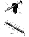
- 1 designates a mixer for biphasic compounds used according to the invention in one of its embodiments.
- the mixer 1 of biphasic compounds used according to the invention comprises one mixing unit, indicated with 3, one dispensing unit, indicated with 2 and one cartridge, indicated with 4, containing the liquid phase and which can be connected together in order to mix the liquid phase with the solid phase and to dispense a quantity of the mixed biphasic compound.
- the mixer 1 comprising a chamber 21 for containing a solid phase 22, and a cartridge 4 containing a phial 18 of a liquid phase.
- the chamber 21 and the cartridge 4 can communicate through the relative channels 19, 20 and can be joined in a removable manner, e.g. using screw means composed of an external thread 17 made by the channel 19 of the cartridge 4 and which engages with an internal thread 16 of a locking ring nut 15 turning around the channel 20 of the mixing chamber 21.
- the cartridge 4 advantageously comprises an external casing 25 made in a deformable material so that the phial 18, being the breakable type, once connected to the chamber 21, can be broken from the outside, e.g. on a breaking point 28, according to the method of the type known.
- the deformable casing can then be squeezed and the liquid transferred inside the chamber 21 through the channels 19 and 20, preferably interposing a filter - not shown in the figures - to prevent any fragments of glass from accidentally getting inside the chamber 21.
- the liquid phase is joined with the solid phase inside the chamber 21 simply, in a completely sterile fashion and with no contact with the outside and without the minimum mechanical or structural complication.
- the casing 25 is made in a flexible material - that is, that acts substantially in an elastic way - and has an internal volume 29 greater than the volume taken up by said phial 18.
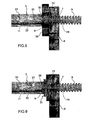
- the mixing unit 3 and the dispensing unit 2 used according to the invention are described in more detail.
- the unit 3 is in the shape of a syringe body comprising a container 24 defining inside it the mixing chamber 21, and which has on one end the channel 20 already described that has a ring nut 15 for fixing to the cartridge 4.
- the container 24 has a piston 23 which seals the chamber 21 and fixing means 10 for fixing to the dispensing unit 2 which, in the form of embodiment illustrated, are composed of an external screw 10 which engages frontally with an internal screw 9 made in one block 26 integral with the handgrip 8 of the unit 2 which is described in more detail further on.
- stirring means are arranged inside the chamber 21 which, in the form of embodiment described, comprise a stirrer 12 in the shape of a propeller driven by a longitudinal rod 11 that extends at least along the whole chamber 21, going through a hole 30 of the piston 23 and which is hermetically sealed.
- the rod 11 also comprises a gripping knob 13 which extends beyond the chamber 21 and which facilitates the propeller 12 manoeuvring.
- knob is advantageous but is not essential, for example when one wishes to use a connection between the mixing unit 3 and the dispensing unit 2 of the lateral snap-in type, e.g. composed of a prismatic coupling (e.g. dovetail) achieved by the transversal movement with respect to a longitudinal axis of the mixer (e.g. the axis of the screw 6 and/or of the chamber 21).
- a prismatic coupling e.g. dovetail
- a lateral snap-in connection 31 is schematised in figure 6 .
- the stirrer 12 When using, the stirrer 12 can be turned and moved longitudinally by means of the rod 11 which slides through the piston 23 until completing the mixing of the solid phase which is inside the chamber 21 with the liquid phase already in the cartridge 4 and until a biphasic compound is obtained, ready for final dispensing.
- the dispensing phase is carried out by means of a dispensing unit 2 that comprises an extrusion screw with an external thread 6 that engages with a corresponding internal thread 7 created inside the handgrip 8 so as to advance, subsequent to the rotation of the screw, e.g. by using the knob 5. Subsequent to rotation, the screw 6 moves forward and presses on the piston 23 forcing it to slide along the mixing chamber 21.
- a dispensing unit 2 that comprises an extrusion screw with an external thread 6 that engages with a corresponding internal thread 7 created inside the handgrip 8 so as to advance, subsequent to the rotation of the screw, e.g. by using the knob 5. Subsequent to rotation, the screw 6 moves forward and presses on the piston 23 forcing it to slide along the mixing chamber 21.
- the screw 6 has a longitudinal inner cavity 14 that houses the rod 11 in a sliding manner, so that as the screw and piston advance the rod 11 returns and is concealed inside the cavity 14 without interfering with the dispensing action made by the unit 2.
- the mixing unit 3 comprises a container 24, substantially in the shape of a syringe, defining the mixing chamber 21 and communicating, on one of its ends, with the channel 20.
- the screw means, described previously, are also on this same end for the removable connection to the cartridge 4.
- the container 24 is associated with a piston 23 which closes (thus sealing) the mixing chamber 21 to which a manually operated stem 32 is integrally connected, used to dispense the compound, as is more clearly explained below.
- the stem 32 has, on its free end, an eyelet 33 for manual thrusting, or alternatively for being connected to thrusting means which are not represented in the figures enclosed: the thrust exerted on the eyelet 33 does, of course, allow the compound to be dispensed through the channel 20.
- the stem 32 is hollow inside and its axial cavity communicates with the hole 30 of the piston 23. In the axial cavity of the stem 32 the rod 11 is engaged in a sliding manner and has the stirrer 12 for mixing the compound on its end.
- the stem 32 also has a pair of opposing longitudinal slots 34 that communicate with its axial cavity and along which a sort of handgrip 35 is guided in a sliding manner: the latter comes out from said slots 34 sideways and allows the rod 11 to move inside the chamber 21 to mix the compound.
- the stirrer 12 represented in particular in figure 8 , comprises a propeller, with a substantially cross shape, where the four blades 36 have an even cross section and smaller compared to that provided in the previous form of embodiment: this solution is even more effective in association with a mixing unit 3 like the one described previously and that can even be quite big. In such a situation therefore, the small dimensions of the blades 36 of the stirrer 12 limit resistance to stirring which the operator is aware of and feels especially when the compound being prepared has a relatively high viscosity.
- the stirrer 12 is composed of a propeller comprising six blades for applications in which the compound to be prepared has a relative low viscosity.
- the mixer comprises at least one syringe, indicated with 37 and represented in figure 10 , usable for dosing the quantity of compound to use in each arthroplasty operation.
- the syringe 37 is, in fact, smaller compared to the mixing unit 3 and in particular it substantially corresponds to the dose required for each operation.
- the syringe 37 has an internal dispensing volume 38 delimited by a dispensing piston 39, sliding freely and sealed.
- the syringe 37 has screw elements 40 for the removable and sealed connection to the ring nut 15 of the mixing unit 3, e.g. composed of an external thread on this same end; in addition, the screw elements 40 can comprise, in an equal measure and whenever demanded by application requirements, a sealed fixing ring nut.
- the mixing unit 3 is ready with the solid phase of the compound and the cartridge 4 with the liquid phase of the compound, they are connected together with the screw means 15 as illustrated in figure 11 . After this the phial 18 must be broken and then the casing 25 squeezed to push the liquid phase inside the chamber 21. When all the liquid phase has been pushed inside the chamber 21, operate the handgrip 35 of the stirrer 12 manually so the stirrer 12 moves axially and alternatively inside the chamber 21, mixing the two phases and obtaining the compound required.
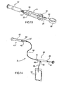
- the mixing unit 3 comprises a container 24, which is substantially in the shape of a syringe, defining the mixing chamber 21 and in which the compound can be prepared using the cartridge 4 as explained in the previous forms of embodiment.
- the dispensing unit 2 of the compound comprises, in this current form of embodiment, a drive element 41 for the piston 23 of the mixing unit 3 which can be remotely started, as will be made clearer further on. Such remote starting considerably reduces exposure of the operators to any radiation there may be in the area where the surgical operation is being performed.
- the drive element 41 represented in detail in figure 15 associated with the mixing unit 3, comprises a syringe element inside which a drive piston 42 slides in a hermetically sealed way, connected to a respective axial drive stem 43: the drive piston 42 defines, together with the sides of the syringe element, a drive chamber 44.
- the drive element 41 comprises a threaded opening 45 that connects to the mixing unit 3 while on the other end it comprises a tang 46 with an axial hole 47 allowing the drive chamber 44 to communicate with the outside.
- the dispensing unit 2 also comprises pumping means, indicated with 48, of a thrusting fluid for the drive piston 42: these pumping means 48 are suitable for making the drive stem 43 move in such a way that it presses the piston 23 of the mixing unit 3 and dispenses the compound during the surgical operation.
- pumping means 48 allows the command and the control of the compound dispensing to be located remotely so that the operators are in an area protected against radiation.
- the pumping means 48 comprise a hand pump 49 composed of a cylindrical chamber 50 inside which a manually operated plunger 51 slides.
- the cylindrical chamber 50 has a first fitting 52 which communicates with a tank 53 of fluid and a second fitting 54 which is coaxial to the cylindrical chamber 50.
- the tank 53 is composed of a disposable bag made in a known type of plastic material, containing a sterile physiological solution; a first pipe 55 connects the tank 53 to the first fitting 52 in a unidirectional way by means of, e.g., a check valve of the known type and not shown in the figures.
- a second pipe 56 connects in a unidirectional way by means of, e.g., a check valve of the known type and not shown in the figures -
- the mixer is used according to this form of embodiment.
- the mixing unit 3 is connected, in a sealed way, to the opening 45: in this way the end of the drive stem 43 is moved into contact with the piston 23 of the mixing unit 3.
- the plunger 51 is pulled towards the outside so the physiological solution can go from the tank 53 into the cylindrical chamber 50 through the first pipe 55.
- the physiological solution flows through the second pipe 56 so that the solution, having reached an appropriate pressure, makes the drive piston 42 move with the relative drive stem 43: in this way we have a thrusting action on the piston 23 of the mixing unit 3 which dispenses the compound inside, e.g., a syringe like the one described previously, or other means and/or devices provided for carrying out the operation and which are not the object of this invention.
- the pumping means 48 of the physiological solution comprise a remotely controllable electromechanical pump 58 which requires no manual work by the operators.
- this electromechanical pump 58 comprises a cylindrical chamber 50 similar to the one described in the previous form of embodiment, i.e. having a first communicating fitting with a first pipe 55 and a second communicating fitting 54 with a second pipe 56.
- a hermetically sealed plunger 51 slides inside the cylindrical chamber 50, the plunger 51 being associated with an electromechanical actuator 59, represented in detail in figure 17 and which, in turn, is fixed to the cylindrical chamber 50.
- the electromechanical actuator 59 comprises an electric motor 60 coupled to a screw mechanism of the type known, that acts on the plunger 51 which slides inside a cylindrical guide 61 integral with the motor 60.
- the motor 60 has a terminal 62 for the electrical connection, via cables 63, to a receiving station 64 of radio control signals emitted by a transmitting station, not represented in the figures but of the type known, and which is remotely operated by the operators.
- the first fitting 52 connects the cylindrical chamber 50 to a tank 53 of physiological solution, while the second fitting 54 hydraulically connects the cylindrical chamber 50 to the third fitting 57 on the drive element 40, already described.
- Another form of embodiment envisages one dispensing unit 2 of the compound comprising a drive element 41 that can be started remotely, suitable for exerting a thrust of pressure on the piston 23 of the mixing unit 3 so the compound can be dispensed.
- the dispensing unit 2 comprises an electromechanical actuator of the type similar to the one illustrated in figure 17 , interlocked to a receiving station like the one shown in figure 16 .
- the plunger 51 of the electromechanical actuator 59 can be connected mechanically to the drive piston 42 so that, subsequent to a suitable command signal received from a transmitting station, the drive stem 32 of the drive element 41 can press on the piston 23 and thus dispense the compound.
Landscapes
- Chemical & Material Sciences (AREA)
- Chemical Kinetics & Catalysis (AREA)
- Engineering & Computer Science (AREA)
- Aviation & Aerospace Engineering (AREA)
- Dispersion Chemistry (AREA)
- Infusion, Injection, And Reservoir Apparatuses (AREA)
- Mixers Of The Rotary Stirring Type (AREA)
- Dental Tools And Instruments Or Auxiliary Dental Instruments (AREA)
- Medical Preparation Storing Or Oral Administration Devices (AREA)
Claims (13)
- Procédé pour mélanger des composés diphasiques, comprenant un mélangeur comprenant une chambre (21) pour contenir une phase solide (22) et une cartouche (4) contenant une ampoule (18) d'une phase liquide (27), dans lequel ladite ampoule (18) est du type cassable, ladite chambre (21) et ladite cartouche (4) étant aptes à communiquer à travers des canaux respectifs (19, 20), dans lequel ladite cartouche (4) comprend une enveloppe externe (25) réalisée en un matériau déformable et élastique et a un volume interne (29) supérieur au volume occupé par ladite ampoule (18), comprenant les étapes suivantes :la rupture de ladite ampoule (18) de l'extérieur sur un point de rupture (28),la pression sur l'enveloppe externe (25) pour pomper et transférer ladite phase liquide (27) à l'intérieur de ladite chambre (21) à travers lesdits canaux (19, 20).
- Procédé selon la revendication 1, caractérisé en ce que ledit mélangeur comprend au moins une seringue (37) associable d'une manière amovible avec une unité de mélange (3), adaptée pour doser la quantité de composé à utiliser, ladite unité de mélange (3) comprenant un récipient (24), lequel est sensiblement sous la forme d'une seringue and définit ladite chambre (21).
- Procédé selon la revendication 2, caractérisé en ce que ladite seringue (37) comprend au moins un piston de distribution (39), coulissant axialement, qui définit au moins un volume de distribution (38) pour doser la quantité de composé à utiliser, et des éléments à vis (40) pour la connexion amovible et hermétique avec ladite unité de mélange (3).
- Procédé selon la revendication 1, comprenant une unité de mélange (3) et une unité de distribution (2) connectées fonctionnellement pour mélanger ladite phase liquide (27) et ladite phase solide (22) par le biais de moyens agitateurs agissant à l'intérieur de ladite chambre de mélange (21), et pour distribuer une quantité de composé diphasique mélangé à travers un canal (20) de ladite chambre (21), ladite unité de mélange (3) comprenant un récipient (24), lequel est sensiblement sous la forme d'une seringue and définit ladite chambre (21), dans lequel lesdits moyens agitateurs comprennent un agitateur (12) entraîné par une tige longitudinale (11) et dans lequel ledit mélangeur comprend un piston (23) coulissant longitudinalement sur commande le long de ladite chambre (21) et avec un trou (30) pour loger ladite tige (11) d'une manière coulissante.
- Procédé selon la revendication 4, caractérisé en ce que ladite unité de distribution (2) comprend une vis d'extrusion (6) ayant une cavité longitudinale (14) adaptée pour loger ladite tige (11) d'une manière coulissante et associable fonctionnellement avec ladite unité de mélange (3) pour commander le mouvement longitudinal du piston (23) le long de la chambre (21).
- Procédé selon la revendication 4 ou 5, caractérisé en ce que ladite unité de mélange (3) et ladite unité de distribution (2) sont connectées frontalement par l'intermédiaire de moyens à vis (9, 10).
- Procédé selon la revendication 4 ou 5, caractérisé en ce que ladite unité de mélange (3) et ladite unité de distribution (2) sont connectées par l'intermédiaire de moyens de verrouillage réciproque frontaux, par exemple des moyens d'accouplement à baïonnette.
- Procédé selon la revendication 4 ou 5, caractérisé en ce que ladite unité de mélange (3) et ladite unité de distribution (2) sont connectées par l'intermédiaire de moyens d'encliquetage latéraux.
- Procédé selon une des revendications 4 à 8, caractérisé en ce que ledit agitateur (12) est sous la forme d'une hélice.
- Procédé selon une des revendications 4 à 9, caractérisé en ce que ladite tige (11) comprend un bouton de préhension (13).
- Procédé selon une des revendications 4 à 10, caractérisé en ce que ladite unité de distribution (2) comprend un bouton (5) commandant ladite vis d'extrusion (6).
- Procédé selon une des revendications 4 à 11, caractérisé en ce que ladite unité de distribution (2) comprend une poignée (8).
- Procédé selon la revendication 1, caractérisé en ce que ladite chambre (21) et ladite cartouche (4) peuvent être connectées par l'intermédiaire de moyens à vis (16, 17).
Priority Applications (1)
| Application Number | Priority Date | Filing Date | Title |
|---|---|---|---|
| EP14197227.3A EP2881084B1 (fr) | 2009-02-06 | 2009-02-06 | Mélangeur de composés biphasiques et cartouche associé |
Applications Claiming Priority (1)
| Application Number | Priority Date | Filing Date | Title |
|---|---|---|---|
| PCT/IB2009/000220 WO2010089622A1 (fr) | 2009-02-06 | 2009-02-06 | Mélangeur de composés diphasiques |
Related Child Applications (2)
| Application Number | Title | Priority Date | Filing Date |
|---|---|---|---|
| EP14197227.3A Division EP2881084B1 (fr) | 2009-02-06 | 2009-02-06 | Mélangeur de composés biphasiques et cartouche associé |
| EP14197227.3A Division-Into EP2881084B1 (fr) | 2009-02-06 | 2009-02-06 | Mélangeur de composés biphasiques et cartouche associé |
Publications (2)
| Publication Number | Publication Date |
|---|---|
| EP2393456A1 EP2393456A1 (fr) | 2011-12-14 |
| EP2393456B1 true EP2393456B1 (fr) | 2015-01-21 |
Family
ID=41139060
Family Applications (2)
| Application Number | Title | Priority Date | Filing Date |
|---|---|---|---|
| EP14197227.3A Active EP2881084B1 (fr) | 2009-02-06 | 2009-02-06 | Mélangeur de composés biphasiques et cartouche associé |
| EP20090785803 Active EP2393456B1 (fr) | 2009-02-06 | 2009-02-06 | Mélangeur et procédé pour mélanger des composés diphasiques |
Family Applications Before (1)
| Application Number | Title | Priority Date | Filing Date |
|---|---|---|---|
| EP14197227.3A Active EP2881084B1 (fr) | 2009-02-06 | 2009-02-06 | Mélangeur de composés biphasiques et cartouche associé |
Country Status (6)
| Country | Link |
|---|---|
| US (1) | US9016925B2 (fr) |
| EP (2) | EP2881084B1 (fr) |
| KR (2) | KR101780914B1 (fr) |
| CN (1) | CN102307545B (fr) |
| ES (2) | ES2533790T3 (fr) |
| WO (1) | WO2010089622A1 (fr) |
Cited By (1)
| Publication number | Priority date | Publication date | Assignee | Title |
|---|---|---|---|---|
| EP4385613A1 (fr) | 2022-12-13 | 2024-06-19 | Heraeus Medical GmbH | Dispositif pour mélanger du ciment osseux |
Families Citing this family (14)
| Publication number | Priority date | Publication date | Assignee | Title |
|---|---|---|---|---|
| CN106290819B (zh) * | 2015-05-27 | 2018-06-19 | 艾博生物医药(杭州)有限公司 | 一种混合至少两种物质的装置 |
| ES2908654T3 (es) * | 2016-11-02 | 2022-05-03 | Miraki Innovation Think Tank Llc | Dispositivos para la generación de suspensión |
| US11324673B2 (en) | 2016-11-18 | 2022-05-10 | Miraki Innovation Think Tank Llc | Cosmetic appearance of skin |
| CA3059294A1 (fr) | 2017-04-05 | 2018-10-11 | Miraki Innovation Think Tank Llc | Production d'une suspension epaisse froide au point d'administration |
| BR112019020969A8 (pt) | 2017-04-05 | 2022-11-16 | Miraki Innovation Think Tank Llc | Contenção de pasta fluida fria |
| US10575887B2 (en) | 2017-08-04 | 2020-03-03 | Medtronic Holding Company Sàrl | Dispensing system and methods of use |
| US10981129B2 (en) * | 2017-08-07 | 2021-04-20 | Inventprise, Llc | Double chamber device for point of use mixing |
| US10500342B2 (en) * | 2017-08-21 | 2019-12-10 | Miraki Innovation Think Tank Llc | Cold slurry syringe |
| CN107595626B (zh) * | 2017-11-08 | 2020-07-24 | 周方敏 | 一种药剂吸入装置 |
| CN109604284B (zh) * | 2018-12-04 | 2021-10-08 | 钱俊 | 一种液压缸内壁清洁器 |
| US11197705B2 (en) * | 2019-07-24 | 2021-12-14 | Shao-Kang Hsueh | Bone cement injection device |
| CA3205655A1 (fr) | 2020-12-23 | 2022-06-30 | Tolmar International Limited | Systemes et procedes de combinaison d'ensembles valve de seringue |
| IT202100024638A1 (it) * | 2021-09-27 | 2023-03-27 | Tecres Spa | Dispositivo di miscelazione di almeno due composti |
| USD1029245S1 (en) | 2022-06-22 | 2024-05-28 | Tolmar International Limited | Syringe connector |
Family Cites Families (30)
| Publication number | Priority date | Publication date | Assignee | Title |
|---|---|---|---|---|
| US2908555A (en) * | 1955-07-15 | 1959-10-13 | Drager Otto H | Gas detecting device |
| US2831606A (en) * | 1956-11-16 | 1958-04-22 | Alters Merle Eugene | Method and device for kneading and removing a viscous material from its container |
| US3570486A (en) * | 1968-10-14 | 1971-03-16 | Horizon Ind Ltd | Mixing syringe |
| US3618216A (en) * | 1970-05-12 | 1971-11-09 | Charles G Jaeger | Process and apparatus for mixing and dispensing dental plaster |
| US3724077A (en) * | 1971-11-26 | 1973-04-03 | Unitek Corp | Mixing syringe |
| DE2913283C3 (de) * | 1979-04-03 | 1982-05-27 | Drägerwerk AG, 2400 Lübeck | Prüfröhrchen zur Messung von Chromat- und Chromsäure-Aerosolen in Luft |
| DE2948218C2 (de) * | 1979-11-30 | 1982-06-09 | Drägerwerk AG, 2400 Lübeck | Prüfröhrchen zur quantitativen Bestimmung von Schwefelsäure-Aerosolen |
| US4686192A (en) * | 1983-09-02 | 1987-08-11 | Electric Power Research Institute, Inc. | Method for detecting impurities in an oil sample |
| US4743229A (en) | 1986-09-29 | 1988-05-10 | Collagen Corporation | Collagen/mineral mixing device and method |
| IT1236864B (it) * | 1989-12-29 | 1993-04-22 | Tecres Spa | Procedimento per miscelare e somministrare direttamente in loco un cemento osseo a due componenti, e dispositivo che lo realizza |
| US5297698A (en) * | 1991-07-25 | 1994-03-29 | Minnesota Mining And Manufacturing Company | Two-stage mixing and dispensing assembly for preparations such as dental cements |
| DE19532015A1 (de) | 1995-08-31 | 1997-03-06 | Alfred Von Schuckmann | Vorrichtung zum Mischen und Ausbringen von Mehrkomponentenprodukten |
| US5876116A (en) * | 1996-11-15 | 1999-03-02 | Barker; Donald | Integrated bone cement mixing and dispensing system |
| US6116773A (en) * | 1999-01-22 | 2000-09-12 | Murray; William M. | Bone cement mixer and method |
| SE521945C2 (sv) * | 1999-02-26 | 2003-12-23 | Biomet Merck Cementing Technol | Blandningsanordning för framställning av bencement |
| US6984063B2 (en) * | 2002-10-07 | 2006-01-10 | Advanced Biomaterial Systems, Inc. | Apparatus for mixing and dispensing components |
| DE10152115A1 (de) * | 2001-10-23 | 2003-05-08 | Bosch Gmbh Robert | Vorrichtung zum Mischen mindestens zweier Fluide |
| ITVI20020140A1 (it) | 2002-06-26 | 2003-12-29 | Tecres Spa | Dispositivo per il dosaggio manuale di un fluido medicale particolarmente cemento osseo |
| DE10242984B4 (de) * | 2002-09-17 | 2010-09-23 | Sanatis Gmbh | Vorrichtung zum Herstellen von Gemischen aus zwei Komponenten |
| GB2398741B (en) * | 2003-02-05 | 2005-04-13 | Summit Medical Ltd | Orthopaedic cement mixing device |
| ITMO20030057A1 (it) * | 2003-03-04 | 2004-09-05 | Sidam Di Azzolini Graziano E C S A S | Dispositivo per la confezione, la miscelazione e l'applicazione di cemento osseo. |
| BRPI0413681A (pt) | 2003-08-21 | 2006-10-24 | Mixpac Systems Ag | dispositivo e processo para armazenar, misturar e dispensar componentes |
| US20050105384A1 (en) * | 2003-11-18 | 2005-05-19 | Scimed Life Systems, Inc. | Apparatus for mixing and dispensing a multi-component bone cement |
| US7524103B2 (en) * | 2003-11-18 | 2009-04-28 | Boston Scientific Scimed, Inc. | Apparatus for mixing and dispensing a multi-component bone cement |
| US7441652B2 (en) * | 2004-05-20 | 2008-10-28 | Med Institute, Inc. | Mixing system |
| US8038682B2 (en) * | 2004-08-17 | 2011-10-18 | Boston Scientific Scimed, Inc. | Apparatus and methods for delivering compounds into vertebrae for vertebroplasty |
| ITVI20050152A1 (it) | 2005-05-20 | 2006-11-21 | Tecres Spa | Cartuccia per la conservazione e l'erogazione sterile di un composto bifasico, particolarmente per una resina acrilica |
| ITVI20050187A1 (it) * | 2005-06-28 | 2006-12-29 | Tecres Spa | Cartuccia per la miscelazione sterile di un composto bifasico, perticolarmente per resine acriliche bicomponenti |
| CN101415483A (zh) * | 2006-02-10 | 2009-04-22 | 陶氏环球技术公司 | 可伸缩销混合样品成形设备和方法 |
| EP2898942B1 (fr) * | 2006-10-06 | 2016-09-14 | Stryker Corporation | Mélange de ciment osseux motorisé et système d'administration qui permet à un utilisateur de détacher le dispositif d'administration à partir du mélangeur pour distribution |
-
2009
- 2009-02-06 EP EP14197227.3A patent/EP2881084B1/fr active Active
- 2009-02-06 KR KR1020167028250A patent/KR101780914B1/ko active IP Right Grant
- 2009-02-06 WO PCT/IB2009/000220 patent/WO2010089622A1/fr active Application Filing
- 2009-02-06 KR KR1020117018280A patent/KR101832498B1/ko active IP Right Grant
- 2009-02-06 US US13/148,185 patent/US9016925B2/en active Active
- 2009-02-06 ES ES09785803.9T patent/ES2533790T3/es active Active
- 2009-02-06 CN CN200980156166.XA patent/CN102307545B/zh active Active
- 2009-02-06 EP EP20090785803 patent/EP2393456B1/fr active Active
- 2009-02-06 ES ES14197227.3T patent/ES2614459T3/es active Active
Cited By (1)
| Publication number | Priority date | Publication date | Assignee | Title |
|---|---|---|---|---|
| EP4385613A1 (fr) | 2022-12-13 | 2024-06-19 | Heraeus Medical GmbH | Dispositif pour mélanger du ciment osseux |
Also Published As
| Publication number | Publication date |
|---|---|
| CN102307545A (zh) | 2012-01-04 |
| KR101780914B1 (ko) | 2017-10-10 |
| EP2881084B1 (fr) | 2016-11-16 |
| EP2393456A1 (fr) | 2011-12-14 |
| CN102307545B (zh) | 2016-06-15 |
| US9016925B2 (en) | 2015-04-28 |
| KR20110111467A (ko) | 2011-10-11 |
| ES2614459T3 (es) | 2017-05-31 |
| WO2010089622A1 (fr) | 2010-08-12 |
| US20120092951A1 (en) | 2012-04-19 |
| ES2533790T3 (es) | 2015-04-14 |
| KR101832498B1 (ko) | 2018-02-26 |
| KR20160124235A (ko) | 2016-10-26 |
| EP2881084A1 (fr) | 2015-06-10 |
Similar Documents
| Publication | Publication Date | Title |
|---|---|---|
| EP2393456B1 (fr) | Mélangeur et procédé pour mélanger des composés diphasiques | |
| US9643139B2 (en) | Supply unit for a mixer of two-phase compounds | |
| EP2066432B1 (fr) | Système de mélange et d'administration de ciment osseux et de transfert automatique du ciment entre un malaxeur et un système d'administration | |
| CA2972484C (fr) | Applicateur de ciment orthopedique a vanne a trois voies servant a liberer la pression | |
| WO2007139758A2 (fr) | Délivrance de compositions de plusieurs composants | |
| US9968392B2 (en) | Method and assembly for preparing and dispensing a paste | |
| EP3265016B1 (fr) | Système d'alimentation de matériaux dentaires | |
| KR20180037184A (ko) | 유압 압출 시스템 |
Legal Events
| Date | Code | Title | Description |
|---|---|---|---|
| PUAI | Public reference made under article 153(3) epc to a published international application that has entered the european phase |
Free format text: ORIGINAL CODE: 0009012 |
|
| 17P | Request for examination filed |
Effective date: 20110906 |
|
| AK | Designated contracting states |
Kind code of ref document: A1 Designated state(s): AT BE BG CH CY CZ DE DK EE ES FI FR GB GR HR HU IE IS IT LI LT LU LV MC MK MT NL NO PL PT RO SE SI SK TR |
|
| DAX | Request for extension of the european patent (deleted) | ||
| 17Q | First examination report despatched |
Effective date: 20120921 |
|
| GRAP | Despatch of communication of intention to grant a patent |
Free format text: ORIGINAL CODE: EPIDOSNIGR1 |
|
| INTG | Intention to grant announced |
Effective date: 20140219 |
|
| GRAS | Grant fee paid |
Free format text: ORIGINAL CODE: EPIDOSNIGR3 |
|
| GRAP | Despatch of communication of intention to grant a patent |
Free format text: ORIGINAL CODE: EPIDOSNIGR1 |
|
| INTG | Intention to grant announced |
Effective date: 20140731 |
|
| GRAA | (expected) grant |
Free format text: ORIGINAL CODE: 0009210 |
|
| AK | Designated contracting states |
Kind code of ref document: B1 Designated state(s): AT BE BG CH CY CZ DE DK EE ES FI FR GB GR HR HU IE IS IT LI LT LU LV MC MK MT NL NO PL PT RO SE SI SK TR |
|
| REG | Reference to a national code |
Ref country code: GB Ref legal event code: FG4D |
|
| REG | Reference to a national code |
Ref country code: CH Ref legal event code: EP |
|
| REG | Reference to a national code |
Ref country code: IE Ref legal event code: FG4D |
|
| REG | Reference to a national code |
Ref country code: DE Ref legal event code: R096 Ref document number: 602009029125 Country of ref document: DE Effective date: 20150305 |
|
| REG | Reference to a national code |
Ref country code: AT Ref legal event code: REF Ref document number: 708808 Country of ref document: AT Kind code of ref document: T Effective date: 20150315 |
|
| REG | Reference to a national code |
Ref country code: ES Ref legal event code: FG2A Ref document number: 2533790 Country of ref document: ES Kind code of ref document: T3 Effective date: 20150414 |
|
| REG | Reference to a national code |
Ref country code: NL Ref legal event code: VDEP Effective date: 20150121 |
|
| REG | Reference to a national code |
Ref country code: AT Ref legal event code: MK05 Ref document number: 708808 Country of ref document: AT Kind code of ref document: T Effective date: 20150121 |
|
| REG | Reference to a national code |
Ref country code: LT Ref legal event code: MG4D |
|
| PG25 | Lapsed in a contracting state [announced via postgrant information from national office to epo] |
Ref country code: BE Free format text: LAPSE BECAUSE OF NON-PAYMENT OF DUE FEES Effective date: 20150228 |
|
| PG25 | Lapsed in a contracting state [announced via postgrant information from national office to epo] |
Ref country code: LT Free format text: LAPSE BECAUSE OF FAILURE TO SUBMIT A TRANSLATION OF THE DESCRIPTION OR TO PAY THE FEE WITHIN THE PRESCRIBED TIME-LIMIT Effective date: 20150121 Ref country code: NO Free format text: LAPSE BECAUSE OF FAILURE TO SUBMIT A TRANSLATION OF THE DESCRIPTION OR TO PAY THE FEE WITHIN THE PRESCRIBED TIME-LIMIT Effective date: 20150421 Ref country code: FI Free format text: LAPSE BECAUSE OF FAILURE TO SUBMIT A TRANSLATION OF THE DESCRIPTION OR TO PAY THE FEE WITHIN THE PRESCRIBED TIME-LIMIT Effective date: 20150121 Ref country code: BG Free format text: LAPSE BECAUSE OF FAILURE TO SUBMIT A TRANSLATION OF THE DESCRIPTION OR TO PAY THE FEE WITHIN THE PRESCRIBED TIME-LIMIT Effective date: 20150421 Ref country code: SE Free format text: LAPSE BECAUSE OF FAILURE TO SUBMIT A TRANSLATION OF THE DESCRIPTION OR TO PAY THE FEE WITHIN THE PRESCRIBED TIME-LIMIT Effective date: 20150121 Ref country code: HR Free format text: LAPSE BECAUSE OF FAILURE TO SUBMIT A TRANSLATION OF THE DESCRIPTION OR TO PAY THE FEE WITHIN THE PRESCRIBED TIME-LIMIT Effective date: 20150121 |
|
| PG25 | Lapsed in a contracting state [announced via postgrant information from national office to epo] |
Ref country code: PL Free format text: LAPSE BECAUSE OF FAILURE TO SUBMIT A TRANSLATION OF THE DESCRIPTION OR TO PAY THE FEE WITHIN THE PRESCRIBED TIME-LIMIT Effective date: 20150121 Ref country code: IS Free format text: LAPSE BECAUSE OF FAILURE TO SUBMIT A TRANSLATION OF THE DESCRIPTION OR TO PAY THE FEE WITHIN THE PRESCRIBED TIME-LIMIT Effective date: 20150521 Ref country code: GR Free format text: LAPSE BECAUSE OF FAILURE TO SUBMIT A TRANSLATION OF THE DESCRIPTION OR TO PAY THE FEE WITHIN THE PRESCRIBED TIME-LIMIT Effective date: 20150422 Ref country code: NL Free format text: LAPSE BECAUSE OF FAILURE TO SUBMIT A TRANSLATION OF THE DESCRIPTION OR TO PAY THE FEE WITHIN THE PRESCRIBED TIME-LIMIT Effective date: 20150121 Ref country code: LV Free format text: LAPSE BECAUSE OF FAILURE TO SUBMIT A TRANSLATION OF THE DESCRIPTION OR TO PAY THE FEE WITHIN THE PRESCRIBED TIME-LIMIT Effective date: 20150121 Ref country code: AT Free format text: LAPSE BECAUSE OF FAILURE TO SUBMIT A TRANSLATION OF THE DESCRIPTION OR TO PAY THE FEE WITHIN THE PRESCRIBED TIME-LIMIT Effective date: 20150121 |
|
| REG | Reference to a national code |
Ref country code: CH Ref legal event code: PL |
|
| REG | Reference to a national code |
Ref country code: DE Ref legal event code: R097 Ref document number: 602009029125 Country of ref document: DE |
|
| PG25 | Lapsed in a contracting state [announced via postgrant information from national office to epo] |
Ref country code: CZ Free format text: LAPSE BECAUSE OF FAILURE TO SUBMIT A TRANSLATION OF THE DESCRIPTION OR TO PAY THE FEE WITHIN THE PRESCRIBED TIME-LIMIT Effective date: 20150121 Ref country code: LI Free format text: LAPSE BECAUSE OF NON-PAYMENT OF DUE FEES Effective date: 20150228 Ref country code: SK Free format text: LAPSE BECAUSE OF FAILURE TO SUBMIT A TRANSLATION OF THE DESCRIPTION OR TO PAY THE FEE WITHIN THE PRESCRIBED TIME-LIMIT Effective date: 20150121 Ref country code: DK Free format text: LAPSE BECAUSE OF FAILURE TO SUBMIT A TRANSLATION OF THE DESCRIPTION OR TO PAY THE FEE WITHIN THE PRESCRIBED TIME-LIMIT Effective date: 20150121 Ref country code: MC Free format text: LAPSE BECAUSE OF FAILURE TO SUBMIT A TRANSLATION OF THE DESCRIPTION OR TO PAY THE FEE WITHIN THE PRESCRIBED TIME-LIMIT Effective date: 20150121 Ref country code: EE Free format text: LAPSE BECAUSE OF FAILURE TO SUBMIT A TRANSLATION OF THE DESCRIPTION OR TO PAY THE FEE WITHIN THE PRESCRIBED TIME-LIMIT Effective date: 20150121 Ref country code: CH Free format text: LAPSE BECAUSE OF NON-PAYMENT OF DUE FEES Effective date: 20150228 Ref country code: RO Free format text: LAPSE BECAUSE OF FAILURE TO SUBMIT A TRANSLATION OF THE DESCRIPTION OR TO PAY THE FEE WITHIN THE PRESCRIBED TIME-LIMIT Effective date: 20150121 |
|
| REG | Reference to a national code |
Ref country code: IE Ref legal event code: MM4A |
|
| PLBE | No opposition filed within time limit |
Free format text: ORIGINAL CODE: 0009261 |
|
| STAA | Information on the status of an ep patent application or granted ep patent |
Free format text: STATUS: NO OPPOSITION FILED WITHIN TIME LIMIT |
|
| REG | Reference to a national code |
Ref country code: HU Ref legal event code: AG4A Ref document number: E024396 Country of ref document: HU |
|
| 26N | No opposition filed |
Effective date: 20151022 |
|
| REG | Reference to a national code |
Ref country code: FR Ref legal event code: PLFP Year of fee payment: 8 |
|
| PG25 | Lapsed in a contracting state [announced via postgrant information from national office to epo] |
Ref country code: IE Free format text: LAPSE BECAUSE OF NON-PAYMENT OF DUE FEES Effective date: 20150206 |
|
| PG25 | Lapsed in a contracting state [announced via postgrant information from national office to epo] |
Ref country code: SI Free format text: LAPSE BECAUSE OF FAILURE TO SUBMIT A TRANSLATION OF THE DESCRIPTION OR TO PAY THE FEE WITHIN THE PRESCRIBED TIME-LIMIT Effective date: 20150121 |
|
| PG25 | Lapsed in a contracting state [announced via postgrant information from national office to epo] |
Ref country code: BE Free format text: LAPSE BECAUSE OF FAILURE TO SUBMIT A TRANSLATION OF THE DESCRIPTION OR TO PAY THE FEE WITHIN THE PRESCRIBED TIME-LIMIT Effective date: 20150121 |
|
| PG25 | Lapsed in a contracting state [announced via postgrant information from national office to epo] |
Ref country code: MT Free format text: LAPSE BECAUSE OF FAILURE TO SUBMIT A TRANSLATION OF THE DESCRIPTION OR TO PAY THE FEE WITHIN THE PRESCRIBED TIME-LIMIT Effective date: 20150121 |
|
| REG | Reference to a national code |
Ref country code: FR Ref legal event code: PLFP Year of fee payment: 9 |
|
| PG25 | Lapsed in a contracting state [announced via postgrant information from national office to epo] |
Ref country code: CY Free format text: LAPSE BECAUSE OF FAILURE TO SUBMIT A TRANSLATION OF THE DESCRIPTION OR TO PAY THE FEE WITHIN THE PRESCRIBED TIME-LIMIT Effective date: 20150121 |
|
| PG25 | Lapsed in a contracting state [announced via postgrant information from national office to epo] |
Ref country code: PT Free format text: LAPSE BECAUSE OF FAILURE TO SUBMIT A TRANSLATION OF THE DESCRIPTION OR TO PAY THE FEE WITHIN THE PRESCRIBED TIME-LIMIT Effective date: 20150521 |
|
| PG25 | Lapsed in a contracting state [announced via postgrant information from national office to epo] |
Ref country code: TR Free format text: LAPSE BECAUSE OF FAILURE TO SUBMIT A TRANSLATION OF THE DESCRIPTION OR TO PAY THE FEE WITHIN THE PRESCRIBED TIME-LIMIT Effective date: 20150121 |
|
| PG25 | Lapsed in a contracting state [announced via postgrant information from national office to epo] |
Ref country code: LU Free format text: LAPSE BECAUSE OF NON-PAYMENT OF DUE FEES Effective date: 20150206 |
|
| REG | Reference to a national code |
Ref country code: FR Ref legal event code: PLFP Year of fee payment: 10 |
|
| PG25 | Lapsed in a contracting state [announced via postgrant information from national office to epo] |
Ref country code: MK Free format text: LAPSE BECAUSE OF FAILURE TO SUBMIT A TRANSLATION OF THE DESCRIPTION OR TO PAY THE FEE WITHIN THE PRESCRIBED TIME-LIMIT Effective date: 20150121 |
|
| PGFP | Annual fee paid to national office [announced via postgrant information from national office to epo] |
Ref country code: HU Payment date: 20190215 Year of fee payment: 11 |
|
| PG25 | Lapsed in a contracting state [announced via postgrant information from national office to epo] |
Ref country code: HU Free format text: LAPSE BECAUSE OF NON-PAYMENT OF DUE FEES Effective date: 20200207 |
|
| P01 | Opt-out of the competence of the unified patent court (upc) registered |
Effective date: 20230509 |
|
| PGFP | Annual fee paid to national office [announced via postgrant information from national office to epo] |
Ref country code: ES Payment date: 20240301 Year of fee payment: 16 |
|
| PGFP | Annual fee paid to national office [announced via postgrant information from national office to epo] |
Ref country code: DE Payment date: 20240123 Year of fee payment: 16 Ref country code: GB Payment date: 20240123 Year of fee payment: 16 |
|
| PGFP | Annual fee paid to national office [announced via postgrant information from national office to epo] |
Ref country code: IT Payment date: 20240123 Year of fee payment: 16 Ref country code: FR Payment date: 20240123 Year of fee payment: 16 |