EP2393181A1 - Commutation pour un système de transmission d'énergie sans contact et inductif - Google Patents
Commutation pour un système de transmission d'énergie sans contact et inductif Download PDFInfo
- Publication number
- EP2393181A1 EP2393181A1 EP10005752A EP10005752A EP2393181A1 EP 2393181 A1 EP2393181 A1 EP 2393181A1 EP 10005752 A EP10005752 A EP 10005752A EP 10005752 A EP10005752 A EP 10005752A EP 2393181 A1 EP2393181 A1 EP 2393181A1
- Authority
- EP
- European Patent Office
- Prior art keywords
- converter
- circuit
- primary
- voltage
- circuit according
- Prior art date
- Legal status (The legal status is an assumption and is not a legal conclusion. Google has not performed a legal analysis and makes no representation as to the accuracy of the status listed.)
- Granted
Links
- 230000001939 inductive effect Effects 0.000 title claims abstract description 19
- 238000012546 transfer Methods 0.000 title claims description 13
- 230000005540 biological transmission Effects 0.000 claims abstract description 14
- 238000011105 stabilization Methods 0.000 claims abstract description 12
- 239000003990 capacitor Substances 0.000 claims description 11
- 238000012937 correction Methods 0.000 claims description 8
- 238000003860 storage Methods 0.000 claims description 6
- 230000003750 conditioning effect Effects 0.000 claims description 4
- 238000009499 grossing Methods 0.000 claims description 3
- 230000001105 regulatory effect Effects 0.000 claims description 3
- 238000009877 rendering Methods 0.000 claims 2
- 238000000605 extraction Methods 0.000 claims 1
- 238000002955 isolation Methods 0.000 claims 1
- 230000036962 time dependent Effects 0.000 claims 1
- 238000000926 separation method Methods 0.000 abstract 1
- 230000008878 coupling Effects 0.000 description 19
- 238000010168 coupling process Methods 0.000 description 19
- 238000005859 coupling reaction Methods 0.000 description 19
- 238000013459 approach Methods 0.000 description 13
- 239000000306 component Substances 0.000 description 9
- 238000013461 design Methods 0.000 description 9
- 238000007667 floating Methods 0.000 description 7
- 230000001965 increasing effect Effects 0.000 description 4
- 238000002360 preparation method Methods 0.000 description 3
- 238000011161 development Methods 0.000 description 2
- 238000005516 engineering process Methods 0.000 description 2
- 230000003287 optical effect Effects 0.000 description 2
- 238000012545 processing Methods 0.000 description 2
- 239000004065 semiconductor Substances 0.000 description 2
- 229910005580 NiCd Inorganic materials 0.000 description 1
- 238000004364 calculation method Methods 0.000 description 1
- 230000000052 comparative effect Effects 0.000 description 1
- 238000010276 construction Methods 0.000 description 1
- 239000008358 core component Substances 0.000 description 1
- 230000007423 decrease Effects 0.000 description 1
- 238000010586 diagram Methods 0.000 description 1
- 230000000694 effects Effects 0.000 description 1
- 238000004146 energy storage Methods 0.000 description 1
- 230000007613 environmental effect Effects 0.000 description 1
- 239000002360 explosive Substances 0.000 description 1
- 238000011835 investigation Methods 0.000 description 1
- 229910001416 lithium ion Inorganic materials 0.000 description 1
- 238000004519 manufacturing process Methods 0.000 description 1
- 238000000034 method Methods 0.000 description 1
- 238000012986 modification Methods 0.000 description 1
- 230000004048 modification Effects 0.000 description 1
- 239000013307 optical fiber Substances 0.000 description 1
- 230000003071 parasitic effect Effects 0.000 description 1
- 230000035515 penetration Effects 0.000 description 1
- 230000001360 synchronised effect Effects 0.000 description 1
- 239000012780 transparent material Substances 0.000 description 1
- 238000004804 winding Methods 0.000 description 1
Images


Classifications
-
- H—ELECTRICITY
- H02—GENERATION; CONVERSION OR DISTRIBUTION OF ELECTRIC POWER
- H02J—CIRCUIT ARRANGEMENTS OR SYSTEMS FOR SUPPLYING OR DISTRIBUTING ELECTRIC POWER; SYSTEMS FOR STORING ELECTRIC ENERGY
- H02J50/00—Circuit arrangements or systems for wireless supply or distribution of electric power
- H02J50/10—Circuit arrangements or systems for wireless supply or distribution of electric power using inductive coupling
- H02J50/12—Circuit arrangements or systems for wireless supply or distribution of electric power using inductive coupling of the resonant type
-
- H—ELECTRICITY
- H02—GENERATION; CONVERSION OR DISTRIBUTION OF ELECTRIC POWER
- H02J—CIRCUIT ARRANGEMENTS OR SYSTEMS FOR SUPPLYING OR DISTRIBUTING ELECTRIC POWER; SYSTEMS FOR STORING ELECTRIC ENERGY
- H02J7/00—Circuit arrangements for charging or depolarising batteries or for supplying loads from batteries
- H02J7/0029—Circuit arrangements for charging or depolarising batteries or for supplying loads from batteries with safety or protection devices or circuits
- H02J7/00308—Overvoltage protection
-
- H—ELECTRICITY
- H04—ELECTRIC COMMUNICATION TECHNIQUE
- H04B—TRANSMISSION
- H04B5/00—Near-field transmission systems, e.g. inductive or capacitive transmission systems
- H04B5/70—Near-field transmission systems, e.g. inductive or capacitive transmission systems specially adapted for specific purposes
- H04B5/79—Near-field transmission systems, e.g. inductive or capacitive transmission systems specially adapted for specific purposes for data transfer in combination with power transfer
Definitions
- the present invention relates to a circuit for a system for contactless, inductive power transmission, in particular for use in the power supply of mobile devices and to an associated charging circuit.
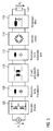
- Fig. 1 The basic subdivision of a system for inductive energy transfer is in Fig. 1 shown.
- Core component in the case of contactless, inductive energy transfer is a loosely coupled transformer, which represents the magnetic coupling of a coil in the base part 102 with a coil in the handset 104 on circuitry level.
- the energy transfer between base and handset takes place.
- this energy can be used to enable the functionality of the handset, on the other hand it can be used in accumulators (for modern applications mostly Li-Lonen batteries, but there are also other types of batteries such as lead, NiCd, NiMh).
- Types etc. can be temporarily stored. Will the handset 104 as in Fig. 1 (b) shown removed from the base station 102, the energy transfer is interrupted. The handset 104 is then powered from the previously charged internal energy storage or dwells in an inactive state until the next contact with the base 102.
- the most well-known example of such an inductive charging system is the electric toothbrush, which makes it possible to charge the toothbrush as a mobile part 104 without a galvanic connection.
- the current state of the art in the application of IE usually includes a signal feedback between power sink and source, whereby the current electrical state of the galvanically isolated secondary side on the primary side is known in any form.
- This information is used on the primary side to respond to a change in the secondary load by changing a manipulated variable (switching frequency, duty cycle, etc.) on the primary side.
- This technical approach requires the provision of a channel to transmit this information.
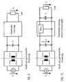
- Known technical realizations, eg DE 3902618 A1 . DE 101 58 794 B4 . US Pat. No. 6,912,137 B2 use a separate physical channel for this signal feedback, as shown in Fig. 2 is shown.
- the basic structure of the power section of a system based on a resonant DC-DC converter for IE is in Fig. 5 shown.
- This type of converter is to be considered in the context of inductive energy transmission as prior art.
- other converter types based on a transformer are conceivable (flyback, forward, Cuk, asymmetric half-bridge, etc.).
- the input voltage V is chopped by a switch bridge 106 into a high-frequency AC voltage.
- This switch bridge 106 may consist of a full or half bridge, wherein semiconductor switches are used as active components.
- This AC voltage is applied to the primary side of the loosely coupled transformer 110.
- blind elements which are shown schematically as resonant circuits 108 and 112.
- a series capacitance is inserted on the primary side, but it is also possible to provide a plurality of reactive elements for selectively influencing the frequency characteristics of the primary circuit.
- LLC additional reactive elements
- LLCC main inductance of the transformer
- the secondary current is rectified on the output side.
- the rectification 114 can be designed as full-wave or half-wave rectification, as components both regular diodes and semiconductor switches can be used (synchronous rectification).
- the rectified output current is smoothed by means of a filter 116 (inductance optional).
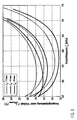
- the current state of the art uses a feedback signal to realize a desired-actual-value comparison by z. B. in the case of the resonant converter track the switching frequency as a manipulated variable of the controlled system.
- a change in the output load is also a change in the output load, if the switching frequency is selected as a fixed value, as from the intersection of the dashed curves Fig. 6 evident. Accordingly, this special operating point can only be used to a very limited extent from the point of view of as constant an output voltage as possible. In particular, a direct supply of sensitive loads with a very narrow range of values of the permissible load voltage with a fixed selection of the switching frequency is thus impossible.
- the efficiency of the IE system in this area is very sensitive to distance variations.
- the positioning is severely limited in systems utilizing the coupling-independent point and care must be taken under efficiency aspects that not too large distance variations from the nominal distance are possible.
- the present invention is based on the idea of eliminating signal feedback by dropping the requirement of a stabilized output voltage.
- the resonant stage is operated fixed frequency, the choice of the switching frequency in contrast to previously known approaches can in principle be arbitrary. With regard to minimum losses, however, there is an excellent optimum for this parameter, see also the above statements.
- the free choice of the switching frequency therefore simplifies the design of the resonant converter stage considerably. Moreover, this approach allows a targeted optimal design of this stage.
- the present invention proposes an extension to a two-stage concept.
- the second stage of the preparation of the secondary-side output voltage V o is used .
- the block diagram of such post-stabilization is in Fig. 9 shown.
- the present invention advantageously makes it possible completely to dispense with a separate signal feedback in order to make the construction of the magnetic coupling between primary and secondary side technically as simple as possible.
- the design can be made with the highest possible priority on the energy transfer and there must be no technical compromises or complex demodulation circuits are taken into account.
- the resonant LLC converter is used only to ensure the ZVS operation of the so-called " electronic transformer” .
- no classical transformer is used, in which the air gap between quasi zero and a maximum value can be fixed. Rather, it is loosely coupled coils, which can only be approximated to a minimum distance. This is not adjustable to any small value. Accordingly, as a developer of a system for inductive energy transmission system-related with a, even under optimal conditions, very low magnetizing inductance L m and a very high leakage inductance L res to fight.
- the present invention therefore proposes a circuit for a system for contactless, inductive energy transmission, in particular for use in the power supply of mobile devices.
- a primary-side circuit is arranged on a primary side and can be connected to a primary-side supply voltage
- a secondary-side circuit is arranged on a secondary side and can be connected to a load to be supplied with energy.
- a galvanically isolated transmitter stage for contactlessly transferring energy from the primary side across an air gap to the secondary, wherein at least two magnetically coupled inductive energy transfer coils are provided, which are physically separable by removing the secondary from the primary side are.
- the transformer stage has a resonant converter and the secondary-side circuit further comprises a Nachstabilmaschineseck.
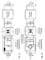
- the Nachstabilmaschinestress according to the present invention may be designed as a simple linear regulator or as a switched mode power supply, as shown in Fig. 10 and Fig. 11 is shown. Moreover, an even simpler overvoltage limitation as the only "voltage control" is conceivable. Both the linear regulator and the switching power supply for restabilization can be implemented as an integrated module or constructed from discrete components.
- the buck converter For the use of a clocked power supply for the Nachstabilmaschine come a variety of DC-DC converters in question, in particular in this context, the buck converter, the buck-boost converter, the Cuk converter and the boost converter called. It is also possible to use galvanically separated converters, such as the flyback or forward converter, as well as load-resonant or switch-resonant converters. For very insensitive loads, only a simple overvoltage limitation can be provided.
- the overcoming of the air gap can preferably take place, among other realizations already mentioned, with the aid of resonant converters, as shown in FIG Fig. 5 is shown.
- the parasitic properties of the loosely coupled transformer can be compensated. Both on the primary side and on the secondary side, a series or parallel compensation can be performed (capacitor). On the secondary side, this compensation can also be omitted.
- other reactive elements can also be provided for selectively influencing the frequency characteristics of the resonant circuit.
- this DC voltage can be provided directly by a battery or by a DC-DC converter, as in Fig. 14 and Fig. 15 shown.
- boost converters which are illustrated by way of example can also use different DC-DC converters (Buck, Buck Boost, Flyback, Forward, Cuk, etc.). Is the input voltage V; as a DC voltage system-conditioned not available from the outset, it must first from another source voltage, as in Fig. 15 illustrated, processed. Accordingly, the proposed concept of a two-stage overcoming of the air gap usually requires a third stage for conditioning the input voltage.
- the DC voltage V g can also be generated by rectifying the mains voltage by means of a bridge rectifier with storage capacitor.
- the rectified and smoothed line voltage in this case serves as the input voltage of a DC-DC converter, which compensates for the resulting ripple (double mains frequency) and provides a stabilized output voltage.
- This stabilized DC voltage in turn serves the converter stage to overcome the air gap as an input voltage.
- boost converter also any other topologies such.
- the buck converter can be used.
- a passive power factor correction can be provided (smoothing reactor).
- an active power factor correction may be made to generate V i .
- the resonant intermediate can also be supplied directly from a rectified alternating network, as in Fig. 17 shown schematically.
- This in turn operates as a fixed frequency electronic transformer and additionally improves the network-side power factor compared to a rectifier bridge in combination with a storage capacitor.
- the illustrated capacitor C HF has a small nominal value.
- a storage capacitor electrolytic capacitor
- it can not buffer significant energy, but only serves to filter the high-frequency harmonics of the input current of the converter stage to overcome the air gap.
- a voltage ripple arises on the output voltage V o at twice the line frequency.
- this residual ripple is again compensated by the post-stabilization stage on the secondary side.
- Resonant converters were identified as the favored topology for overcoming the air gap.
- Preferred basic structures of the resonant circuits are in the FIGS. 18 to 20 shown.
- the structure of the resonant circuit of the resonant converter differs by the presence and placement of a capacitor on the secondary side.
- the use of a full bridge for rectification is advantageous, otherwise the secondary side can also be used as center tap (see Fig. 19 ) to minimize the diode losses that occur.
- the post-stabilization is in Fig. 18 realized by a buck converter.
- a buck-boost converter was selected as the topology for restabilization.
- a boost converter as in Fig. 20 shown, can be used.
- the post-stabilization stage is realized by way of example by means of a buck converter, but as already mentioned, different variants of the post-stabilization can be used. Likewise, different resonant circuit topologies are possible.
- Fig. 21 the processing of the input-side mains voltage takes place with the aid of a simple rectifier bridge in conjunction with a storage capacitor. This smoothes the rectified mains voltage and charges in a first approximation to the peak value of the mains voltage.
- the resulting voltage ripple of the secondary-side output voltage V o of the resonant stage is regulated (in addition to the voltage variation due to different positional relationships) by the post-stabilization stage.
- a passive power factor correction can be provided as described in Fig. 22 is shown schematically.
- the recharging pulses are widened by additional impedances (usually inductive), whereby the recorded distortion reactive power decreases and the power factor increases.
- the smoothing inductor L PFC is used in particular for the passive PFC .
- a boost converter was chosen by way of example.
Landscapes
- Engineering & Computer Science (AREA)
- Power Engineering (AREA)
- Computer Networks & Wireless Communication (AREA)
- Signal Processing (AREA)
- Dc-Dc Converters (AREA)
- Charge And Discharge Circuits For Batteries Or The Like (AREA)
- Secondary Cells (AREA)
Priority Applications (5)
| Application Number | Priority Date | Filing Date | Title |
|---|---|---|---|
| EP10005752.0A EP2393181B1 (fr) | 2010-06-02 | 2010-06-02 | Commutation pour un système de transmission d'énergie sans contact et inductif |
| PCT/EP2011/002637 WO2011151038A1 (fr) | 2010-06-02 | 2011-05-27 | Montage pour un système de transfert d'énergie par induction, sans contact |
| US13/701,756 US9502921B2 (en) | 2010-06-02 | 2011-05-27 | Circuit for a system for contactless inductive power transmission |
| CN201180038028.9A CN103210559B (zh) | 2010-06-02 | 2011-05-27 | 用于非接触式感应能量传输系统的电路 |
| JP2013512787A JP5550785B2 (ja) | 2010-06-02 | 2011-05-27 | 非接触型の誘導電力伝送システムの回路 |
Applications Claiming Priority (1)
| Application Number | Priority Date | Filing Date | Title |
|---|---|---|---|
| EP10005752.0A EP2393181B1 (fr) | 2010-06-02 | 2010-06-02 | Commutation pour un système de transmission d'énergie sans contact et inductif |
Publications (2)
| Publication Number | Publication Date |
|---|---|
| EP2393181A1 true EP2393181A1 (fr) | 2011-12-07 |
| EP2393181B1 EP2393181B1 (fr) | 2019-09-04 |
Family
ID=42782298
Family Applications (1)
| Application Number | Title | Priority Date | Filing Date |
|---|---|---|---|
| EP10005752.0A Active EP2393181B1 (fr) | 2010-06-02 | 2010-06-02 | Commutation pour un système de transmission d'énergie sans contact et inductif |
Country Status (5)
| Country | Link |
|---|---|
| US (1) | US9502921B2 (fr) |
| EP (1) | EP2393181B1 (fr) |
| JP (1) | JP5550785B2 (fr) |
| CN (1) | CN103210559B (fr) |
| WO (1) | WO2011151038A1 (fr) |
Cited By (2)
| Publication number | Priority date | Publication date | Assignee | Title |
|---|---|---|---|---|
| EP2880740A4 (fr) * | 2012-08-03 | 2016-07-27 | Mediatek Singapore Pte Ltd | Système et procédé de commande d'une source électrique sans fil résonante |
| RU2637516C2 (ru) * | 2012-08-22 | 2017-12-05 | Филипс Лайтинг Холдинг Б.В. | Цепь и способ выпрямления для несбалансированной двухфазной сети постоянного тока |
Families Citing this family (16)
| Publication number | Priority date | Publication date | Assignee | Title |
|---|---|---|---|---|
| KR20130046199A (ko) * | 2011-10-27 | 2013-05-07 | 삼성전자주식회사 | 다 출력 전원 공급 장치 및 이를 이용한 디스플레이 장치 |
| US9601264B2 (en) * | 2012-05-02 | 2017-03-21 | Samsung Electronics Co., Ltd | Resonance terminal device for resonant wireless power reception system |
| JP2014023408A (ja) * | 2012-07-24 | 2014-02-03 | Murata Mfg Co Ltd | 受電装置および電力伝送システム |
| EP2808976A1 (fr) | 2013-05-29 | 2014-12-03 | Brusa Elektronik AG | Agencement de circuit pour la partie primaire d'un système de transmission d'énergie sans contact, et élément de transmission |
| CN105720700A (zh) * | 2014-12-22 | 2016-06-29 | 施耐德电气(澳大利亚)有限公司 | 电源插座中的感应功率传输系统 |
| EP3065152A1 (fr) | 2015-03-06 | 2016-09-07 | Brusa Elektronik AG | Partie primaire d'un appareil de chargement inductif |
| KR20170042944A (ko) * | 2015-10-12 | 2017-04-20 | 현대자동차주식회사 | 가변 스위칭 주파수를 이용한 무선 충전 방법 및 장치 |
| KR101961146B1 (ko) | 2016-11-18 | 2019-03-25 | 현대자동차주식회사 | 차량, 차량 충전 장치, 차량 충전 시스템 및 차량의 충전 방법 |
| CN106451820A (zh) * | 2016-11-23 | 2017-02-22 | 成都信息工程大学 | 一种无线供配电插座系统 |
| KR101884414B1 (ko) * | 2018-03-05 | 2018-08-01 | 글로비 주식회사 | 드론의 무선전력 전송장치 |
| KR102569722B1 (ko) | 2018-07-09 | 2023-08-23 | 삼성전자주식회사 | 전자장치 |
| DE102019106720A1 (de) * | 2019-03-15 | 2020-09-17 | Balluff Gmbh | Schaltung zur induktiven Übertragung von elektrischer Energie |
| CN109818427A (zh) * | 2019-03-26 | 2019-05-28 | 华南理工大学 | 无线输电系统接收侧的输出调制电路及其mos管控制方法 |
| CN110620416B (zh) * | 2019-09-10 | 2024-03-01 | 上海科技大学 | 一种单级隔离无线快充系统 |
| CN112350567A (zh) * | 2020-11-12 | 2021-02-09 | Oppo广东移动通信有限公司 | 一种供电电源、电源提供方法及计算机存储介质 |
| CN112448601A (zh) * | 2020-11-12 | 2021-03-05 | Oppo广东移动通信有限公司 | 电源提供装置、电路控制方法及供电系统 |
Citations (12)
| Publication number | Priority date | Publication date | Assignee | Title |
|---|---|---|---|---|
| DE3902618A1 (de) | 1989-01-30 | 1990-08-02 | Grundig Emv | Einrichtung zur steckerfreien stromversorgung und datenverbindung fuer tragbare werkstattmessgeraete |
| EP0288791B1 (fr) | 1987-04-29 | 1993-11-10 | Fraunhofer-Gesellschaft Zur Förderung Der Angewandten Forschung E.V. | Procédé de transmission sans fil d'énergie et de données; serrure codée électromécanique |
| EP0982831A2 (fr) | 1998-08-19 | 2000-03-01 | NOKIA TECHNOLOGY GmbH | Dispositif de charge à transfert d'énergie par induction pour batterie dans un appareil électrique mobile |
| EP1221753A2 (fr) * | 2001-01-05 | 2002-07-10 | Samsung Electronics Co., Ltd. | Transformateur PCB sans noyeau ultramince et chargeur de batterie sans contact utilisant célui-ci |
| US6436299B1 (en) | 1999-06-21 | 2002-08-20 | Amway Corporation | Water treatment system with an inductively coupled ballast |
| US20030227364A1 (en) * | 2002-06-11 | 2003-12-11 | Koniklijke Philips Electronics N.V. | Power transforming apparatus with multiple parallel-connected transformers |
| US6912137B2 (en) | 2001-11-30 | 2005-06-28 | Friwo Geraetebau Gmbh | Inductive contactless power transmitter |
| WO2006101285A1 (fr) * | 2005-03-21 | 2006-09-28 | Hanrim Postech Co., Ltd. | Système de charge sans point de contact |
| EP1744443A1 (fr) * | 2004-03-30 | 2007-01-17 | Daifuku Co., Ltd. | Structure d'alimentation électrique sans contact |
| WO2007012272A1 (fr) * | 2005-07-25 | 2007-02-01 | City University Of Hong Kong | Circuit de batterie rechargeable et structure permettant sa compatibilite avec une plate-forme de charge inductive planaire |
| EP1780862A2 (fr) * | 2005-10-26 | 2007-05-02 | Matsushita Electric Works, Ltd. | Système d'alimentation électrique |
| US20080224544A1 (en) * | 2007-03-14 | 2008-09-18 | Seiko Epson Corporation | Electric power supply device, information processing device, and display device |
Family Cites Families (14)
| Publication number | Priority date | Publication date | Assignee | Title |
|---|---|---|---|---|
| US5568036A (en) | 1994-12-02 | 1996-10-22 | Delco Electronics Corp. | Contactless battery charging system with high voltage cable |
| US5963210A (en) | 1996-03-29 | 1999-10-05 | Stellar Semiconductor, Inc. | Graphics processor, system and method for generating screen pixels in raster order utilizing a single interpolator |
| US6160374A (en) * | 1999-08-02 | 2000-12-12 | General Motors Corporation | Power-factor-corrected single-stage inductive charger |
| KR100566220B1 (ko) | 2001-01-05 | 2006-03-29 | 삼성전자주식회사 | 무접점 배터리 충전기 |
| WO2002071586A2 (fr) * | 2001-03-01 | 2002-09-12 | Koninklijke Philips Electronics N.V. | Unité d'alimentation pour conversion continu-continu |
| JP2002272020A (ja) * | 2001-03-09 | 2002-09-20 | Sony Corp | 非接触電力伝送装置及び非接触充電装置 |
| US6586909B1 (en) * | 2001-12-21 | 2003-07-01 | Ron Trepka | Parallel battery charging device |
| ES2300538T3 (es) * | 2002-12-12 | 2008-06-16 | Matsushita Electric Industrial Co., Ltd | Aparato de control de motor. |
| JP4207916B2 (ja) * | 2004-03-30 | 2009-01-14 | 株式会社ダイフク | 無接触給電設備 |
| KR100836634B1 (ko) * | 2006-10-24 | 2008-06-10 | 주식회사 한림포스텍 | 무선 데이타 통신과 전력 전송이 가능한 무접점 충전장치,충전용 배터리팩 및 무접점 충전장치를 이용한 휴대용단말기 |
| US7848117B2 (en) * | 2007-01-22 | 2010-12-07 | Power Integrations, Inc. | Control arrangement for a resonant mode power converter |
| US8693213B2 (en) * | 2008-05-21 | 2014-04-08 | Flextronics Ap, Llc | Resonant power factor correction converter |
| JP4835697B2 (ja) * | 2009-01-08 | 2011-12-14 | パナソニック電工株式会社 | 非接触電力伝送回路 |
| TWM385858U (en) * | 2010-02-12 | 2010-08-01 | Fu Da Tong Technology Co Ltd | Frequency conversion type wireless power supply and charging device |
-
2010
- 2010-06-02 EP EP10005752.0A patent/EP2393181B1/fr active Active
-
2011
- 2011-05-27 WO PCT/EP2011/002637 patent/WO2011151038A1/fr active Application Filing
- 2011-05-27 JP JP2013512787A patent/JP5550785B2/ja not_active Expired - Fee Related
- 2011-05-27 US US13/701,756 patent/US9502921B2/en not_active Expired - Fee Related
- 2011-05-27 CN CN201180038028.9A patent/CN103210559B/zh not_active Expired - Fee Related
Patent Citations (13)
| Publication number | Priority date | Publication date | Assignee | Title |
|---|---|---|---|---|
| EP0288791B1 (fr) | 1987-04-29 | 1993-11-10 | Fraunhofer-Gesellschaft Zur Förderung Der Angewandten Forschung E.V. | Procédé de transmission sans fil d'énergie et de données; serrure codée électromécanique |
| DE3902618A1 (de) | 1989-01-30 | 1990-08-02 | Grundig Emv | Einrichtung zur steckerfreien stromversorgung und datenverbindung fuer tragbare werkstattmessgeraete |
| EP0982831A2 (fr) | 1998-08-19 | 2000-03-01 | NOKIA TECHNOLOGY GmbH | Dispositif de charge à transfert d'énergie par induction pour batterie dans un appareil électrique mobile |
| US6436299B1 (en) | 1999-06-21 | 2002-08-20 | Amway Corporation | Water treatment system with an inductively coupled ballast |
| EP1221753A2 (fr) * | 2001-01-05 | 2002-07-10 | Samsung Electronics Co., Ltd. | Transformateur PCB sans noyeau ultramince et chargeur de batterie sans contact utilisant célui-ci |
| US6912137B2 (en) | 2001-11-30 | 2005-06-28 | Friwo Geraetebau Gmbh | Inductive contactless power transmitter |
| DE10158794B4 (de) | 2001-11-30 | 2008-05-29 | Friwo Gerätebau Gmbh | Induktiver kontaktloser Leistungsübertrager |
| US20030227364A1 (en) * | 2002-06-11 | 2003-12-11 | Koniklijke Philips Electronics N.V. | Power transforming apparatus with multiple parallel-connected transformers |
| EP1744443A1 (fr) * | 2004-03-30 | 2007-01-17 | Daifuku Co., Ltd. | Structure d'alimentation électrique sans contact |
| WO2006101285A1 (fr) * | 2005-03-21 | 2006-09-28 | Hanrim Postech Co., Ltd. | Système de charge sans point de contact |
| WO2007012272A1 (fr) * | 2005-07-25 | 2007-02-01 | City University Of Hong Kong | Circuit de batterie rechargeable et structure permettant sa compatibilite avec une plate-forme de charge inductive planaire |
| EP1780862A2 (fr) * | 2005-10-26 | 2007-05-02 | Matsushita Electric Works, Ltd. | Système d'alimentation électrique |
| US20080224544A1 (en) * | 2007-03-14 | 2008-09-18 | Seiko Epson Corporation | Electric power supply device, information processing device, and display device |
Cited By (3)
| Publication number | Priority date | Publication date | Assignee | Title |
|---|---|---|---|---|
| EP2880740A4 (fr) * | 2012-08-03 | 2016-07-27 | Mediatek Singapore Pte Ltd | Système et procédé de commande d'une source électrique sans fil résonante |
| US9722462B2 (en) | 2012-08-03 | 2017-08-01 | Mediatek Singapore Pte. Ltd. | System and method for controlling resonant wireless power source |
| RU2637516C2 (ru) * | 2012-08-22 | 2017-12-05 | Филипс Лайтинг Холдинг Б.В. | Цепь и способ выпрямления для несбалансированной двухфазной сети постоянного тока |
Also Published As
| Publication number | Publication date |
|---|---|
| JP5550785B2 (ja) | 2014-07-16 |
| CN103210559B (zh) | 2016-02-03 |
| CN103210559A (zh) | 2013-07-17 |
| US20130187595A1 (en) | 2013-07-25 |
| EP2393181B1 (fr) | 2019-09-04 |
| US9502921B2 (en) | 2016-11-22 |
| JP2013532461A (ja) | 2013-08-15 |
| WO2011151038A1 (fr) | 2011-12-08 |
Similar Documents
| Publication | Publication Date | Title |
|---|---|---|
| EP2393181B1 (fr) | Commutation pour un système de transmission d'énergie sans contact et inductif | |
| DE112015000576B4 (de) | Geräte und zugehörige Verfahren zur Kommunikation mit einem drahtlosen Leistungsempfänger | |
| EP2597748B1 (fr) | Commutation de charge pour un accumulateur d'énergie d'un appareil électrique portable | |
| DE69827733T2 (de) | Ladegerät für Batterien in einer mobilen elektrischen Einheit | |
| DE112015001844T5 (de) | Ladevorrichtung für Elektrofahrzeuge | |
| EP1253695A2 (fr) | Systeme et procédé pour la transmission sans fils de l'energie electrique et des signaux et systeme de vetements | |
| DE112013004520T5 (de) | System zur kontaktlosen elektrischen Leistungszufuhr | |
| EP1275208A2 (fr) | Dispositif de transmission sans contact de signaux electriques ou d'energie electrique | |
| DE102011118581A1 (de) | Kontaktloses Energieübertragungssystem und Steuerverfahren dafür | |
| EP2783458B1 (fr) | Redresseur commandé doté d'un pont b2 et d'un seul dispositif de commutation | |
| DE102010031615A1 (de) | Ladevorrichtung mit galvanischer Trennung und vielfältigen Betriebsarten | |
| EP3097636B1 (fr) | Appareil électronique et procédé de commande pour la conversion ca-cc à haute fréquence | |
| CN205508604U (zh) | 变压器模块、受电装置以及送电装置 | |
| DE102006033851A1 (de) | Wandler zur automatischen Verwendung | |
| WO2017035548A1 (fr) | Ensemble comportant un ballast pour dispositif d'éclairage | |
| DE60200710T2 (de) | Schaltnetzteil | |
| DE102016100799A1 (de) | Verringern von Schaltverlusten in Zusammenhang mit einem synchron gleichrichtenden Mosfet | |
| DE102018102896B4 (de) | Beleuchtungssystem mit drahtloser Stromversorgung | |
| EP0772902A1 (fr) | Appareil d'alimentation en courant, notamment appareil de chargement de batteries pour vehicules electriques ou similaires | |
| EP1276218A2 (fr) | Dispositif circuit électrique | |
| DE102014012703A1 (de) | Empfangseinheit, induktives Energieübertragungssystem, Verfahren zur induktiven Energieübertragung und Verwendung | |
| DE102013105098B4 (de) | Integrierter Solar-/Batteriewechselrichter | |
| CN109861561A (zh) | 一种开关电源 | |
| CN206163275U (zh) | 变压器 | |
| Abramov et al. | Analysis and design of post-regulation stages for resonant capacitively-coupled wireless power systems |
Legal Events
| Date | Code | Title | Description |
|---|---|---|---|
| AK | Designated contracting states |
Kind code of ref document: A1 Designated state(s): AL AT BE BG CH CY CZ DE DK EE ES FI FR GB GR HR HU IE IS IT LI LT LU LV MC MK MT NL NO PL PT RO SE SI SK SM TR |
|
| AX | Request for extension of the european patent |
Extension state: BA ME RS |
|
| PUAI | Public reference made under article 153(3) epc to a published international application that has entered the european phase |
Free format text: ORIGINAL CODE: 0009012 |
|
| 17P | Request for examination filed |
Effective date: 20120531 |
|
| REG | Reference to a national code |
Ref country code: HK Ref legal event code: DE Ref document number: 1167523 Country of ref document: HK |
|
| STAA | Information on the status of an ep patent application or granted ep patent |
Free format text: STATUS: EXAMINATION IS IN PROGRESS |
|
| 17Q | First examination report despatched |
Effective date: 20180209 |
|
| REG | Reference to a national code |
Ref country code: DE Ref legal event code: R079 Ref document number: 502010016227 Country of ref document: DE Free format text: PREVIOUS MAIN CLASS: H02J0005000000 Ipc: H02J0050120000 |
|
| RIC1 | Information provided on ipc code assigned before grant |
Ipc: H02J 50/12 20160101AFI20190222BHEP Ipc: H02J 7/02 20160101ALN20190222BHEP |
|
| GRAP | Despatch of communication of intention to grant a patent |
Free format text: ORIGINAL CODE: EPIDOSNIGR1 |
|
| STAA | Information on the status of an ep patent application or granted ep patent |
Free format text: STATUS: GRANT OF PATENT IS INTENDED |
|
| INTG | Intention to grant announced |
Effective date: 20190409 |
|
| GRAS | Grant fee paid |
Free format text: ORIGINAL CODE: EPIDOSNIGR3 |
|
| GRAA | (expected) grant |
Free format text: ORIGINAL CODE: 0009210 |
|
| STAA | Information on the status of an ep patent application or granted ep patent |
Free format text: STATUS: THE PATENT HAS BEEN GRANTED |
|
| AK | Designated contracting states |
Kind code of ref document: B1 Designated state(s): AL AT BE BG CH CY CZ DE DK EE ES FI FR GB GR HR HU IE IS IT LI LT LU LV MC MK MT NL NO PL PT RO SE SI SK SM TR |
|
| REG | Reference to a national code |
Ref country code: GB Ref legal event code: FG4D Free format text: NOT ENGLISH |
|
| REG | Reference to a national code |
Ref country code: CH Ref legal event code: EP |
|
| REG | Reference to a national code |
Ref country code: AT Ref legal event code: REF Ref document number: 1176744 Country of ref document: AT Kind code of ref document: T Effective date: 20190915 |
|
| REG | Reference to a national code |
Ref country code: DE Ref legal event code: R096 Ref document number: 502010016227 Country of ref document: DE |
|
| REG | Reference to a national code |
Ref country code: IE Ref legal event code: FG4D Free format text: LANGUAGE OF EP DOCUMENT: GERMAN |
|
| REG | Reference to a national code |
Ref country code: NL Ref legal event code: MP Effective date: 20190904 |
|
| REG | Reference to a national code |
Ref country code: LT Ref legal event code: MG4D |
|
| PG25 | Lapsed in a contracting state [announced via postgrant information from national office to epo] |
Ref country code: FI Free format text: LAPSE BECAUSE OF FAILURE TO SUBMIT A TRANSLATION OF THE DESCRIPTION OR TO PAY THE FEE WITHIN THE PRESCRIBED TIME-LIMIT Effective date: 20190904 Ref country code: LT Free format text: LAPSE BECAUSE OF FAILURE TO SUBMIT A TRANSLATION OF THE DESCRIPTION OR TO PAY THE FEE WITHIN THE PRESCRIBED TIME-LIMIT Effective date: 20190904 Ref country code: BG Free format text: LAPSE BECAUSE OF FAILURE TO SUBMIT A TRANSLATION OF THE DESCRIPTION OR TO PAY THE FEE WITHIN THE PRESCRIBED TIME-LIMIT Effective date: 20191204 Ref country code: NO Free format text: LAPSE BECAUSE OF FAILURE TO SUBMIT A TRANSLATION OF THE DESCRIPTION OR TO PAY THE FEE WITHIN THE PRESCRIBED TIME-LIMIT Effective date: 20191204 Ref country code: HR Free format text: LAPSE BECAUSE OF FAILURE TO SUBMIT A TRANSLATION OF THE DESCRIPTION OR TO PAY THE FEE WITHIN THE PRESCRIBED TIME-LIMIT Effective date: 20190904 Ref country code: SE Free format text: LAPSE BECAUSE OF FAILURE TO SUBMIT A TRANSLATION OF THE DESCRIPTION OR TO PAY THE FEE WITHIN THE PRESCRIBED TIME-LIMIT Effective date: 20190904 |
|
| PG25 | Lapsed in a contracting state [announced via postgrant information from national office to epo] |
Ref country code: GR Free format text: LAPSE BECAUSE OF FAILURE TO SUBMIT A TRANSLATION OF THE DESCRIPTION OR TO PAY THE FEE WITHIN THE PRESCRIBED TIME-LIMIT Effective date: 20191205 Ref country code: ES Free format text: LAPSE BECAUSE OF FAILURE TO SUBMIT A TRANSLATION OF THE DESCRIPTION OR TO PAY THE FEE WITHIN THE PRESCRIBED TIME-LIMIT Effective date: 20190904 Ref country code: AL Free format text: LAPSE BECAUSE OF FAILURE TO SUBMIT A TRANSLATION OF THE DESCRIPTION OR TO PAY THE FEE WITHIN THE PRESCRIBED TIME-LIMIT Effective date: 20190904 Ref country code: LV Free format text: LAPSE BECAUSE OF FAILURE TO SUBMIT A TRANSLATION OF THE DESCRIPTION OR TO PAY THE FEE WITHIN THE PRESCRIBED TIME-LIMIT Effective date: 20190904 |
|
| PG25 | Lapsed in a contracting state [announced via postgrant information from national office to epo] |
Ref country code: PL Free format text: LAPSE BECAUSE OF FAILURE TO SUBMIT A TRANSLATION OF THE DESCRIPTION OR TO PAY THE FEE WITHIN THE PRESCRIBED TIME-LIMIT Effective date: 20190904 Ref country code: EE Free format text: LAPSE BECAUSE OF FAILURE TO SUBMIT A TRANSLATION OF THE DESCRIPTION OR TO PAY THE FEE WITHIN THE PRESCRIBED TIME-LIMIT Effective date: 20190904 Ref country code: IT Free format text: LAPSE BECAUSE OF FAILURE TO SUBMIT A TRANSLATION OF THE DESCRIPTION OR TO PAY THE FEE WITHIN THE PRESCRIBED TIME-LIMIT Effective date: 20190904 Ref country code: PT Free format text: LAPSE BECAUSE OF FAILURE TO SUBMIT A TRANSLATION OF THE DESCRIPTION OR TO PAY THE FEE WITHIN THE PRESCRIBED TIME-LIMIT Effective date: 20200106 Ref country code: RO Free format text: LAPSE BECAUSE OF FAILURE TO SUBMIT A TRANSLATION OF THE DESCRIPTION OR TO PAY THE FEE WITHIN THE PRESCRIBED TIME-LIMIT Effective date: 20190904 Ref country code: NL Free format text: LAPSE BECAUSE OF FAILURE TO SUBMIT A TRANSLATION OF THE DESCRIPTION OR TO PAY THE FEE WITHIN THE PRESCRIBED TIME-LIMIT Effective date: 20190904 |
|
| PG25 | Lapsed in a contracting state [announced via postgrant information from national office to epo] |
Ref country code: SK Free format text: LAPSE BECAUSE OF FAILURE TO SUBMIT A TRANSLATION OF THE DESCRIPTION OR TO PAY THE FEE WITHIN THE PRESCRIBED TIME-LIMIT Effective date: 20190904 Ref country code: CZ Free format text: LAPSE BECAUSE OF FAILURE TO SUBMIT A TRANSLATION OF THE DESCRIPTION OR TO PAY THE FEE WITHIN THE PRESCRIBED TIME-LIMIT Effective date: 20190904 Ref country code: IS Free format text: LAPSE BECAUSE OF FAILURE TO SUBMIT A TRANSLATION OF THE DESCRIPTION OR TO PAY THE FEE WITHIN THE PRESCRIBED TIME-LIMIT Effective date: 20200224 Ref country code: SM Free format text: LAPSE BECAUSE OF FAILURE TO SUBMIT A TRANSLATION OF THE DESCRIPTION OR TO PAY THE FEE WITHIN THE PRESCRIBED TIME-LIMIT Effective date: 20190904 |
|
| REG | Reference to a national code |
Ref country code: DE Ref legal event code: R097 Ref document number: 502010016227 Country of ref document: DE |
|
| PLBE | No opposition filed within time limit |
Free format text: ORIGINAL CODE: 0009261 |
|
| STAA | Information on the status of an ep patent application or granted ep patent |
Free format text: STATUS: NO OPPOSITION FILED WITHIN TIME LIMIT |
|
| PG2D | Information on lapse in contracting state deleted |
Ref country code: IS |
|
| PG25 | Lapsed in a contracting state [announced via postgrant information from national office to epo] |
Ref country code: DK Free format text: LAPSE BECAUSE OF FAILURE TO SUBMIT A TRANSLATION OF THE DESCRIPTION OR TO PAY THE FEE WITHIN THE PRESCRIBED TIME-LIMIT Effective date: 20190904 Ref country code: IS Free format text: LAPSE BECAUSE OF FAILURE TO SUBMIT A TRANSLATION OF THE DESCRIPTION OR TO PAY THE FEE WITHIN THE PRESCRIBED TIME-LIMIT Effective date: 20200105 |
|
| 26N | No opposition filed |
Effective date: 20200605 |
|
| PG25 | Lapsed in a contracting state [announced via postgrant information from national office to epo] |
Ref country code: SI Free format text: LAPSE BECAUSE OF FAILURE TO SUBMIT A TRANSLATION OF THE DESCRIPTION OR TO PAY THE FEE WITHIN THE PRESCRIBED TIME-LIMIT Effective date: 20190904 |
|
| REG | Reference to a national code |
Ref country code: HK Ref legal event code: WD Ref document number: 1167523 Country of ref document: HK |
|
| PG25 | Lapsed in a contracting state [announced via postgrant information from national office to epo] |
Ref country code: MC Free format text: LAPSE BECAUSE OF FAILURE TO SUBMIT A TRANSLATION OF THE DESCRIPTION OR TO PAY THE FEE WITHIN THE PRESCRIBED TIME-LIMIT Effective date: 20190904 |
|
| REG | Reference to a national code |
Ref country code: CH Ref legal event code: PL |
|
| GBPC | Gb: european patent ceased through non-payment of renewal fee |
Effective date: 20200602 |
|
| PG25 | Lapsed in a contracting state [announced via postgrant information from national office to epo] |
Ref country code: LU Free format text: LAPSE BECAUSE OF NON-PAYMENT OF DUE FEES Effective date: 20200602 |
|
| REG | Reference to a national code |
Ref country code: BE Ref legal event code: MM Effective date: 20200630 |
|
| PG25 | Lapsed in a contracting state [announced via postgrant information from national office to epo] |
Ref country code: FR Free format text: LAPSE BECAUSE OF NON-PAYMENT OF DUE FEES Effective date: 20200630 Ref country code: GB Free format text: LAPSE BECAUSE OF NON-PAYMENT OF DUE FEES Effective date: 20200602 Ref country code: LI Free format text: LAPSE BECAUSE OF NON-PAYMENT OF DUE FEES Effective date: 20200630 Ref country code: IE Free format text: LAPSE BECAUSE OF NON-PAYMENT OF DUE FEES Effective date: 20200602 Ref country code: CH Free format text: LAPSE BECAUSE OF NON-PAYMENT OF DUE FEES Effective date: 20200630 |
|
| PG25 | Lapsed in a contracting state [announced via postgrant information from national office to epo] |
Ref country code: BE Free format text: LAPSE BECAUSE OF NON-PAYMENT OF DUE FEES Effective date: 20200630 |
|
| REG | Reference to a national code |
Ref country code: AT Ref legal event code: MM01 Ref document number: 1176744 Country of ref document: AT Kind code of ref document: T Effective date: 20200602 |
|
| PG25 | Lapsed in a contracting state [announced via postgrant information from national office to epo] |
Ref country code: AT Free format text: LAPSE BECAUSE OF NON-PAYMENT OF DUE FEES Effective date: 20200602 |
|
| PG25 | Lapsed in a contracting state [announced via postgrant information from national office to epo] |
Ref country code: TR Free format text: LAPSE BECAUSE OF FAILURE TO SUBMIT A TRANSLATION OF THE DESCRIPTION OR TO PAY THE FEE WITHIN THE PRESCRIBED TIME-LIMIT Effective date: 20190904 Ref country code: MT Free format text: LAPSE BECAUSE OF FAILURE TO SUBMIT A TRANSLATION OF THE DESCRIPTION OR TO PAY THE FEE WITHIN THE PRESCRIBED TIME-LIMIT Effective date: 20190904 Ref country code: CY Free format text: LAPSE BECAUSE OF FAILURE TO SUBMIT A TRANSLATION OF THE DESCRIPTION OR TO PAY THE FEE WITHIN THE PRESCRIBED TIME-LIMIT Effective date: 20190904 |
|
| PG25 | Lapsed in a contracting state [announced via postgrant information from national office to epo] |
Ref country code: MK Free format text: LAPSE BECAUSE OF FAILURE TO SUBMIT A TRANSLATION OF THE DESCRIPTION OR TO PAY THE FEE WITHIN THE PRESCRIBED TIME-LIMIT Effective date: 20190904 |
|
| PGFP | Annual fee paid to national office [announced via postgrant information from national office to epo] |
Ref country code: DE Payment date: 20230629 Year of fee payment: 14 |