EP2392797A2 - Gasturbinenbrennkammersystem mit Reformierung von fettem Vormischbrennstoff und Verwendungsverfahren dafür - Google Patents
Gasturbinenbrennkammersystem mit Reformierung von fettem Vormischbrennstoff und Verwendungsverfahren dafür Download PDFInfo
- Publication number
- EP2392797A2 EP2392797A2 EP11168318A EP11168318A EP2392797A2 EP 2392797 A2 EP2392797 A2 EP 2392797A2 EP 11168318 A EP11168318 A EP 11168318A EP 11168318 A EP11168318 A EP 11168318A EP 2392797 A2 EP2392797 A2 EP 2392797A2
- Authority
- EP
- European Patent Office
- Prior art keywords
- fuel
- catalytic
- reformer
- oxidant
- flow
- Prior art date
- Legal status (The legal status is an assumption and is not a legal conclusion. Google has not performed a legal analysis and makes no representation as to the accuracy of the status listed.)
- Withdrawn
Links
- 239000000446 fuel Substances 0.000 title claims abstract description 354
- 238000002485 combustion reaction Methods 0.000 title claims description 45
- 238000000034 method Methods 0.000 title claims description 25
- 238000002407 reforming Methods 0.000 title claims description 10
- 230000003197 catalytic effect Effects 0.000 claims abstract description 84
- 230000001590 oxidative effect Effects 0.000 claims abstract description 51
- 239000007800 oxidant agent Substances 0.000 claims abstract description 50
- 238000004891 communication Methods 0.000 claims abstract description 20
- 239000012530 fluid Substances 0.000 claims abstract description 17
- 239000007789 gas Substances 0.000 claims description 61
- UGFAIRIUMAVXCW-UHFFFAOYSA-N Carbon monoxide Chemical compound [O+]#[C-] UGFAIRIUMAVXCW-UHFFFAOYSA-N 0.000 claims description 22
- 229910002091 carbon monoxide Inorganic materials 0.000 claims description 22
- 239000001257 hydrogen Substances 0.000 claims description 21
- 229910052739 hydrogen Inorganic materials 0.000 claims description 21
- 239000000203 mixture Substances 0.000 claims description 20
- 239000003054 catalyst Substances 0.000 claims description 15
- CURLTUGMZLYLDI-UHFFFAOYSA-N Carbon dioxide Chemical compound O=C=O CURLTUGMZLYLDI-UHFFFAOYSA-N 0.000 claims description 10
- 229910002092 carbon dioxide Inorganic materials 0.000 claims description 6
- 238000002156 mixing Methods 0.000 claims description 6
- 239000001569 carbon dioxide Substances 0.000 claims description 4
- 238000012544 monitoring process Methods 0.000 claims description 4
- 238000011144 upstream manufacturing Methods 0.000 claims description 3
- 125000004435 hydrogen atom Chemical class [H]* 0.000 claims 1
- 239000003570 air Substances 0.000 description 18
- UFHFLCQGNIYNRP-UHFFFAOYSA-N Hydrogen Chemical compound [H][H] UFHFLCQGNIYNRP-UHFFFAOYSA-N 0.000 description 16
- VNWKTOKETHGBQD-UHFFFAOYSA-N methane Natural products C VNWKTOKETHGBQD-UHFFFAOYSA-N 0.000 description 15
- QVGXLLKOCUKJST-UHFFFAOYSA-N atomic oxygen Chemical compound [O] QVGXLLKOCUKJST-UHFFFAOYSA-N 0.000 description 12
- 230000001276 controlling effect Effects 0.000 description 12
- 229910052760 oxygen Inorganic materials 0.000 description 12
- 239000001301 oxygen Substances 0.000 description 12
- 230000009257 reactivity Effects 0.000 description 7
- IJGRMHOSHXDMSA-UHFFFAOYSA-N Atomic nitrogen Chemical compound N#N IJGRMHOSHXDMSA-UHFFFAOYSA-N 0.000 description 6
- 230000008569 process Effects 0.000 description 6
- 239000000047 product Substances 0.000 description 6
- 229910001868 water Inorganic materials 0.000 description 6
- 230000008859 change Effects 0.000 description 5
- 230000010355 oscillation Effects 0.000 description 5
- 239000002737 fuel gas Substances 0.000 description 4
- 150000002431 hydrogen Chemical class 0.000 description 4
- 239000011261 inert gas Substances 0.000 description 4
- 238000004519 manufacturing process Methods 0.000 description 4
- XLYOFNOQVPJJNP-UHFFFAOYSA-N water Substances O XLYOFNOQVPJJNP-UHFFFAOYSA-N 0.000 description 4
- 238000006243 chemical reaction Methods 0.000 description 3
- 238000010586 diagram Methods 0.000 description 3
- 230000000694 effects Effects 0.000 description 3
- 238000012423 maintenance Methods 0.000 description 3
- 229910052757 nitrogen Inorganic materials 0.000 description 3
- 239000004215 Carbon black (E152) Substances 0.000 description 2
- 230000015572 biosynthetic process Effects 0.000 description 2
- 239000003086 colorant Substances 0.000 description 2
- 230000003750 conditioning effect Effects 0.000 description 2
- 238000013461 design Methods 0.000 description 2
- 229930195733 hydrocarbon Natural products 0.000 description 2
- 230000001105 regulatory effect Effects 0.000 description 2
- 238000003860 storage Methods 0.000 description 2
- 239000000126 substance Substances 0.000 description 2
- MYMOFIZGZYHOMD-UHFFFAOYSA-N Dioxygen Chemical compound O=O MYMOFIZGZYHOMD-UHFFFAOYSA-N 0.000 description 1
- NINIDFKCEFEMDL-UHFFFAOYSA-N Sulfur Chemical compound [S] NINIDFKCEFEMDL-UHFFFAOYSA-N 0.000 description 1
- 239000000654 additive Substances 0.000 description 1
- 239000000956 alloy Substances 0.000 description 1
- 229910045601 alloy Inorganic materials 0.000 description 1
- 230000004075 alteration Effects 0.000 description 1
- 239000012080 ambient air Substances 0.000 description 1
- 239000002551 biofuel Substances 0.000 description 1
- 238000009530 blood pressure measurement Methods 0.000 description 1
- 238000009529 body temperature measurement Methods 0.000 description 1
- 238000006555 catalytic reaction Methods 0.000 description 1
- 239000007795 chemical reaction product Substances 0.000 description 1
- 239000000567 combustion gas Substances 0.000 description 1
- 230000002950 deficient Effects 0.000 description 1
- 238000009826 distribution Methods 0.000 description 1
- 238000005516 engineering process Methods 0.000 description 1
- 230000007613 environmental effect Effects 0.000 description 1
- 238000010304 firing Methods 0.000 description 1
- 238000004868 gas analysis Methods 0.000 description 1
- 239000007792 gaseous phase Substances 0.000 description 1
- 230000005484 gravity Effects 0.000 description 1
- 238000010438 heat treatment Methods 0.000 description 1
- 150000002430 hydrocarbons Chemical class 0.000 description 1
- 238000002347 injection Methods 0.000 description 1
- 239000007924 injection Substances 0.000 description 1
- 239000003949 liquefied natural gas Substances 0.000 description 1
- 238000005259 measurement Methods 0.000 description 1
- -1 methane hydrocarbon Chemical class 0.000 description 1
- 239000003607 modifier Substances 0.000 description 1
- 239000003345 natural gas Substances 0.000 description 1
- 230000035515 penetration Effects 0.000 description 1
- 230000000737 periodic effect Effects 0.000 description 1
- 230000000704 physical effect Effects 0.000 description 1
- 238000011084 recovery Methods 0.000 description 1
- 238000006467 substitution reaction Methods 0.000 description 1
- 229910052717 sulfur Inorganic materials 0.000 description 1
- 239000011593 sulfur Substances 0.000 description 1
Images
Classifications
-
- F—MECHANICAL ENGINEERING; LIGHTING; HEATING; WEAPONS; BLASTING
- F02—COMBUSTION ENGINES; HOT-GAS OR COMBUSTION-PRODUCT ENGINE PLANTS
- F02C—GAS-TURBINE PLANTS; AIR INTAKES FOR JET-PROPULSION PLANTS; CONTROLLING FUEL SUPPLY IN AIR-BREATHING JET-PROPULSION PLANTS
- F02C7/00—Features, components parts, details or accessories, not provided for in, or of interest apart form groups F02C1/00 - F02C6/00; Air intakes for jet-propulsion plants
- F02C7/22—Fuel supply systems
Definitions
- This disclosure relates generally to gas turbine engine combustion systems, and more particularly, to methods and apparatus for fuel reforming to enhance the operability of the combustion systems.
- One class of gas turbine combustors achieve low NOx emissions levels by employing lean premixed fuel combustion process wherein the fuel and an excess of air that is required to bum all the fuel are mixed prior to combustion to control and limit thermal NOx production.
- This class of combustors often referred to as Dry Low NOx (DLN) combustors, are continually required to perform at higher and higher efficiencies while producing less and less undesirable air polluting emissions.
- Higher efficiencies in gas turbines with DLN combustors are generally achieved by increasing overall gas temperature in the combustion chambers. Emissions are typically reduced by lowering the maximum gas temperature in the combustion chamber. The demand for higher efficiencies which results in hotter combustion chambers conflicts to an extent with the regulatory requirements for low emission DLN gas turbine combustion systems.
- DLN combustors are usually limited by pressure oscillations known as "dynamics" in regards to their ability to accommodate different fuels. This is due to the change in pressure ratio of the injection system that results from changes in the volumetric fuel flow required. This constraint is captured by the Modified Wobbe Index; i.e., the combustion system will have a design Wobbe number for improved dynamics.
- the Modified Wobbe Index is proportional to the lower heating value in units of BTU/scf and inversely proportional to the square root of the product of the specific gravity of the fuel relative to air and the fuel temperature in degrees Rankine.
- One method for improving this tradeoff is by adding hydrogen or other non-methane hydrocarbon fuel species to the standard fuel to increase reactivity in the combustor.
- the combustor head-end can be operated with a lower fuel-to-air ratio while maintaining a stable flame and adequate CO and UHC reactivity for increased engine turn down.
- Addition of reactive fuels such as hydrogen can enable certain fuel distributions that produce lower NOx.
- This method requires additional hydrogen storage or production onsite, as well as a metering system for injecting the desired amounts of hydrogen into the fuel stream.
- One current method for eliminating these costs is by reforming the turbine fuel to produce hydrogen within the gas turbine fuel delivery system.
- Catalytic reformers have been used to create hydrogen from a fuel to feed to the combustor.
- the catalytic reformer can be disposed remotely from the combustion system, or it can be disposed within the combustion system in fluid communication with the turbine fuel.
- By producing hydrogen from the fuel itself there is no need for on-site hydrogen storage, and in the case of an in-line reformer, no need for a hydrogen metering system.
- Catalytic reformers can require regular maintenance. For example, the catalyst activity can diminish over time thereby requiring the reformer to be recharged with fresh catalyst.
- Another potential issue is the reformer catalyst becoming poisoned, for instance by sulfur in the fuel, preventing the hydrogen from being properly formed from the fuel. In both cases, it will be necessary to change the catalyst.
- an increase in exhaust emissions could occur while the catalytic reformer is off-line, or the gas turbine may even have to be taken offline in order to change the catalyst.
- Another method for improving this tradeoff is to control the MWI of the fuel, either by controlling the fuel temperature, or by blending the fuel with inert gas.
- a control system can compensate for changes in the incoming fuel gas composition that may drive the MWI to unfavorable conditions. It can also change the MWI to adjust for changes in the operating condition of the gas turbine, either from changes in the ambient atmosphere or in the load demand.
- the control system would require a heat exchanger with associated controls and heat source, or a source of inert gas either stored or produced on site.
- a gas turbine engine system includes a compressor, a combustor, and a turbine; a fuel system comprising one or more fuel circuits configured to provide fuel to the combustor; a non-catalytic fuel reformer in fluid communication with the one or more fuel circuits, wherein the non-catalytic fuel reformer is configured to receive an oxidant and a fraction of the fuel in the one or more fuel circuits in a fuel-rich ratio and reform the fraction of the fuel to produce a reformate; and a control system configured to regulate at least one of fuel flow and oxygen flow to the non-catalytic fuel reformer to control a Modified Wobbe Index (MWI) of the fuel entering the combustor.
- MMI Modified Wobbe Index
- a method for providing a fuel supplied to one or more combustors in a gas turbine engine system includes partially oxidizing a fraction of the fuel in one or more fuel circuits of the gas turbine combustion system, in the absence of a catalyst, with a non-catalytic fuel reformer, wherein the fraction of the fuel and oxidant are present in a fuel-rich ratio in the fuel reformer; mixing the reformate with a remaining fraction of the fuel to produce a mixed fuel stream and supplying the mixed fuel stream to the one or more combustors; and controlling at least one of fuel flow and oxidant flow to the fuel reformer with an active feedback control system.
- a method of controlling a Modified Wobbe Index of a fuel supplied to one or more combustors in a gas turbine engine system includes premixing an oxidant and a fraction of the fuel to a predetermined fuel-rich oxygen-to-fuel mass ratio in a non-catalytic fuel reformer; reforming the fraction of the fuel in the absence of a catalyst to produce a reformate comprising hydrogen and carbon monoxide; mixing the reformate with a remaining fraction of the fuel to produce a mixed fuel stream and supplying the mixed fuel stream to the one or more combustors; and controlling at least one of fuel flow and oxidant flow to the non-catalytic fuel reformer with an active feedback control system.
- gas turbine engine combustion systems and more particularly, methods and apparatus for rich premixed fuel reforming to enhance the operability of the combustion systems.
- the gas turbine engine combustion systems utilize a non-catalytic fuel reformer in fluid communication with one or more of the fuel circuits to partially oxidize a portion of the fuel stream feeding the gas turbine.
- the fuel reformer provides a means to control the MWI into the gas turbine within fixed set points, regardless of the MWI of the incoming fuel stream, and in the absence of expensive catalysts.
- Gas turbines are increasingly exposed to Wobbe variation as gas fuel sources become more diverse, in part due to penetration in the markets of liquid natural gas and also in part due to new environmental technologies, such a biofuels and synthetic gases.
- the non-catalytic fuel reformer can improve combustor performance such as flame stability and emissions by doping the fuel with small amounts of hydrogen and/or carbon monoxide (CO).
- the non-catalytic fuel reformer is in operative communication with an engine control system to provide the fuel conditioning as needed to achieve the required emissions control (e.g., NOx, yellow plume (visible N0 2 ), etc.) or operability (e.g. combustion pressure oscillations, also known as combustion dynamics or dynamics).
- fuel reformer generally refers to a thermal reactor, or conventional combustor, configured to reform fuel premixed with an oxidant in a near-stoichiometric or rich (i.e., oxygen-deficient) environment.
- the fuel reformer as described herein does not utilize a catalyst, thereby eliminating regular maintenance necessary to recharge the catalyst and the costs associated therewith.
- the reformer can operate near the stoichiometric fuel-air ratio, and the reformate will be a non-flammable combustion product comprising mostly H 2 O and CO 2 , with a small proportion of CO, and a balance of inert gas (N 2 ) as may be introduced with the oxidant.
- the temperature of the reformate will be relatively high, and relatively high concentrations of NO x will be produced in the reformate before it is blended back into the main fuel gas stream.
- the objectives are both control of MWI and production of small amounts of hydrogen and CO, while limiting NO x production, the reformer can be operated in the fuel-rich regime, below the reformate temperature at which high concentrations of NO x are produced.
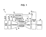
- FIG. 1 is a schematic diagram of a gas turbine engine system 10 including a compressor 12, a combustor 14, and a turbine 16 coupled by a drive shaft 15 to the compressor 12.
- the system 10 can have a single combustor or a plurality of combustors (two shown in the figure).
- the combustors are DLN combustors.
- the combustors are lean premixed combustors.
- the gas turbine engine is managed by a combination of operator commands and a control system 18.
- An inlet duct system 20 channels ambient air to the compressor inlet guide vanes 21 which, by modulation with actuator 25, regulates the amount of air to compressor 12.
- An exhaust system 22 channels combustion gases from the outlet of turbine 16 through, for example, sound absorbing, heat recovery and possibly emissions control devices.
- Turbine 16 may drive a generator 24 that produces electrical power or any other type of mechanical load.
- sensors 26 may monitor ambient temperature, pressure and humidity surrounding gas turbine engine system 10, compressor discharge pressure and temperature, turbine exhaust gas temperature and emissions, and other pressure and temperature measurements within the gas turbine engine.
- Sensors 26 may also comprise flow sensors, speed sensors, flame detector sensors, valve position sensors, guide vane angle sensors, dynamic pressure sensors, and other sensors that sense various parameters relative to the operation of gas turbine engine system 10.
- “parameters” refer to physical properties whose values can be used to define the operating conditions of gas turbine engine system 10, such as temperatures, pressures, fluid flows at defined locations, and the like.
- sensors 26 there may be one or more sensors to monitor, measure or infer fuel properties sufficiently to determine the fuel composition prior to and/or after the non-catalytic fuel reformer 32 described below.
- the sensors may sense one or more of the following: fractional (fuel) composition, hydrogen content, carbon monoxide content, a parameter representative of the fuel MWI, fuel temperature, fuel and oxidant flow rates, products temperature, and the like.
- a fuel controller 28 responds to commands from the control system 18 to continuously regulate the fuel flowing from a fuel supply to the combustor(s) 14, and the fuel splits (independently controlled fuel supply to fuel circuits) to multiple fuel nozzle injectors (i.e., fuel circuits) located within each of the combustor(s) 14.
- Fuel control system 28 may also be directed by the controller 18 to select the type of fuel or a mix of fuels for the combustor if more than one fuel is available.
- the control system 18 may be a computer system having a processor(s) that executes programs to control the operation of the gas turbine using the sensor inputs described above and instructions from additional operators.
- the programs executed by the control system 18 may include scheduling algorithms for regulating fuel flow, fuel reforming, and fuel splits to combustor(s) 14. More specifically, the commands generated by the control system cause actuators in the fuel controller 28 to regulate the flow to both the non-catalytic fuel reformer 32 and the fuel nozzle injectors, adjust inlet guide vanes 21 on the compressor, regulate the flow of an oxidant source to the non-catalytic fuel reformer 32, or control other system settings on the gas turbine.
- the algorithms thus enable control system 18 to maintain the combustor firing temperature and exhaust temperature to within predefined temperature limits and to maintain the turbine exhaust NOx and CO emissions to below predefined limits at part-load through full load gas turbine operating conditions.
- the combustors 14 may be a DLN combustion system, and the control system 18 may be programmed and modified to control the fuel splits for the DLN combustion system according to the predetermined fuel split schedules, modified by a tuning process which occurs after every major combustor and gas turbine maintenance outages to improve emissions and combustion dynamics.
- Combustor fuel splits are also set by the periodic tuning process to satisfy performance objectives while complying with operability boundaries of the gas turbine. All such control functions have a goal to improve operability, reliability, and availability of the gas turbine.
- the non-catalytic fuel reformer 32 is in fluid communication with the fuel flow of one or more fuel circuits (not shown) in the fuel control system 28. Again, the non-catalytic fuel reformer 32 is configured to partially reform a portion of the fuel fed to the gas turbine to increase fuel reactivity.
- the non-catalytic fuel reformer as described herein is configured to pre-bum (i.e., partially oxidize) a portion of the fuel stream feeding the gas turbine.
- the non-catalytic fuel reformer is fed a mixture of oxidant and fuel, wherein the fuel and oxidant is premixed and then burned in the non-catalytic fuel reformer.
- the oxidant can be supplied to the non-catalytic fuel reformer by the compressor 12 or it may be provided by a separate oxidant supply.
- Exemplary oxidants to be provided to the non-catalytic fuel reformer can include, without limitation, pure oxygen, air, oxygen-enriched air, combinations thereof, and the like.
- the fuel and oxidant are premixed to a ratio that is fuel-rich, oxygen-depleted.
- An exemplary mixture ratio of oxygen-to-fuel will be sufficiently reactive to support a conventional flame in the non-catalytic fuel reformer without the flame temperature being so high as to generate appreciable concentrations of NOx.
- the range of acceptable mixture ratios in the non-catalytic fuel reformer therefore, is fairly narrow between these two limits and will depend in large part on the composition of the fuel entering the reformer.
- the mass ratio of oxygen-to-fuel is generally in the range of about 1.5:1 to about 4:1, and more specifically about 2.3:1, where the fuel is methane.
- the mass ratio of air-to-fuel is 10: 1.
- a fuel-rich, oxygen-depleted premixed mixture in the non-catalytic fuel reformer when combusted produces carbon dioxide, carbon monoxide, hydrogen, and water from the methane.
- nitrogen is generally present in the combustion products as an inert gas that passes through the reaction. The reformate is then blended back in with the balance of the fuel stream
- the mass ratio of air-to-fuel is generally between about 20:1 to 5:1; specifically about 18:1 to 10:1; and more specifically about 17:1.
- Such a near-stoichiometric fuel-air mixture will result in reformate containing predominantly H 2 O, CO 2 , and N 2 , with very small amounts of H 2 and CO.
- the resulting mixture will be sufficiently oxygen-depleted that it is no longer flammable, and carries no risk of further combustion when blended back into the fuel stream.
- the objective of this embodiment is MWI control alone.
- the amount of the fuel reformed in the non-catalytic fuel reformer 32 can be adjusted to control the fuel MWI within predetermined limits to compensate for incoming fuel composition variation. Control of the proportion of fuel diverted to the non-catalytic fuel reformer is a means of controlling the Wobbe Index of the resultant mixed fuel stream.
- the MWI is reduced to its predetermined target value by a combination of the inclusion of inert species (e.g., nitrogen, water) in the mixed fuel stream and the exothermic nature of the reaction.
- inert species e.g., nitrogen, water
- premixed combustion systems provides a system that is more tolerant to MWI variation in the fuel stream than current lean combustion systems without such a reformer.
- the hydrogen and carbon monoxide present in the reformate provide reactive species that extend lean limits of the gas turbine combustor.
- the increased fuel reactivity allows the combustor to be turned down further without going out of CO emissions limits.
- the increased chemical reactivity of the fuel can also help to greatly reduce the formation of NOx in the combustor, because a more reactive fuel does not require the fuel nozzle(s) to be run at such a high flame temperature. Therefore, as mentioned previously, reducing the maximum flame temperature of the fuel nozzle(s) will greatly reduce the formation of NOx in the combustor.
- the non-catalytic fuel reformer 32 can be used to partially reform any fuel typically used in gas turbine engine combustion systems, such as natural gas (methane) and other like gaseous-phase fuels.
- the non-catalytic fuel reformer 32 is configured to partially oxidize a small percentage of the fuel to form hydrogen, carbon monoxide, and other combustion products.
- the non-catalytic fuel reformer can reform about 0.1 1 volume percent (vol%) to about 100 vol% of the fuel, specifically about 0.5 vol% to about 50 vol%, more specifically about 0.8 vol% to about 5 vol%, and even more specifically about 1 vol% to about 2 vol%.
- the desired percentage of fuel reformed can depend on a number of factors such as, without limitation, turbine load, fuel type, water and/or oxidant additives, fuel temperature, emissions, and the like.
- the control system 18 can be configured to regulate fuel flow to the non-catalytic fuel reformer 32 and control the percentage of fuel reformed based on feedback from any of the sensors 26.
- the non-catalytic fuel reformer can be disposed in any location in fluid communication with the fuel system of the gas turbine combustion system wherein the non-catalytic fuel reformer can receive at least a portion of the fuel.
- the non-catalytic fuel reformer system can be in fluid communication with one fuel circuit of the combustor or a plurality of the fuel circuits.
- a gas turbine combustion system can comprise a single non-catalytic fuel reformer or a plurality of non-catalytic fuel reformers in fluid communication with one or more of the fuel circuits.
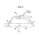
- FIG. 2 illustrates an exemplary embodiment of a non-catalytic fuel reformer 100 in fluid communication with a fuel circuit 102.
- the non-catalytic fuel reformer 100 is disposed outside the fuel conduit 104 such that a portion of the fuel flowing through the conduit must be diverted to pass through the reformer. A portion of the fuel can be diverted into the non-catalytic fuel reformer 100 through the operation of a valve system.
- a throttle valve 106 is shown disposed the fuel conduit 104.
- the throttle valve 106 is disposed downstream of the inlet 108 to the fuel reformer bypass 110 and upstream of the outlet 112 from the fuel reformer bypass 110.
- the throttle valve 106 is configured to controllably divert a portion of the fuel from the fuel conduit 104 to the fuel reformer bypass 110 by creating a pressure drop across the non-catalytic fuel reformer 100.
- by-pass valves can be disposed at the inlet 108 and/or outlet 112 locations of the fuel reformer bypass 110 to actively control fuel flow thereto.
- the throttle valve 106 (and/or by-pass valves), as well as the non-catalytic fuel reformer 100, can be in operative communication with an engine control system to provide on-demand reformation of a specific portion of the turbine fuel.
- the non-catalytic fuel reformer 100 can be isolated from the fuel circuit 102 and serviced without interruption of the fuel flow to the gas turbine combustor.
- An oxidant inlet 114 is in fluid communication with the non-catalytic fuel reformer 100 and is configured to provide oxygen for premixing with the fuel before combustion in the fuel reformer.
- the oxidant inlet 114 can be in fluid communication with the compressor of the gas turbine or it can be in fluid communication with a separate oxidant supply. Again, the oxidant inlet 114 can supply oxygen, air, oxygen-enriched air, or combinations thereof to the non-catalytic fuel reformer 100.
- the non-catalytic fuel reformer described herein is in operative communication with an engine control system configured to provide control of the fraction of the fuel reformed, and therefore, control of the MWI of the mixed fuel stream fed to the gas turbine combustor.
- the control system can monitor feedback from sensors, thermocouples, and the like that can detect, among other things, the fuel fraction diverted to the non-catalytic fuel reformer and the MWI of the incoming fuel stream.
- the control system further monitors process conditions, such as temperatures and pressures, throughout the gas turbine engine combustion system.
- Such a control system can be employed to adjust fuel feed rates, fuel pressures, valve operation of the fuel reformer bypass, adjust supplementary process gas feed rates (e.g., feed rate from the oxidant inlet), or control other like conditions within the gas turbine system.
- a fuel gas analysis subsystem can further be included to provide additional feedback to such a control system.
- the control system can operate and control the fuel reformer based on any number of process parameters. Feedback from sensors, thermocouples, and the like also alert the control system to various other conditions within the gas turbine system.
- Exemplary process parameters can include, without limitation, temperature (e.g., ambient temperature, fuel temperature, nozzle temperature, combustor temperature, and the like), humidity, inlet pressure loss, dynamic pressure, exhaust backpressure, exhaust emissions (e.g., NOx, CO, UHC, and the like), turbine load/power, a parameter representative of fuel MWI, and the like.
- This feedback loop between the parameters monitoring and the control system can indicate the need to alter the MWI of the mixed fuel stream or the reactivity of the fuel, and therefore, change the mixture ratio within the non-catalytic fuel reformer by changing one or both of the fuel flow and oxidant flow thereto.
- certain parameters reach a predetermined target, it may be suitable to alter the portion of the fuel being reformed or even momentarily cease reforming altogether.
- the non-catalytic fuel reformer and method of its use in a gas turbine engine combustion system as described herein can advantageously reform a portion of fuel in one or more fuel circuits to control the MWI of the fuel feeding the turbine combustor despite variation of MWI in the incoming fuel stream.
- the non-catalytic fuel reformer is further configured to increase the fuel reactivity.
- the fuel reformer system is in operative communication with an active feed back control system to provide fuel conditioning as required to control the MWI to fixed set points for the fuel entering the gas turbine and achieve desired emissions (e.g., NOx, CO, yellow plume, turn down, and the like).
- the non-catalytic fuel reformer can permit current gas turbines with current low-emissions combustions systems to be used in markets where fuel variability normally precludes the application of lean, premixed combustion systems, or at least greatly reduces their low-emissions effectiveness due to dynamic combustion instability. Moreover, greater load turndown can be achieved by the gas turbines due to the extension of lean limits by the doping of hydrogen and carbon monoxide in the fuel via the non-catalytic fuel reformer. Further, the non-catalytic fuel reformer as described herein does not require a catalyst and does not promote a catalytic reaction therein. There is no concern, therefore, with the catalyst becoming poisoned or requiring regularly scheduled recharging that causes reformer downtime.
- Ranges disclosed herein are inclusive and combinable (e.g., ranges of "up to about 25 vol%, or, more specifically, about 5 vol% to about 20 vol%", is inclusive of the endpoints and all intermediate values of the ranges of "about 5 vol% to about 25 vol%,” etc.).
- “Combination” is inclusive of blends, mixtures, alloys, reaction products, and the like.
- the terms “first,” “second,” and the like, herein do not denote any order, quantity, or importance, but rather are used to distinguish one element from another, and the terms “a” and “an” herein do not denote a limitation of quantity, but rather denote the presence of at least one of the referenced item.
- the modifier “about” used in connection with a quantity is inclusive of the stated value and has the meaning dictated by context, (e.g., includes the degree of error associated with measurement of the particular quantity).
- the suffix "(s)” as used herein is intended to include both the singular and the plural of the term that it modifies, thereby including one or more of that term (e.g., the colorant(s) includes one or more colorants).
Landscapes
- Engineering & Computer Science (AREA)
- Chemical & Material Sciences (AREA)
- Combustion & Propulsion (AREA)
- Mechanical Engineering (AREA)
- General Engineering & Computer Science (AREA)
- Hydrogen, Water And Hydrids (AREA)
Applications Claiming Priority (1)
| Application Number | Priority Date | Filing Date | Title |
|---|---|---|---|
| US12/792,037 US20110296844A1 (en) | 2010-06-02 | 2010-06-02 | Gas turbine combustion system with rich premixed fuel reforming and methods of use thereof |
Publications (1)
| Publication Number | Publication Date |
|---|---|
| EP2392797A2 true EP2392797A2 (de) | 2011-12-07 |
Family
ID=44118094
Family Applications (1)
| Application Number | Title | Priority Date | Filing Date |
|---|---|---|---|
| EP11168318A Withdrawn EP2392797A2 (de) | 2010-06-02 | 2011-05-31 | Gasturbinenbrennkammersystem mit Reformierung von fettem Vormischbrennstoff und Verwendungsverfahren dafür |
Country Status (4)
| Country | Link |
|---|---|
| US (1) | US20110296844A1 (de) |
| EP (1) | EP2392797A2 (de) |
| JP (1) | JP2011252494A (de) |
| CN (1) | CN102269061A (de) |
Cited By (1)
| Publication number | Priority date | Publication date | Assignee | Title |
|---|---|---|---|---|
| US9791351B2 (en) | 2015-02-06 | 2017-10-17 | General Electric Company | Gas turbine combustion profile monitoring |
Families Citing this family (21)
| Publication number | Priority date | Publication date | Assignee | Title |
|---|---|---|---|---|
| US20130074515A1 (en) * | 2011-09-23 | 2013-03-28 | General Electric Company | Gas turbine engine system and method of providing a fuel supplied to one or more combustors in a gas turbine engine system |
| US20130192249A1 (en) * | 2012-01-26 | 2013-08-01 | General Electric Company | Gas Turbine Engine System and Method for Controlling a Temperature of a Conduit in a Gas Turbine Engine System |
| KR101915196B1 (ko) * | 2012-05-18 | 2018-11-05 | 한화에어로스페이스 주식회사 | 가스터빈 시스템 |
| US9435690B2 (en) * | 2012-06-05 | 2016-09-06 | General Electric Company | Ultra-violet flame detector with high temperature remote sensing element |
| US10392959B2 (en) | 2012-06-05 | 2019-08-27 | General Electric Company | High temperature flame sensor |
| ITMI20130089A1 (it) * | 2013-01-23 | 2014-07-24 | Ansaldo Energia Spa | Impianto a turbina a gas per la produzione di energia elettrica e metodo per operare detto impianto |
| EP2770182B1 (de) | 2013-02-25 | 2015-10-14 | Alstom Technology Ltd | Verfahren zur Anpassung der Temperatur von Erdgas für eine Kraftstoffversorgungsleitung einer Gasturbine sowie Gasturbine |
| US9790834B2 (en) | 2014-03-20 | 2017-10-17 | General Electric Company | Method of monitoring for combustion anomalies in a gas turbomachine and a gas turbomachine including a combustion anomaly detection system |
| US9773584B2 (en) | 2014-11-24 | 2017-09-26 | General Electric Company | Triaxial mineral insulated cable in flame sensing applications |
| EP3056814A1 (de) * | 2015-02-13 | 2016-08-17 | General Electric Technology GmbH | Verfahren zur steuerung der kraftstoffverteilung zwischen verschiedenen stufen einer gasturbinenbrennkammer |
| US20170051682A1 (en) * | 2015-08-20 | 2017-02-23 | General Electric Company | System and method for abatement of dynamic property changes with proactive diagnostics and conditioning |
| US10260460B2 (en) | 2015-11-20 | 2019-04-16 | Caterpillar Inc. | Feedback control of fuel reformer-engine system |
| JP6552976B2 (ja) * | 2016-02-01 | 2019-07-31 | 三菱重工業株式会社 | バーナ、これを備えたボイラ及びこれを備えた船舶 |
| US9976522B2 (en) | 2016-04-15 | 2018-05-22 | Solar Turbines Incorporated | Fuel injector for combustion engine and staged fuel delivery method |
| US10234142B2 (en) | 2016-04-15 | 2019-03-19 | Solar Turbines Incorporated | Fuel delivery methods in combustion engine using wide range of gaseous fuels |
| US10247155B2 (en) | 2016-04-15 | 2019-04-02 | Solar Turbines Incorporated | Fuel injector and fuel system for combustion engine |
| JP6477638B2 (ja) * | 2016-09-14 | 2019-03-06 | トヨタ自動車株式会社 | 熱、水素生成装置 |
| AU2018229961B2 (en) * | 2017-03-07 | 2023-11-02 | 8 Rivers Capital, Llc | System and method for operation of a flexible fuel combustor for a gas turbine |
| KR102789952B1 (ko) | 2021-01-08 | 2025-04-01 | 미츠비시 파워 가부시키가이샤 | 가스 터빈 연소기 및 가스 터빈 |
| US12065978B2 (en) * | 2022-11-01 | 2024-08-20 | Pratt & Whitney Canada Corp. | Compressor boost control for aircraft engine |
| CN117130411A (zh) * | 2023-08-15 | 2023-11-28 | 国家电投集团北京重燃能源科技发展有限公司 | 掺氢燃料气的温度控制方法、装置、电子设备及存储介质 |
Family Cites Families (12)
| Publication number | Priority date | Publication date | Assignee | Title |
|---|---|---|---|---|
| US2125714A (en) * | 1935-10-26 | 1938-08-02 | Standard Oil Dev Co | Naphtha reforming |
| US2917449A (en) * | 1955-01-25 | 1959-12-15 | Texaco Inc | Method of upgrading a petroleum naphtha |
| US5048284A (en) * | 1986-05-27 | 1991-09-17 | Imperial Chemical Industries Plc | Method of operating gas turbines with reformed fuel |
| DE3618982A1 (de) * | 1986-06-05 | 1987-12-10 | Bosch Gmbh Robert | Stelleinrichtung fuer eine drosselklappe |
| US6432368B1 (en) * | 1994-06-30 | 2002-08-13 | General Electric Company | Staged catalytic ammonia decomposition in integrated gasification combined cycle systems |
| US20020020113A1 (en) * | 1997-12-01 | 2002-02-21 | The Board Of Trustees Of The University Of | Superadiabatic generation of hydrogen and hydrocarbons |
| AU2001269854B2 (en) * | 2000-06-13 | 2005-08-18 | Conocophillips Company | Supported nickel-magnesium oxide catalysts and processes for the production of syngas |
| US6783354B2 (en) * | 2002-05-20 | 2004-08-31 | Catacel Corporation | Low NOX combustor for a gas turbine |
| US7966830B2 (en) * | 2006-06-29 | 2011-06-28 | The Boeing Company | Fuel cell/combustor systems and methods for aircraft and other applications |
| US20080296018A1 (en) * | 2007-05-29 | 2008-12-04 | Zubrin Robert M | System and method for extracting petroleum and generating electricity using natural gas or local petroleum |
| US7980082B2 (en) * | 2007-08-01 | 2011-07-19 | General Electric Company | Wobbe control and enhanced operability through in-line fuel reforming |
| US20110142722A1 (en) * | 2009-12-14 | 2011-06-16 | John William Hemmings | Method and apparatus for producing synthesis gas |
-
2010
- 2010-06-02 US US12/792,037 patent/US20110296844A1/en not_active Abandoned
-
2011
- 2011-05-30 JP JP2011119829A patent/JP2011252494A/ja not_active Withdrawn
- 2011-05-31 EP EP11168318A patent/EP2392797A2/de not_active Withdrawn
- 2011-06-02 CN CN2011101572540A patent/CN102269061A/zh active Pending
Non-Patent Citations (1)
| Title |
|---|
| None |
Cited By (1)
| Publication number | Priority date | Publication date | Assignee | Title |
|---|---|---|---|---|
| US9791351B2 (en) | 2015-02-06 | 2017-10-17 | General Electric Company | Gas turbine combustion profile monitoring |
Also Published As
| Publication number | Publication date |
|---|---|
| CN102269061A (zh) | 2011-12-07 |
| US20110296844A1 (en) | 2011-12-08 |
| JP2011252494A (ja) | 2011-12-15 |
Similar Documents
| Publication | Publication Date | Title |
|---|---|---|
| EP2392797A2 (de) | Gasturbinenbrennkammersystem mit Reformierung von fettem Vormischbrennstoff und Verwendungsverfahren dafür | |
| EP2573359A2 (de) | Gasturbinenantriebssystem und Verfahren zum Bereitstellen eines Kraftstoffes, der an einen oder mehrerer Brennkammern in einem Gasturbinenantriebssystem geliefert wird | |
| US7980082B2 (en) | Wobbe control and enhanced operability through in-line fuel reforming | |
| AU2009303735B2 (en) | Methods and systems for controlling the products of combustion | |
| US20100300110A1 (en) | Gas Turbine Combustion System With In-Line Fuel Reforming And Methods Of Use Thereof | |
| CN101793196B (zh) | 用于燃气涡轮的自动化燃料混合和控制的系统和方法 | |
| EP2581561B1 (de) | Betriebsverfahren für Wasserstoff-/Erdgasgemische innerhalb einer Wiedererhitzungsgasturbine und Gasturbine | |
| US9500127B2 (en) | Power plant and method for its operation | |
| TW202328560A (zh) | 用於控制燃氣渦輪之燃料摻合物的系統及方法 | |
| JP2014070636A (ja) | Co2の排出を管理するための方法およびシステム | |
| EP2620621A2 (de) | Gasturbinenmotorsystem und Verfahren zur Regelung der Temperatur einer Leitung in einem Gasturbinenmotorsystem | |
| WO2023138897A1 (en) | Gas turbine system with diffusion-flame combustion and fuel blending for reducing undesired emissions |
Legal Events
| Date | Code | Title | Description |
|---|---|---|---|
| AK | Designated contracting states |
Kind code of ref document: A2 Designated state(s): AL AT BE BG CH CY CZ DE DK EE ES FI FR GB GR HR HU IE IS IT LI LT LU LV MC MK MT NL NO PL PT RO RS SE SI SK SM TR |
|
| AX | Request for extension of the european patent |
Extension state: BA ME |
|
| PUAI | Public reference made under article 153(3) epc to a published international application that has entered the european phase |
Free format text: ORIGINAL CODE: 0009012 |
|
| STAA | Information on the status of an ep patent application or granted ep patent |
Free format text: STATUS: THE APPLICATION IS DEEMED TO BE WITHDRAWN |
|
| 18D | Application deemed to be withdrawn |
Effective date: 20141202 |