EP2581561B1 - Betriebsverfahren für Wasserstoff-/Erdgasgemische innerhalb einer Wiedererhitzungsgasturbine und Gasturbine - Google Patents
Betriebsverfahren für Wasserstoff-/Erdgasgemische innerhalb einer Wiedererhitzungsgasturbine und Gasturbine Download PDFInfo
- Publication number
- EP2581561B1 EP2581561B1 EP12188148.6A EP12188148A EP2581561B1 EP 2581561 B1 EP2581561 B1 EP 2581561B1 EP 12188148 A EP12188148 A EP 12188148A EP 2581561 B1 EP2581561 B1 EP 2581561B1
- Authority
- EP
- European Patent Office
- Prior art keywords
- fuel
- hydrogen
- combustor
- turbine
- gas turbine
- Prior art date
- Legal status (The legal status is an assumption and is not a legal conclusion. Google has not performed a legal analysis and makes no representation as to the accuracy of the status listed.)
- Active
Links
- 229910052739 hydrogen Inorganic materials 0.000 title claims description 95
- 239000001257 hydrogen Substances 0.000 title claims description 95
- UFHFLCQGNIYNRP-UHFFFAOYSA-N Hydrogen Chemical compound [H][H] UFHFLCQGNIYNRP-UHFFFAOYSA-N 0.000 title claims description 90
- 239000000203 mixture Substances 0.000 title claims description 40
- 239000007789 gas Substances 0.000 title claims description 31
- VNWKTOKETHGBQD-UHFFFAOYSA-N methane Chemical compound C VNWKTOKETHGBQD-UHFFFAOYSA-N 0.000 title description 40
- 239000003345 natural gas Substances 0.000 title description 20
- 238000011017 operating method Methods 0.000 title description 3
- 239000000446 fuel Substances 0.000 claims description 91
- 238000002156 mixing Methods 0.000 claims description 15
- 238000000034 method Methods 0.000 claims description 11
- 238000011144 upstream manufacturing Methods 0.000 claims description 2
- 230000001105 regulatory effect Effects 0.000 claims 2
- 238000002485 combustion reaction Methods 0.000 description 14
- 230000009257 reactivity Effects 0.000 description 8
- 230000009467 reduction Effects 0.000 description 6
- 150000002431 hydrogen Chemical class 0.000 description 5
- 230000006641 stabilisation Effects 0.000 description 5
- 238000011105 stabilization Methods 0.000 description 5
- OKTJSMMVPCPJKN-UHFFFAOYSA-N Carbon Chemical compound [C] OKTJSMMVPCPJKN-UHFFFAOYSA-N 0.000 description 3
- 238000013459 approach Methods 0.000 description 3
- 229910052799 carbon Inorganic materials 0.000 description 3
- 239000002737 fuel gas Substances 0.000 description 3
- 230000006872 improvement Effects 0.000 description 3
- 230000008569 process Effects 0.000 description 3
- 239000000376 reactant Substances 0.000 description 3
- UGFAIRIUMAVXCW-UHFFFAOYSA-N Carbon monoxide Chemical compound [O+]#[C-] UGFAIRIUMAVXCW-UHFFFAOYSA-N 0.000 description 2
- 230000003247 decreasing effect Effects 0.000 description 2
- 238000013461 design Methods 0.000 description 2
- 238000010586 diagram Methods 0.000 description 2
- 230000005611 electricity Effects 0.000 description 2
- 238000004519 manufacturing process Methods 0.000 description 2
- 230000007246 mechanism Effects 0.000 description 2
- 230000000116 mitigating effect Effects 0.000 description 2
- 239000007800 oxidant agent Substances 0.000 description 2
- 230000001590 oxidative effect Effects 0.000 description 2
- 230000000087 stabilizing effect Effects 0.000 description 2
- 230000003466 anti-cipated effect Effects 0.000 description 1
- 239000012620 biological material Substances 0.000 description 1
- 230000015572 biosynthetic process Effects 0.000 description 1
- 229910002091 carbon monoxide Inorganic materials 0.000 description 1
- 238000006243 chemical reaction Methods 0.000 description 1
- 230000007423 decrease Effects 0.000 description 1
- 230000000694 effects Effects 0.000 description 1
- 238000005868 electrolysis reaction Methods 0.000 description 1
- 230000007613 environmental effect Effects 0.000 description 1
- 239000003546 flue gas Substances 0.000 description 1
- 238000002309 gasification Methods 0.000 description 1
- 238000002347 injection Methods 0.000 description 1
- 239000007924 injection Substances 0.000 description 1
- 238000011835 investigation Methods 0.000 description 1
- 238000012986 modification Methods 0.000 description 1
- 230000004048 modification Effects 0.000 description 1
- 238000012544 monitoring process Methods 0.000 description 1
- 230000007935 neutral effect Effects 0.000 description 1
- 230000003647 oxidation Effects 0.000 description 1
- 238000007254 oxidation reaction Methods 0.000 description 1
- 230000001902 propagating effect Effects 0.000 description 1
- 230000002269 spontaneous effect Effects 0.000 description 1
- 230000002459 sustained effect Effects 0.000 description 1
Images


Classifications
-
- F—MECHANICAL ENGINEERING; LIGHTING; HEATING; WEAPONS; BLASTING
- F01—MACHINES OR ENGINES IN GENERAL; ENGINE PLANTS IN GENERAL; STEAM ENGINES
- F01D—NON-POSITIVE DISPLACEMENT MACHINES OR ENGINES, e.g. STEAM TURBINES
- F01D19/00—Starting of machines or engines; Regulating, controlling, or safety means in connection therewith
-
- F—MECHANICAL ENGINEERING; LIGHTING; HEATING; WEAPONS; BLASTING
- F02—COMBUSTION ENGINES; HOT-GAS OR COMBUSTION-PRODUCT ENGINE PLANTS
- F02C—GAS-TURBINE PLANTS; AIR INTAKES FOR JET-PROPULSION PLANTS; CONTROLLING FUEL SUPPLY IN AIR-BREATHING JET-PROPULSION PLANTS
- F02C3/00—Gas-turbine plants characterised by the use of combustion products as the working fluid
- F02C3/20—Gas-turbine plants characterised by the use of combustion products as the working fluid using a special fuel, oxidant, or dilution fluid to generate the combustion products
-
- F—MECHANICAL ENGINEERING; LIGHTING; HEATING; WEAPONS; BLASTING
- F02—COMBUSTION ENGINES; HOT-GAS OR COMBUSTION-PRODUCT ENGINE PLANTS
- F02C—GAS-TURBINE PLANTS; AIR INTAKES FOR JET-PROPULSION PLANTS; CONTROLLING FUEL SUPPLY IN AIR-BREATHING JET-PROPULSION PLANTS
- F02C9/00—Controlling gas-turbine plants; Controlling fuel supply in air- breathing jet-propulsion plants
- F02C9/26—Control of fuel supply
- F02C9/32—Control of fuel supply characterised by throttling of fuel
- F02C9/34—Joint control of separate flows to main and auxiliary burners
-
- F—MECHANICAL ENGINEERING; LIGHTING; HEATING; WEAPONS; BLASTING
- F02—COMBUSTION ENGINES; HOT-GAS OR COMBUSTION-PRODUCT ENGINE PLANTS
- F02C—GAS-TURBINE PLANTS; AIR INTAKES FOR JET-PROPULSION PLANTS; CONTROLLING FUEL SUPPLY IN AIR-BREATHING JET-PROPULSION PLANTS
- F02C9/00—Controlling gas-turbine plants; Controlling fuel supply in air- breathing jet-propulsion plants
- F02C9/26—Control of fuel supply
- F02C9/40—Control of fuel supply specially adapted to the use of a special fuel or a plurality of fuels
Definitions
- the present invention relates to the field of combustion technology for gas turbines.
- the aerodynamic stabilization used in the first combustor means the stability of this combustor can be influenced by changes in the burning velocity, which is strongly influenced by the fuel consumption and operating conditions.
- the auto-ignition delay time, the stabilizing factor in the reheat burner is also influenced by these parameters but as the axial location of the flame can alter within the combustor with limited impact on performance the potential exists to design a reheat combustion system that can tolerate a range of' fuel compositions.
- a gas turbine is operated using a varying blend of a first fuel, preferably natural gas, and a second fuel comprising hydrogen.
- the hydrogen concentration is varied depending on operating conditions in order to reduce emissions of CO and NOx, and/or to mitigate LBO.
- the fuel mixture is varied using a controller based on a combination of factors in a modular operation concept to address different issues according to relevant load limitations.
- a method of operating a gas turbine according to this modular operational concept is also provided.
- a multi-stage gas turbine operating with a reheat cycle is used to burn a varying blend of natural gas and hydrogen, depending on the availability of hydrogen and the operating conditions.
- Different concentrations of hydrogen can be utilized in the two combustion systems.
- the fuel used in the second combustor is enriched with the required concentration of hydrogen, with the appropriate flame position being achieved by adjusting the inlet temperature to the second combustor to improve LBO.
- the stability range can be increased by the addition of a controlled amount of hydrogen to the fuel. Additionally, NOx and CO emissions can be reduced.
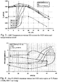
- up to 20% hydrogen is added to the natural gas fuel for reduced NOx emission at baseload conditions.
- the NOx reduction appears to be due to improvement in the mixing quality due to increased turbulence and diffusivity caused by the addition of hydrogen.
- up to 20% hydrogen is added to the natural gas fuel to reduce CO emissions at partial load conditions. This appears to be due to more reactivity of the fuel air mixture as well as possibly more OH radicals being generated for CO oxidation.
- addition of 30% or more hydrogen is added to the natural gas fuel to improve LBO.
- the hydrogen can be added based on a combination of the above-noted factors in a modular operation concept to address different issues according to relevant load limitations. For example, higher hydrogen can be used at idle for LBO mitigation; intermediate hydrogen addition can be used at partial load conditions for CO and NOx emission reduction; and low hydrogen addition in combination with a decreased S1 R (Stage 1 Ratio) can be utilized at baseload for low NOx emissions.
- S1 R Stage 1 Ratio
- the disclosure deals with current and future capability to burn hydrogen enriched natural gas as a means of utilizing excess renewable generating capacity during off-peak periods. It relates to an operating method for the operation of an industrial gas turbine with a hydrogen enriched natural gas fuel and/or a diluted hydrogen fuel.
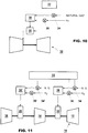
- Fig. 1 shows a reheat gas turbine 10 with a compressor 12, high pressure and low pressure output turbine blade sections 14, 16, and first and second annular combustors 18, 20.
- Fuel is injected into the combustors 18, 20 with fuel lances 22, 24, for the respective chambers 18, 20.
- the fuel is preferably a controlled mix of natural gas and hydrogen.
- the fuel is blended in fuel blending systems 30, 30', preferably mixing chambers, associated with each turbine stage in which varying amounts of natural gas and hydrogen are mixed depending on operating conditions and/or the availability of hydrogen required for one or both combustors 18, 20.
- the mixture is controlled by a controller 32, which can be a programmable logic controller (pic) or computer based controller that controls servo valves 34, 34' for natural gas for each turbine stage and servo valves 36, 36' for hydrogen.
- the fuel is fed to either or both of the combustors 18, 20, shown in Figs. 1 and 11 .
- Burners 26 are provided to ignite the fuel/compressed air mixture in the first annular combustor 18, while the second (reheat) combustor 20 receives hot gases from the first combustor 18 at a high enough temperature to auto-ignite the additional fuel.
- Separate fuel blending systems 30, 30' allow the combustors 18, 20 to receive different blends.
- the operating method for a turbine 10 provides different stabilization mechanisms utilized within the two stage combustion system of a reheat gas turbine 10, flexibility inherent in a reheat turbine as to which point in the operating cycle the reheat burner operates, and hydrogen to increase fuel reactivity, and hence burner stability, when operating the reheat combustor 20 at low inlet temperatures or part load.
- the temperature set point defined in the control program is adjusted in real time to accommodate changes in the reactivity of the fuel (driven by fuel composition changes). Such changes would be handled automatically by the controller 32 by using suitable operating maps defining an appropriate inlet temperature for a given composition.
- the fuel composition can be identified either by real time monitoring of a time varying fuel with an instrument such as a gas chromatograph. Alternatively where the fuel is blended from two or more sources the output from flow meters in the individual streams may be monitored to determine the composition at inlet to the burner.
- flame stabilization is achieved by introducing complex aerodynamic structures that balance the speed at which the flame front attempts to propagate into the premixed reactants. For this reason it is possible to cause the flame to stabilize in free space.
- the speed at which the flame propagates is a function, among other parameters, of the composition of the reactants, and in particular the fuel type and oxidant concentration. It is thus possible to produce an operating point (whether by the choice of fuel, or by limiting the oxidant availability (e.g. flue gas recirculation), or by alternative means) where a significant imbalance exists between the velocity in the flow field and the propagation speed of the flame, such that the flame velocity is lower than the flow velocity. In this situation the flame will cease to be stable and be extinguished.
- the controller 32 allows such flame instabilities to be avoided by adding an appropriate concentration of hydrogen to the fuel.
- hydrogen is added to the fuel flow to restore stability. It is further provided that the amount of hydrogen to be added can be identified automatically by an engine control algorithm based on suitable maps identifying the required hydrogen to stabilize the operating point.
- the gas turbine 10 can be started on natural gas using the first stage combustor 18.
- the engine would run up to an operating point (approximately 6 to 8 bar) at which the increased reactivity of hydrogen at lower pressures is no longer apparent prior to the starting of the reheat combustion system.
- the proportion of hydrogen in the fuel for the reheat combustor 20 is selected automatically by the controller 32.
- a wide range of differing hydrogen compositions can be accommodated by automatically applying a map of reheat burner inlet temperature against hydrogen composition, i.e. if a high hydrogen concentration is required this can be accommodated by de-rating the inlet temperature.
- the controller 32 adding a small proportion of hydrogen, again based on an automatic operational map, to the primary combustor 18 to increase reactivity and hence extend the proportion of hydrogen that can be accommodated.
- the controller 32 can also be used to lower CO emissions by the addition of hydrogen preferably in the 20% to 40% range, as shown in Figs. 6 and 7 . This is believed to be due to increased fuel reactivity and OH radical formation. This effect is important at high pressures.
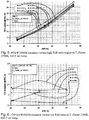
- Figs. 8 and 9 show that pressure drop (zeta) is stable for hydrogen up to about 20%. Above 20% a modest increase in zeta is observed.
- the controller 32 can operate to optimize certain performance characteristics depending on operating conditions. Hydrogen is preferably added to the fuel mixture to about 20% for the baseload condition to reduce emissions of NOx and CO. At part load conditions, 20% hydrogen is added to the fuel mixture to continue to reduce CO emissions. 30% or more hydrogen can be added to the fuel mix to improve LBO conditions, with some sacrifice in other areas. As previously noted, the addition of the hydrogen to the fuel mix can be used in both single or reheat combustors. For reheat combustors 20, the hydrogen addition to the fuel mix can be controlled separately for the first and second stage combustors 18, 20.
- the controller 32 preferably utilizes a modular operation concept so that the controlled addition of hydrogen is done at different times to address different issues, with higher hydrogen (30% or more) addition at idle for LBO mitigation, intermediate hydrogen addition (10% to 30%) at part load to reduce CO and NOx emissions, and low hydrogen addition and a decreased S1 R at baseload for low NOx.
- This fuel modulation generally does not affect pressure drop, so no impact on engine performance is anticipated.
- Fig. 10 shows a single stage turbine 10' with only a single fuel blending system 30 as discussed above that is controlled by the controller 32 in order to reduce emissions or optimize performance using a fuel mixture of natural gas and hydrogen.
- the components that are functionally the same as for the reheat turbine 10 are indicated with the same reference numerals.
Landscapes
- Engineering & Computer Science (AREA)
- Chemical & Material Sciences (AREA)
- Combustion & Propulsion (AREA)
- Mechanical Engineering (AREA)
- General Engineering & Computer Science (AREA)
- Hydrogen, Water And Hydrids (AREA)
Claims (11)
- Verfahren zum Betreiben einer Gasturbine umfassend:Anfahren der Turbine (10) durch Zuführen eines ersten Brennstoffs zu einem ersten Brenner (18) eines ersten Turbinenschaufelabschnitts (14);wobei das Verfahren dadurch charakterisiert ist, dass es die Schritte umfasst:• Fördern eines ersten Brennstoffgemisches zu dem ersten Brenner (18) und eines zweiten Brennstoffgemisches zu einem zweiten Brenner (20) eines zweiten Turbinenschaufelabschnitts (16); wenn ein Druckgrenzwert überschritten wurde; wobei das erste Brennstoffgemisch und das zweite Brennstoffgemisch erhalten werden durch Hinzufügen eines zweiten Brennstoffs zu dem ersten Brennstoff; wobei der zweite Brennstoff Wasserstoff enthält; wobei das erste Brennstoffgemisch und das zweite Brennstoffgemisch gleich oder unterschiedlich sind;• Verändern der Menge des Wasserstoffs des zweiten Brennstoffs auf Basis der Betriebsbedingungen der Turbine (10), um mindestens eine der Emissionen von NOx oder CO zu reduzieren.
- Verfahren nach Anspruch 1, wobei der Schritt des Veränderns der Menge des Wasserstoffs umfasst, dass zu dem zweiten Brennstoff bei Leerlauf mindestens 30% Wasserstoff zugegeben wird, um das magere Abblasen (LBO) zu verbessern.
- Verfahren nach Anspruch 1, wobei der Schritt des Veränderns der Menge des Wasserstoffs umfasst, dass zu dem zweiten Brennstoff zwischen 10% und 30% Wasserstoff zugegeben wird, um die Emissionen von NOx und CO zu verbessern.
- Verfahren nach Anspruch 1, wobei der Schritt des Veränderns der Menge des Wasserstoffs umfasst, dass bei Grundlast zu dem zweiten Brennstoff etwa 10% Wasserstoff zugegeben wird, um die NOx-Emissionen zu reduzieren.
- Das Verfahren nach Anspruch 1, wobei der Druckgrenzwert ein Druck zwischen 6 und 8 bar ist.
- Das Verfahren nach Anspruch 2, wobei der Schritt des Veränderns der Menge von Wasserstoff des zweiten Brennstoffs umfasst, das Auswählen der Menge des Brennstoffs auf Basis einer Einlasstemperatur eines Zwischenerhitzers-Brenners unter Berücksichtigung einer Wasserstoffzusammensetzung.
- Mehrstufige Gasturbine (10) umfassend• einen Kompressor (12),• einen ersten Brenner (18), der mit dem Kompressor (12) verbunden ist,• einen zweiter Brenner (20);• einen ersten Turbinenschaufelabschnitt (14) stromabwärts des ersten Brenners (18) und stromaufwärts des zweiten Brenners (20);• einen zweiten Turbinenschaufelabschnitt (16) stromabwärts des zweiten Brenners (20), der mit dem zweiten Brenner (20) verbunden ist;• ein erstes Mischsystem (30), das dazu eingerichtet ist, einen ersten Brennstoff und einen zweiten Brennstoff zu mischen und dem ersten Brenner (18) ein erstes Brennstoffgemisch zu liefern;• ein zweites Mischsystem (30'), das dazu eingerichtet ist, den ersten Brennstoff und den zweiten Brennstoff zu mischen und dem zweiten Brenner (20) ein zweites Brennstoffgemischs zu liefern,• wobei der zweite Brennstoff Wasserstoff enthält; wobei das erste Brennstoffgemisch und das zweite Brennstoffgemisch gleich oder verschieden sind;• erste Brennstoffversorgungsventile (34, 34'), um den ersten Brennstoff zu dem ersten Mischsystem (30) und zu dem zweiten Mischsystem (30') zu liefern,• zweite Brennstoffversorgungsventile (36, 36'), um den zweiten Brennstoff zu dem ersten Mischsystem (30) und zu dem zweiten Mischsystem (30') zu liefern;wobei die mehrstufige Gasturbine dadurch charakterisiert ist, dass sie einen Controller (32) umfasst, der dazu eingerichtet ist:• Steuern der ersten Brennstoffversorgungsventile (34, 34') und der zweiten Brennstoffversorgungsventile (36, 36'), um nur den ersten Brennstoff an den ersten Brenner (18) während des Starts der Turbine zu liefern, wenn ein Druckgrenzwert nicht überschritten wird und um das erste Brennstoffgemisch zu dem ersten Brenner (18) und das zweite Brennstoffgemisch zu dem zweiten Brenner (20) zu liefern, wenn der Druckgrenzwert überschritten ist; und• Steuern der zweiten Brennstoffversorgungsventile (36, 36'), um die Menge des Wasserstoffs des zweiten Brennstoffs auf der Basis der Betriebsbedingungen der Turbine (10) zu verändern, um in mindestens eine der Emissionen von NOx oder CO zu reduzieren.
- Gasturbine gemäß Anspruch 7, wobei der erste Turbinenschaufelabschnitt (14) eine Hochdruckturbine ist und der zweite Turbinenschaufelabschnitt (16) eine Niederdruckturbine ist.
- Gasturbine nach Anspruch 7, wobei die ersten Brennstoffversorgungsventile (34, 34') und die zweiten Brennstoffversorgungsventile (36, 36') Servo-Ventile sind.
- Gasturbine nach Anspruch 7, wobei der Controller (32) ein programmierbarer logischer Controller oder ein computerbasierter Controller ist.
- Gasturbine nach Anspruch 7, wobei das erste Mischsystem (30) und das zweite Mischsystem (30') unabhängig voneinander arbeiten.
Applications Claiming Priority (1)
| Application Number | Priority Date | Filing Date | Title |
|---|---|---|---|
| US201161546321P | 2011-10-12 | 2011-10-12 |
Publications (4)
| Publication Number | Publication Date |
|---|---|
| EP2581561A2 EP2581561A2 (de) | 2013-04-17 |
| EP2581561A3 EP2581561A3 (de) | 2016-01-06 |
| EP2581561B1 true EP2581561B1 (de) | 2017-03-01 |
| EP2581561B8 EP2581561B8 (de) | 2017-07-12 |
Family
ID=47080302
Family Applications (1)
| Application Number | Title | Priority Date | Filing Date |
|---|---|---|---|
| EP12188148.6A Active EP2581561B8 (de) | 2011-10-12 | 2012-10-11 | Betriebsverfahren für Wasserstoff-/Erdgasgemische innerhalb einer Wiedererhitzungsgasturbine und Gasturbine |
Country Status (2)
| Country | Link |
|---|---|
| US (1) | US20130091852A1 (de) |
| EP (1) | EP2581561B8 (de) |
Families Citing this family (10)
| Publication number | Priority date | Publication date | Assignee | Title |
|---|---|---|---|---|
| US9869190B2 (en) | 2014-05-30 | 2018-01-16 | General Electric Company | Variable-pitch rotor with remote counterweights |
| US10072510B2 (en) | 2014-11-21 | 2018-09-11 | General Electric Company | Variable pitch fan for gas turbine engine and method of assembling the same |
| US10126015B2 (en) | 2014-12-19 | 2018-11-13 | Carrier Corporation | Inward fired pre-mix burners with carryover |
| US10100653B2 (en) | 2015-10-08 | 2018-10-16 | General Electric Company | Variable pitch fan blade retention system |
| US11112174B1 (en) | 2020-08-26 | 2021-09-07 | Next Carbon Solutions, Llc | Devices, systems, facilities, and processes for liquefied natural gas production |
| US11067335B1 (en) | 2020-08-26 | 2021-07-20 | Next Carbon Soiittions, Llc | Devices, systems, facilities, and processes for liquefied natural gas production |
| US11161076B1 (en) | 2020-08-26 | 2021-11-02 | Next Carbon Solutions, Llc | Devices, systems, facilities, and processes of liquid natural gas processing for power generation |
| US11674435B2 (en) | 2021-06-29 | 2023-06-13 | General Electric Company | Levered counterweight feathering system |
| US11795964B2 (en) | 2021-07-16 | 2023-10-24 | General Electric Company | Levered counterweight feathering system |
| US11852082B2 (en) | 2022-01-05 | 2023-12-26 | General Electric Company | Systems and methods for controlling a fuel blend for a gas turbine |
Family Cites Families (16)
| Publication number | Priority date | Publication date | Assignee | Title |
|---|---|---|---|---|
| US3766734A (en) * | 1972-03-01 | 1973-10-23 | Gen Electric | Dual fuel control system for a gas turbine |
| US4761948A (en) * | 1987-04-09 | 1988-08-09 | Solar Turbines Incorporated | Wide range gaseous fuel combustion system for gas turbine engines |
| CH688899A5 (de) * | 1994-05-26 | 1998-05-15 | Asea Brown Boveri | Verfahren zur Regelung einer Gasturbogruppe. |
| US6640548B2 (en) * | 2001-09-26 | 2003-11-04 | Siemens Westinghouse Power Corporation | Apparatus and method for combusting low quality fuel |
| US20040226299A1 (en) * | 2003-05-12 | 2004-11-18 | Drnevich Raymond Francis | Method of reducing NOX emissions of a gas turbine |
| US7624564B2 (en) * | 2004-07-23 | 2009-12-01 | Power Systems Mfg., Llc | Apparatus and method for providing an off-gas to a combustion system |
| JP4728176B2 (ja) * | 2005-06-24 | 2011-07-20 | 株式会社日立製作所 | バーナ、ガスタービン燃焼器及びバーナの冷却方法 |
| US20070033945A1 (en) * | 2005-08-10 | 2007-02-15 | Goldmeer Jeffrey S | Gas turbine system and method of operation |
| US8056344B2 (en) * | 2007-09-25 | 2011-11-15 | Airbus Sas | Gas turbine engine and method for reducing turbine engine combustor gaseous emission |
| US9080513B2 (en) * | 2007-10-31 | 2015-07-14 | General Electric Company | Method and apparatus for combusting syngas within a combustor |
| US8122725B2 (en) * | 2007-11-01 | 2012-02-28 | General Electric Company | Methods and systems for operating gas turbine engines |
| WO2009068427A1 (de) * | 2007-11-27 | 2009-06-04 | Alstom Technology Ltd | Vorrichtung und verfahren zum betrieb einer gasturbinenanlage unter verwendung eines zweiten, wasserstoffreichen brennstoffs |
| EP2116768B1 (de) * | 2008-05-09 | 2016-07-27 | Alstom Technology Ltd | Brenner |
| US7895821B2 (en) * | 2008-12-31 | 2011-03-01 | General Electric Company | System and method for automatic fuel blending and control for combustion gas turbine |
| US20100175386A1 (en) * | 2009-01-09 | 2010-07-15 | General Electric Company | Premixed partial oxidation syngas generation and gas turbine system |
| US20120102967A1 (en) * | 2010-10-27 | 2012-05-03 | General Electric Company | Method and system for preventing combustion instabilities during transient operations |
-
2012
- 2012-10-11 US US13/649,502 patent/US20130091852A1/en not_active Abandoned
- 2012-10-11 EP EP12188148.6A patent/EP2581561B8/de active Active
Non-Patent Citations (1)
| Title |
|---|
| None * |
Also Published As
| Publication number | Publication date |
|---|---|
| US20130091852A1 (en) | 2013-04-18 |
| EP2581561B8 (de) | 2017-07-12 |
| EP2581561A2 (de) | 2013-04-17 |
| EP2581561A3 (de) | 2016-01-06 |
Similar Documents
| Publication | Publication Date | Title |
|---|---|---|
| EP2581561B1 (de) | Betriebsverfahren für Wasserstoff-/Erdgasgemische innerhalb einer Wiedererhitzungsgasturbine und Gasturbine | |
| US7624564B2 (en) | Apparatus and method for providing an off-gas to a combustion system | |
| CA2829613C (en) | Method for operating a gas turbine with sequential combustion and gas turbine for conducting said method | |
| US8117823B2 (en) | Method and system for increasing modified wobbe index control range | |
| US20130327050A1 (en) | Controlling flame stability of a gas turbine generator | |
| US9500127B2 (en) | Power plant and method for its operation | |
| CN106481451B (zh) | 具有顺序燃烧组件和燃料成分控制器的燃气涡轮 | |
| JP2011252494A (ja) | 濃厚予混合燃料改質したガスタービン燃焼システム及びその使用方法 | |
| US9170023B2 (en) | Operation of a gas turbine | |
| EP1862529A2 (de) | Verbrennungssystem mit Abgasrückführung und Beimischung von Wasserstoff zum Brenngas | |
| US20120159959A1 (en) | System and Method for Fuel and Air Mixing in a Gas Turbine | |
| Banihabib et al. | Development and testing of a 100 kW fuel-flexible micro gas turbine running on 100% hydrogen | |
| RU2749287C1 (ru) | Способ управления газовой турбиной и считываемый компьютером носитель хранения для выполнения такого способа | |
| CN111623372B (zh) | 运行顺序燃烧器的方法和包括顺序燃烧器的燃气涡轮 | |
| WO2023138897A1 (en) | Gas turbine system with diffusion-flame combustion and fuel blending for reducing undesired emissions | |
| EP4116555A1 (de) | Betriebsverfahren und nachrüstverfahren für eine gasturbine | |
| EP4191037A1 (de) | Gasturbinentriebwerk und verfahren zum betrieb davon | |
| CN112344370A (zh) | 用于燃气涡轮组件的顺序燃烧器组件及其运行方法 | |
| CN112344369A (zh) | 包括顺序燃烧器的燃气涡轮组件及其运行方法 |
Legal Events
| Date | Code | Title | Description |
|---|---|---|---|
| PUAI | Public reference made under article 153(3) epc to a published international application that has entered the european phase |
Free format text: ORIGINAL CODE: 0009012 |
|
| AK | Designated contracting states |
Kind code of ref document: A2 Designated state(s): AL AT BE BG CH CY CZ DE DK EE ES FI FR GB GR HR HU IE IS IT LI LT LU LV MC MK MT NL NO PL PT RO RS SE SI SK SM TR |
|
| AX | Request for extension of the european patent |
Extension state: BA ME |
|
| RIN1 | Information on inventor provided before grant (corrected) |
Inventor name: POYYAPAKKAM, MADHAVAN Inventor name: WOOD, JOHN PHILIP Inventor name: EROGLU, ADNAN Inventor name: LACHAUX, THIERRY Inventor name: GENIN, FRANKLIN MARIE Inventor name: SYED, KHAWAR Inventor name: CIANI, ANDREA |
|
| RIC1 | Information provided on ipc code assigned before grant |
Ipc: F02C 9/40 20060101ALI20150910BHEP Ipc: F02C 9/34 20060101ALI20150910BHEP Ipc: F01D 19/00 20060101AFI20150910BHEP Ipc: F02C 3/20 20060101ALI20150910BHEP |
|
| PUAL | Search report despatched |
Free format text: ORIGINAL CODE: 0009013 |
|
| AK | Designated contracting states |
Kind code of ref document: A3 Designated state(s): AL AT BE BG CH CY CZ DE DK EE ES FI FR GB GR HR HU IE IS IT LI LT LU LV MC MK MT NL NO PL PT RO RS SE SI SK SM TR |
|
| AX | Request for extension of the european patent |
Extension state: BA ME |
|
| RIC1 | Information provided on ipc code assigned before grant |
Ipc: F01D 19/00 20060101AFI20151127BHEP Ipc: F02C 9/34 20060101ALI20151127BHEP Ipc: F02C 9/40 20060101ALI20151127BHEP Ipc: F02C 3/20 20060101ALI20151127BHEP |
|
| 17P | Request for examination filed |
Effective date: 20160706 |
|
| RAP1 | Party data changed (applicant data changed or rights of an application transferred) |
Owner name: GENERAL ELECTRIC TECHNOLOGY GMBH |
|
| RBV | Designated contracting states (corrected) |
Designated state(s): AL AT BE BG CH CY CZ DE DK EE ES FI FR GB GR HR HU IE IS IT LI LT LU LV MC MK MT NL NO PL PT RO RS SE SI SK SM TR |
|
| GRAP | Despatch of communication of intention to grant a patent |
Free format text: ORIGINAL CODE: EPIDOSNIGR1 |
|
| INTG | Intention to grant announced |
Effective date: 20160926 |
|
| GRAS | Grant fee paid |
Free format text: ORIGINAL CODE: EPIDOSNIGR3 |
|
| GRAA | (expected) grant |
Free format text: ORIGINAL CODE: 0009210 |
|
| AK | Designated contracting states |
Kind code of ref document: B1 Designated state(s): AL AT BE BG CH CY CZ DE DK EE ES FI FR GB GR HR HU IE IS IT LI LT LU LV MC MK MT NL NO PL PT RO RS SE SI SK SM TR |
|
| REG | Reference to a national code |
Ref country code: GB Ref legal event code: FG4D |
|
| REG | Reference to a national code |
Ref country code: CH Ref legal event code: EP Ref country code: AT Ref legal event code: REF Ref document number: 871614 Country of ref document: AT Kind code of ref document: T Effective date: 20170315 |
|
| REG | Reference to a national code |
Ref country code: IE Ref legal event code: FG4D |
|
| REG | Reference to a national code |
Ref country code: DE Ref legal event code: R096 Ref document number: 602012029151 Country of ref document: DE |
|
| RAP2 | Party data changed (patent owner data changed or rights of a patent transferred) |
Owner name: ANSALDO ENERGIA IP UK LIMITED |
|
| REG | Reference to a national code |
Ref country code: NL Ref legal event code: MP Effective date: 20170301 |
|
| REG | Reference to a national code |
Ref country code: LT Ref legal event code: MG4D |
|
| REG | Reference to a national code |
Ref country code: AT Ref legal event code: MK05 Ref document number: 871614 Country of ref document: AT Kind code of ref document: T Effective date: 20170301 |
|
| PG25 | Lapsed in a contracting state [announced via postgrant information from national office to epo] |
Ref country code: HR Free format text: LAPSE BECAUSE OF FAILURE TO SUBMIT A TRANSLATION OF THE DESCRIPTION OR TO PAY THE FEE WITHIN THE PRESCRIBED TIME-LIMIT Effective date: 20170301 Ref country code: GR Free format text: LAPSE BECAUSE OF FAILURE TO SUBMIT A TRANSLATION OF THE DESCRIPTION OR TO PAY THE FEE WITHIN THE PRESCRIBED TIME-LIMIT Effective date: 20170602 Ref country code: FI Free format text: LAPSE BECAUSE OF FAILURE TO SUBMIT A TRANSLATION OF THE DESCRIPTION OR TO PAY THE FEE WITHIN THE PRESCRIBED TIME-LIMIT Effective date: 20170301 Ref country code: LT Free format text: LAPSE BECAUSE OF FAILURE TO SUBMIT A TRANSLATION OF THE DESCRIPTION OR TO PAY THE FEE WITHIN THE PRESCRIBED TIME-LIMIT Effective date: 20170301 Ref country code: NO Free format text: LAPSE BECAUSE OF FAILURE TO SUBMIT A TRANSLATION OF THE DESCRIPTION OR TO PAY THE FEE WITHIN THE PRESCRIBED TIME-LIMIT Effective date: 20170601 |
|
| PG25 | Lapsed in a contracting state [announced via postgrant information from national office to epo] |
Ref country code: LV Free format text: LAPSE BECAUSE OF FAILURE TO SUBMIT A TRANSLATION OF THE DESCRIPTION OR TO PAY THE FEE WITHIN THE PRESCRIBED TIME-LIMIT Effective date: 20170301 Ref country code: RS Free format text: LAPSE BECAUSE OF FAILURE TO SUBMIT A TRANSLATION OF THE DESCRIPTION OR TO PAY THE FEE WITHIN THE PRESCRIBED TIME-LIMIT Effective date: 20170301 Ref country code: SE Free format text: LAPSE BECAUSE OF FAILURE TO SUBMIT A TRANSLATION OF THE DESCRIPTION OR TO PAY THE FEE WITHIN THE PRESCRIBED TIME-LIMIT Effective date: 20170301 Ref country code: BG Free format text: LAPSE BECAUSE OF FAILURE TO SUBMIT A TRANSLATION OF THE DESCRIPTION OR TO PAY THE FEE WITHIN THE PRESCRIBED TIME-LIMIT Effective date: 20170601 Ref country code: ES Free format text: LAPSE BECAUSE OF FAILURE TO SUBMIT A TRANSLATION OF THE DESCRIPTION OR TO PAY THE FEE WITHIN THE PRESCRIBED TIME-LIMIT Effective date: 20170301 Ref country code: AT Free format text: LAPSE BECAUSE OF FAILURE TO SUBMIT A TRANSLATION OF THE DESCRIPTION OR TO PAY THE FEE WITHIN THE PRESCRIBED TIME-LIMIT Effective date: 20170301 |
|
| PG25 | Lapsed in a contracting state [announced via postgrant information from national office to epo] |
Ref country code: NL Free format text: LAPSE BECAUSE OF FAILURE TO SUBMIT A TRANSLATION OF THE DESCRIPTION OR TO PAY THE FEE WITHIN THE PRESCRIBED TIME-LIMIT Effective date: 20170301 |
|
| PG25 | Lapsed in a contracting state [announced via postgrant information from national office to epo] |
Ref country code: EE Free format text: LAPSE BECAUSE OF FAILURE TO SUBMIT A TRANSLATION OF THE DESCRIPTION OR TO PAY THE FEE WITHIN THE PRESCRIBED TIME-LIMIT Effective date: 20170301 Ref country code: CZ Free format text: LAPSE BECAUSE OF FAILURE TO SUBMIT A TRANSLATION OF THE DESCRIPTION OR TO PAY THE FEE WITHIN THE PRESCRIBED TIME-LIMIT Effective date: 20170301 Ref country code: SK Free format text: LAPSE BECAUSE OF FAILURE TO SUBMIT A TRANSLATION OF THE DESCRIPTION OR TO PAY THE FEE WITHIN THE PRESCRIBED TIME-LIMIT Effective date: 20170301 Ref country code: RO Free format text: LAPSE BECAUSE OF FAILURE TO SUBMIT A TRANSLATION OF THE DESCRIPTION OR TO PAY THE FEE WITHIN THE PRESCRIBED TIME-LIMIT Effective date: 20170301 |
|
| PG25 | Lapsed in a contracting state [announced via postgrant information from national office to epo] |
Ref country code: SM Free format text: LAPSE BECAUSE OF FAILURE TO SUBMIT A TRANSLATION OF THE DESCRIPTION OR TO PAY THE FEE WITHIN THE PRESCRIBED TIME-LIMIT Effective date: 20170301 Ref country code: PT Free format text: LAPSE BECAUSE OF FAILURE TO SUBMIT A TRANSLATION OF THE DESCRIPTION OR TO PAY THE FEE WITHIN THE PRESCRIBED TIME-LIMIT Effective date: 20170703 Ref country code: PL Free format text: LAPSE BECAUSE OF FAILURE TO SUBMIT A TRANSLATION OF THE DESCRIPTION OR TO PAY THE FEE WITHIN THE PRESCRIBED TIME-LIMIT Effective date: 20170301 Ref country code: IS Free format text: LAPSE BECAUSE OF FAILURE TO SUBMIT A TRANSLATION OF THE DESCRIPTION OR TO PAY THE FEE WITHIN THE PRESCRIBED TIME-LIMIT Effective date: 20170701 |
|
| REG | Reference to a national code |
Ref country code: DE Ref legal event code: R097 Ref document number: 602012029151 Country of ref document: DE |
|
| PLBE | No opposition filed within time limit |
Free format text: ORIGINAL CODE: 0009261 |
|
| STAA | Information on the status of an ep patent application or granted ep patent |
Free format text: STATUS: NO OPPOSITION FILED WITHIN TIME LIMIT |
|
| PG25 | Lapsed in a contracting state [announced via postgrant information from national office to epo] |
Ref country code: DK Free format text: LAPSE BECAUSE OF FAILURE TO SUBMIT A TRANSLATION OF THE DESCRIPTION OR TO PAY THE FEE WITHIN THE PRESCRIBED TIME-LIMIT Effective date: 20170301 |
|
| 26N | No opposition filed |
Effective date: 20171204 |
|
| PG25 | Lapsed in a contracting state [announced via postgrant information from national office to epo] |
Ref country code: SI Free format text: LAPSE BECAUSE OF FAILURE TO SUBMIT A TRANSLATION OF THE DESCRIPTION OR TO PAY THE FEE WITHIN THE PRESCRIBED TIME-LIMIT Effective date: 20170301 |
|
| PGFP | Annual fee paid to national office [announced via postgrant information from national office to epo] |
Ref country code: GB Payment date: 20171019 Year of fee payment: 6 |
|
| PG25 | Lapsed in a contracting state [announced via postgrant information from national office to epo] |
Ref country code: MC Free format text: LAPSE BECAUSE OF FAILURE TO SUBMIT A TRANSLATION OF THE DESCRIPTION OR TO PAY THE FEE WITHIN THE PRESCRIBED TIME-LIMIT Effective date: 20170301 |
|
| REG | Reference to a national code |
Ref country code: CH Ref legal event code: PL |
|
| REG | Reference to a national code |
Ref country code: IE Ref legal event code: MM4A |
|
| REG | Reference to a national code |
Ref country code: FR Ref legal event code: ST Effective date: 20180629 |
|
| PG25 | Lapsed in a contracting state [announced via postgrant information from national office to epo] |
Ref country code: CH Free format text: LAPSE BECAUSE OF NON-PAYMENT OF DUE FEES Effective date: 20171031 Ref country code: LI Free format text: LAPSE BECAUSE OF NON-PAYMENT OF DUE FEES Effective date: 20171031 Ref country code: LU Free format text: LAPSE BECAUSE OF NON-PAYMENT OF DUE FEES Effective date: 20171011 |
|
| REG | Reference to a national code |
Ref country code: BE Ref legal event code: MM Effective date: 20171031 |
|
| PG25 | Lapsed in a contracting state [announced via postgrant information from national office to epo] |
Ref country code: FR Free format text: LAPSE BECAUSE OF NON-PAYMENT OF DUE FEES Effective date: 20171031 Ref country code: BE Free format text: LAPSE BECAUSE OF NON-PAYMENT OF DUE FEES Effective date: 20171031 |
|
| PG25 | Lapsed in a contracting state [announced via postgrant information from national office to epo] |
Ref country code: MT Free format text: LAPSE BECAUSE OF NON-PAYMENT OF DUE FEES Effective date: 20171011 |
|
| PG25 | Lapsed in a contracting state [announced via postgrant information from national office to epo] |
Ref country code: IE Free format text: LAPSE BECAUSE OF NON-PAYMENT OF DUE FEES Effective date: 20171011 |
|
| GBPC | Gb: european patent ceased through non-payment of renewal fee |
Effective date: 20181011 |
|
| PG25 | Lapsed in a contracting state [announced via postgrant information from national office to epo] |
Ref country code: HU Free format text: LAPSE BECAUSE OF FAILURE TO SUBMIT A TRANSLATION OF THE DESCRIPTION OR TO PAY THE FEE WITHIN THE PRESCRIBED TIME-LIMIT; INVALID AB INITIO Effective date: 20121011 |
|
| PG25 | Lapsed in a contracting state [announced via postgrant information from national office to epo] |
Ref country code: GB Free format text: LAPSE BECAUSE OF NON-PAYMENT OF DUE FEES Effective date: 20181011 Ref country code: CY Free format text: LAPSE BECAUSE OF NON-PAYMENT OF DUE FEES Effective date: 20170301 |
|
| PG25 | Lapsed in a contracting state [announced via postgrant information from national office to epo] |
Ref country code: MK Free format text: LAPSE BECAUSE OF FAILURE TO SUBMIT A TRANSLATION OF THE DESCRIPTION OR TO PAY THE FEE WITHIN THE PRESCRIBED TIME-LIMIT Effective date: 20170301 |
|
| PG25 | Lapsed in a contracting state [announced via postgrant information from national office to epo] |
Ref country code: TR Free format text: LAPSE BECAUSE OF FAILURE TO SUBMIT A TRANSLATION OF THE DESCRIPTION OR TO PAY THE FEE WITHIN THE PRESCRIBED TIME-LIMIT Effective date: 20170301 |
|
| PG25 | Lapsed in a contracting state [announced via postgrant information from national office to epo] |
Ref country code: AL Free format text: LAPSE BECAUSE OF FAILURE TO SUBMIT A TRANSLATION OF THE DESCRIPTION OR TO PAY THE FEE WITHIN THE PRESCRIBED TIME-LIMIT Effective date: 20170301 |
|
| PGFP | Annual fee paid to national office [announced via postgrant information from national office to epo] |
Ref country code: IT Payment date: 20221026 Year of fee payment: 11 |
|
| PGFP | Annual fee paid to national office [announced via postgrant information from national office to epo] |
Ref country code: DE Payment date: 20240130 Year of fee payment: 12 |