EP2581561B1 - Operating method for hydrogen /natural gas blends within a reheat gas turbine and gas turbine - Google Patents
Operating method for hydrogen /natural gas blends within a reheat gas turbine and gas turbine Download PDFInfo
- Publication number
- EP2581561B1 EP2581561B1 EP12188148.6A EP12188148A EP2581561B1 EP 2581561 B1 EP2581561 B1 EP 2581561B1 EP 12188148 A EP12188148 A EP 12188148A EP 2581561 B1 EP2581561 B1 EP 2581561B1
- Authority
- EP
- European Patent Office
- Prior art keywords
- fuel
- hydrogen
- combustor
- turbine
- gas turbine
- Prior art date
- Legal status (The legal status is an assumption and is not a legal conclusion. Google has not performed a legal analysis and makes no representation as to the accuracy of the status listed.)
- Active
Links
Images


Classifications
-
- F—MECHANICAL ENGINEERING; LIGHTING; HEATING; WEAPONS; BLASTING
- F01—MACHINES OR ENGINES IN GENERAL; ENGINE PLANTS IN GENERAL; STEAM ENGINES
- F01D—NON-POSITIVE DISPLACEMENT MACHINES OR ENGINES, e.g. STEAM TURBINES
- F01D19/00—Starting of machines or engines; Regulating, controlling, or safety means in connection therewith
-
- F—MECHANICAL ENGINEERING; LIGHTING; HEATING; WEAPONS; BLASTING
- F02—COMBUSTION ENGINES; HOT-GAS OR COMBUSTION-PRODUCT ENGINE PLANTS
- F02C—GAS-TURBINE PLANTS; AIR INTAKES FOR JET-PROPULSION PLANTS; CONTROLLING FUEL SUPPLY IN AIR-BREATHING JET-PROPULSION PLANTS
- F02C3/00—Gas-turbine plants characterised by the use of combustion products as the working fluid
- F02C3/20—Gas-turbine plants characterised by the use of combustion products as the working fluid using a special fuel, oxidant, or dilution fluid to generate the combustion products
-
- F—MECHANICAL ENGINEERING; LIGHTING; HEATING; WEAPONS; BLASTING
- F02—COMBUSTION ENGINES; HOT-GAS OR COMBUSTION-PRODUCT ENGINE PLANTS
- F02C—GAS-TURBINE PLANTS; AIR INTAKES FOR JET-PROPULSION PLANTS; CONTROLLING FUEL SUPPLY IN AIR-BREATHING JET-PROPULSION PLANTS
- F02C9/00—Controlling gas-turbine plants; Controlling fuel supply in air- breathing jet-propulsion plants
- F02C9/26—Control of fuel supply
- F02C9/32—Control of fuel supply characterised by throttling of fuel
- F02C9/34—Joint control of separate flows to main and auxiliary burners
-
- F—MECHANICAL ENGINEERING; LIGHTING; HEATING; WEAPONS; BLASTING
- F02—COMBUSTION ENGINES; HOT-GAS OR COMBUSTION-PRODUCT ENGINE PLANTS
- F02C—GAS-TURBINE PLANTS; AIR INTAKES FOR JET-PROPULSION PLANTS; CONTROLLING FUEL SUPPLY IN AIR-BREATHING JET-PROPULSION PLANTS
- F02C9/00—Controlling gas-turbine plants; Controlling fuel supply in air- breathing jet-propulsion plants
- F02C9/26—Control of fuel supply
- F02C9/40—Control of fuel supply specially adapted to the use of a special fuel or a plurality of fuels
Definitions
- the present invention relates to the field of combustion technology for gas turbines.
- the aerodynamic stabilization used in the first combustor means the stability of this combustor can be influenced by changes in the burning velocity, which is strongly influenced by the fuel consumption and operating conditions.
- the auto-ignition delay time, the stabilizing factor in the reheat burner is also influenced by these parameters but as the axial location of the flame can alter within the combustor with limited impact on performance the potential exists to design a reheat combustion system that can tolerate a range of' fuel compositions.
- a gas turbine is operated using a varying blend of a first fuel, preferably natural gas, and a second fuel comprising hydrogen.
- the hydrogen concentration is varied depending on operating conditions in order to reduce emissions of CO and NOx, and/or to mitigate LBO.
- the fuel mixture is varied using a controller based on a combination of factors in a modular operation concept to address different issues according to relevant load limitations.
- a method of operating a gas turbine according to this modular operational concept is also provided.
- a multi-stage gas turbine operating with a reheat cycle is used to burn a varying blend of natural gas and hydrogen, depending on the availability of hydrogen and the operating conditions.
- Different concentrations of hydrogen can be utilized in the two combustion systems.
- the fuel used in the second combustor is enriched with the required concentration of hydrogen, with the appropriate flame position being achieved by adjusting the inlet temperature to the second combustor to improve LBO.
- the stability range can be increased by the addition of a controlled amount of hydrogen to the fuel. Additionally, NOx and CO emissions can be reduced.
- up to 20% hydrogen is added to the natural gas fuel for reduced NOx emission at baseload conditions.
- the NOx reduction appears to be due to improvement in the mixing quality due to increased turbulence and diffusivity caused by the addition of hydrogen.
- up to 20% hydrogen is added to the natural gas fuel to reduce CO emissions at partial load conditions. This appears to be due to more reactivity of the fuel air mixture as well as possibly more OH radicals being generated for CO oxidation.
- addition of 30% or more hydrogen is added to the natural gas fuel to improve LBO.
- the hydrogen can be added based on a combination of the above-noted factors in a modular operation concept to address different issues according to relevant load limitations. For example, higher hydrogen can be used at idle for LBO mitigation; intermediate hydrogen addition can be used at partial load conditions for CO and NOx emission reduction; and low hydrogen addition in combination with a decreased S1 R (Stage 1 Ratio) can be utilized at baseload for low NOx emissions.
- S1 R Stage 1 Ratio
- the disclosure deals with current and future capability to burn hydrogen enriched natural gas as a means of utilizing excess renewable generating capacity during off-peak periods. It relates to an operating method for the operation of an industrial gas turbine with a hydrogen enriched natural gas fuel and/or a diluted hydrogen fuel.
- Fig. 1 shows a reheat gas turbine 10 with a compressor 12, high pressure and low pressure output turbine blade sections 14, 16, and first and second annular combustors 18, 20.
- Fuel is injected into the combustors 18, 20 with fuel lances 22, 24, for the respective chambers 18, 20.
- the fuel is preferably a controlled mix of natural gas and hydrogen.
- the fuel is blended in fuel blending systems 30, 30', preferably mixing chambers, associated with each turbine stage in which varying amounts of natural gas and hydrogen are mixed depending on operating conditions and/or the availability of hydrogen required for one or both combustors 18, 20.
- the mixture is controlled by a controller 32, which can be a programmable logic controller (pic) or computer based controller that controls servo valves 34, 34' for natural gas for each turbine stage and servo valves 36, 36' for hydrogen.
- the fuel is fed to either or both of the combustors 18, 20, shown in Figs. 1 and 11 .
- Burners 26 are provided to ignite the fuel/compressed air mixture in the first annular combustor 18, while the second (reheat) combustor 20 receives hot gases from the first combustor 18 at a high enough temperature to auto-ignite the additional fuel.
- Separate fuel blending systems 30, 30' allow the combustors 18, 20 to receive different blends.
- the operating method for a turbine 10 provides different stabilization mechanisms utilized within the two stage combustion system of a reheat gas turbine 10, flexibility inherent in a reheat turbine as to which point in the operating cycle the reheat burner operates, and hydrogen to increase fuel reactivity, and hence burner stability, when operating the reheat combustor 20 at low inlet temperatures or part load.
- the temperature set point defined in the control program is adjusted in real time to accommodate changes in the reactivity of the fuel (driven by fuel composition changes). Such changes would be handled automatically by the controller 32 by using suitable operating maps defining an appropriate inlet temperature for a given composition.
- the fuel composition can be identified either by real time monitoring of a time varying fuel with an instrument such as a gas chromatograph. Alternatively where the fuel is blended from two or more sources the output from flow meters in the individual streams may be monitored to determine the composition at inlet to the burner.
- flame stabilization is achieved by introducing complex aerodynamic structures that balance the speed at which the flame front attempts to propagate into the premixed reactants. For this reason it is possible to cause the flame to stabilize in free space.
- the speed at which the flame propagates is a function, among other parameters, of the composition of the reactants, and in particular the fuel type and oxidant concentration. It is thus possible to produce an operating point (whether by the choice of fuel, or by limiting the oxidant availability (e.g. flue gas recirculation), or by alternative means) where a significant imbalance exists between the velocity in the flow field and the propagation speed of the flame, such that the flame velocity is lower than the flow velocity. In this situation the flame will cease to be stable and be extinguished.
- the controller 32 allows such flame instabilities to be avoided by adding an appropriate concentration of hydrogen to the fuel.
- hydrogen is added to the fuel flow to restore stability. It is further provided that the amount of hydrogen to be added can be identified automatically by an engine control algorithm based on suitable maps identifying the required hydrogen to stabilize the operating point.
- the gas turbine 10 can be started on natural gas using the first stage combustor 18.
- the engine would run up to an operating point (approximately 6 to 8 bar) at which the increased reactivity of hydrogen at lower pressures is no longer apparent prior to the starting of the reheat combustion system.
- the proportion of hydrogen in the fuel for the reheat combustor 20 is selected automatically by the controller 32.
- a wide range of differing hydrogen compositions can be accommodated by automatically applying a map of reheat burner inlet temperature against hydrogen composition, i.e. if a high hydrogen concentration is required this can be accommodated by de-rating the inlet temperature.
- the controller 32 adding a small proportion of hydrogen, again based on an automatic operational map, to the primary combustor 18 to increase reactivity and hence extend the proportion of hydrogen that can be accommodated.
- the controller 32 can also be used to lower CO emissions by the addition of hydrogen preferably in the 20% to 40% range, as shown in Figs. 6 and 7 . This is believed to be due to increased fuel reactivity and OH radical formation. This effect is important at high pressures.
- Figs. 8 and 9 show that pressure drop (zeta) is stable for hydrogen up to about 20%. Above 20% a modest increase in zeta is observed.
- the controller 32 can operate to optimize certain performance characteristics depending on operating conditions. Hydrogen is preferably added to the fuel mixture to about 20% for the baseload condition to reduce emissions of NOx and CO. At part load conditions, 20% hydrogen is added to the fuel mixture to continue to reduce CO emissions. 30% or more hydrogen can be added to the fuel mix to improve LBO conditions, with some sacrifice in other areas. As previously noted, the addition of the hydrogen to the fuel mix can be used in both single or reheat combustors. For reheat combustors 20, the hydrogen addition to the fuel mix can be controlled separately for the first and second stage combustors 18, 20.
- the controller 32 preferably utilizes a modular operation concept so that the controlled addition of hydrogen is done at different times to address different issues, with higher hydrogen (30% or more) addition at idle for LBO mitigation, intermediate hydrogen addition (10% to 30%) at part load to reduce CO and NOx emissions, and low hydrogen addition and a decreased S1 R at baseload for low NOx.
- This fuel modulation generally does not affect pressure drop, so no impact on engine performance is anticipated.
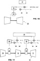
- Fig. 10 shows a single stage turbine 10' with only a single fuel blending system 30 as discussed above that is controlled by the controller 32 in order to reduce emissions or optimize performance using a fuel mixture of natural gas and hydrogen.
- the components that are functionally the same as for the reheat turbine 10 are indicated with the same reference numerals.
Description
- The present invention relates to the field of combustion technology for gas turbines.
- The investigation of hydrogen rich fuels has been ongoing for some time due to its significant environmental benefits. Somme examples are disclosed in documents
US 2004/0226299 ,EP1752709 ,US 2009/107105 ,EP2204561 . In particular two specific routes for hydrogen combustion have been widely investigated, these are: - 1. Combustion of technically pure hydrogen (hydrogen diluted with inerts such that the hydrogen is the dominant volumetric species) in the context of precombustion carbon capture.
- 2. Combustion of synthetic gasses (hydrogen and carbon monoxide blends) derived from the gasification of biological material providing a carbon neutral fuel.
- In both of these processes a fuel production facility would be used upstream of the gas turbine which would provide a continuous consistent supply of the fuel gas.
- However, a new context for the provision of hydrogen has been proposed. This approach stems from the fact that many renewable energy sources are capable of generating consistent quantities of electricity regardless of the demand for power. This leads to potentially excess electricity at off peak times and the potential for having to reduce generating capacity and the inability to increase production at peak load. It has been previously proposed that excess power can be used at off-peak times to produce hydrogen by the electrolysis that can be burnt with no carbon emissions when required.
- The obvious approach to utilize this fuel to provide peak power is through a gas turbine. As there are inefficiencies at each stage of' the conversion process it is clear that the efficiency of' the gas turbine must be maximized in order for the approach to be practical, which suggests the use of large scale combined cycle gas turbines. Such a unit would have a hydrogen consumption of approximately 6.5kg/s at base load. It is consequently probable that insufficient hydrogen would be available for sustained base load operation. It should also be noted that many alternative energy sources provide inconsistent power outputs (e.g. wind or wave generators) that would cause the available quantity to vary with time. It is therefore probable that the proposed gas turbine would have to operate with a varying mix of natural gas and hydrogen.
- In a reheat gas turbine two combustion systems, based on significantly different physical processes, are utilized. In the first system, fuel and air are premixed and a propagating flame is stabilized using carefully controlled aerodynamic structures. In the second combustion system vitiated air is mixed with the fuel. As the combustor inlet temperature is greater than the auto-ignition temperature of the fuel, combustion occurs after a characteristic delay time. As such, there is no need for complex aerodynamic flame stabilization devices as the flame will be self stabilizing at a predetermined location given by the flow velocity and the characteristic auto-ignition delay time.
- Due to the different stabilization mechanisms in the two combustors the influence of' using hydrogen within them differs. The aerodynamic stabilization used in the first combustor means the stability of this combustor can be influenced by changes in the burning velocity, which is strongly influenced by the fuel consumption and operating conditions. The auto-ignition delay time, the stabilizing factor in the reheat burner, is also influenced by these parameters but as the axial location of the flame can alter within the combustor with limited impact on performance the potential exists to design a reheat combustion system that can tolerate a range of' fuel compositions.
- It is also possible to control the flame location through adjusting the inlet temperature of the vitiated air entering the reheat combustor through the impact this parameter has on the auto-ignition delay time. This is only achievable by reducing the flame temperature in the first combustion system; therefore the extent to which this can be achieved is limited by the flame stability in this burner.
- Another characteristic of hydrogen fuel is that the auto-ignition delay time has a complex relationship with pressure initially falling as pressure is increased (in contrast to natural gas). This means that the use of hydrogen poses particular challenges during starting the engine. It has been known to use up to 5% hydrogen for emissions and LBO (lean blow off) improvement.
- A gas turbine is operated using a varying blend of a first fuel, preferably natural gas, and a second fuel comprising hydrogen. The hydrogen concentration is varied depending on operating conditions in order to reduce emissions of CO and NOx, and/or to mitigate LBO. The fuel mixture is varied using a controller based on a combination of factors in a modular operation concept to address different issues according to relevant load limitations. A method of operating a gas turbine according to this modular operational concept is also provided.
- In one aspect, a multi-stage gas turbine operating with a reheat cycle is used to burn a varying blend of natural gas and hydrogen, depending on the availability of hydrogen and the operating conditions. Different concentrations of hydrogen can be utilized in the two combustion systems. The fuel used in the second combustor is enriched with the required concentration of hydrogen, with the appropriate flame position being achieved by adjusting the inlet temperature to the second combustor to improve LBO. As the required flame temperature of the first combustor is reduced, the stability range can be increased by the addition of a controlled amount of hydrogen to the fuel. Additionally, NOx and CO emissions can be reduced.
- In one aspect of the invention, up to 20% hydrogen is added to the natural gas fuel for reduced NOx emission at baseload conditions. The NOx reduction appears to be due to improvement in the mixing quality due to increased turbulence and diffusivity caused by the addition of hydrogen. There is also a prompt reduction due to the hydrogen addition. Further reductions can be indirectly achieved by operating at a lower stage 1 ratio.
- In another aspect, up to 20% hydrogen is added to the natural gas fuel to reduce CO emissions at partial load conditions. This appears to be due to more reactivity of the fuel air mixture as well as possibly more OH radicals being generated for CO oxidation.
- In another aspect, addition of 30% or more hydrogen is added to the natural gas fuel to improve LBO.
- This can be used in connection with single as well as sequential combustors.
- Further, the hydrogen can be added based on a combination of the above-noted factors in a modular operation concept to address different issues according to relevant load limitations. For example, higher hydrogen can be used at idle for LBO mitigation; intermediate hydrogen addition can be used at partial load conditions for CO and NOx emission reduction; and low hydrogen addition in combination with a decreased S1 R (Stage 1 Ratio) can be utilized at baseload for low NOx emissions.
- All such control actions are handled within the control system for the turbine based on the required and/or available hydrogen supply for the particular operating condition and objective.
- The following detailed description of the preferred embodiment of the present invention will be better understood when read in conjunction with the appended drawings. For the purpose of illustrating the invention, there are shown in the drawings embodiments which are presently preferred. It is understood, however, that the invention is not limited to the precise arrangements and instrumentalities shown. In the drawings:
-
Fig. 1 is a schematic view of a turbine with sequential combustion; -
Fig. 2 is a pressure - ignition delay time graph at the inlet of the reheat combustor; -
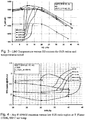
Fig. 3 is a graph showing LBO (lean blow off) versus hydrogen content for various S1 R (stage 1 ratios - which is the S1 fuel gas mass flow to total gas mass flow ration); -
Fig. 4 is a graph showing NOx emissions versus low S1 R ratio for various hydrogen concentrations; -
Fig. 5 is a graph showing NOx emissions versus high S1R ratio for various hydrogen concentrations; -
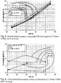
Fig. 6 is a graph showing CO emissions versus low S1 R ratio for various hydrogen concentrations; -
Fig. 7 is a graph showing CO emissions versus high S1 R ratio for various hydrogen concentrations; -
Fig. 8 is a graph showing Zeta versus hydrogen content for various S1 R ratios in a lower region; -
Fig. 9 is a graph showing Zeta versus hydrogen content for various S1 R ratios in a higher region; -
Fig. 10 is a diagram of a single stage gas turbine operating with a blend of natural gas and hydrogen that is controlled depending on hydrogen availability and/or operating conditions; and -
Fig. 11 is a diagram of a multi-stage gas turbine operating with a reheat cycle to burn a blend of natural gas and hydrogen that is controlled depending on hydrogen availability and/or operating conditions. - The disclosure deals with current and future capability to burn hydrogen enriched natural gas as a means of utilizing excess renewable generating capacity during off-peak periods. It relates to an operating method for the operation of an industrial gas turbine with a hydrogen enriched natural gas fuel and/or a diluted hydrogen fuel.
-
Fig. 1 shows areheat gas turbine 10 with acompressor 12, high pressure and low pressure outputturbine blade sections annular combustors combustors fuel lances respective chambers Fig. 11 , the fuel is blended infuel blending systems 30, 30', preferably mixing chambers, associated with each turbine stage in which varying amounts of natural gas and hydrogen are mixed depending on operating conditions and/or the availability of hydrogen required for one or bothcombustors controller 32, which can be a programmable logic controller (pic) or computer based controller that controlsservo valves 34, 34' for natural gas for each turbine stage andservo valves 36, 36' for hydrogen. The fuel is fed to either or both of thecombustors Figs. 1 and11 .Burners 26 are provided to ignite the fuel/compressed air mixture in the firstannular combustor 18, while the second (reheat)combustor 20 receives hot gases from thefirst combustor 18 at a high enough temperature to auto-ignite the additional fuel. Separatefuel blending systems 30, 30' allow thecombustors - The operating method for a
turbine 10 provides different stabilization mechanisms utilized within the two stage combustion system of areheat gas turbine 10, flexibility inherent in a reheat turbine as to which point in the operating cycle the reheat burner operates, and hydrogen to increase fuel reactivity, and hence burner stability, when operating thereheat combustor 20 at low inlet temperatures or part load. - The reactivity of hydrogen fuel at temperatures characteristic of the inlet of a reheat combustor decreases with increasing pressure (i.e. load) as shown in
Fig. 2 . This is opposite to the trend of natural gas. This behavior of hydrogen reactivity causes a significant difficulty in the design of reheat combustion hardware, as it is impossible to optimize both for base load operation and run-up safety. For this reason it is proposed that theturbine 10 is started on natural gas with hydrogen only being introduced to thereheat combustor 20 when a threshold pressure (i.e. load) has been exceeded. - For any fuel the time required for spontaneous ignition is strongly related to the temperature of the reactants. For this reason if, in a
reheat combustor 20, highly reactive fuels need to be utilized this often requires the reduction of the inlet temperature of the hot gas. In general the gas turbine is operated in such a way that the vitiated air at the injection plane is maintained at a specific temperature defined in the control algorithm. - Here, instead of being fixed the temperature set point defined in the control program is adjusted in real time to accommodate changes in the reactivity of the fuel (driven by fuel composition changes). Such changes would be handled automatically by the
controller 32 by using suitable operating maps defining an appropriate inlet temperature for a given composition. The fuel composition can be identified either by real time monitoring of a time varying fuel with an instrument such as a gas chromatograph. Alternatively where the fuel is blended from two or more sources the output from flow meters in the individual streams may be monitored to determine the composition at inlet to the burner. - In most premixed burners, flame stabilization is achieved by introducing complex aerodynamic structures that balance the speed at which the flame front attempts to propagate into the premixed reactants. For this reason it is possible to cause the flame to stabilize in free space. The speed at which the flame propagates is a function, among other parameters, of the composition of the reactants, and in particular the fuel type and oxidant concentration. It is thus possible to produce an operating point (whether by the choice of fuel, or by limiting the oxidant availability (e.g. flue gas recirculation), or by alternative means) where a significant imbalance exists between the velocity in the flow field and the propagation speed of the flame, such that the flame velocity is lower than the flow velocity. In this situation the flame will cease to be stable and be extinguished.
- Due to the high flame propagation speed of hydrogen, the
controller 32 allows such flame instabilities to be avoided by adding an appropriate concentration of hydrogen to the fuel. Here, at operating conditions under which flame stability is an issue, hydrogen is added to the fuel flow to restore stability. It is further provided that the amount of hydrogen to be added can be identified automatically by an engine control algorithm based on suitable maps identifying the required hydrogen to stabilize the operating point. - The
gas turbine 10 can be started on natural gas using thefirst stage combustor 18. The engine would run up to an operating point (approximately 6 to 8 bar) at which the increased reactivity of hydrogen at lower pressures is no longer apparent prior to the starting of the reheat combustion system. - The proportion of hydrogen in the fuel for the
reheat combustor 20 is selected automatically by thecontroller 32. A wide range of differing hydrogen compositions can be accommodated by automatically applying a map of reheat burner inlet temperature against hydrogen composition, i.e. if a high hydrogen concentration is required this can be accommodated by de-rating the inlet temperature. - As the inlet temperature of the
reheat combustor 20 is reduced, the potential for stability issues within thefirst stage combustor 18 could become apparent. This can be resolved by thecontroller 32 adding a small proportion of hydrogen, again based on an automatic operational map, to theprimary combustor 18 to increase reactivity and hence extend the proportion of hydrogen that can be accommodated. - The
controller 32 can also control the amount of hydrogen being added in order to control LBO. As shown inFig. 3 , the addition of hydrogen of about 20% or more of the fuel volume improves LBO.Figs. 4 and5 show that there is a significant reduction in NOx emissions for hydrogen content of up to 20%. A further improvement can be obtained in NOx emissions by operating with a lower S1R (stage 1 ratio= fuel gas mass flow/total gas mass flow) than in a turbine running on natural gas alone. - The
controller 32 can also be used to lower CO emissions by the addition of hydrogen preferably in the 20% to 40% range, as shown inFigs. 6 and7 . This is believed to be due to increased fuel reactivity and OH radical formation. This effect is important at high pressures. -
Figs. 8 and9 show that pressure drop (zeta) is stable for hydrogen up to about 20%. Above 20% a modest increase in zeta is observed. - Based on this, the
controller 32 can operate to optimize certain performance characteristics depending on operating conditions. Hydrogen is preferably added to the fuel mixture to about 20% for the baseload condition to reduce emissions of NOx and CO. At part load conditions, 20% hydrogen is added to the fuel mixture to continue to reduce CO emissions. 30% or more hydrogen can be added to the fuel mix to improve LBO conditions, with some sacrifice in other areas. As previously noted, the addition of the hydrogen to the fuel mix can be used in both single or reheat combustors. Forreheat combustors 20, the hydrogen addition to the fuel mix can be controlled separately for the first andsecond stage combustors controller 32 preferably utilizes a modular operation concept so that the controlled addition of hydrogen is done at different times to address different issues, with higher hydrogen (30% or more) addition at idle for LBO mitigation, intermediate hydrogen addition (10% to 30%) at part load to reduce CO and NOx emissions, and low hydrogen addition and a decreased S1 R at baseload for low NOx. This fuel modulation generally does not affect pressure drop, so no impact on engine performance is anticipated. -
Fig. 10 shows a single stage turbine 10' with only a singlefuel blending system 30 as discussed above that is controlled by thecontroller 32 in order to reduce emissions or optimize performance using a fuel mixture of natural gas and hydrogen. The components that are functionally the same as for thereheat turbine 10 are indicated with the same reference numerals. - It is understood, therefore, that this invention is not limited to the particular embodiments disclosed, but is intended to cover all modifications which are within the spirit and scope of the invention as defined by the appended claims; the above description; and/or shown in the attached drawings.
Claims (11)
- A method for operating a gas turbine comprising:starting up the turbine (10) by feeding a first fuel to a first combustor (18) for a first output turbine section (14);the method being characterized by comprising the steps of:• supplying a first fuel mix to the first combustor (18) and a second fuel mix to a second combustor (20) for a second output blade section (16) when a threshold pressure has been exceeded; wherein the first fuel mix and the second fuel mix are obtained by adding a second fuel to the first fuel; the second fuel comprising hydrogen; the first fuel mix and the second fuel mix being the same or different;• varying the amount of hydrogen of the second fuel on the basis of the operating conditions of the turbine (10) in order to reduce at least one of NOx emissions or CO emissions.
- The method of claim 1, wherein the step of varying the amount of hydrogen comprising adding to the second fuel at least 30% hydrogen at idle to improve lean blow off (LBO).
- The method of claim 1, wherein the step of varying the amount of hydrogen comprising adding to the second fuel between 10% to 30% hydrogen to improve emissions of NOx and CO.
- The method of claim 1, wherein the step of varying the amount of hydrogen comprising adding to the second fuel about 10% hydrogen at baseload to reduce NOx emissions.
- The method of claim 1, wherein the threshold pressure is a pressure of 6 - 8 bar.
- The method of claim 2, wherein the step of varying the amount of hydrogen of the second fuel comprise selecting the amount of hydrogen on the basis of a reheat burner inlet temperature in view of a hydrogen composition.
- A multi-stage gas turbine (10) comprising• a compressor (12),• a first combustor (18) in communication with the compressor (12),• a second combustor (20);• a first output turbine blade section (14) downstream of the first combustor (18) and upstream of the second combustor (20);• a second output turbine blade section (16) downstream of the second combustor (20) and in communication with the second combustor (20);• a first blending system (30) configured for blending a first fuel and a second fuel and for providing a first fuel mix to the first combustor (18);• a second blending system (30') configured for blending the first fuel and the second fuel and for providing a second fuel mix to the second combustor (20);• the second fuel comprising hydrogen; the first fuel mix and the second fuel mix being the same or different;• first fuel supply valves (34, 34') for providing the first fuel to the first blending system (30) and to the second blending system (30');• second fuel supply valves (36, 36') for providing the second fuel to the first blending system (30) and to the second blending system (30');the multistage gas turbine being characterized by comprising a controller (32) configured for:• regulating the first fuel supply valves (34, 34') and the second fuel supply valves (36, 36') in order to supply only the first fuel to the first combustor (18) during the start of the turbine when a threshold pressure is not exceeded and to supply the first fuel mix to the first combustor (18) and the second fuel mix to the second combustor (20) when the threshold pressure is exceeded; and• regulating the second fuel supply valves (36, 36') for varying the amount of hydrogen of the second fuel on the basis of the operating conditions of the turbine (10) in order to reduce at least one of NOx emissions or CO emissions.
- The gas turbine of claim 7, wherein the first output turbine blade section (14) is a high pressure turbine and the second output turbine blade section (16) is a low pressure turbine.
- The gas turbine of claim 7, wherein the first fuel supply valves (34, 34') and the second fuel supply valves (36, 36') are servo valves.
- The gas turbine of claim 7, wherein the controller (32) is a programmable logic controller or a computer-based controller.
- The gas turbine of claim 7, wherein the first blending system (30) and the second blending systems (30') operate independently from one another.
Applications Claiming Priority (1)
| Application Number | Priority Date | Filing Date | Title |
|---|---|---|---|
| US201161546321P | 2011-10-12 | 2011-10-12 |
Publications (4)
| Publication Number | Publication Date |
|---|---|
| EP2581561A2 EP2581561A2 (en) | 2013-04-17 |
| EP2581561A3 EP2581561A3 (en) | 2016-01-06 |
| EP2581561B1 true EP2581561B1 (en) | 2017-03-01 |
| EP2581561B8 EP2581561B8 (en) | 2017-07-12 |
Family
ID=47080302
Family Applications (1)
| Application Number | Title | Priority Date | Filing Date |
|---|---|---|---|
| EP12188148.6A Active EP2581561B8 (en) | 2011-10-12 | 2012-10-11 | Operating method for hydrogen /natural gas blends within a reheat gas turbine and gas turbine |
Country Status (2)
| Country | Link |
|---|---|
| US (1) | US20130091852A1 (en) |
| EP (1) | EP2581561B8 (en) |
Families Citing this family (10)
| Publication number | Priority date | Publication date | Assignee | Title |
|---|---|---|---|---|
| US9869190B2 (en) | 2014-05-30 | 2018-01-16 | General Electric Company | Variable-pitch rotor with remote counterweights |
| US10072510B2 (en) | 2014-11-21 | 2018-09-11 | General Electric Company | Variable pitch fan for gas turbine engine and method of assembling the same |
| US10126015B2 (en) | 2014-12-19 | 2018-11-13 | Carrier Corporation | Inward fired pre-mix burners with carryover |
| US10100653B2 (en) | 2015-10-08 | 2018-10-16 | General Electric Company | Variable pitch fan blade retention system |
| US11161076B1 (en) | 2020-08-26 | 2021-11-02 | Next Carbon Solutions, Llc | Devices, systems, facilities, and processes of liquid natural gas processing for power generation |
| US11067335B1 (en) | 2020-08-26 | 2021-07-20 | Next Carbon Soiittions, Llc | Devices, systems, facilities, and processes for liquefied natural gas production |
| US11112174B1 (en) | 2020-08-26 | 2021-09-07 | Next Carbon Solutions, Llc | Devices, systems, facilities, and processes for liquefied natural gas production |
| US11674435B2 (en) | 2021-06-29 | 2023-06-13 | General Electric Company | Levered counterweight feathering system |
| US11795964B2 (en) | 2021-07-16 | 2023-10-24 | General Electric Company | Levered counterweight feathering system |
| US11852082B2 (en) | 2022-01-05 | 2023-12-26 | General Electric Company | Systems and methods for controlling a fuel blend for a gas turbine |
Family Cites Families (16)
| Publication number | Priority date | Publication date | Assignee | Title |
|---|---|---|---|---|
| US3766734A (en) * | 1972-03-01 | 1973-10-23 | Gen Electric | Dual fuel control system for a gas turbine |
| US4761948A (en) * | 1987-04-09 | 1988-08-09 | Solar Turbines Incorporated | Wide range gaseous fuel combustion system for gas turbine engines |
| CH688899A5 (en) * | 1994-05-26 | 1998-05-15 | Asea Brown Boveri | A method for controlling a gas turbine group. |
| US6640548B2 (en) * | 2001-09-26 | 2003-11-04 | Siemens Westinghouse Power Corporation | Apparatus and method for combusting low quality fuel |
| US20040226299A1 (en) * | 2003-05-12 | 2004-11-18 | Drnevich Raymond Francis | Method of reducing NOX emissions of a gas turbine |
| US7624564B2 (en) * | 2004-07-23 | 2009-12-01 | Power Systems Mfg., Llc | Apparatus and method for providing an off-gas to a combustion system |
| JP4728176B2 (en) * | 2005-06-24 | 2011-07-20 | 株式会社日立製作所 | Burner, gas turbine combustor and burner cooling method |
| US20070033945A1 (en) * | 2005-08-10 | 2007-02-15 | Goldmeer Jeffrey S | Gas turbine system and method of operation |
| US8056344B2 (en) * | 2007-09-25 | 2011-11-15 | Airbus Sas | Gas turbine engine and method for reducing turbine engine combustor gaseous emission |
| US9080513B2 (en) * | 2007-10-31 | 2015-07-14 | General Electric Company | Method and apparatus for combusting syngas within a combustor |
| US8122725B2 (en) * | 2007-11-01 | 2012-02-28 | General Electric Company | Methods and systems for operating gas turbine engines |
| EP2220438B1 (en) * | 2007-11-27 | 2019-07-24 | Ansaldo Energia Switzerland AG | Method for operating a combined cycle power plant having a gas turbine installation using a second, hydrogen-rich fuel |
| EP2116768B1 (en) * | 2008-05-09 | 2016-07-27 | Alstom Technology Ltd | Burner |
| US7895821B2 (en) * | 2008-12-31 | 2011-03-01 | General Electric Company | System and method for automatic fuel blending and control for combustion gas turbine |
| US20100175386A1 (en) * | 2009-01-09 | 2010-07-15 | General Electric Company | Premixed partial oxidation syngas generation and gas turbine system |
| US20120102967A1 (en) * | 2010-10-27 | 2012-05-03 | General Electric Company | Method and system for preventing combustion instabilities during transient operations |
-
2012
- 2012-10-11 US US13/649,502 patent/US20130091852A1/en not_active Abandoned
- 2012-10-11 EP EP12188148.6A patent/EP2581561B8/en active Active
Non-Patent Citations (1)
| Title |
|---|
| None * |
Also Published As
| Publication number | Publication date |
|---|---|
| EP2581561B8 (en) | 2017-07-12 |
| EP2581561A3 (en) | 2016-01-06 |
| US20130091852A1 (en) | 2013-04-18 |
| EP2581561A2 (en) | 2013-04-17 |
Similar Documents
| Publication | Publication Date | Title |
|---|---|---|
| EP2581561B1 (en) | Operating method for hydrogen /natural gas blends within a reheat gas turbine and gas turbine | |
| US7624564B2 (en) | Apparatus and method for providing an off-gas to a combustion system | |
| CA2829613C (en) | Method for operating a gas turbine with sequential combustion and gas turbine for conducting said method | |
| US8117823B2 (en) | Method and system for increasing modified wobbe index control range | |
| US20130327050A1 (en) | Controlling flame stability of a gas turbine generator | |
| US9500127B2 (en) | Power plant and method for its operation | |
| CN106481451B (en) | Gas turbine with sequential combustion assembly and fuel composition controller | |
| JP2011252494A (en) | Gas turbine combustion system with rich premixed fuel reforming and method of use thereof | |
| US9170023B2 (en) | Operation of a gas turbine | |
| EP1862529A2 (en) | Hydrogen blended combustion system with flue gas recirculation | |
| US20120159959A1 (en) | System and Method for Fuel and Air Mixing in a Gas Turbine | |
| Banihabib et al. | Development and testing of a 100 kW fuel-flexible micro gas turbine running on 100% hydrogen | |
| RU2749287C1 (en) | Method for operating gas turbine and computer-readable storage medium for implementation thereof | |
| CN111623372B (en) | Method for operating a sequential burner and gas turbine comprising a sequential burner | |
| WO2023138897A1 (en) | Gas turbine system with diffusion-flame combustion and fuel blending for reducing undesired emissions | |
| EP4116555A1 (en) | Operating method and retrofitting method for a gas turbine | |
| EP4191037A1 (en) | Gas turbine engine and method for operating same | |
| CN112344370A (en) | Sequential combustor assembly for a gas turbine assembly and method of operating the same | |
| CN112344369A (en) | Gas turbine assembly comprising sequential combustor and method of operating the same |
Legal Events
| Date | Code | Title | Description |
|---|---|---|---|
| PUAI | Public reference made under article 153(3) epc to a published international application that has entered the european phase |
Free format text: ORIGINAL CODE: 0009012 |
|
| AK | Designated contracting states |
Kind code of ref document: A2 Designated state(s): AL AT BE BG CH CY CZ DE DK EE ES FI FR GB GR HR HU IE IS IT LI LT LU LV MC MK MT NL NO PL PT RO RS SE SI SK SM TR |
|
| AX | Request for extension of the european patent |
Extension state: BA ME |
|
| RIN1 | Information on inventor provided before grant (corrected) |
Inventor name: POYYAPAKKAM, MADHAVAN Inventor name: WOOD, JOHN PHILIP Inventor name: EROGLU, ADNAN Inventor name: GENIN, FRANKLIN MARIE Inventor name: SYED, KHAWAR Inventor name: CIANI, ANDREA Inventor name: LACHAUX, THIERRY |
|
| RIC1 | Information provided on ipc code assigned before grant |
Ipc: F02C 9/40 20060101ALI20150910BHEP Ipc: F02C 9/34 20060101ALI20150910BHEP Ipc: F01D 19/00 20060101AFI20150910BHEP Ipc: F02C 3/20 20060101ALI20150910BHEP |
|
| PUAL | Search report despatched |
Free format text: ORIGINAL CODE: 0009013 |
|
| AK | Designated contracting states |
Kind code of ref document: A3 Designated state(s): AL AT BE BG CH CY CZ DE DK EE ES FI FR GB GR HR HU IE IS IT LI LT LU LV MC MK MT NL NO PL PT RO RS SE SI SK SM TR |
|
| AX | Request for extension of the european patent |
Extension state: BA ME |
|
| RIC1 | Information provided on ipc code assigned before grant |
Ipc: F01D 19/00 20060101AFI20151127BHEP Ipc: F02C 9/34 20060101ALI20151127BHEP Ipc: F02C 9/40 20060101ALI20151127BHEP Ipc: F02C 3/20 20060101ALI20151127BHEP |
|
| 17P | Request for examination filed |
Effective date: 20160706 |
|
| RAP1 | Party data changed (applicant data changed or rights of an application transferred) |
Owner name: GENERAL ELECTRIC TECHNOLOGY GMBH |
|
| RBV | Designated contracting states (corrected) |
Designated state(s): AL AT BE BG CH CY CZ DE DK EE ES FI FR GB GR HR HU IE IS IT LI LT LU LV MC MK MT NL NO PL PT RO RS SE SI SK SM TR |
|
| GRAP | Despatch of communication of intention to grant a patent |
Free format text: ORIGINAL CODE: EPIDOSNIGR1 |
|
| INTG | Intention to grant announced |
Effective date: 20160926 |
|
| GRAS | Grant fee paid |
Free format text: ORIGINAL CODE: EPIDOSNIGR3 |
|
| GRAA | (expected) grant |
Free format text: ORIGINAL CODE: 0009210 |
|
| AK | Designated contracting states |
Kind code of ref document: B1 Designated state(s): AL AT BE BG CH CY CZ DE DK EE ES FI FR GB GR HR HU IE IS IT LI LT LU LV MC MK MT NL NO PL PT RO RS SE SI SK SM TR |
|
| REG | Reference to a national code |
Ref country code: GB Ref legal event code: FG4D |
|
| REG | Reference to a national code |
Ref country code: CH Ref legal event code: EP Ref country code: AT Ref legal event code: REF Ref document number: 871614 Country of ref document: AT Kind code of ref document: T Effective date: 20170315 |
|
| REG | Reference to a national code |
Ref country code: IE Ref legal event code: FG4D |
|
| REG | Reference to a national code |
Ref country code: DE Ref legal event code: R096 Ref document number: 602012029151 Country of ref document: DE |
|
| RAP2 | Party data changed (patent owner data changed or rights of a patent transferred) |
Owner name: ANSALDO ENERGIA IP UK LIMITED |
|
| REG | Reference to a national code |
Ref country code: NL Ref legal event code: MP Effective date: 20170301 |
|
| REG | Reference to a national code |
Ref country code: LT Ref legal event code: MG4D |
|
| REG | Reference to a national code |
Ref country code: AT Ref legal event code: MK05 Ref document number: 871614 Country of ref document: AT Kind code of ref document: T Effective date: 20170301 |
|
| PG25 | Lapsed in a contracting state [announced via postgrant information from national office to epo] |
Ref country code: HR Free format text: LAPSE BECAUSE OF FAILURE TO SUBMIT A TRANSLATION OF THE DESCRIPTION OR TO PAY THE FEE WITHIN THE PRESCRIBED TIME-LIMIT Effective date: 20170301 Ref country code: GR Free format text: LAPSE BECAUSE OF FAILURE TO SUBMIT A TRANSLATION OF THE DESCRIPTION OR TO PAY THE FEE WITHIN THE PRESCRIBED TIME-LIMIT Effective date: 20170602 Ref country code: FI Free format text: LAPSE BECAUSE OF FAILURE TO SUBMIT A TRANSLATION OF THE DESCRIPTION OR TO PAY THE FEE WITHIN THE PRESCRIBED TIME-LIMIT Effective date: 20170301 Ref country code: LT Free format text: LAPSE BECAUSE OF FAILURE TO SUBMIT A TRANSLATION OF THE DESCRIPTION OR TO PAY THE FEE WITHIN THE PRESCRIBED TIME-LIMIT Effective date: 20170301 Ref country code: NO Free format text: LAPSE BECAUSE OF FAILURE TO SUBMIT A TRANSLATION OF THE DESCRIPTION OR TO PAY THE FEE WITHIN THE PRESCRIBED TIME-LIMIT Effective date: 20170601 |
|
| PG25 | Lapsed in a contracting state [announced via postgrant information from national office to epo] |
Ref country code: LV Free format text: LAPSE BECAUSE OF FAILURE TO SUBMIT A TRANSLATION OF THE DESCRIPTION OR TO PAY THE FEE WITHIN THE PRESCRIBED TIME-LIMIT Effective date: 20170301 Ref country code: RS Free format text: LAPSE BECAUSE OF FAILURE TO SUBMIT A TRANSLATION OF THE DESCRIPTION OR TO PAY THE FEE WITHIN THE PRESCRIBED TIME-LIMIT Effective date: 20170301 Ref country code: SE Free format text: LAPSE BECAUSE OF FAILURE TO SUBMIT A TRANSLATION OF THE DESCRIPTION OR TO PAY THE FEE WITHIN THE PRESCRIBED TIME-LIMIT Effective date: 20170301 Ref country code: BG Free format text: LAPSE BECAUSE OF FAILURE TO SUBMIT A TRANSLATION OF THE DESCRIPTION OR TO PAY THE FEE WITHIN THE PRESCRIBED TIME-LIMIT Effective date: 20170601 Ref country code: ES Free format text: LAPSE BECAUSE OF FAILURE TO SUBMIT A TRANSLATION OF THE DESCRIPTION OR TO PAY THE FEE WITHIN THE PRESCRIBED TIME-LIMIT Effective date: 20170301 Ref country code: AT Free format text: LAPSE BECAUSE OF FAILURE TO SUBMIT A TRANSLATION OF THE DESCRIPTION OR TO PAY THE FEE WITHIN THE PRESCRIBED TIME-LIMIT Effective date: 20170301 |
|
| PG25 | Lapsed in a contracting state [announced via postgrant information from national office to epo] |
Ref country code: NL Free format text: LAPSE BECAUSE OF FAILURE TO SUBMIT A TRANSLATION OF THE DESCRIPTION OR TO PAY THE FEE WITHIN THE PRESCRIBED TIME-LIMIT Effective date: 20170301 |
|
| PG25 | Lapsed in a contracting state [announced via postgrant information from national office to epo] |
Ref country code: EE Free format text: LAPSE BECAUSE OF FAILURE TO SUBMIT A TRANSLATION OF THE DESCRIPTION OR TO PAY THE FEE WITHIN THE PRESCRIBED TIME-LIMIT Effective date: 20170301 Ref country code: CZ Free format text: LAPSE BECAUSE OF FAILURE TO SUBMIT A TRANSLATION OF THE DESCRIPTION OR TO PAY THE FEE WITHIN THE PRESCRIBED TIME-LIMIT Effective date: 20170301 Ref country code: SK Free format text: LAPSE BECAUSE OF FAILURE TO SUBMIT A TRANSLATION OF THE DESCRIPTION OR TO PAY THE FEE WITHIN THE PRESCRIBED TIME-LIMIT Effective date: 20170301 Ref country code: RO Free format text: LAPSE BECAUSE OF FAILURE TO SUBMIT A TRANSLATION OF THE DESCRIPTION OR TO PAY THE FEE WITHIN THE PRESCRIBED TIME-LIMIT Effective date: 20170301 |
|
| PG25 | Lapsed in a contracting state [announced via postgrant information from national office to epo] |
Ref country code: SM Free format text: LAPSE BECAUSE OF FAILURE TO SUBMIT A TRANSLATION OF THE DESCRIPTION OR TO PAY THE FEE WITHIN THE PRESCRIBED TIME-LIMIT Effective date: 20170301 Ref country code: PT Free format text: LAPSE BECAUSE OF FAILURE TO SUBMIT A TRANSLATION OF THE DESCRIPTION OR TO PAY THE FEE WITHIN THE PRESCRIBED TIME-LIMIT Effective date: 20170703 Ref country code: PL Free format text: LAPSE BECAUSE OF FAILURE TO SUBMIT A TRANSLATION OF THE DESCRIPTION OR TO PAY THE FEE WITHIN THE PRESCRIBED TIME-LIMIT Effective date: 20170301 Ref country code: IS Free format text: LAPSE BECAUSE OF FAILURE TO SUBMIT A TRANSLATION OF THE DESCRIPTION OR TO PAY THE FEE WITHIN THE PRESCRIBED TIME-LIMIT Effective date: 20170701 |
|
| REG | Reference to a national code |
Ref country code: DE Ref legal event code: R097 Ref document number: 602012029151 Country of ref document: DE |
|
| PLBE | No opposition filed within time limit |
Free format text: ORIGINAL CODE: 0009261 |
|
| STAA | Information on the status of an ep patent application or granted ep patent |
Free format text: STATUS: NO OPPOSITION FILED WITHIN TIME LIMIT |
|
| PG25 | Lapsed in a contracting state [announced via postgrant information from national office to epo] |
Ref country code: DK Free format text: LAPSE BECAUSE OF FAILURE TO SUBMIT A TRANSLATION OF THE DESCRIPTION OR TO PAY THE FEE WITHIN THE PRESCRIBED TIME-LIMIT Effective date: 20170301 |
|
| 26N | No opposition filed |
Effective date: 20171204 |
|
| PG25 | Lapsed in a contracting state [announced via postgrant information from national office to epo] |
Ref country code: SI Free format text: LAPSE BECAUSE OF FAILURE TO SUBMIT A TRANSLATION OF THE DESCRIPTION OR TO PAY THE FEE WITHIN THE PRESCRIBED TIME-LIMIT Effective date: 20170301 |
|
| PGFP | Annual fee paid to national office [announced via postgrant information from national office to epo] |
Ref country code: GB Payment date: 20171019 Year of fee payment: 6 |
|
| PG25 | Lapsed in a contracting state [announced via postgrant information from national office to epo] |
Ref country code: MC Free format text: LAPSE BECAUSE OF FAILURE TO SUBMIT A TRANSLATION OF THE DESCRIPTION OR TO PAY THE FEE WITHIN THE PRESCRIBED TIME-LIMIT Effective date: 20170301 |
|
| REG | Reference to a national code |
Ref country code: CH Ref legal event code: PL |
|
| REG | Reference to a national code |
Ref country code: IE Ref legal event code: MM4A |
|
| REG | Reference to a national code |
Ref country code: FR Ref legal event code: ST Effective date: 20180629 |
|
| PG25 | Lapsed in a contracting state [announced via postgrant information from national office to epo] |
Ref country code: CH Free format text: LAPSE BECAUSE OF NON-PAYMENT OF DUE FEES Effective date: 20171031 Ref country code: LI Free format text: LAPSE BECAUSE OF NON-PAYMENT OF DUE FEES Effective date: 20171031 Ref country code: LU Free format text: LAPSE BECAUSE OF NON-PAYMENT OF DUE FEES Effective date: 20171011 |
|
| REG | Reference to a national code |
Ref country code: BE Ref legal event code: MM Effective date: 20171031 |
|
| PG25 | Lapsed in a contracting state [announced via postgrant information from national office to epo] |
Ref country code: FR Free format text: LAPSE BECAUSE OF NON-PAYMENT OF DUE FEES Effective date: 20171031 Ref country code: BE Free format text: LAPSE BECAUSE OF NON-PAYMENT OF DUE FEES Effective date: 20171031 |
|
| PG25 | Lapsed in a contracting state [announced via postgrant information from national office to epo] |
Ref country code: MT Free format text: LAPSE BECAUSE OF NON-PAYMENT OF DUE FEES Effective date: 20171011 |
|
| PG25 | Lapsed in a contracting state [announced via postgrant information from national office to epo] |
Ref country code: IE Free format text: LAPSE BECAUSE OF NON-PAYMENT OF DUE FEES Effective date: 20171011 |
|
| GBPC | Gb: european patent ceased through non-payment of renewal fee |
Effective date: 20181011 |
|
| PG25 | Lapsed in a contracting state [announced via postgrant information from national office to epo] |
Ref country code: HU Free format text: LAPSE BECAUSE OF FAILURE TO SUBMIT A TRANSLATION OF THE DESCRIPTION OR TO PAY THE FEE WITHIN THE PRESCRIBED TIME-LIMIT; INVALID AB INITIO Effective date: 20121011 |
|
| PG25 | Lapsed in a contracting state [announced via postgrant information from national office to epo] |
Ref country code: GB Free format text: LAPSE BECAUSE OF NON-PAYMENT OF DUE FEES Effective date: 20181011 Ref country code: CY Free format text: LAPSE BECAUSE OF NON-PAYMENT OF DUE FEES Effective date: 20170301 |
|
| PG25 | Lapsed in a contracting state [announced via postgrant information from national office to epo] |
Ref country code: MK Free format text: LAPSE BECAUSE OF FAILURE TO SUBMIT A TRANSLATION OF THE DESCRIPTION OR TO PAY THE FEE WITHIN THE PRESCRIBED TIME-LIMIT Effective date: 20170301 |
|
| PG25 | Lapsed in a contracting state [announced via postgrant information from national office to epo] |
Ref country code: TR Free format text: LAPSE BECAUSE OF FAILURE TO SUBMIT A TRANSLATION OF THE DESCRIPTION OR TO PAY THE FEE WITHIN THE PRESCRIBED TIME-LIMIT Effective date: 20170301 |
|
| PG25 | Lapsed in a contracting state [announced via postgrant information from national office to epo] |
Ref country code: AL Free format text: LAPSE BECAUSE OF FAILURE TO SUBMIT A TRANSLATION OF THE DESCRIPTION OR TO PAY THE FEE WITHIN THE PRESCRIBED TIME-LIMIT Effective date: 20170301 |
|
| PGFP | Annual fee paid to national office [announced via postgrant information from national office to epo] |
Ref country code: IT Payment date: 20221026 Year of fee payment: 11 Ref country code: DE Payment date: 20221019 Year of fee payment: 11 |