EP2392532A2 - Winder - Google Patents
Winder Download PDFInfo
- Publication number
- EP2392532A2 EP2392532A2 EP11166875A EP11166875A EP2392532A2 EP 2392532 A2 EP2392532 A2 EP 2392532A2 EP 11166875 A EP11166875 A EP 11166875A EP 11166875 A EP11166875 A EP 11166875A EP 2392532 A2 EP2392532 A2 EP 2392532A2
- Authority
- EP
- European Patent Office
- Prior art keywords
- contact roller
- yarns
- bobbin
- turret table
- tilt mechanism
- Prior art date
- Legal status (The legal status is an assumption and is not a legal conclusion. Google has not performed a legal analysis and makes no representation as to the accuracy of the status listed.)
- Granted
Links
Images



Classifications
-
- B—PERFORMING OPERATIONS; TRANSPORTING
- B65—CONVEYING; PACKING; STORING; HANDLING THIN OR FILAMENTARY MATERIAL
- B65H—HANDLING THIN OR FILAMENTARY MATERIAL, e.g. SHEETS, WEBS, CABLES
- B65H54/00—Winding, coiling, or depositing filamentary material
- B65H54/02—Winding and traversing material on to reels, bobbins, tubes, or like package cores or formers
- B65H54/40—Arrangements for rotating packages
- B65H54/52—Drive contact pressure control, e.g. pressing arrangements
-
- B—PERFORMING OPERATIONS; TRANSPORTING
- B65—CONVEYING; PACKING; STORING; HANDLING THIN OR FILAMENTARY MATERIAL
- B65H—HANDLING THIN OR FILAMENTARY MATERIAL, e.g. SHEETS, WEBS, CABLES
- B65H67/00—Replacing or removing cores, receptacles, or completed packages at paying-out, winding, or depositing stations
- B65H67/04—Arrangements for removing completed take-up packages and or replacing by cores, formers, or empty receptacles at winding or depositing stations; Transferring material between adjacent full and empty take-up elements
- B65H67/044—Continuous winding apparatus for winding on two or more winding heads in succession
- B65H67/048—Continuous winding apparatus for winding on two or more winding heads in succession having winding heads arranged on rotary capstan head
-
- B—PERFORMING OPERATIONS; TRANSPORTING
- B65—CONVEYING; PACKING; STORING; HANDLING THIN OR FILAMENTARY MATERIAL
- B65H—HANDLING THIN OR FILAMENTARY MATERIAL, e.g. SHEETS, WEBS, CABLES
- B65H2701/00—Handled material; Storage means
- B65H2701/30—Handled filamentary material
- B65H2701/31—Textiles threads or artificial strands of filaments
Definitions
- the present invention relates to a winder winding yarns onto bobbins.
- the winder of Japanese Unexamined Patent Publication No. 8-310723 is arranged so that bobbins attached to a cantilevered bobbin holder are caused to contact a contact roller (touch roller) extending in parallel to the bobbin holder, and yarns are wound onto the bobbins while a pressure is applied to the bobbins by the contact roller.
- a contact roller touch roller
- the winder of Japanese Unexamined Patent Publication No. 8-310723 is arranged so that, by detecting the contact pressure to each bobbin and by elongating or shortening an adjusting cylinder based on the detection result, the pressure applied to the contact roller is changed to tilt the contact roller to be substantially in parallel to the warped bobbin holder. As such, the contact pressures to the bobbins applied from the contact roller are equalized therebetween.
- An object of the present invention is to provide a winder in which improper winding of yarns and the breakdown of portions around the contact roller hardly occur even if a tilt unit by which the contact roller is tilted is broken.
- a winder includes: a bobbin holder which is cantilevered at a main body and to which a bobbin for winding yarns is attached; a contact roller which contacts the bobbin attached to the bobbin holder; and a tilt mechanism which tilts the contact roller in a vertical direction, wherein, the tilt mechanism is mechanically interlocked with a moving member which moves in accordance with a change in an amount of the yarns wound onto the bobbin, and the contact roller is tilted by utilizing the movement of the moving member.
- the tilt mechanism is mechanically interlocked with the moving member which is moved in accordance with a change in the amount of the yarns wound onto the bobbin, and the contact roller is tilted by utilizing the movement of the moving member. For this reason, even if a breakdown occurs, only the mechanical interlocking with the moving member becomes inactive and the tilting of the contact roller by utilizing the movement of the moving member is no longer possible, and hence the tilting angle of the contact roller is not rapidly changed. Therefore the above-described problems such as improper winding of yarns and the vibration of the contact roller hardly occur.
- the winder of the first aspect further includes a turret table which cantilevers the bobbin holder and moves the bobbin holder by rotating about a rotation axis which is in parallel to the axis of the bobbin holder, wherein, when the yarns are wound, the contact roller is maintained at a predetermined position, the turret table functions as the moving member in which the bobbin holder moves away from the contact roller as an amount of the yarns wound onto the bobbin increases, and the tilt mechanism is mechanically interlocked with the turret table and tilts the contact roller by utilizing the rotation of the turret table.
- the contact roller is maintained at a predetermined position. Furthermore, when the turret table is arranged to rotate in accordance with the increase in the amount of yarns on the bobbin so as to function as the moving member, the contact roller is tilted by utilizing the rotation of the turret table functioning as the moving member.
- the winder of the second aspect is arranged so that the tilt mechanism tilts the contact roller by transferring the rotation of the turret table to the contact roller and including: a cam which is provided on the turret table and has a cam surface which extends in a direction of the rotation of the turret table; and a cam rod which contacts the cam surface.
- the contact roller is tilted by transferring the rotation of the turret table to the contact roller via components such as the cam on the turret table and the cam rod on the cam surface.
- the winder of any one of the first to third aspects further includes a guide shaft which elevatably supports the contact roller, wherein, the tilt mechanism tilts the contact roller by tilting the guide shaft.
- the contact roller when the contact roller is elevatably supported by the guide shaft, the contact roller is tilted by tilting the guide shaft.
- the winder of the first aspect is arranged so that the contact roller is arranged to be moved by being pushed by the bobbin to which the yarns are wound, so as to function as the moving member, and the tilt mechanism is mechanically interlocked with the contact roller, and tilts the contact roller by utilizing the movement of the pushed contact roller.
- the contact roller is arranged to be moved by being pushed by the yarn wound onto the bobbin so as to function as the moving member, the contact roller is tilted by utilizing the movement of the contact roller which is the moving member.
- the winder of the fifth aspect is arranged so that the tilt mechanism includes a guide member which has a guide being tilted with respect to the vertical direction and tilts the contact roller by guiding the moving contact roller along the guide.
- the contact roller is tilted by guiding the contact roller, which is moved by being pushed by the yarns wound onto the bobbin, along the guide of the guide member which is tilted in the vertical direction.
- the tilt mechanism is mechanically interlocked with the moving member which is moved in accordance with a change in the amount of the yarns wound onto the bobbin, and the contact roller is tilted by utilizing the movement of the moving member. For this reason, even if a breakdown occurs, only the mechanical interlocking with the moving member becomes inactive and the tilting of the contact roller by utilizing the movement of the moving member is no longer possible, and hence the tilting angle of the contact roller is not rapidly changed. Therefore the above-described problems such as improper winding of yarns and the vibration of the contact roller hardly occur.
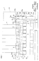
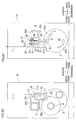
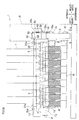
- Fig. 1 is an elevation of a winder of the present embodiment.
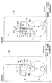
- Fig. 2A shows the winder of Fig. 1 viewed in the direction of the arrow IIA.
- Fig. 2B shows the winder of Fig. 1 viewed in the direction of the arrow IIB.
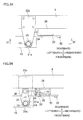
- Fig. 3A shows the winder of Fig. 1 viewed in the direction of the arrow III.
- Fig. 3B shows the winder of Fig. 3A from which the mounting member 22a and the swing axis 36 are removed.
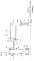
- Fig. 4 is a cross section taken along the IV-IV line of Fig. 3A . It is noted that, in Fig.
- a part of a base 10 of the winder 1 is indicated by a two-dot chain line to show the components inside the part indicated by the two-dot chain line.
- the position of the mounting member 22a is indicated by a two-dot chain line for easily understanding the positional relations of the components.
- the winder 1 includes components such as a base 10, two bobbin holders 2 attached to the base 10, a turret table 3, a contact pressure applying mechanism 4, and a tilt mechanism 5.
- Each of the two bobbin holders 2 is a substantially column shaped member cantilevered at the turret table 3.
- a plurality of substantially cylindrical bobbins B are attached to each bobbin holder 2 .
- Each bobbin holder 2 is rotated about a rotation axis 2a by an unillustrated motor, thereby yarns Y are wound onto the bobbins B attached to the bobbin holder 2 as described later.
- traverse units 7 are provided above the bobbins B attached to the bobbin holders 2, traverse units 7 are provided above the bobbins B attached to the bobbin holders 2, traverse units 7 are provided above the bobbins B attached to the bobbin holders 2, traverse units 7 are provided above each traverse unit 7 is provided a yarn guide 8. The yarns Y are therefore wound onto the bobbins B while being traversed on these yarn guides 8 in the crosswise directions by the traverse units 7.
- the traverse units 7 and the yarn guides 8 are provided on a later-described supporting
- the turret table 3 is a substantially circular plate and cantilevers the two bobbin holders 2 as described above and moves these bobbin holders 2 as the turret table 3 rotates about a rotation axis 3a which is in parallel to the axes of the bobbin holders 2.
- the positions of the two bobbin holders 2 are interchangeable. It is therefore possible to continuously wind yarns in such a way that the bobbins B attached to one bobbin holder 2 are replaced with new ones while yarns are wound onto the bobbins B attached to the other bobbin holder 2.
- the turret table 3 rotates during the winding of the yarns Y onto the bobbin B, in accordance with the increase in the amount of wound yarns Y.
- the contact pressure applying mechanism 4 includes components such as a contact roller 11 and a supporting member 12.
- the contact roller 11 extends substantially in parallel to the bobbin holders 2, and contacts the outer circumference of each bobbin holder 2 attached to one of the two bobbin holders 2, which is at a winding position. With this, a contact pressure is applied to the bobbins B by the contact roller 11, when the yarn Y are wound thereon.
- the supporting member 12 rotatably supports the both ends of the contact roller 11. At around the both ends of the supporting member 12, linear motion bearings 19 are provided, respectively. Into the linear motion bearings 19 are inserted vertically-extending guide shafts 13. The supporting member 12 is elevatable by an unillustrated elevator mechanism. As the supporting member 12 is vertically moved, the supporting member 12 and the contact roller 11 are also vertically moved along the guide shafts 13.
- Each guide shaft 13 is inserted into linear motion bearings 21a and 21b at the respective ends.
- the linear motion bearings 21a and 21b are attached to mounting members 22a and 22b fixed to the frame 6, respectively.
- Each of the linear motion bearings 21a and 21b has an internal diameter slightly larger than the diameter of each guide shaft 13. Between the linear motion bearing 21a and the guide shaft 13 inserted thereto, an O-ring 23 is provided. Similarly, between the linear motion bearing 21b and the guide shaft 13 inserted thereto, an O-ring 23 is provided. With this arrangement, the guide shafts 13 are swingable with respect to the linear motion bearings 21a and 21b fixed to the frame 6 (mounting members 22a and 22b).
- the tilt mechanism 5 is a mechanism for tilting the contact roller 11, and includes components such as cams 31, a cam rod 32, a force multiplying arm 33, a tie rod 34, and a tilt arm 35.
- the two cams 31 are provided on the side face of the turret table 3 to correspond to the respective bobbin holders 2.
- Each cam 31 extends along the circumferential direction of the turret table 3 as shown in Fig. 2B .
- the outer circumference of each cam 31, i.e. the cam surface 31a is arranged to be away from the rotation axis 3a of the turret table 3, toward the upstream in the clockwise direction in Fig. 2B .
- the cam rod 32 has at its lower end portion a roller 41 which contacts the cam surface 31a, and the upper end portion of the cam rod 32 is connected to the force multiplying arm 33.
- the cam rod 32 further includes a rod forming member 32a having the roller 41 and a rod forming member 32b connected to the force multiplying arm 33, and these two rod forming members 32a and 32b are vertically movable relative to each other.
- a spring 42 is provided between the rod forming member 32a and the rod forming member 32b. As a bolt 43 provided immediately above the spring 42 of the rod forming member 32b is tightened, the spring 42 is compressed.
- the spring 42 may not be provided. In such a case, a single component substitutes for the two rod forming members 32a and 32b of the cam rod 32.
- the force multiplying arm 33 is a substantially rectangular plate whose one end is attached to the cam rod 32 whereas the other end is attached to a swing axis 36 inserted into a bearing 37, so as to be swingable about the swing axis 36.
- a mounting shaft 38 is attached for mounting the tie rod 34.
- the tie rod 34 is mounted to be closer to the center of the swing axis 36 than the cam rod 32.
- the tie rod 34 is mounted between the force multiplying arm 33 and the tilt arm 35 to connect the force multiplying arm 33 with the tilt arm 35.
- the bearing 37 to which the swing axis 36 is inserted is fixed, in front of the tie rod 34, to a mounting plate 39 which is substantially C-shaped to sandwich the tie rod 34 from the front and rear sides.
- the mounting plate 39 is fixed to the frame 6 on the side opposite to the side where the bearing 37 is fixed, over the tie rod 34.
- a swing axis and a bearing similar to the swing axis 36 and the bearing 37 are provided at the portion where the frame 6 is fixed to the mounting plate 39. This swing axis is attached to the end of the mounting shaft 38 which end is opposite to the swing axis 36.
- the tilt arm 35 is a plate extending in the front-back directions, and is swingably supported at its substantially central portion by the swing axis 24 which is provided on the mounting member 22a.
- the tilt arm 35 is attached to the tie rod 34 at the trailing end portion, whereas a through hole 35a is formed at the leading end portion. To the through hole 35a is inserted the above-described guide shaft 13.
- Fig. 5 to Fig. 9 show the states during the yarn winding and are equivalent to Fig. 2 , Fig. 4 , Fig. 3B , and Fig. 1 , respectively.
- yarns Y When yarns Y are wound onto the bobbins B in the winder 1, yarns Y produced by an unillustrated spinning apparatus above the winder 1 are placed onto the bobbins B. As the bobbin holder 2 is rotated in this state, the yarns Y are wound onto the bobbins B while a contact pressure is applied to the bobbins B.
- each bobbin B gradually increases in accordance with the increase in the amount of the wound yarns Y. Taking into consideration of this, it is necessary to gradually increase the distance between the bobbin holder 2 and the contact roller 11.
- the supporting member 12 is not moved (i.e. the contact roller 11 is retained at a predetermined position) in the present embodiment.
- the distance between the bobbin holder 2 and the contact roller 11 is gradually increased by rotating the turret table 3 in the direction away from the contact roller 11 (i.e. the anticlockwise direction in Fig. 5A and the clockwise direction in Fig. 5B ) as the amount of yarns Y wound onto the bobbins B increases.
- each cam 31 is arranged so that the cam surface 31a is away from the rotation axis 3a of the turret table 3, toward the upstream in the clockwise direction in Fig. 2B . For this reason, as each cam 31 rotates, the cam rod 32 contacting the cam surface 31a of the cam 31 is pushed upward by the cam 31 as indicated by the arrow a.
- the force multiplying arm 33 rotates anticlockwise about the swing axis 36, thereby pulling the tie rod 34 attached to the force multiplying arm 33 toward the force multiplying arm 33 (i.e. rightward in the figure) as indicated by the arrow b.
- the tie rod 34 since in the force multiplying arm 33 the tie rod 34 is attached to be closer to the swing axis 36 than the cam rod 32 as described above, the moving distance of the tie rod 34 in response to the rotation of the force multiplying arm 33 caused by the movement of the cam rod 32 is shorter than the moving distance of the cam rod 32. Therefore, the force exerted from the force multiplying arm 33 to the tie rod 34 is greater than the force exerted from the cam rod 32 to the force multiplying arm 33.
- the trailing end portion of the tilt arm 35 connected to the tie rod 34 is also pulled toward the force multiplying arm 33 as indicated by the arrow b, with the result that the tilt arm 35 rotates clockwise about the swing axis 24.
- This rotation of the tilt arm 35 causes the leading end portion of the tilt arm 35, to which the guide shaft 13 inserted, to move in the direction (leftward in the figure) opposite to the movement of the trailing end portion, as indicated by the arrow c.
- the guide shaft 13 is pressed by the tilt arm 35 (i.e. the wall of the through hole 35a) and tilted. Therefore the supporting member 12 elevatable along the guide shaft 13 and the contact roller 11 supported by the supporting member 12 are tilted. In this state, the contact roller 11 is tilted in such a way that the part thereof corresponding to the leading end side of the bobbin holder 2 is positioned downward (in Fig. 8 , the tilting angle immediately before the completion of the winding is denoted as ⁇ ).
- the turret table 3 is the moving member of the present invention
- the tilt mechanism 5 constituted by the cams 31, the cam rod 32, the force multiplying arm 33,the tie rod 34, and the tilt arm 35 is mechanically interlocked with the turret table 3.
- the tilt mechanism 5 tilts the contact roller 11 by using the rotation of the turret table 3 which is the moving member.
- the tilting angle of the contact roller 11 increases.
- the bobbin holder 2 is warped downward toward the leading end remote from the part supported by the turret table 3, on account of the weight of the yarns Y.
- the degree of this warping increases as the amount of yarns Y wound onto the bobbins B increases.
- the contact roller 11 is not tilted, the bobbin B attached at the most leading end side of the bobbin holder 2 receives the least contact pressure from the contact roller 11, with the result that the diameters of the bobbins B are irregular between the left ones and the right ones when the winding of the yarns Y is completed.
- the contact roller 11 is tilted so that the part corresponding to the leading end side of the bobbin holder 2 is positioned downward, with the result that the bobbin holder 2 and the contact roller 11 are maintained to be more or less in parallel to each other and the distance between them is constant at all parts.
- the contact pressure between the contact roller 11 and each bobbin B is therefore constant and the diameter of each bobbin after the winding is constant.
- the tilt mechanism 5 mechanically interlocked with the turret table 3 tilts the contact roller 11 by transferring, to the guide shaft 13, the rotation of the turret table 3 which rotates in accordance with the increase in the amount of yarns Y wound onto the bobbins B. Because of this arrangement, even if a part of the tilt mechanism 5 is broken, merely the rotation of the turret table 3 is not transferred to the guide shaft 13 (i.e. the tilt mechanism 5 is no longer mechanically interlocked with the turret table 3) and the contact roller 11 is not tilted any more, and hence the contact roller 11 is maintained to have the position immediately before the breakdown of the tilt mechanism 5.
- the contact roller 11 has a certain amount of weight and hence a sufficiently large force is required to tilt the contact roller 11.
- the force applied from the force multiplying arm 33 to the tie rod 34 is larger than the force applied from the cam rod 32 to the force multiplying arm 33 as described above, it is possible to tilt the heavy contact roller 11 even if the force by which the cams 31 push the cam rod 32 is not so large.
- the rotation of the turret table 3 may be transferred to the guide shaft 13 by using a different mechanism.
- the contact roller 11 may be directly tilted without tilting the guide shaft 13 and the supporting member 12.
- the embodiment above is arranged so that, since the supporting member 12 supporting the contact roller 11 is elevatable, the contact roller 11 is caused to contact the bobbins B when the yarns Y are wound whereas the contact roller 11 is moved away from the bobbin holder 2 in cases such as the placement of the yarns.
- a different structure may be used for moving the contact roller 11 to contact or to be away from the bobbin holder 2.
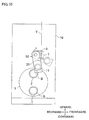
- the supporting member 51 supporting the contact roller 11 is provided with a swing axis 52.
- the respective ends of the swing axis 52 are inserted into bearings 53a and 53b, thereby allowing the supporting member 51 to be swingable about the swing axis 52.
- the contact roller 11 is moved between the position which is indicated by the full line in Fig. 10 and where the contact roller 11 contacts the bobbins B and the position which is indicated by the two-dot chain line in Fig. 10 and where the contact roller 11 is away from the bobbin holder 2.
- the bearings 53a and 53b are ball bearings, and the swing axis 52 is arranged to be swingable with respect to the bearings 53a and 53b.
- the bearing 53a is attached to an unillustrated frame or the like which is fixed to the base 10, whereas the bearing 53b is attached to the arm 54.
- the arm 54 is supported to be swingable about a swing axis 55 at an end thereof.
- This arm 54 is provided with the bearing 53b substantially at the center thereof, and is connected to the cam rod 32 at the end opposite to the swing axis 55.
- the arm 54 is arranged so that the bearing 53b is closer to the swing axis 55 than the cam rod 32.
- the turret table 3 rotates as the amount of yarns Y wound onto the bobbins B increases, wit the result that the cams 31 rotate and the cam rod 32 is pressed by the cams 31 and moved upward.
- the arm 54 is swung about the swing axis 55 and the bearing 53b attached to the arm 54 is pushed upward. This tilts the swing axis 52 which is inserted into the bearings 53a and 53b, the supporting member 51 supported by the swing axis 52, and the contact roller 11 supported by the supporting member 51.
- the contact roller 11 is tilted so that the part corresponding to the leading end side of the bobbin holder 2 is positioned downward.
- the cams 31, the cam rod 32, and the arm 54 for tilting the contact roller 11 are the tilt mechanism of the present invention.
- the bearing 53b is attached to be closer to the swing axis 55 than the cam rod 32, and hence the moving distance of the bearing 53b in response to the rotation of the arm 54 is shorter than the moving distance of the cam rod 32. Therefore the force applied from the arm 54 to the bearing 53b is larger than the force applied from the cam rod 32 to the arm 54, and hence the heavy contact roller 11 is tilted even if the force by which the cams 31 push the cam rod 32 is not so large.
- the embodiment above is arranged so that the distance between the bobbin holder 2 and the contact roller 11 is gradually increased by rotating the turret table 3 in accordance with the increase in the amount of yarns Y wound onto the bobbins B, and the contact roller 11 is tilted by transferring the rotation of the turret table 3 thereto.
- the present invention is not limited to this arrangement.
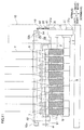
- a linear motion bearing 62 is provided at one end of a supporting member 61 supporting the both ends of the contact roller 11.
- the winder of the modification 2 is provided with a guide shaft 63 which is fixed to an unillustrated frame of the base 10 and extends in the vertical directions.
- the guide shaft 63 is inserted into the linear motion bearing 62.
- 0-rings 64 are provided between the respective ends of the linear motion bearing 62 and the supporting member 61. This allows the supporting member 61 and the contact roller 11 to be swingable with respect to the guide shaft 63 fixed to the base 10.
- a roller 61a At an end of the supporting member 61 is provided a roller 61a. Furthermore, beside the supporting member 61 is provided a tilt mechanism 65 fixed to the unillustrated frame of the base 10, to correspond to the roller 61a.
- the tilt mechanism 65 has a vertically extending groove 66. To this groove 66, the roller 61a of the supporting member 61 is fit. The roller 61a vertically moves along the groove 66 as the supporting member 61 vertically moves along the guide shaft 63. Furthermore, inside the groove 66 is provided a guide member 67 which contacts the leading end portion of the roller 61a. The guide member 67 is tilted with respect to the vertical directions such that the guide surface 67a (guide) contacting the leading end portion of the roller 61a is closer to the supporting member 61 (i.e. is tilted leftward) toward the upper end of the surface.
- the turret table 3 does not rotate when the amount of yarns Y wound onto the bobbins B is increased. Instead, the contact roller 11 and the supporting member 61 are pressed upward by the bobbins B having larger diameters because of the winding of the yarns Y and move along the guide shaft 63, and this increases the distance between the bobbin holder 2 and the contact roller 11.
- the contact roller 11 and the supporting member 61 are pushed and moved upward by the bobbins B and the roller 61a is moved upward along the groove 66 as shown in Fig. 13 .
- the roller 61a is guided along the guide surface 67a of the guide member 67 and hence the supporting member 61 and the contact roller 11 are tilted.
- the contact roller 11 is tilted so that the part corresponding to the leading end side of the bobbin holder 2 is positioned downward.
- the contact roller 11 is equivalent to the moving member of the present invention and the contact roller 11 is mechanically interlocked with the tilt mechanism 65 such that the leading end portion of the roller 61a of the supporting member 61 supporting the contact roller 11 contacts the guide member 67 (guide surface 67a). Furthermore, the tilt mechanism 65 tilts the contact roller 11 by utilizing the movement of the contact roller 11 caused by the increase in the amount of yarns Y wound onto the bobbins B.
- the contact roller 11 may be tilted by another tilt mechanism which is mechanically interlocked with the contact roller 11 and utilizes the movement of the contact roller 11 in a different manner.
- the tilt mechanism tilts the contact roller 11 by utilizing the rotation of the turret table 3 or the movement of the contact roller 11, the present invention is not limited to this.
- the tilt mechanism may be mechanically interlocked with this moving member and tilt the contact roller 11 by utilizing the movement of the moving member.
Landscapes
- Replacing, Conveying, And Pick-Finding For Filamentary Materials (AREA)
- Winding Filamentary Materials (AREA)
Abstract
Description
- The present invention relates to a winder winding yarns onto bobbins.
- The winder of Japanese Unexamined Patent Publication No.
8-310723 - In such a winder, as an amount of yarns wound onto the bobbins by the contact roller increases, the bobbin holder is warped downward toward the leading end which is distanced from the supported part of the bobbin holder, on account of the weight of the yarns.
- In this regard, the winder of Japanese Unexamined Patent Publication No.
8-310723 - However, when as in Japanese Unexamined Patent Publication No.
8-310723 - An object of the present invention is to provide a winder in which improper winding of yarns and the breakdown of portions around the contact roller hardly occur even if a tilt unit by which the contact roller is tilted is broken.
- A winder according to the first aspect of the invention includes: a bobbin holder which is cantilevered at a main body and to which a bobbin for winding yarns is attached; a contact roller which contacts the bobbin attached to the bobbin holder; and a tilt mechanism which tilts the contact roller in a vertical direction, wherein, the tilt mechanism is mechanically interlocked with a moving member which moves in accordance with a change in an amount of the yarns wound onto the bobbin, and the contact roller is tilted by utilizing the movement of the moving member.
- According to the present invention, the tilt mechanism is mechanically interlocked with the moving member which is moved in accordance with a change in the amount of the yarns wound onto the bobbin, and the contact roller is tilted by utilizing the movement of the moving member. For this reason, even if a breakdown occurs, only the mechanical interlocking with the moving member becomes inactive and the tilting of the contact roller by utilizing the movement of the moving member is no longer possible, and hence the tilting angle of the contact roller is not rapidly changed. Therefore the above-described problems such as improper winding of yarns and the vibration of the contact roller hardly occur.
- According to the second aspect of the invention, the winder of the first aspect further includes a turret table which cantilevers the bobbin holder and moves the bobbin holder by rotating about a rotation axis which is in parallel to the axis of the bobbin holder, wherein, when the yarns are wound, the contact roller is maintained at a predetermined position, the turret table functions as the moving member in which the bobbin holder moves away from the contact roller as an amount of the yarns wound onto the bobbin increases, and the tilt mechanism is mechanically interlocked with the turret table and tilts the contact roller by utilizing the rotation of the turret table.
- According to the present invention, during the winding of the yarns, the contact roller is maintained at a predetermined position. Furthermore, when the turret table is arranged to rotate in accordance with the increase in the amount of yarns on the bobbin so as to function as the moving member, the contact roller is tilted by utilizing the rotation of the turret table functioning as the moving member.
- According to the third aspect of the invention, the winder of the second aspect is arranged so that the tilt mechanism tilts the contact roller by transferring the rotation of the turret table to the contact roller and including: a cam which is provided on the turret table and has a cam surface which extends in a direction of the rotation of the turret table; and a cam rod which contacts the cam surface.
- According to the present invention, the contact roller is tilted by transferring the rotation of the turret table to the contact roller via components such as the cam on the turret table and the cam rod on the cam surface.
- According to the fourth aspect of the invention, the winder of any one of the first to third aspects further includes a guide shaft which elevatably supports the contact roller, wherein, the tilt mechanism tilts the contact roller by tilting the guide shaft.
- According to the present invention, when the contact roller is elevatably supported by the guide shaft, the contact roller is tilted by tilting the guide shaft.
- According to the fifth aspect of the invention, the winder of the first aspect is arranged so that the contact roller is arranged to be moved by being pushed by the bobbin to which the yarns are wound, so as to function as the moving member, and the tilt mechanism is mechanically interlocked with the contact roller, and tilts the contact roller by utilizing the movement of the pushed contact roller.
- According to the present invention, during the winding of the yarn, when the contact roller is arranged to be moved by being pushed by the yarn wound onto the bobbin so as to function as the moving member, the contact roller is tilted by utilizing the movement of the contact roller which is the moving member.
- According to the sixth aspect of the invention, the winder of the fifth aspect is arranged so that the tilt mechanism includes a guide member which has a guide being tilted with respect to the vertical direction and tilts the contact roller by guiding the moving contact roller along the guide.
- According to the present invention, the contact roller is tilted by guiding the contact roller, which is moved by being pushed by the yarns wound onto the bobbin, along the guide of the guide member which is tilted in the vertical direction.
- According to the present invention, the tilt mechanism is mechanically interlocked with the moving member which is moved in accordance with a change in the amount of the yarns wound onto the bobbin, and the contact roller is tilted by utilizing the movement of the moving member. For this reason, even if a breakdown occurs, only the mechanical interlocking with the moving member becomes inactive and the tilting of the contact roller by utilizing the movement of the moving member is no longer possible, and hence the tilting angle of the contact roller is not rapidly changed. Therefore the above-described problems such as improper winding of yarns and the vibration of the contact roller hardly occur.
-
-
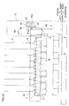
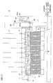
Fig. 1 is an elevation of a winder according to an embodiment of the present invention. -
Fig. 2A shows the winder ofFig. 1 viewed in the direction of the arrow IIA. -
Fig. 2B shows the winder ofFig. 1 viewed in the direction of the arrow IIB. -
Fig. 3A shows the winder ofFig. 1 viewed in the direction of the arrow III. -
Fig. 3B shows the winder ofFig. 3A from which the mounting member and the swing axis are removed. -
Fig. 4 is a cross section taken along the IV-IV line ofFig. 3A . -
Fig. 5A is equivalent toFig. 2A and shows the state during the winding. -
Fig. 5B is equivalent toFig. 2B and shows the state during the winding. -
Fig. 6 is equivalent toFig. 4 and shows the state during the winding. -
Fig. 7 is equivalent toFig. 3B and shows the state during the winding. -
Fig. 8 is equivalent toFig. 1 and shows the state during the winding. -
Fig. 9 relates to a modification 1 and is equivalent toFig. 1 . -
Fig. 10 relates to the modification 1 and is equivalent toFig. 2A . -
Fig. 11 relates to the modification 1 and is equivalent toFig. 8 . -
Fig. 12 relates to amodification 2 and is equivalent toFig. 1 . -
Fig. 13 relates to themodification 2 and is equivalent toFig. 8 . - The following will describe a preferred embodiment of the present invention.
-
Fig. 1 is an elevation of a winder of the present embodiment.Fig. 2A shows the winder ofFig. 1 viewed in the direction of the arrow IIA.Fig. 2B shows the winder ofFig. 1 viewed in the direction of the arrow IIB.Fig. 3A shows the winder ofFig. 1 viewed in the direction of the arrow III.Fig. 3B shows the winder ofFig. 3A from which the mountingmember 22a and theswing axis 36 are removed.Fig. 4 is a cross section taken along the IV-IV line ofFig. 3A . It is noted that, inFig. 1 , a part of abase 10 of the winder 1 is indicated by a two-dot chain line to show the components inside the part indicated by the two-dot chain line. InFig. 3B , the position of the mountingmember 22a is indicated by a two-dot chain line for easily understanding the positional relations of the components. Hereinafter, as indicated in each drawing, the descriptions will be given with reference to front-back directions, crosswise directions, and vertical directions which are orthogonal to one another. - As shown in
Fig. 1 to Fig. 4 , the winder 1 includes components such as abase 10, twobobbin holders 2 attached to thebase 10, a turret table 3, a contact pressure applying mechanism 4, and a tilt mechanism 5. - Each of the two
bobbin holders 2 is a substantially column shaped member cantilevered at the turret table 3. To eachbobbin holder 2, a plurality of substantially cylindrical bobbins B are attached. Eachbobbin holder 2 is rotated about arotation axis 2a by an unillustrated motor, thereby yarns Y are wound onto the bobbins B attached to thebobbin holder 2 as described later. Above the bobbins B attached to thebobbin holders 2, traverseunits 7 are provided. Above eachtraverse unit 7 is provided ayarn guide 8. The yarns Y are therefore wound onto the bobbins B while being traversed on these yarn guides 8 in the crosswise directions by thetraverse units 7. Thetraverse units 7 and the yarn guides 8 are provided on a later-described supportingmember 12, and thesecomponents - The turret table 3 is a substantially circular plate and cantilevers the two
bobbin holders 2 as described above and moves thesebobbin holders 2 as the turret table 3 rotates about arotation axis 3a which is in parallel to the axes of thebobbin holders 2. In the winder 1 arranged as described above, the positions of the twobobbin holders 2 are interchangeable. It is therefore possible to continuously wind yarns in such a way that the bobbins B attached to onebobbin holder 2 are replaced with new ones while yarns are wound onto the bobbins B attached to theother bobbin holder 2. Furthermore, as described later, the turret table 3 rotates during the winding of the yarns Y onto the bobbin B, in accordance with the increase in the amount of wound yarns Y. - The contact pressure applying mechanism 4 includes components such as a
contact roller 11 and a supportingmember 12. Thecontact roller 11 extends substantially in parallel to thebobbin holders 2, and contacts the outer circumference of eachbobbin holder 2 attached to one of the twobobbin holders 2, which is at a winding position. With this, a contact pressure is applied to the bobbins B by thecontact roller 11, when the yarn Y are wound thereon. - The supporting
member 12 rotatably supports the both ends of thecontact roller 11. At around the both ends of the supportingmember 12,linear motion bearings 19 are provided, respectively. Into thelinear motion bearings 19 are inserted vertically-extendingguide shafts 13. The supportingmember 12 is elevatable by an unillustrated elevator mechanism. As the supportingmember 12 is vertically moved, the supportingmember 12 and thecontact roller 11 are also vertically moved along theguide shafts 13. - Each
guide shaft 13 is inserted intolinear motion bearings linear motion bearings members frame 6, respectively. - Each of the
linear motion bearings guide shaft 13. Between the linear motion bearing 21a and theguide shaft 13 inserted thereto, an O-ring 23 is provided. Similarly, between thelinear motion bearing 21b and theguide shaft 13 inserted thereto, an O-ring 23 is provided. With this arrangement, theguide shafts 13 are swingable with respect to thelinear motion bearings members - Now, the arrangement of the tilt mechanism 5 will be described. The tilt mechanism 5 is a mechanism for tilting the
contact roller 11, and includes components such ascams 31, acam rod 32, aforce multiplying arm 33, atie rod 34, and atilt arm 35. - The two
cams 31 are provided on the side face of the turret table 3 to correspond to therespective bobbin holders 2. Eachcam 31 extends along the circumferential direction of the turret table 3 as shown inFig. 2B . The outer circumference of eachcam 31, i.e. thecam surface 31a is arranged to be away from therotation axis 3a of the turret table 3, toward the upstream in the clockwise direction inFig. 2B . - The
cam rod 32 has at its lower end portion aroller 41 which contacts thecam surface 31a, and the upper end portion of thecam rod 32 is connected to theforce multiplying arm 33. Thecam rod 32 further includes arod forming member 32a having theroller 41 and arod forming member 32b connected to theforce multiplying arm 33, and these tworod forming members rod forming member 32a and therod forming member 32b, aspring 42 is provided. As abolt 43 provided immediately above thespring 42 of therod forming member 32b is tightened, thespring 42 is compressed. With this arrangement, to what extent the movement of therod forming member 32a is absorbed by thespring 42 and is transferred to therod forming member 32b is determined by the degree of tightening of thebolt 43. Alternatively, thespring 42 may not be provided. In such a case, a single component substitutes for the tworod forming members cam rod 32. - The
force multiplying arm 33 is a substantially rectangular plate whose one end is attached to thecam rod 32 whereas the other end is attached to aswing axis 36 inserted into abearing 37, so as to be swingable about theswing axis 36. - At the lower end portion of the
swing axis 36, a mountingshaft 38 is attached for mounting thetie rod 34. As such, in theforce multiplying arm 33, thetie rod 34 is mounted to be closer to the center of theswing axis 36 than thecam rod 32. Thetie rod 34 is mounted between theforce multiplying arm 33 and thetilt arm 35 to connect theforce multiplying arm 33 with thetilt arm 35. - The bearing 37 to which the
swing axis 36 is inserted is fixed, in front of thetie rod 34, to a mountingplate 39 which is substantially C-shaped to sandwich thetie rod 34 from the front and rear sides. The mountingplate 39 is fixed to theframe 6 on the side opposite to the side where thebearing 37 is fixed, over thetie rod 34. Also at the portion where theframe 6 is fixed to the mountingplate 39, a swing axis and a bearing similar to theswing axis 36 and thebearing 37 are provided. This swing axis is attached to the end of the mountingshaft 38 which end is opposite to theswing axis 36. - The
tilt arm 35 is a plate extending in the front-back directions, and is swingably supported at its substantially central portion by theswing axis 24 which is provided on the mountingmember 22a. Thetilt arm 35 is attached to thetie rod 34 at the trailing end portion, whereas a throughhole 35a is formed at the leading end portion. To the throughhole 35a is inserted the above-describedguide shaft 13. - Now, the operation to wind the yarns Y in the winder 1 will be described.
Fig. 5 to Fig. 9 show the states during the yarn winding and are equivalent toFig. 2 ,Fig. 4 ,Fig. 3B , andFig. 1 , respectively. - When yarns Y are wound onto the bobbins B in the winder 1, yarns Y produced by an unillustrated spinning apparatus above the winder 1 are placed onto the bobbins B. As the
bobbin holder 2 is rotated in this state, the yarns Y are wound onto the bobbins B while a contact pressure is applied to the bobbins B. - As the winding of the yarns Y onto the bobbins B progresses, the diameter of each bobbin B gradually increases in accordance with the increase in the amount of the wound yarns Y. Taking into consideration of this, it is necessary to gradually increase the distance between the
bobbin holder 2 and thecontact roller 11. - In this state, the supporting
member 12 is not moved (i.e. thecontact roller 11 is retained at a predetermined position) in the present embodiment. As shown inFig. 5A , the distance between thebobbin holder 2 and thecontact roller 11 is gradually increased by rotating the turret table 3 in the direction away from the contact roller 11 (i.e. the anticlockwise direction inFig. 5A and the clockwise direction inFig. 5B ) as the amount of yarns Y wound onto the bobbins B increases. - When the turret table 3 rotates in this way, as shown in
Fig. 5B , thecams 31 on the side wall of the turret table 3 also rotate about therotation axis 3a. As described above, eachcam 31 is arranged so that thecam surface 31a is away from therotation axis 3a of the turret table 3, toward the upstream in the clockwise direction inFig. 2B . For this reason, as eachcam 31 rotates, thecam rod 32 contacting thecam surface 31a of thecam 31 is pushed upward by thecam 31 as indicated by the arrow a. - As the
cam rod 32 moves, as shown inFig. 6 , theforce multiplying arm 33 rotates anticlockwise about theswing axis 36, thereby pulling thetie rod 34 attached to theforce multiplying arm 33 toward the force multiplying arm 33 (i.e. rightward in the figure) as indicated by the arrow b. In this regard, since in theforce multiplying arm 33 thetie rod 34 is attached to be closer to theswing axis 36 than thecam rod 32 as described above, the moving distance of thetie rod 34 in response to the rotation of theforce multiplying arm 33 caused by the movement of thecam rod 32 is shorter than the moving distance of thecam rod 32. Therefore, the force exerted from theforce multiplying arm 33 to thetie rod 34 is greater than the force exerted from thecam rod 32 to theforce multiplying arm 33. - As the
tie rod 34 is pulled toward theforce multiplying arm 33, as shown inFig. 7 , the trailing end portion of thetilt arm 35 connected to thetie rod 34 is also pulled toward theforce multiplying arm 33 as indicated by the arrow b, with the result that thetilt arm 35 rotates clockwise about theswing axis 24. This rotation of thetilt arm 35 causes the leading end portion of thetilt arm 35, to which theguide shaft 13 inserted, to move in the direction (leftward in the figure) opposite to the movement of the trailing end portion, as indicated by the arrow c. - When the leading end portion of the
tilt arm 35 moves in this way, as shown inFig. 6 andFig. 8 , theguide shaft 13 is pressed by the tilt arm 35 (i.e. the wall of the throughhole 35a) and tilted. Therefore the supportingmember 12 elevatable along theguide shaft 13 and thecontact roller 11 supported by the supportingmember 12 are tilted. In this state, thecontact roller 11 is tilted in such a way that the part thereof corresponding to the leading end side of thebobbin holder 2 is positioned downward (inFig. 8 , the tilting angle immediately before the completion of the winding is denoted as α). - In other words, in the present embodiment, the turret table 3 is the moving member of the present invention, and the tilt mechanism 5 constituted by the
cams 31, thecam rod 32, theforce multiplying arm 33,thetie rod 34, and thetilt arm 35 is mechanically interlocked with the turret table 3. The tilt mechanism 5 tilts thecontact roller 11 by using the rotation of the turret table 3 which is the moving member. In addition to the above, as the amount of yarns Y wound onto the bobbins B increases and the degree of the rotation of the turret table 3 increases, the tilting angle of thecontact roller 11 increases. - Now, as the amount of yarns Y wound onto the bobbins B increases, the
bobbin holder 2 is warped downward toward the leading end remote from the part supported by the turret table 3, on account of the weight of the yarns Y. The degree of this warping increases as the amount of yarns Y wound onto the bobbins B increases. Provided that, on the contrary to the arrangement above, thecontact roller 11 is not tilted, the bobbin B attached at the most leading end side of thebobbin holder 2 receives the least contact pressure from thecontact roller 11, with the result that the diameters of the bobbins B are irregular between the left ones and the right ones when the winding of the yarns Y is completed. - In this regard, according to the present embodiment described above, as the amount of yarns Y wound onto the bobbins B increases, the
contact roller 11 is tilted so that the part corresponding to the leading end side of thebobbin holder 2 is positioned downward, with the result that thebobbin holder 2 and thecontact roller 11 are maintained to be more or less in parallel to each other and the distance between them is constant at all parts. The contact pressure between thecontact roller 11 and each bobbin B is therefore constant and the diameter of each bobbin after the winding is constant. - In addition to the above, according to the present embodiment, the tilt mechanism 5 mechanically interlocked with the turret table 3 tilts the
contact roller 11 by transferring, to theguide shaft 13, the rotation of the turret table 3 which rotates in accordance with the increase in the amount of yarns Y wound onto the bobbins B. Because of this arrangement, even if a part of the tilt mechanism 5 is broken, merely the rotation of the turret table 3 is not transferred to the guide shaft 13 (i.e. the tilt mechanism 5 is no longer mechanically interlocked with the turret table 3) and thecontact roller 11 is not tilted any more, and hence thecontact roller 11 is maintained to have the position immediately before the breakdown of the tilt mechanism 5. - For this reason, even if the tilt mechanism 5 is broken, it is possible to restrain problems such as improper winding of yarns Y on the bobbins B on account of a rapid change in the tilting angle of the
contact roller 11 and the breakdown of the part of the supportingmember 12 at which thecontact roller 11 is supported, on account of the vibration of thecontact roller 11. - In addition to the above, the
contact roller 11 has a certain amount of weight and hence a sufficiently large force is required to tilt thecontact roller 11. In this regard since the force applied from theforce multiplying arm 33 to thetie rod 34 is larger than the force applied from thecam rod 32 to theforce multiplying arm 33 as described above, it is possible to tilt theheavy contact roller 11 even if the force by which thecams 31 push thecam rod 32 is not so large. - Now, various modifications of the embodiment will be described. It is noted that the descriptions of the same components as in the embodiment will be suitably omitted.
- While the embodiment above is arranged so that the rotation of the turret table 3 is transferred to the
guide shaft 13 by using the tilt mechanism 5 having thecams 31, thecam rod 32, theforce multiplying arm 33, thetie rod 34, and thetilt arm 35, the rotation of the turret table 3 may be transferred to theguide shaft 13 by using a different mechanism. - In addition to the above, while the embodiment above is arranged so that the supporting
member 12 and thecontact roller 11 are tilted by tilting theguide shaft 13 elevatably supporting the supportingmember 12 supporting thecontact roller 11, thecontact roller 11 may be directly tilted without tilting theguide shaft 13 and the supportingmember 12. - In addition to the above, the embodiment above is arranged so that, since the supporting
member 12 supporting thecontact roller 11 is elevatable, thecontact roller 11 is caused to contact the bobbins B when the yarns Y are wound whereas thecontact roller 11 is moved away from thebobbin holder 2 in cases such as the placement of the yarns. In this regard, a different structure may be used for moving thecontact roller 11 to contact or to be away from thebobbin holder 2. - According to a modification (modification 1), as shown in
Fig. 9 andFig. 10 , the supportingmember 51 supporting thecontact roller 11 is provided with aswing axis 52. The respective ends of theswing axis 52 are inserted intobearings member 51 to be swingable about theswing axis 52. By swinging the supportingmember 51, thecontact roller 11 is moved between the position which is indicated by the full line inFig. 10 and where thecontact roller 11 contacts the bobbins B and the position which is indicated by the two-dot chain line inFig. 10 and where thecontact roller 11 is away from thebobbin holder 2. - The
bearings swing axis 52 is arranged to be swingable with respect to thebearings - The
bearing 53a is attached to an unillustrated frame or the like which is fixed to thebase 10, whereas thebearing 53b is attached to thearm 54. Thearm 54 is supported to be swingable about aswing axis 55 at an end thereof. Thisarm 54 is provided with the bearing 53b substantially at the center thereof, and is connected to thecam rod 32 at the end opposite to theswing axis 55. In other words, thearm 54 is arranged so that thebearing 53b is closer to theswing axis 55 than thecam rod 32. - Also in this case, in the same manner as the embodiment above, the turret table 3 rotates as the amount of yarns Y wound onto the bobbins B increases, wit the result that the
cams 31 rotate and thecam rod 32 is pressed by thecams 31 and moved upward. In the modification 1, however, as thecam rod 32 is moved upward, as shown inFig. 11 , thearm 54 is swung about theswing axis 55 and thebearing 53b attached to thearm 54 is pushed upward. This tilts theswing axis 52 which is inserted into thebearings member 51 supported by theswing axis 52, and thecontact roller 11 supported by the supportingmember 51. Also in this case, thecontact roller 11 is tilted so that the part corresponding to the leading end side of thebobbin holder 2 is positioned downward. In the modification 1, thecams 31, thecam rod 32, and thearm 54 for tilting thecontact roller 11 are the tilt mechanism of the present invention. - Also in the modification 1, in the
arm 54 thebearing 53b is attached to be closer to theswing axis 55 than thecam rod 32, and hence the moving distance of the bearing 53b in response to the rotation of thearm 54 is shorter than the moving distance of thecam rod 32. Therefore the force applied from thearm 54 to thebearing 53b is larger than the force applied from thecam rod 32 to thearm 54, and hence theheavy contact roller 11 is tilted even if the force by which thecams 31 push thecam rod 32 is not so large. - Furthermore, the embodiment above is arranged so that the distance between the
bobbin holder 2 and thecontact roller 11 is gradually increased by rotating the turret table 3 in accordance with the increase in the amount of yarns Y wound onto the bobbins B, and thecontact roller 11 is tilted by transferring the rotation of the turret table 3 thereto. The present invention, however, is not limited to this arrangement. - According to another modification (modification 2), as shown in
Fig. 12 , a linear motion bearing 62 is provided at one end of a supportingmember 61 supporting the both ends of thecontact roller 11. The winder of themodification 2 is provided with aguide shaft 63 which is fixed to an unillustrated frame of thebase 10 and extends in the vertical directions. Theguide shaft 63 is inserted into thelinear motion bearing 62. With this arrangement, the supportingmember 61 and thecontact roller 11 are supported by theguide shaft 63 and are arranged to be elevatable along theguide shaft 63. - In connection with the above, 0-
rings 64 are provided between the respective ends of the linear motion bearing 62 and the supportingmember 61. This allows the supportingmember 61 and thecontact roller 11 to be swingable with respect to theguide shaft 63 fixed to thebase 10. - In addition to the above, at an end of the supporting
member 61 is provided aroller 61a. Furthermore, beside the supportingmember 61 is provided atilt mechanism 65 fixed to the unillustrated frame of thebase 10, to correspond to theroller 61a. - The
tilt mechanism 65 has a vertically extendinggroove 66. To thisgroove 66, theroller 61a of the supportingmember 61 is fit. Theroller 61a vertically moves along thegroove 66 as the supportingmember 61 vertically moves along theguide shaft 63. Furthermore, inside thegroove 66 is provided aguide member 67 which contacts the leading end portion of theroller 61a. Theguide member 67 is tilted with respect to the vertical directions such that theguide surface 67a (guide) contacting the leading end portion of theroller 61a is closer to the supporting member 61 (i.e. is tilted leftward) toward the upper end of the surface. - In this case, the turret table 3 does not rotate when the amount of yarns Y wound onto the bobbins B is increased. Instead, the
contact roller 11 and the supportingmember 61 are pressed upward by the bobbins B having larger diameters because of the winding of the yarns Y and move along theguide shaft 63, and this increases the distance between thebobbin holder 2 and thecontact roller 11. - As the amount of yarns Y wound onto the bobbins B is increased, the
contact roller 11 and the supportingmember 61 are pushed and moved upward by the bobbins B and theroller 61a is moved upward along thegroove 66 as shown inFig. 13 . As a result, theroller 61a is guided along theguide surface 67a of theguide member 67 and hence the supportingmember 61 and thecontact roller 11 are tilted. Also in this case, thecontact roller 11 is tilted so that the part corresponding to the leading end side of thebobbin holder 2 is positioned downward. - That is to say, in the
modification 2, thecontact roller 11 is equivalent to the moving member of the present invention and thecontact roller 11 is mechanically interlocked with thetilt mechanism 65 such that the leading end portion of theroller 61a of the supportingmember 61 supporting thecontact roller 11 contacts the guide member 67 (guidesurface 67a). Furthermore, thetilt mechanism 65 tilts thecontact roller 11 by utilizing the movement of thecontact roller 11 caused by the increase in the amount of yarns Y wound onto the bobbins B. - In addition to the above, while the
modification 2 is arranged so that thecontact roller 11 is tilted by guiding the supportingmember 61 along theguide surface 67a of theguide member 67, thecontact roller 11 may be tilted by another tilt mechanism which is mechanically interlocked with thecontact roller 11 and utilizes the movement of thecontact roller 11 in a different manner. - In addition to the above, while in the arrangement above the tilt mechanism tilts the
contact roller 11 by utilizing the rotation of the turret table 3 or the movement of thecontact roller 11, the present invention is not limited to this. For example, when the winder includes a moving member which moves in accordance with the increase in the amount of yarns Y on the bobbins B and is different from the turret table 3 and thecontact roller 11, the tilt mechanism may be mechanically interlocked with this moving member and tilt thecontact roller 11 by utilizing the movement of the moving member. The features of the dependent claims as well as all features of preferred embodiments mentioned above can be combined with each other as long as they do not contradict each other.
Claims (6)
- A winder comprising:a bobbin holder which is cantilevered at a main body and to which a bobbin for winding yarns is attached;a contact roller which contacts the bobbin attached to the bobbin holder; anda tilt mechanism which tilts the contact roller in a vertical direction, wherein,the tilt mechanism is mechanically interlocked with a moving member which moves in accordance with a change in an amount of the yarns wound onto the bobbin, and the contact roller is tilted by utilizing the movement of the moving member.
- The winder according to claim 1, further comprising:a turret table which cantilevers the bobbin holder and moves the bobbin holder by rotating about a rotation axis which is in parallel to the axis of the bobbin holder, wherein,when the yarns are wound,the contact roller is maintained at a predetermined position,the turret table functions as the moving member in which the bobbin holder moves away from the contact roller as an amount of the yarns wound onto the bobbin increases, andthe tilt mechanism is mechanically interlocked with the turret table and tilts the contact roller by utilizing the rotation of the turret table.
- The winder according to claim 2, wherein,
the tilt mechanism tilts the contact roller by transferring the rotation of the turret table to the contact roller and including:a cam which is provided on the turret table and has a cam surface which extends in a direction of the rotation of the turret table; anda cam rod which contacts the cam surface. - The winder according to any one of claims 1 to 3, further comprising:a guide shaft which elevatably supports the contact roller, wherein,the tilt mechanism tilts the contact roller by tilting the guide shaft.
- The winder according to claim 1, wherein,
the contact roller is arranged to be moved by being pushed by the bobbin to which the yarns are wound, so as to function as the moving member, and
the tilt mechanism is mechanically interlocked with the contact roller, and tilts the contact roller by utilizing the movement of the pushed contact roller. - The winder according to claim 5, wherein,
the tilt mechanism includes a guide member which has a guide being tilted with respect to the vertical direction and tilts the contact roller by guiding the moving contact roller along the guide.
Applications Claiming Priority (1)
| Application Number | Priority Date | Filing Date | Title |
|---|---|---|---|
| JP2010129624A JP5529632B2 (en) | 2010-06-07 | 2010-06-07 | Winder |
Publications (3)
| Publication Number | Publication Date |
|---|---|
| EP2392532A2 true EP2392532A2 (en) | 2011-12-07 |
| EP2392532A3 EP2392532A3 (en) | 2013-02-20 |
| EP2392532B1 EP2392532B1 (en) | 2014-03-05 |
Family
ID=44312319
Family Applications (1)
| Application Number | Title | Priority Date | Filing Date |
|---|---|---|---|
| EP20110166875 Active EP2392532B1 (en) | 2010-06-07 | 2011-05-20 | Winder |
Country Status (3)
| Country | Link |
|---|---|
| EP (1) | EP2392532B1 (en) |
| JP (1) | JP5529632B2 (en) |
| CN (1) | CN102267652B (en) |
Cited By (5)
| Publication number | Priority date | Publication date | Assignee | Title |
|---|---|---|---|---|
| EP3357847A1 (en) * | 2017-02-06 | 2018-08-08 | TMT Machinery, Inc. | Yarn winder, spun yarn take-up apparatus, and a method of yarn threading in yarn winder |
| EP3412611A1 (en) * | 2017-06-06 | 2018-12-12 | TMT Machinery, Inc. | Yarn winder |
| WO2020126724A1 (en) | 2018-12-19 | 2020-06-25 | Oerlikon Textile Gmbh & Co. Kg | Winding machine |
| EP4349753A3 (en) * | 2020-11-27 | 2024-06-26 | TMT Machinery, Inc. | Yarn winder |
| EP4717646A1 (en) * | 2024-09-30 | 2026-04-01 | TMT Machinery, Inc. | Yarn winder |
Families Citing this family (10)
| Publication number | Priority date | Publication date | Assignee | Title |
|---|---|---|---|---|
| JP5860348B2 (en) * | 2012-06-19 | 2016-02-16 | Tmtマシナリー株式会社 | Spinning winder |
| CN102774703B (en) * | 2012-07-31 | 2013-08-14 | 太仓仕禾线网制造有限公司 | Yarn winding device for silk winder |
| CN102774704B (en) * | 2012-07-31 | 2014-04-16 | 太仓仕禾线网制造有限公司 | Yarn coiling device of winder |
| JP6275972B2 (en) * | 2013-08-23 | 2018-02-07 | Tmtマシナリー株式会社 | Textile machinery |
| JP6512950B2 (en) * | 2014-07-02 | 2019-05-15 | Tmtマシナリー株式会社 | Yarn winding device and spinning take-off device |
| CN104401809B (en) * | 2014-11-03 | 2015-07-29 | 江苏银桥纺织科技有限公司 | A kind of weaving wire coiling machine and method of operation thereof being convenient to loaded line cylinder |
| CN104401799B (en) * | 2014-11-03 | 2016-06-15 | 重庆晨宇机床制造有限公司 | A kind of fixed weaving coil winding machine being easy to load spool |
| CN104444601A (en) * | 2014-11-03 | 2015-03-25 | 宁波海曙信满贸易有限公司 | Spinning winding machine allowing bobbins to be conveniently loaded and easy to maintain |
| CN104444575A (en) * | 2014-11-03 | 2015-03-25 | 洪恒丰 | Spinning winding machine allowing bobbins to be conveniently loaded and capable of being automatically tensioned |
| DE102023001454A1 (en) | 2023-04-14 | 2024-10-17 | Oerlikon Textile Gmbh & Co. Kg | Device for compensating a load bending line of a winding spindle |
Citations (1)
| Publication number | Priority date | Publication date | Assignee | Title |
|---|---|---|---|---|
| JPH08310723A (en) | 1995-05-17 | 1996-11-26 | Murata Mach Ltd | Winder |
Family Cites Families (6)
| Publication number | Priority date | Publication date | Assignee | Title |
|---|---|---|---|---|
| JPS5255746A (en) * | 1975-10-30 | 1977-05-07 | Mitsubishi Heavy Ind Ltd | Build up process of high speed winder driving roll |
| BR8008752A (en) * | 1979-07-10 | 1981-05-26 | Rieter Ag Maschf | WINDING EQUIPMENT FOR WIRES OR FILAMENTS |
| JPS61273471A (en) * | 1985-05-24 | 1986-12-03 | Mitsubishi Heavy Ind Ltd | High speed thread winding machine |
| JPH0346969A (en) * | 1989-07-14 | 1991-02-28 | Murata Mach Ltd | Spinning take-up machine |
| CH694370A5 (en) * | 1999-02-03 | 2004-12-15 | Barmag Barmer Maschf | Winder. |
| US6622956B2 (en) * | 2000-11-08 | 2003-09-23 | Murata Kikai Kabushiki Kaisha | Take-up winder |
-
2010
- 2010-06-07 JP JP2010129624A patent/JP5529632B2/en active Active
-
2011
- 2011-05-20 EP EP20110166875 patent/EP2392532B1/en active Active
- 2011-05-27 CN CN201110139813.5A patent/CN102267652B/en active Active
Patent Citations (1)
| Publication number | Priority date | Publication date | Assignee | Title |
|---|---|---|---|---|
| JPH08310723A (en) | 1995-05-17 | 1996-11-26 | Murata Mach Ltd | Winder |
Cited By (6)
| Publication number | Priority date | Publication date | Assignee | Title |
|---|---|---|---|---|
| EP3357847A1 (en) * | 2017-02-06 | 2018-08-08 | TMT Machinery, Inc. | Yarn winder, spun yarn take-up apparatus, and a method of yarn threading in yarn winder |
| EP3412611A1 (en) * | 2017-06-06 | 2018-12-12 | TMT Machinery, Inc. | Yarn winder |
| WO2020126724A1 (en) | 2018-12-19 | 2020-06-25 | Oerlikon Textile Gmbh & Co. Kg | Winding machine |
| CN113195390A (en) * | 2018-12-19 | 2021-07-30 | 欧瑞康纺织有限及两合公司 | Winding machine |
| EP4349753A3 (en) * | 2020-11-27 | 2024-06-26 | TMT Machinery, Inc. | Yarn winder |
| EP4717646A1 (en) * | 2024-09-30 | 2026-04-01 | TMT Machinery, Inc. | Yarn winder |
Also Published As
| Publication number | Publication date |
|---|---|
| EP2392532A3 (en) | 2013-02-20 |
| JP2011255979A (en) | 2011-12-22 |
| CN102267652B (en) | 2015-07-15 |
| CN102267652A (en) | 2011-12-07 |
| JP5529632B2 (en) | 2014-06-25 |
| EP2392532B1 (en) | 2014-03-05 |
Similar Documents
| Publication | Publication Date | Title |
|---|---|---|
| EP2392532B1 (en) | Winder | |
| EP2497732B1 (en) | Spinning winder | |
| CN100404401C (en) | traverse device | |
| EP2423143B1 (en) | Use of a yarn winding device | |
| JP4990681B2 (en) | Yarn winding machine | |
| EP2548830A2 (en) | Spinning winder | |
| CN101439817A (en) | Double-drum winding machine | |
| TWI790374B (en) | Wire Winder | |
| JP2012158436A (en) | Yarn winder | |
| KR101898760B1 (en) | Bead ring winding device | |
| JP2002145527A (en) | Winder for particularly sensitive winding materials | |
| JP3868251B2 (en) | Winding tube feeder for textile machine work place manufacturing twill package | |
| CN109732016B (en) | Spring winding device | |
| RU2392214C1 (en) | Pickup of winding machine | |
| JP6116372B2 (en) | Winding device having locking means for package frame | |
| WO2020031457A1 (en) | Yarn winder | |
| EP3118148B1 (en) | Yarn winding device | |
| JP2014136619A (en) | Metal wire let-off device | |
| EP3006384B1 (en) | Bobbin separating device, doffing cart, and yarn winding machine | |
| CN113195390B (en) | Winding machine | |
| JP3269327B2 (en) | Winder | |
| JP2714032B2 (en) | Optical fiber feeding device | |
| CN223587611U (en) | A swing arm type V-support mechanism | |
| JP4116751B2 (en) | Wire supply member, wire winding method and apparatus | |
| CN216632176U (en) | Automatic pre-winding machine for steel drum |
Legal Events
| Date | Code | Title | Description |
|---|---|---|---|
| AK | Designated contracting states |
Kind code of ref document: A2 Designated state(s): AL AT BE BG CH CY CZ DE DK EE ES FI FR GB GR HR HU IE IS IT LI LT LU LV MC MK MT NL NO PL PT RO RS SE SI SK SM TR |
|
| AX | Request for extension of the european patent |
Extension state: BA ME |
|
| PUAI | Public reference made under article 153(3) epc to a published international application that has entered the european phase |
Free format text: ORIGINAL CODE: 0009012 |
|
| PUAL | Search report despatched |
Free format text: ORIGINAL CODE: 0009013 |
|
| AK | Designated contracting states |
Kind code of ref document: A3 Designated state(s): AL AT BE BG CH CY CZ DE DK EE ES FI FR GB GR HR HU IE IS IT LI LT LU LV MC MK MT NL NO PL PT RO RS SE SI SK SM TR |
|
| AX | Request for extension of the european patent |
Extension state: BA ME |
|
| RIC1 | Information provided on ipc code assigned before grant |
Ipc: B65H 54/52 20060101AFI20130111BHEP Ipc: B65H 67/048 20060101ALI20130111BHEP |
|
| 17P | Request for examination filed |
Effective date: 20130523 |
|
| RBV | Designated contracting states (corrected) |
Designated state(s): AL AT BE BG CH CY CZ DE DK EE ES FI FR GB GR HR HU IE IS IT LI LT LU LV MC MK MT NL NO PL PT RO RS SE SI SK SM TR |
|
| GRAP | Despatch of communication of intention to grant a patent |
Free format text: ORIGINAL CODE: EPIDOSNIGR1 |
|
| INTG | Intention to grant announced |
Effective date: 20131001 |
|
| GRAS | Grant fee paid |
Free format text: ORIGINAL CODE: EPIDOSNIGR3 |
|
| GRAA | (expected) grant |
Free format text: ORIGINAL CODE: 0009210 |
|
| AK | Designated contracting states |
Kind code of ref document: B1 Designated state(s): AL AT BE BG CH CY CZ DE DK EE ES FI FR GB GR HR HU IE IS IT LI LT LU LV MC MK MT NL NO PL PT RO RS SE SI SK SM TR |
|
| REG | Reference to a national code |
Ref country code: GB Ref legal event code: FG4D |
|
| REG | Reference to a national code |
Ref country code: CH Ref legal event code: EP |
|
| REG | Reference to a national code |
Ref country code: AT Ref legal event code: REF Ref document number: 654722 Country of ref document: AT Kind code of ref document: T Effective date: 20140315 |
|
| RIN2 | Information on inventor provided after grant (corrected) |
Inventor name: SUGIYAMA, KENJI |
|
| REG | Reference to a national code |
Ref country code: IE Ref legal event code: FG4D |
|
| REG | Reference to a national code |
Ref country code: DE Ref legal event code: R096 Ref document number: 602011005163 Country of ref document: DE Effective date: 20140417 |
|
| RIN2 | Information on inventor provided after grant (corrected) |
Inventor name: SUGIYAMA, KENJI |
|
| REG | Reference to a national code |
Ref country code: AT Ref legal event code: MK05 Ref document number: 654722 Country of ref document: AT Kind code of ref document: T Effective date: 20140305 |
|
| REG | Reference to a national code |
Ref country code: NL Ref legal event code: VDEP Effective date: 20140305 |
|
| PG25 | Lapsed in a contracting state [announced via postgrant information from national office to epo] |
Ref country code: LT Free format text: LAPSE BECAUSE OF FAILURE TO SUBMIT A TRANSLATION OF THE DESCRIPTION OR TO PAY THE FEE WITHIN THE PRESCRIBED TIME-LIMIT Effective date: 20140305 Ref country code: NO Free format text: LAPSE BECAUSE OF FAILURE TO SUBMIT A TRANSLATION OF THE DESCRIPTION OR TO PAY THE FEE WITHIN THE PRESCRIBED TIME-LIMIT Effective date: 20140605 |
|
| REG | Reference to a national code |
Ref country code: LT Ref legal event code: MG4D |
|
| PG25 | Lapsed in a contracting state [announced via postgrant information from national office to epo] |
Ref country code: AT Free format text: LAPSE BECAUSE OF FAILURE TO SUBMIT A TRANSLATION OF THE DESCRIPTION OR TO PAY THE FEE WITHIN THE PRESCRIBED TIME-LIMIT Effective date: 20140305 Ref country code: FI Free format text: LAPSE BECAUSE OF FAILURE TO SUBMIT A TRANSLATION OF THE DESCRIPTION OR TO PAY THE FEE WITHIN THE PRESCRIBED TIME-LIMIT Effective date: 20140305 Ref country code: CY Free format text: LAPSE BECAUSE OF FAILURE TO SUBMIT A TRANSLATION OF THE DESCRIPTION OR TO PAY THE FEE WITHIN THE PRESCRIBED TIME-LIMIT Effective date: 20140305 Ref country code: SE Free format text: LAPSE BECAUSE OF FAILURE TO SUBMIT A TRANSLATION OF THE DESCRIPTION OR TO PAY THE FEE WITHIN THE PRESCRIBED TIME-LIMIT Effective date: 20140305 |
|
| PG25 | Lapsed in a contracting state [announced via postgrant information from national office to epo] |
Ref country code: HR Free format text: LAPSE BECAUSE OF FAILURE TO SUBMIT A TRANSLATION OF THE DESCRIPTION OR TO PAY THE FEE WITHIN THE PRESCRIBED TIME-LIMIT Effective date: 20140305 Ref country code: RS Free format text: LAPSE BECAUSE OF FAILURE TO SUBMIT A TRANSLATION OF THE DESCRIPTION OR TO PAY THE FEE WITHIN THE PRESCRIBED TIME-LIMIT Effective date: 20140305 Ref country code: LV Free format text: LAPSE BECAUSE OF FAILURE TO SUBMIT A TRANSLATION OF THE DESCRIPTION OR TO PAY THE FEE WITHIN THE PRESCRIBED TIME-LIMIT Effective date: 20140305 |
|
| PG25 | Lapsed in a contracting state [announced via postgrant information from national office to epo] |
Ref country code: EE Free format text: LAPSE BECAUSE OF FAILURE TO SUBMIT A TRANSLATION OF THE DESCRIPTION OR TO PAY THE FEE WITHIN THE PRESCRIBED TIME-LIMIT Effective date: 20140305 Ref country code: CZ Free format text: LAPSE BECAUSE OF FAILURE TO SUBMIT A TRANSLATION OF THE DESCRIPTION OR TO PAY THE FEE WITHIN THE PRESCRIBED TIME-LIMIT Effective date: 20140305 Ref country code: BG Free format text: LAPSE BECAUSE OF FAILURE TO SUBMIT A TRANSLATION OF THE DESCRIPTION OR TO PAY THE FEE WITHIN THE PRESCRIBED TIME-LIMIT Effective date: 20140605 Ref country code: IS Free format text: LAPSE BECAUSE OF FAILURE TO SUBMIT A TRANSLATION OF THE DESCRIPTION OR TO PAY THE FEE WITHIN THE PRESCRIBED TIME-LIMIT Effective date: 20140705 Ref country code: NL Free format text: LAPSE BECAUSE OF FAILURE TO SUBMIT A TRANSLATION OF THE DESCRIPTION OR TO PAY THE FEE WITHIN THE PRESCRIBED TIME-LIMIT Effective date: 20140305 Ref country code: BE Free format text: LAPSE BECAUSE OF FAILURE TO SUBMIT A TRANSLATION OF THE DESCRIPTION OR TO PAY THE FEE WITHIN THE PRESCRIBED TIME-LIMIT Effective date: 20140305 Ref country code: RO Free format text: LAPSE BECAUSE OF FAILURE TO SUBMIT A TRANSLATION OF THE DESCRIPTION OR TO PAY THE FEE WITHIN THE PRESCRIBED TIME-LIMIT Effective date: 20140305 |
|
| PG25 | Lapsed in a contracting state [announced via postgrant information from national office to epo] |
Ref country code: PL Free format text: LAPSE BECAUSE OF FAILURE TO SUBMIT A TRANSLATION OF THE DESCRIPTION OR TO PAY THE FEE WITHIN THE PRESCRIBED TIME-LIMIT Effective date: 20140305 Ref country code: SK Free format text: LAPSE BECAUSE OF FAILURE TO SUBMIT A TRANSLATION OF THE DESCRIPTION OR TO PAY THE FEE WITHIN THE PRESCRIBED TIME-LIMIT Effective date: 20140305 Ref country code: ES Free format text: LAPSE BECAUSE OF FAILURE TO SUBMIT A TRANSLATION OF THE DESCRIPTION OR TO PAY THE FEE WITHIN THE PRESCRIBED TIME-LIMIT Effective date: 20140305 |
|
| REG | Reference to a national code |
Ref country code: DE Ref legal event code: R097 Ref document number: 602011005163 Country of ref document: DE |
|
| PG25 | Lapsed in a contracting state [announced via postgrant information from national office to epo] |
Ref country code: LU Free format text: LAPSE BECAUSE OF FAILURE TO SUBMIT A TRANSLATION OF THE DESCRIPTION OR TO PAY THE FEE WITHIN THE PRESCRIBED TIME-LIMIT Effective date: 20140520 Ref country code: PT Free format text: LAPSE BECAUSE OF FAILURE TO SUBMIT A TRANSLATION OF THE DESCRIPTION OR TO PAY THE FEE WITHIN THE PRESCRIBED TIME-LIMIT Effective date: 20140707 |
|
| REG | Reference to a national code |
Ref country code: CH Ref legal event code: PL |
|
| PLBE | No opposition filed within time limit |
Free format text: ORIGINAL CODE: 0009261 |
|
| STAA | Information on the status of an ep patent application or granted ep patent |
Free format text: STATUS: NO OPPOSITION FILED WITHIN TIME LIMIT |
|
| PG25 | Lapsed in a contracting state [announced via postgrant information from national office to epo] |
Ref country code: LI Free format text: LAPSE BECAUSE OF NON-PAYMENT OF DUE FEES Effective date: 20140531 Ref country code: MC Free format text: LAPSE BECAUSE OF FAILURE TO SUBMIT A TRANSLATION OF THE DESCRIPTION OR TO PAY THE FEE WITHIN THE PRESCRIBED TIME-LIMIT Effective date: 20140305 Ref country code: DK Free format text: LAPSE BECAUSE OF FAILURE TO SUBMIT A TRANSLATION OF THE DESCRIPTION OR TO PAY THE FEE WITHIN THE PRESCRIBED TIME-LIMIT Effective date: 20140305 Ref country code: CH Free format text: LAPSE BECAUSE OF NON-PAYMENT OF DUE FEES Effective date: 20140531 |
|
| 26N | No opposition filed |
Effective date: 20141208 |
|
| REG | Reference to a national code |
Ref country code: IE Ref legal event code: MM4A |
|
| REG | Reference to a national code |
Ref country code: FR Ref legal event code: ST Effective date: 20150130 |
|
| REG | Reference to a national code |
Ref country code: DE Ref legal event code: R097 Ref document number: 602011005163 Country of ref document: DE Effective date: 20141208 |
|
| PG25 | Lapsed in a contracting state [announced via postgrant information from national office to epo] |
Ref country code: IT Free format text: LAPSE BECAUSE OF FAILURE TO SUBMIT A TRANSLATION OF THE DESCRIPTION OR TO PAY THE FEE WITHIN THE PRESCRIBED TIME-LIMIT Effective date: 20140305 |
|
| PG25 | Lapsed in a contracting state [announced via postgrant information from national office to epo] |
Ref country code: IE Free format text: LAPSE BECAUSE OF NON-PAYMENT OF DUE FEES Effective date: 20140520 |
|
| PG25 | Lapsed in a contracting state [announced via postgrant information from national office to epo] |
Ref country code: SI Free format text: LAPSE BECAUSE OF FAILURE TO SUBMIT A TRANSLATION OF THE DESCRIPTION OR TO PAY THE FEE WITHIN THE PRESCRIBED TIME-LIMIT Effective date: 20140305 Ref country code: FR Free format text: LAPSE BECAUSE OF NON-PAYMENT OF DUE FEES Effective date: 20140602 |
|
| GBPC | Gb: european patent ceased through non-payment of renewal fee |
Effective date: 20150520 |
|
| PG25 | Lapsed in a contracting state [announced via postgrant information from national office to epo] |
Ref country code: MT Free format text: LAPSE BECAUSE OF FAILURE TO SUBMIT A TRANSLATION OF THE DESCRIPTION OR TO PAY THE FEE WITHIN THE PRESCRIBED TIME-LIMIT Effective date: 20140305 |
|
| PG25 | Lapsed in a contracting state [announced via postgrant information from national office to epo] |
Ref country code: GB Free format text: LAPSE BECAUSE OF NON-PAYMENT OF DUE FEES Effective date: 20150520 Ref country code: SM Free format text: LAPSE BECAUSE OF FAILURE TO SUBMIT A TRANSLATION OF THE DESCRIPTION OR TO PAY THE FEE WITHIN THE PRESCRIBED TIME-LIMIT Effective date: 20140305 |
|
| PG25 | Lapsed in a contracting state [announced via postgrant information from national office to epo] |
Ref country code: GR Free format text: LAPSE BECAUSE OF FAILURE TO SUBMIT A TRANSLATION OF THE DESCRIPTION OR TO PAY THE FEE WITHIN THE PRESCRIBED TIME-LIMIT Effective date: 20140606 |
|
| PG25 | Lapsed in a contracting state [announced via postgrant information from national office to epo] |
Ref country code: HU Free format text: LAPSE BECAUSE OF FAILURE TO SUBMIT A TRANSLATION OF THE DESCRIPTION OR TO PAY THE FEE WITHIN THE PRESCRIBED TIME-LIMIT; INVALID AB INITIO Effective date: 20110520 Ref country code: TR Free format text: LAPSE BECAUSE OF FAILURE TO SUBMIT A TRANSLATION OF THE DESCRIPTION OR TO PAY THE FEE WITHIN THE PRESCRIBED TIME-LIMIT Effective date: 20140305 |
|
| PG25 | Lapsed in a contracting state [announced via postgrant information from national office to epo] |
Ref country code: MK Free format text: LAPSE BECAUSE OF FAILURE TO SUBMIT A TRANSLATION OF THE DESCRIPTION OR TO PAY THE FEE WITHIN THE PRESCRIBED TIME-LIMIT Effective date: 20140305 |
|
| PG25 | Lapsed in a contracting state [announced via postgrant information from national office to epo] |
Ref country code: AL Free format text: LAPSE BECAUSE OF FAILURE TO SUBMIT A TRANSLATION OF THE DESCRIPTION OR TO PAY THE FEE WITHIN THE PRESCRIBED TIME-LIMIT Effective date: 20140305 |
|
| P01 | Opt-out of the competence of the unified patent court (upc) registered |
Effective date: 20230426 |
|
| PGFP | Annual fee paid to national office [announced via postgrant information from national office to epo] |
Ref country code: DE Payment date: 20260528 Year of fee payment: 16 |