EP2392185B1 - Transceiver device for on-body and off-body communications - Google Patents
Transceiver device for on-body and off-body communications Download PDFInfo
- Publication number
- EP2392185B1 EP2392185B1 EP10703516.4A EP10703516A EP2392185B1 EP 2392185 B1 EP2392185 B1 EP 2392185B1 EP 10703516 A EP10703516 A EP 10703516A EP 2392185 B1 EP2392185 B1 EP 2392185B1
- Authority
- EP
- European Patent Office
- Prior art keywords
- communications
- transceiver device
- antenna system
- data
- transceiver
- Prior art date
- Legal status (The legal status is an assumption and is not a legal conclusion. Google has not performed a legal analysis and makes no representation as to the accuracy of the status listed.)
- Active
Links
- 238000004891 communication Methods 0.000 title claims description 129
- 238000010586 diagram Methods 0.000 claims description 32
- 238000000034 method Methods 0.000 claims description 30
- 108700026140 MAC combination Proteins 0.000 claims description 12
- 230000005540 biological transmission Effects 0.000 claims description 12
- 238000012545 processing Methods 0.000 claims description 2
- 230000008569 process Effects 0.000 description 15
- 230000006870 function Effects 0.000 description 6
- 229920008347 Cellulose acetate propionate Polymers 0.000 description 4
- 238000009470 controlled atmosphere packaging Methods 0.000 description 4
- 230000009467 reduction Effects 0.000 description 4
- 238000005265 energy consumption Methods 0.000 description 3
- 230000010363 phase shift Effects 0.000 description 3
- 101150018112 GTS1 gene Proteins 0.000 description 2
- 230000036772 blood pressure Effects 0.000 description 2
- 230000008859 change Effects 0.000 description 2
- 238000004590 computer program Methods 0.000 description 2
- 230000001276 controlling effect Effects 0.000 description 2
- 230000000694 effects Effects 0.000 description 2
- 238000002565 electrocardiography Methods 0.000 description 2
- 230000036541 health Effects 0.000 description 2
- 230000001788 irregular Effects 0.000 description 2
- 230000035515 penetration Effects 0.000 description 2
- 230000005855 radiation Effects 0.000 description 2
- 101100172132 Mus musculus Eif3a gene Proteins 0.000 description 1
- 239000000853 adhesive Substances 0.000 description 1
- 230000001070 adhesive effect Effects 0.000 description 1
- 230000002411 adverse Effects 0.000 description 1
- 230000006399 behavior Effects 0.000 description 1
- 238000006243 chemical reaction Methods 0.000 description 1
- 239000004020 conductor Substances 0.000 description 1
- 230000003111 delayed effect Effects 0.000 description 1
- 230000007613 environmental effect Effects 0.000 description 1
- 230000002452 interceptive effect Effects 0.000 description 1
- 238000005259 measurement Methods 0.000 description 1
- 238000012544 monitoring process Methods 0.000 description 1
- 230000005404 monopole Effects 0.000 description 1
- 230000003287 optical effect Effects 0.000 description 1
- 230000010287 polarization Effects 0.000 description 1
- 230000001105 regulatory effect Effects 0.000 description 1
- 239000004065 semiconductor Substances 0.000 description 1
- 230000001360 synchronised effect Effects 0.000 description 1
- 238000012546 transfer Methods 0.000 description 1
Images


Classifications
-
- H—ELECTRICITY
- H04—ELECTRIC COMMUNICATION TECHNIQUE
- H04W—WIRELESS COMMUNICATION NETWORKS
- H04W72/00—Local resource management
- H04W72/12—Wireless traffic scheduling
- H04W72/1215—Wireless traffic scheduling for collaboration of different radio technologies
-
- H—ELECTRICITY
- H04—ELECTRIC COMMUNICATION TECHNIQUE
- H04W—WIRELESS COMMUNICATION NETWORKS
- H04W84/00—Network topologies
- H04W84/02—Hierarchically pre-organised networks, e.g. paging networks, cellular networks, WLAN [Wireless Local Area Network] or WLL [Wireless Local Loop]
- H04W84/10—Small scale networks; Flat hierarchical networks
-
- H—ELECTRICITY
- H04—ELECTRIC COMMUNICATION TECHNIQUE
- H04W—WIRELESS COMMUNICATION NETWORKS
- H04W88/00—Devices specially adapted for wireless communication networks, e.g. terminals, base stations or access point devices
- H04W88/02—Terminal devices
- H04W88/06—Terminal devices adapted for operation in multiple networks or having at least two operational modes, e.g. multi-mode terminals
-
- Y—GENERAL TAGGING OF NEW TECHNOLOGICAL DEVELOPMENTS; GENERAL TAGGING OF CROSS-SECTIONAL TECHNOLOGIES SPANNING OVER SEVERAL SECTIONS OF THE IPC; TECHNICAL SUBJECTS COVERED BY FORMER USPC CROSS-REFERENCE ART COLLECTIONS [XRACs] AND DIGESTS
- Y02—TECHNOLOGIES OR APPLICATIONS FOR MITIGATION OR ADAPTATION AGAINST CLIMATE CHANGE
- Y02D—CLIMATE CHANGE MITIGATION TECHNOLOGIES IN INFORMATION AND COMMUNICATION TECHNOLOGIES [ICT], I.E. INFORMATION AND COMMUNICATION TECHNOLOGIES AIMING AT THE REDUCTION OF THEIR OWN ENERGY USE
- Y02D30/00—Reducing energy consumption in communication networks
- Y02D30/70—Reducing energy consumption in communication networks in wireless communication networks
Definitions
- the present invention relates to transceiver devices and in particular to transceiver devices having transceivers that provide antenna systems for optimized communications between on-body and/or off-body transceivers.
- the present invention is suitable in particular, though not exclusively, for use under the standard entitled IEEE 802, Part 15.4: “Wireless Medium Access Control (MAC) and Physical Layer (PHY) Specifications for Low Rate Wireless Personal Area Networks (LR-WPANs)", or that entitled IEEE 802, Part 15.6: “Wireless Medium Access Control (MAC) and Physical Layer (PHY) Specifications for Wireless Personal Area Networks (WPANs) used in or around a body”, which standards relate to communications within short-range wireless networks with low transfer rates.
- IEEE 802, Part 15.4 “Wireless Medium Access Control (MAC) and Physical Layer (PHY) Specifications for Low Rate Wireless Personal Area Networks (LR-WPANs)
- IEEE 802, Part 15.6 “Wireless Medium Access Control (MAC) and Physical Layer (PHY) Specifications for Wireless Personal Area Networks (WP
- Standard IEEE 802.15.4 provides the specifications for a body area network (BAN). This standard describes in particular the physical layer and the medium access control layer of a network of this kind. Under the standard there is specified a communications link in the form of a channel that is divided into superframes.
- the superframes comprise a plurality of time slots. They begin with and are synchronized by a beacon dataset.
- the superframes can be subdivided into active and inactive parts, it then being possible for transceiver devices to switch to an energy-saving mode during the inactive part.
- the above-mentioned standard describes a short range RF technique and it was developed for typical distances between the transceiver devices of between 0.2 m and 10 m.
- the present applicant for example is developing a wireless communications system for monitoring the state of health of patients with the help of a plurality of biomedical sensors.
- a variety of biomedical sensors are linked in to the on-body wireless network.
- the transceiver devices communicate with one another and with the world around them in order to pick up and transmit data on a patient's state of health.
- Each transceiver device includes one or more sensors and a processing unit and a communications unit.
- the communications unit is also referred to in the present text as a transceiver.
- the supply of energy to the transceiver device of a network of this kind needs to be ensured, for a number of weeks or months, by means of batteries of as small a type as possible without the need for the batteries to be changed or recharged.
- the limited amount of energy stored in the battery has to be enough to cover the operation of the sensors, i.e. the picking up of measured values and the communication via the transceiver.
- WO 2008/097524 A2 is related to medical applications, in particular to a non-invasive, automated method for receiving, collecting, storing and transmitting a person's physiological data. It includes two wireless transceivers, namely one short range transceiver used for receiving data from a wireless body area network (WBAN) and a long-range transceiver for transmitting data to an external device, external system or remote location.
- WBAN wireless body area network
- US 7,321,580 A1 is related to network security, wherein multiple directional antennas are used to direct signals in a certain direction in order to avoid leaking of signals to undesired locations and/or in order to decrease the probability of interception of the signals by hostile or inappropriate parties.
- D-MAC directional medium access control
- each of the nodes having a transceiver and a plurality of (omni)directional antennas, in selective communication with the transceiver.
- Data packets are transmitted from a transmitting node of the nodes when a channel is sensed being free in a beam direction of a selected one of the antennas.
- US 2005/0180385 A1 describes a wireless media access method, in which a superframe is divided into a plurality of minislots. Minislots are then allocated to devices, respectively, according to a respective priority that has been assigned to the respective device, and information about the allocated minislots is inserted into a synchronizing signal. Devices having their allocated minislots can exclusively use them without causing any collision with other devices.
- An object underlying the present invention is to specify an arrangement and a process of the kind detailed in the opening paragraph that, by optimizing the conditions of transmission and reception, reduce the amount of energy required to operate the transceiver both in the transmitting mode and in the receiving mode.
- the invention comprises a transceiver device that processes a medium access control (MAC) protocol of a transceiver.
- the transceiver has a first antenna system for on-body communications and a further, second, antenna system for off-body communications.
- the transceiver device for on-body communications is also able to reserve one or more data payloads and, at this time, to allocate the first antenna system for on-body communications to the transceiver.
- the transceiver device is also able to reserve one or more data payloads for off-body communications and, in this interval of time, to allocate the second antenna system for off-body communications to the transceiver.
- An advantageous result of this is that optimally adapted antenna systems are available for, respectively, communications close to the body and communications distant from the body.
- the match between an optimum antenna polar diagram and the rights of use to the channel advantageously produces optimized data throughput on the radio channel. Hand in hand with this there is a reduction in the stress on the patient caused by radio frequency radiation.
- Another advantageous result is that, because of the optimized way in which the antenna systems of the transceiver device are trained on the destination to which messages are to be transmitted, only low transmitting power is required.
- What is also an advantageous result is the fact that, because of the optimized granting of rights of use to users on the radio channel, the respective transceivers can be operated, at times, in the energy-saving sleep mode. A more effective use of energy is achieved in this way and this improves the battery-based endurance of the sensors.
- an antenna system is an arrangement that comprises at least one antenna.
- devices that change the polar diagram of an antenna such for example as switches, relays, attenuators, phase shifters, etc.
- the invention also covers a device as specified above in which a network coordinator provides time slots for on-body communications and time slots for off-body communications in a superframe.
- a network coordinator provides time slots for on-body communications and time slots for off-body communications in a superframe.
- the invention also makes provision for a device as specified above in which synchronization of the data payloads for on-body communications and/or off-body communications is performed by means of at least one beacon payload that is generated by the network coordinator.
- each transceiver device on the network may request time slots for communications with on-body devices or off-body devices, as the case may be, from the network coordinator, with the network coordinator granting the network users rights of use for time slots, for transmission and reception, by means of a beacon payload.
- the network coordinator may also provide, in a superframe, time slots in the form of contention access periods (CAP) or in the form of guaranteed time slots (GTS), each of these for on-body or off-body communications.
- CAP contention access periods
- GTS guaranteed time slots
- contention access is a method of accessing a channel in which each user observes the channel as a receiver and only changes to transmitting when a quiescent pause has occurred, i.e. when a signal from another user is not having to be received onto the channel.
- contention access period is a period of time in which the above-mentioned method of accessing a channel is being carried out.
- GTS guaranteed time slots
- a network coordinator that is arranged on-body transmits the beacon payload in parallel by means of the first and second antenna systems.
- An advantageous result of this is that any device on the network is able to perform the function of network coordinator and that even devices arranged on-body make provision for optimum emission of the beacon payload.
- the invention also makes provision for a converter to have the first and at least one other antenna system, with the further antenna system or systems being intended for communications links conforming to a mid range RF link standard.
- the invention also provides a system for wireless communications between at least one transceiver device, comprising
- a transceiver device is a unit that also includes, as well as a transceiving unit, other functional units such for example as a sensor unit, a display, a processor and a memory but also antennas, switches, measuring, control and regulating devices, etc.
- a transceiver device of this kind are a hub, a gateway, a protocol converter, a patient monitor, a sensor, etc.
- a transceiving unit is a device that generates, conducts, processes or switches radio frequency signals, such for example as a transmitter, a receiver, a transceiver, an antenna switch, a cable, a waveguide, a relay, an electronic circuit, etc.
- the invention also provides a system as specified above in which the said system has a transceiver device according to the invention that performs the function of a converter.
- This converter serves to change data between a radio link standard for on-body/off-body communications to any desired other standard for radio links, and/or it serves to translate between the protocol for on-body or off-body communications and other radio services. If a short range RF link and a mid range RF system link exist simultaneously, this ensures that the BAN is linked into the system redundantly. What is advantageous in this case is that if either of the two links fails or suffers interference or disruptions, whichever is the other link is still available.
- the invention also provides a system as specified above in which any transceiver device on the network is able to assume the function of network coordinator, and in which the function of network coordinator is assigned to that transceiver device on the network that is switched on first.
- the invention also provides a system as specified above for exchanging data between a sensor that is arranged on a patient and a patient information center, comprising:
- the invention also provides a MAC protocol process in which a transceiver device divides a transmission channel into superframes that follow one another in time.
- the superframes comprise at least a beacon payload, a data payload for on-body communications and a data payload for off-body communications.
- a MAC protocol process is the process of controlling media access in ISO-OSI layer 2.
- the MAC layer is the second layer from the bottom and comprises network protocols and components that regulate how a plurality of processors apportion the physical transmission medium of which they make shared use.
- the beacon payload is generated by the network coordinator.
- the transmission range for data payloads for on-body communications is from 0 to 20 m, and preferably 0 to 2 m, an antenna system for on-body communications being used during the period of time occupied by the data payloads for on-body communications.
- the transmission range for data payloads for off-body communications is from 0 to 100 m, and preferably 0 to 15 m, and preferably of 4 m, an antenna system for off-body communications being used for this purpose.
- the invention also provides a MAC protocol process as specified above in which the MAC protocol process makes provision for a transceiver device as the network coordinator, the network coordinator coordinating the on-body and off-body radio traffic by allocating time slots by means of the beacon payload.
- the invention also provides a MAC protocol process as specified above in which each transceiver device divides the superframes into as many intervals of time for data payloads as desired, but preferably into 16 thereof.
- one or more data payloads are reserved for on-body communications, the antenna system that is assigned to the transceiver being the first one in this case, and/or one or more data payloads are reserved for off-body communications, the antenna system that is assigned to the transceiver being the second one in this case.
- An advantageous result of this is that, because of the allocation of the intervals of time and the allocation of the length of the data payloads, there is great flexibility in the selecting of data throughout, the selecting of the amount of data to be transmitted and the selecting of the time for the measurement of data.
- the invention also provides a MAC protocol process as specified above in which a transceiver device serves as a protocol converter, in the form of a hub, bridge, or gateway for example, between the protocol process used in the on-body or off-body communications, as the case may be, and some other protocol process.
- a protocol converter also has that of making it possible for the most advantageous protocol process for the conversion of data to be selected on a radio service.
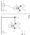
- Fig. 1 shows a body area network (BAN).
- the sensors 101, 103 which are mounted on the body or are for example bonded to it with adhesive, are used to measure an ECG, the SpO2 saturation and blood pressure and to establish a wireless link to a patient information center 107 and to transmit the data on the patient.
- FIG. 1 Shown in Fig. 1 are two scenarios that are typical of the use of body area networks.
- a patient lying in bed is shown on the left-hand side of Fig. 1
- a patient who is up and walking around the hospital is shown on the right-hand side thereof.
- transceiver devices are fitted with measuring sensors and with a transceiver operating to IEEE standard 802.15.4.
- the sensors 101 are directly linked to the patient monitor 105 that is arranged at the bedside.
- the patient monitor 105 in turn is linked directly to the patient information center 107, which is arranged for example in the room serving as the station for the medical staff.
- a transceiver device 103 serves simultaneously as a collecting center for receiving data from the sensors and as a protocol converter, such as a hub for example.
- the sensors first communicate with the protocol converter 103 by means of a short range RF protocol, and the protocol converter 103 then transmits the data, in a mid range RF protocol, via a WLAN for example, to an access point 113, which establishes a wireless link to the patient information center 107.
- the wireless pick-up of measured values allows the patient to move about freely, and consequently the need arises for the communications to be distinguished as communications that are on-body and off-body oriented, so that a suitable transmission protocol can be used at all times.
- a typical protocol for on-body communications is the short range RF protocol under standard IEEE 802.15.4, which standard is often wrongly referred to as ZigBee.
- This standard specifies the physical layer and the MAC layer for low rate wireless personal area networks.
- a transceiver device assumes the role of network coordinator. In the present embodiment it is the first device that is switched on on the network that is the network coordinator.
- the network coordinator is responsible for organizing the data traffic between the individual users of the network. This tasks comprises, on the one hand, dividing the radio channel into time slots, the time slots being short intervals of time in which data is exchanged at the transmitting and receiving ends, in which case access to the channel can be granted by following different rules, such for example as ones giving guaranteed or non-guaranteed rights of access.
- the network coordinator defines the division of the radio channel into the superframe structure in accordance with the present standard IEEE 802.15.4. What this means is that the network coordinator emits a beacon payload as a synchronizing signal and in this way presets the time-based structure of, preferably, 16 time slots.
- a data payload is a number of bits that is treated as a unit when transported.
- the data payload is preferably so designed that its duration is of the same length as that of a time slot.
- the beacon payload is, at the same time, a synchronizing signal and the carrier of the configuring information for the radio channel.
- a superframe comprises 16 intervals of time that are preferably all of the same length and that may be occupied by data payloads.
- the data payloads may be marked as active data payloads or as non-active or inactive data payloads in this case. What is mean by an active data payload or an active interval of time is that the data payload or the interval of time constitutes a period in which all the users on the network are ready to receive or transmit and can be switched to transmit or receive as dictated by the commands shown in the beacon payload.
- the term inactive data payload or inactive time slot means that devices on the network are switched to the energy-saving sleep mode during this time, the transmitter and/or receiver of the transceiver device being switched off.
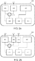
- the device comprises a radio frequency (RF) transceiver 205 in which a first antenna system 201 for on-body communications and a second antenna system 203 for off-body communications can be allocated to the transceiver 205 by means of a switch 213 or some similar, suitable, device. In the present embodiment this process is controlled by the transceiver. In other embodiments however the allocation may also be controlled by some other unit, such as a processor 209 for example.
- the transceiver device 219 also comprises a processor 209, a memory 211 and a sensor 207 for picking up measured values.
- the transceiver device 219 comprising a transceiver 205, a switching device 213, a first antenna system 201 and a second antenna system 203, may take the form of a patient monitor 105 or the form of a hub 103.
- the transceiver device 219 when in the form of a hub or protocol converter 103, may also comprise one or more transceivers or more than two antenna systems 201, 203, 221.
- the basic idea is that of being able to switch between an antenna system 201 for on-body communications and an antenna system 203 for off-body communications, thus, in many cases, enabling an optimized receiving or transmitting polar diagram to be available for the transceiver 205.
- Fig. 3 shows a superframe 311, having individual time slots 309 that are intended for on-body 303 and off-body 305 communications.
- the coordinator notifies the network users how the structure of the superframe is configured and which time slots are intended to be an inactive period 307 or to be periods 303, 305 for on-body and off-body communications.
- all the transceivers 205 on the network that are arranged on-body use the first antenna system 201 for on-body communications, whichever antenna system this may be in the given case, whereas during the times that are intended for off-body communications 305 all the transceivers 205 on the network have recourse to the second antenna system 203 for off-body communications, whichever one this may be in the given case.
- all the devices go into the sleep mode, in which the transceivers 205 are deactivated for example, which means that the current consumption of the transceiver devices 219 is only very low.
- Fig. 4 Shown in Fig. 4 is a new superframe structure 311 according to the present invention.
- this structure provision is made for what are termed contention access periods (CAP) 401, 403 that are designed for on-body communications and off-body communications respectively.
- CAP contention access periods
- the on-body CAP 401 only sensors arranged on-body are allowed, in competition or contention, to obtain for themselves the right to use the channel, and in this way are allowed to communicate with one another.
- the body sensor checks, before it transmits, whether the medium, i.e. the radio channel, is free (listen-before-talk, CSMA/CA).
- a similar process is performed in the case of off-body CAPs 403, it being made possible in this case for the sensors arranged on-body to communicate with off-body devices, and conversely it being made possible for off-body devices to establish links to the sensors arranged on-body.
- the listen-before-talk principle is applied in this latter case too.
- the CAPs are preferably designed for irregular, isolated or intermittent communications because the radio channel is shared with other wireless systems, with all the users accessing the channel on the listen-before-talk principle to prevent them from interfering with one another.
- Fig. 5 is shown an embodiment of the division, by time, of the superframe into guaranteed time slots (GTS) 501, 502, 503, 504, 505, 506, 507.
- GTS guaranteed time slots
- An advantageous result of this is that when the radio channel is being accessed the probability of collisions is only low due to the use of a network coordinator.
- the throughput of data is also increased by the means, which has the known effects as far as the reduction of energy consumption is concerned.
- the body sensor A gets in touch with the body sensor B, in which case the device A uses the entire time slot GTS1 501 for the targeted emission of packets to the device B without observing the listen-before-talk rule.
- GTS guaranteed time slots
- the GTS are intended for communications between users that make regular exchanges of data.
- the assignment of GTS is intended to prevent collisions with other users whose exchange of data traffic is irregular but which operate on the same frequency channel.
- Fig. 6 shows an embodiment of the superframe structure 311.
- the superframe structure begins with the network coordinator's beacon payload 301.
- the beacon payload contains commands relating to the way in which the superframe structure 311 is divided up.
- the active period of the superframe structure 311 comprises CAP (contention access period) time slots 601 for on-body communications and CAP time slots 604 for off-body communications and also GTS (guaranteed time slot) time slots 602, 603 for on-body communications and GTS time slots 605, 606, 607 for off-body communications.
- CAP tention access period
- GTS guard time slot
- time slots can be reserved at the network coordinator.
- a device transmits parameters for specifying the communications requirements by means of a guaranteed time slot specification (GTS spec) 703, for example the number of time slots required, the transmitting address and receiving address 705, to the network coordinator in the form of a time slot request (TS request) 701.
- GTS spec guaranteed time slot specification
- TS request time slot request
- Fig. 8 shows the content of the beacon payload transmission (superframe spec) 801 that, on the basis of the guaranteed time slot request (GTS request) 803, is transmitted to the network coordinator for off-body and on-body communications by means of CAPs and GTS.
- the network coordinator informs the network users of the superframe structure that applies at the time.
- One embodiment comprises the transmission of a beacon payload in which is stored a list 807 that comprises the sequence in which the time slots occur, details of the addressee and the recipient of data payloads, orientation in the form of on-body or off-body orientation, whether the right to transmit is given by CAP or GTS, whether a period is active or inactive and the duration.
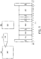
- Fig. 9 shows a detailed, combined example of a division into time slots.
- the beacon payload 801 to give the superframe specification (superframe spec) comprises the items of data 807: time slot duration (in microseconds), number of on-body CAP time slots, number of on-body GTS time slots, specifications of the individual GTS time slots, number of off-body CAP time slots, number of off-body GTS time slots, specifications of the individual off-body GTS time slots and number of inactive time slots.
- GTS spec guaranteed time slots
- the superframe is then put together in the form shown in the bottom part of Fig. 9 .
- the content of the beacon payload notifies all the devices, by reference to the information given in the beacon payload, of when on-body and off-body communications are taking place.
- the transceiver devices in turn allocate the transceivers an antenna system for on-body communications, that is characterized in that the antenna system has an omnidirectional polar diagram that is oriented particularly in the longitudinal direction of the human body, or an antenna system for off-body communications that is characterized in that the antenna system has a polar diagram that points away from the human body.
- the beacon payload is transmitted in parallel by means of the first antenna system for on-body communications and also by means of the second antenna system for off-body communications.
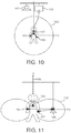
- Fig. 10 describes a preferred polar diagram for antenna systems for on-body communications.
- An antenna system of this kind preferably has an omnidirectional polar diagram 1001.
- the polar diagram is intended to be oriented particularly in the longitudinal direction of the human body.
- An omnidirectional polar diagram of this kind is produced by, for example, a single dipole or a single monopole antenna if the said antenna is so arranged that the direction in which it is of the longest extent is oriented, at the point at which it is located, perpendicularly to the surface of the human body.
- antenna orientations or antenna devices that have a suitable polar diagram to be used as antennas or strip antennas, such for example as slotted antennas or printed circuit board antennas.
- the intention is for the antennas to be so arranged that, together with the transceiver or separately therefrom, they have a polar diagram that is close to the polar diagram 1001 shown in Fig. 10 .
- the radiated power can be reduced to a very low level of transmitted power.
- the transmitted power for on-body communications can be lower than the transmitted power for off-body communications, whereby the reduction in adverse effects, particularly on the human body, is optimized.
- Fig. 11 shows an embodiment of an antenna diagram 1101 for off-body communications.
- What are suitable in the embodiment of a transceiver and antenna system for off-body communications are high operating frequencies that have a low depth of penetration into the human body. Low frequencies that have a comparatively high depth of penetration into the human body and, connected therewith, strong capacitive coupling-in are not suitable for mid range or long range communications links.
- the polar diagram 1101 By the placing of the antenna in a suitably determined position either on the transceiver or in the transceiver device 101, the hub 103 or a protocol converter 103, or the like, the intention is for the polar diagram 1101 to be so oriented that a transceiver arranged off-body from the patent, such as a patient monitor 105 for example, can be reached by a directed polar diagram.
- a patch antenna is able to emit a directed polar diagram oriented off-body when the longitudinal extent of the antenna, relative to its foot point, is arranged parallel to the surface of the human body. Because a higher transmitted power is used for off-body communications in comparison with on-body communications, a strip antenna arrangement or a patch antenna is preferably used. This makes it possible for the human body to be shielded against high levels of transmitted power because strip antenna arrangements have a directed polar diagram.
- Fig. 12 is a schematic view that shows, by way of example, an antenna array having at least two antennas 1201, 1203. It is however also possible for a larger number of antennas to be used.
- the radio-frequency power that is radiated is split into at least two in-phase antenna signals.
- the emission parameters of the two antenna signals may be differently weighted in this case.
- one antenna signal may be delayed in relation to the other by means of a phase shifter 1205.
- the phase shifter 1205 itself is controlled by a processor or by a system for controlling the radio-frequency system by means of a microprocessor. By means of the phase shift, the phase shifter 1205 matches the orientation of the polar diagram of the antenna to the actual requirements that exist, such for example as on-body or off-body communications.
- differently polarized antenna arrangements are used for the first antenna system 1201 and second antenna system 1203.
- a link for on-body communications can for example be made with a horizontally polarized antenna
- a link for off-body communications can be made by a vertically polarized antenna.
- vertically and horizontally oriented antennas may also be replaced by antennas giving dextrorotatory or levorotatory circular polarization.
- a single antenna array may also be used as the first and second antenna systems, the feed of transmitted signals to a first group of the antennas taking place directly and the feed of transmitted signals to the second group of the antennas of the antenna array taking place with a phase shift.
- the transceiver has a phase shifter 1205 for this purpose.
- An embodiment of this kind makes it possible for the polar diagram to be steered in a preferred direction. This is the embodiment that is preferred when the patient is walking around in the hospital while the sensors that he or she has attached to him or her are exchanging data with their surroundings.
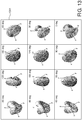
- Fig. 13 shows different polar diagrams 1301 for different phase shifts.
- low-frequency antenna systems such for example as capacitive RF antenna systems that are used for the on-body link.
- Arrangements of this kind use the human body as a capacitive electrical conductor.
- a computer program can be stored or sold on a data-carrying medium, such for example as an optical storage medium or a semiconductor storage medium, that is supplied as a separate component or as an accessory to hardware.
- a computer program may also be distributed in different ways such for example as over the internet or via hard-wired or wireless telecommunications systems.
- the reference numerals in the claims are not to be considered as limiting the invention.
Landscapes
- Engineering & Computer Science (AREA)
- Computer Networks & Wireless Communication (AREA)
- Signal Processing (AREA)
- Mobile Radio Communication Systems (AREA)
- Transceivers (AREA)
Priority Applications (1)
| Application Number | Priority Date | Filing Date | Title |
|---|---|---|---|
| EP10703516.4A EP2392185B1 (en) | 2009-02-02 | 2010-01-28 | Transceiver device for on-body and off-body communications |
Applications Claiming Priority (3)
| Application Number | Priority Date | Filing Date | Title |
|---|---|---|---|
| EP09151872 | 2009-02-02 | ||
| PCT/IB2010/050382 WO2010086813A1 (en) | 2009-02-02 | 2010-01-28 | Transceiver device for on-body and off-body communications |
| EP10703516.4A EP2392185B1 (en) | 2009-02-02 | 2010-01-28 | Transceiver device for on-body and off-body communications |
Publications (2)
| Publication Number | Publication Date |
|---|---|
| EP2392185A1 EP2392185A1 (en) | 2011-12-07 |
| EP2392185B1 true EP2392185B1 (en) | 2018-03-14 |
Family
ID=42109879
Family Applications (1)
| Application Number | Title | Priority Date | Filing Date |
|---|---|---|---|
| EP10703516.4A Active EP2392185B1 (en) | 2009-02-02 | 2010-01-28 | Transceiver device for on-body and off-body communications |
Country Status (7)
| Country | Link |
|---|---|
| US (1) | US8750222B2 (ru) |
| EP (1) | EP2392185B1 (ru) |
| JP (1) | JP5647151B2 (ru) |
| CN (1) | CN102301814B (ru) |
| BR (1) | BRPI1005356A2 (ru) |
| RU (1) | RU2554559C2 (ru) |
| WO (1) | WO2010086813A1 (ru) |
Families Citing this family (24)
| Publication number | Priority date | Publication date | Assignee | Title |
|---|---|---|---|---|
| US9596989B2 (en) | 2009-03-12 | 2017-03-21 | Raytheon Company | Networked symbiotic edge user infrastructure |
| US8798527B2 (en) | 2011-01-14 | 2014-08-05 | Covidien Lp | Wireless relay module for remote monitoring systems |
| US8897198B2 (en) | 2011-01-14 | 2014-11-25 | Covidien Lp | Medical device wireless network architectures |
| US9020419B2 (en) | 2011-01-14 | 2015-04-28 | Covidien, LP | Wireless relay module for remote monitoring systems having power and medical device proximity monitoring functionality |
| US8855550B2 (en) | 2011-01-14 | 2014-10-07 | Covidien Lp | Wireless relay module having emergency call functionality |
| US8903308B2 (en) | 2011-01-14 | 2014-12-02 | Covidien Lp | System and method for patient identification in a remote monitoring system |
| US8811888B2 (en) | 2011-01-14 | 2014-08-19 | Covidien Lp | Wireless relay module for monitoring network status |
| US8818260B2 (en) | 2011-01-14 | 2014-08-26 | Covidien, LP | Wireless relay module for remote monitoring systems |
| US9495511B2 (en) | 2011-03-01 | 2016-11-15 | Covidien Lp | Remote monitoring systems and methods for medical devices |
| US8694600B2 (en) | 2011-03-01 | 2014-04-08 | Covidien Lp | Remote monitoring systems for monitoring medical devices via wireless communication networks |
| US8878735B2 (en) * | 2012-06-25 | 2014-11-04 | Gn Resound A/S | Antenna system for a wearable computing device |
| CA2884437C (en) | 2012-09-13 | 2019-02-26 | Covidien Lp | Docking station and enteral feeding pump system |
| US9031020B2 (en) * | 2012-09-26 | 2015-05-12 | Cisco Technology, Inc. | Using multiple radios to provide service on the same channel to support a new standard while maintaining compatibility with legacy devices |
| CN104937855B (zh) * | 2013-01-25 | 2018-09-11 | Abb研究有限公司 | 用于提供无线传感器网络中的可靠无线通信的方法 |
| JP6115629B2 (ja) * | 2013-03-12 | 2017-04-19 | 富士通株式会社 | 無線通信システム、無線通信方法、送信装置、制御方法、及び、制御プログラム |
| US8953547B2 (en) * | 2013-03-29 | 2015-02-10 | Olympus Corporation | Power-saving TDMA MAC for wireless body area networks |
| USD746441S1 (en) | 2013-09-13 | 2015-12-29 | Covidien Lp | Pump |
| US20170125907A1 (en) * | 2014-07-22 | 2017-05-04 | Kabushiki Kaisha Toshiba | Antenna and method of manufacturing an antenna |
| US20160321846A1 (en) * | 2015-05-01 | 2016-11-03 | Honeywell International Inc. | Security access system using a body area network |
| US9943229B1 (en) * | 2016-12-08 | 2018-04-17 | General Electric Copany | Systems and methods for monitoring patient health |
| US10405374B2 (en) * | 2017-03-17 | 2019-09-03 | Google Llc | Antenna system for head mounted display device |
| JP2019022117A (ja) * | 2017-07-19 | 2019-02-07 | ソニーセミコンダクタソリューションズ株式会社 | 通信装置、および通信システム |
| CN111601387B (zh) * | 2020-05-22 | 2022-07-12 | 电子科技大学 | 一种面向数能一体化无线传感器网络的介质访问控制机制 |
| JP7017284B1 (ja) | 2021-11-16 | 2022-02-08 | 株式会社Foreground | 屋外コンセント |
Family Cites Families (19)
| Publication number | Priority date | Publication date | Assignee | Title |
|---|---|---|---|---|
| US6424820B1 (en) * | 1999-04-02 | 2002-07-23 | Interval Research Corporation | Inductively coupled wireless system and method |
| RU2199943C2 (ru) * | 2001-02-16 | 2003-03-10 | Многопрофильное предприятие ООО "Элсис" | Способ и устройство регистрации пульсовой волны и биометрическая система |
| US7321580B1 (en) * | 2002-10-18 | 2008-01-22 | Bbn Technologies Corp. | Directional carrier sense medium access for wireless nodes |
| US7149581B2 (en) | 2003-01-31 | 2006-12-12 | Medtronic, Inc. | Patient monitoring device with multi-antenna receiver |
| KR100552484B1 (ko) | 2004-02-13 | 2006-02-15 | 삼성전자주식회사 | 무선매체 접근방법 |
| DE102004036878B4 (de) | 2004-07-29 | 2008-04-10 | Dräger Safety AG & Co. KGaA | Verfahren und Vorrichtung zur Funkübertragung von in Körpernähe generierten Signalen |
| RU43749U1 (ru) * | 2004-09-28 | 2005-02-10 | Демин Александр Сергеевич | Устройство физиоконтроля |
| JP5317476B2 (ja) * | 2004-12-13 | 2013-10-16 | コーニンクレッカ フィリップス エヌ ヴェ | モバイルモニタリング |
| EP1881784B1 (en) * | 2005-05-06 | 2013-10-02 | Koninklijke Philips N.V. | Wireless medical monitoring device |
| US9059782B2 (en) * | 2005-06-01 | 2015-06-16 | Broadcom Corporation | Method and system for antenna and radio front-end topologies for a system-on-a-chip (SOC) device that combines bluetooth and IEEE 802.11 b/g WLAN technologies |
| US7778219B2 (en) | 2005-11-17 | 2010-08-17 | San Diego Research Center, Inc. | Directional transmission and reception in a mobile wireless ad hoc network |
| JP4163717B2 (ja) * | 2006-01-24 | 2008-10-08 | 日本電信電話株式会社 | 呼出し応答システムとその呼出し装置及び応答装置 |
| US7742816B2 (en) * | 2006-03-31 | 2010-06-22 | Medtronic, Inc. | Multichannel communication for implantable medical device applications |
| DE102007003634B3 (de) | 2006-09-14 | 2008-04-24 | IHP GmbH - Innovations for High Performance Microelectronics/Institut für innovative Mikroelektronik | Hardware-Protokollbeschleuniger für eine Verbindungssicherungs-Protokollebene eines Senderempfängers |
| JP4840043B2 (ja) * | 2006-09-21 | 2011-12-21 | ソニー株式会社 | 無線通信システムおよび無線通信装置 |
| US20080113621A1 (en) | 2006-11-07 | 2008-05-15 | Jayant Parthasarathy | Wireless Medical Device Communication System |
| US20080294020A1 (en) * | 2007-01-25 | 2008-11-27 | Demetrios Sapounas | System and method for physlological data readings, transmission and presentation |
| WO2008097524A2 (en) | 2007-02-05 | 2008-08-14 | Senior Vitals, Inc. | System and method for physiological data readings, transmission and presentation |
| EP2214447B1 (en) * | 2009-01-29 | 2016-03-30 | Stichting IMEC Nederland | Access method and data frame structure for use in body area networks |
-
2010
- 2010-01-28 JP JP2011547042A patent/JP5647151B2/ja active Active
- 2010-01-28 WO PCT/IB2010/050382 patent/WO2010086813A1/en active Application Filing
- 2010-01-28 CN CN201080006352.8A patent/CN102301814B/zh active Active
- 2010-01-28 RU RU2011136480/08A patent/RU2554559C2/ru not_active IP Right Cessation
- 2010-01-28 EP EP10703516.4A patent/EP2392185B1/en active Active
- 2010-01-28 US US13/146,019 patent/US8750222B2/en active Active
- 2010-01-28 BR BRPI1005356A patent/BRPI1005356A2/pt not_active Application Discontinuation
Also Published As
| Publication number | Publication date |
|---|---|
| CN102301814B (zh) | 2016-05-11 |
| BRPI1005356A2 (pt) | 2017-12-12 |
| JP5647151B2 (ja) | 2014-12-24 |
| EP2392185A1 (en) | 2011-12-07 |
| JP2012517135A (ja) | 2012-07-26 |
| RU2554559C2 (ru) | 2015-06-27 |
| US8750222B2 (en) | 2014-06-10 |
| CN102301814A (zh) | 2011-12-28 |
| US20110280224A1 (en) | 2011-11-17 |
| WO2010086813A1 (en) | 2010-08-05 |
| RU2011136480A (ru) | 2013-03-10 |
Similar Documents
| Publication | Publication Date | Title |
|---|---|---|
| EP2392185B1 (en) | Transceiver device for on-body and off-body communications | |
| KR101244555B1 (ko) | 신체 영역 네트워크에 대한 개선 | |
| Ullah et al. | A comprehensive survey of wireless body area networks: On PHY, MAC, and network layers solutions | |
| EP2356733B1 (en) | Method and system of radio frequency (rf) power transmission in a wireless network | |
| Rahim et al. | A comprehensive survey of MAC protocols for wireless body area networks | |
| EP2314122B1 (en) | A medium access control (mac) protocol for body area networks | |
| JP5362101B2 (ja) | ボディエリアネットワークにおけるピコネットを駆動するための装置及び方法 | |
| JP2012517135A5 (ru) | ||
| Sruthi | Medium access control protocols for wireless body area networks: A survey | |
| US20100272076A1 (en) | Simplified beaconing and channel reservation techniques for short range wireless networks | |
| JP2012519440A (ja) | 近距離無線ネットワークの改善 | |
| EP2725864B1 (en) | Radio communication device, method for controlling radio communication, and radio communication system | |
| Ashraf et al. | Energy-efficient dynamic channel allocation algorithm in wireless body area network | |
| KR101639113B1 (ko) | 의료 신체 영역 네트워크에서의 채널 전환 방법 | |
| Ghias et al. | Towards energy-and interference-aware health monitoring by using WBANs in medicine services | |
| EP2424304A1 (en) | Method and network manager device for scheduling a transmission of messages within a wireless network | |
| KR20140031926A (ko) | 의료 신체 영역 네트워크에서의 채널 탐색 방법 | |
| Wang et al. | IEEE 802.15. 4J: extend IEEE 802.15. 4 radio into the MBAN spectrum [Industry Perspectives] | |
| Kaur et al. | Wireless body area network: Performance analysis of polling access MAC protocol | |
| KR20100113963A (ko) | Ban에서의 주기 설정 방법 | |
| Gama et al. | A time-slot scheduling algorithm for e-health wireless sensor networks | |
| KR20140004198A (ko) | 의료 신체 영역 네트워크에서의 채널 초기화 방법 | |
| US9681440B2 (en) | Method and device for scheduling a wireless personal area network | |
| Torabi et al. | Robust access for wireless body area networks in public m-health | |
| Hur et al. | A WBAN beacon structure for wireless USB protocol adaptation |
Legal Events
| Date | Code | Title | Description |
|---|---|---|---|
| PUAI | Public reference made under article 153(3) epc to a published international application that has entered the european phase |
Free format text: ORIGINAL CODE: 0009012 |
|
| 17P | Request for examination filed |
Effective date: 20110902 |
|
| AK | Designated contracting states |
Kind code of ref document: A1 Designated state(s): AT BE BG CH CY CZ DE DK EE ES FI FR GB GR HR HU IE IS IT LI LT LU LV MC MK MT NL NO PL PT RO SE SI SK SM TR |
|
| DAX | Request for extension of the european patent (deleted) | ||
| RAP1 | Party data changed (applicant data changed or rights of an application transferred) |
Owner name: KONINKLIJKE PHILIPS N.V. Owner name: PHILIPS INTELLECTUAL PROPERTY & STANDARDS GMBH |
|
| 17Q | First examination report despatched |
Effective date: 20131014 |
|
| GRAP | Despatch of communication of intention to grant a patent |
Free format text: ORIGINAL CODE: EPIDOSNIGR1 |
|
| STAA | Information on the status of an ep patent application or granted ep patent |
Free format text: STATUS: GRANT OF PATENT IS INTENDED |
|
| GRAJ | Information related to disapproval of communication of intention to grant by the applicant or resumption of examination proceedings by the epo deleted |
Free format text: ORIGINAL CODE: EPIDOSDIGR1 |
|
| RIC1 | Information provided on ipc code assigned before grant |
Ipc: H04W 72/12 20090101AFI20170427BHEP Ipc: H04W 88/06 20090101ALN20170427BHEP |
|
| STAA | Information on the status of an ep patent application or granted ep patent |
Free format text: STATUS: EXAMINATION IS IN PROGRESS |
|
| INTG | Intention to grant announced |
Effective date: 20170517 |
|
| GRAP | Despatch of communication of intention to grant a patent |
Free format text: ORIGINAL CODE: EPIDOSNIGR1 |
|
| INTC | Intention to grant announced (deleted) | ||
| RIC1 | Information provided on ipc code assigned before grant |
Ipc: H04W 72/12 20090101AFI20170601BHEP Ipc: H04W 88/06 20090101ALN20170601BHEP |
|
| STAA | Information on the status of an ep patent application or granted ep patent |
Free format text: STATUS: GRANT OF PATENT IS INTENDED |
|
| INTG | Intention to grant announced |
Effective date: 20170706 |
|
| GRAJ | Information related to disapproval of communication of intention to grant by the applicant or resumption of examination proceedings by the epo deleted |
Free format text: ORIGINAL CODE: EPIDOSDIGR1 |
|
| STAA | Information on the status of an ep patent application or granted ep patent |
Free format text: STATUS: EXAMINATION IS IN PROGRESS |
|
| REG | Reference to a national code |
Ref country code: DE Ref legal event code: R079 Ref document number: 602010049152 Country of ref document: DE Free format text: PREVIOUS MAIN CLASS: H04W0074040000 Ipc: H04W0072120000 |
|
| INTC | Intention to grant announced (deleted) | ||
| GRAP | Despatch of communication of intention to grant a patent |
Free format text: ORIGINAL CODE: EPIDOSNIGR1 |
|
| STAA | Information on the status of an ep patent application or granted ep patent |
Free format text: STATUS: GRANT OF PATENT IS INTENDED |
|
| RIC1 | Information provided on ipc code assigned before grant |
Ipc: H04W 88/06 20090101ALN20170829BHEP Ipc: H04W 72/12 20090101AFI20170829BHEP |
|
| INTG | Intention to grant announced |
Effective date: 20171004 |
|
| GRAS | Grant fee paid |
Free format text: ORIGINAL CODE: EPIDOSNIGR3 |
|
| GRAA | (expected) grant |
Free format text: ORIGINAL CODE: 0009210 |
|
| STAA | Information on the status of an ep patent application or granted ep patent |
Free format text: STATUS: THE PATENT HAS BEEN GRANTED |
|
| AK | Designated contracting states |
Kind code of ref document: B1 Designated state(s): AT BE BG CH CY CZ DE DK EE ES FI FR GB GR HR HU IE IS IT LI LT LU LV MC MK MT NL NO PL PT RO SE SI SK SM TR |
|
| REG | Reference to a national code |
Ref country code: GB Ref legal event code: FG4D |
|
| REG | Reference to a national code |
Ref country code: CH Ref legal event code: EP Ref country code: AT Ref legal event code: REF Ref document number: 980021 Country of ref document: AT Kind code of ref document: T Effective date: 20180315 |
|
| REG | Reference to a national code |
Ref country code: IE Ref legal event code: FG4D |
|
| REG | Reference to a national code |
Ref country code: DE Ref legal event code: R096 Ref document number: 602010049152 Country of ref document: DE |
|
| REG | Reference to a national code |
Ref country code: NL Ref legal event code: MP Effective date: 20180314 |
|
| REG | Reference to a national code |
Ref country code: LT Ref legal event code: MG4D |
|
| PG25 | Lapsed in a contracting state [announced via postgrant information from national office to epo] |
Ref country code: ES Free format text: LAPSE BECAUSE OF FAILURE TO SUBMIT A TRANSLATION OF THE DESCRIPTION OR TO PAY THE FEE WITHIN THE PRESCRIBED TIME-LIMIT Effective date: 20180314 Ref country code: HR Free format text: LAPSE BECAUSE OF FAILURE TO SUBMIT A TRANSLATION OF THE DESCRIPTION OR TO PAY THE FEE WITHIN THE PRESCRIBED TIME-LIMIT Effective date: 20180314 Ref country code: NO Free format text: LAPSE BECAUSE OF FAILURE TO SUBMIT A TRANSLATION OF THE DESCRIPTION OR TO PAY THE FEE WITHIN THE PRESCRIBED TIME-LIMIT Effective date: 20180614 Ref country code: FI Free format text: LAPSE BECAUSE OF FAILURE TO SUBMIT A TRANSLATION OF THE DESCRIPTION OR TO PAY THE FEE WITHIN THE PRESCRIBED TIME-LIMIT Effective date: 20180314 Ref country code: LT Free format text: LAPSE BECAUSE OF FAILURE TO SUBMIT A TRANSLATION OF THE DESCRIPTION OR TO PAY THE FEE WITHIN THE PRESCRIBED TIME-LIMIT Effective date: 20180314 Ref country code: CY Free format text: LAPSE BECAUSE OF FAILURE TO SUBMIT A TRANSLATION OF THE DESCRIPTION OR TO PAY THE FEE WITHIN THE PRESCRIBED TIME-LIMIT Effective date: 20180314 |
|
| REG | Reference to a national code |
Ref country code: AT Ref legal event code: MK05 Ref document number: 980021 Country of ref document: AT Kind code of ref document: T Effective date: 20180314 |
|
| PG25 | Lapsed in a contracting state [announced via postgrant information from national office to epo] |
Ref country code: LV Free format text: LAPSE BECAUSE OF FAILURE TO SUBMIT A TRANSLATION OF THE DESCRIPTION OR TO PAY THE FEE WITHIN THE PRESCRIBED TIME-LIMIT Effective date: 20180314 Ref country code: SE Free format text: LAPSE BECAUSE OF FAILURE TO SUBMIT A TRANSLATION OF THE DESCRIPTION OR TO PAY THE FEE WITHIN THE PRESCRIBED TIME-LIMIT Effective date: 20180314 Ref country code: GR Free format text: LAPSE BECAUSE OF FAILURE TO SUBMIT A TRANSLATION OF THE DESCRIPTION OR TO PAY THE FEE WITHIN THE PRESCRIBED TIME-LIMIT Effective date: 20180615 Ref country code: BG Free format text: LAPSE BECAUSE OF FAILURE TO SUBMIT A TRANSLATION OF THE DESCRIPTION OR TO PAY THE FEE WITHIN THE PRESCRIBED TIME-LIMIT Effective date: 20180614 |
|
| PG25 | Lapsed in a contracting state [announced via postgrant information from national office to epo] |
Ref country code: RO Free format text: LAPSE BECAUSE OF FAILURE TO SUBMIT A TRANSLATION OF THE DESCRIPTION OR TO PAY THE FEE WITHIN THE PRESCRIBED TIME-LIMIT Effective date: 20180314 Ref country code: EE Free format text: LAPSE BECAUSE OF FAILURE TO SUBMIT A TRANSLATION OF THE DESCRIPTION OR TO PAY THE FEE WITHIN THE PRESCRIBED TIME-LIMIT Effective date: 20180314 Ref country code: PL Free format text: LAPSE BECAUSE OF FAILURE TO SUBMIT A TRANSLATION OF THE DESCRIPTION OR TO PAY THE FEE WITHIN THE PRESCRIBED TIME-LIMIT Effective date: 20180314 Ref country code: NL Free format text: LAPSE BECAUSE OF FAILURE TO SUBMIT A TRANSLATION OF THE DESCRIPTION OR TO PAY THE FEE WITHIN THE PRESCRIBED TIME-LIMIT Effective date: 20180314 |
|
| PG25 | Lapsed in a contracting state [announced via postgrant information from national office to epo] |
Ref country code: SM Free format text: LAPSE BECAUSE OF FAILURE TO SUBMIT A TRANSLATION OF THE DESCRIPTION OR TO PAY THE FEE WITHIN THE PRESCRIBED TIME-LIMIT Effective date: 20180314 Ref country code: AT Free format text: LAPSE BECAUSE OF FAILURE TO SUBMIT A TRANSLATION OF THE DESCRIPTION OR TO PAY THE FEE WITHIN THE PRESCRIBED TIME-LIMIT Effective date: 20180314 Ref country code: CZ Free format text: LAPSE BECAUSE OF FAILURE TO SUBMIT A TRANSLATION OF THE DESCRIPTION OR TO PAY THE FEE WITHIN THE PRESCRIBED TIME-LIMIT Effective date: 20180314 Ref country code: SK Free format text: LAPSE BECAUSE OF FAILURE TO SUBMIT A TRANSLATION OF THE DESCRIPTION OR TO PAY THE FEE WITHIN THE PRESCRIBED TIME-LIMIT Effective date: 20180314 |
|
| REG | Reference to a national code |
Ref country code: DE Ref legal event code: R097 Ref document number: 602010049152 Country of ref document: DE |
|
| PG25 | Lapsed in a contracting state [announced via postgrant information from national office to epo] |
Ref country code: PT Free format text: LAPSE BECAUSE OF FAILURE TO SUBMIT A TRANSLATION OF THE DESCRIPTION OR TO PAY THE FEE WITHIN THE PRESCRIBED TIME-LIMIT Effective date: 20180716 |
|
| PLBE | No opposition filed within time limit |
Free format text: ORIGINAL CODE: 0009261 |
|
| STAA | Information on the status of an ep patent application or granted ep patent |
Free format text: STATUS: NO OPPOSITION FILED WITHIN TIME LIMIT |
|
| PG25 | Lapsed in a contracting state [announced via postgrant information from national office to epo] |
Ref country code: DK Free format text: LAPSE BECAUSE OF FAILURE TO SUBMIT A TRANSLATION OF THE DESCRIPTION OR TO PAY THE FEE WITHIN THE PRESCRIBED TIME-LIMIT Effective date: 20180314 |
|
| 26N | No opposition filed |
Effective date: 20181217 |
|
| PG25 | Lapsed in a contracting state [announced via postgrant information from national office to epo] |
Ref country code: IT Free format text: LAPSE BECAUSE OF FAILURE TO SUBMIT A TRANSLATION OF THE DESCRIPTION OR TO PAY THE FEE WITHIN THE PRESCRIBED TIME-LIMIT Effective date: 20180314 Ref country code: SI Free format text: LAPSE BECAUSE OF FAILURE TO SUBMIT A TRANSLATION OF THE DESCRIPTION OR TO PAY THE FEE WITHIN THE PRESCRIBED TIME-LIMIT Effective date: 20180314 |
|
| PG25 | Lapsed in a contracting state [announced via postgrant information from national office to epo] |
Ref country code: MC Free format text: LAPSE BECAUSE OF FAILURE TO SUBMIT A TRANSLATION OF THE DESCRIPTION OR TO PAY THE FEE WITHIN THE PRESCRIBED TIME-LIMIT Effective date: 20180314 |
|
| REG | Reference to a national code |
Ref country code: CH Ref legal event code: PL |
|
| GBPC | Gb: european patent ceased through non-payment of renewal fee |
Effective date: 20190128 |
|
| PG25 | Lapsed in a contracting state [announced via postgrant information from national office to epo] |
Ref country code: LU Free format text: LAPSE BECAUSE OF NON-PAYMENT OF DUE FEES Effective date: 20190128 |
|
| REG | Reference to a national code |
Ref country code: BE Ref legal event code: MM Effective date: 20190131 |
|
| REG | Reference to a national code |
Ref country code: IE Ref legal event code: MM4A |
|
| PG25 | Lapsed in a contracting state [announced via postgrant information from national office to epo] |
Ref country code: BE Free format text: LAPSE BECAUSE OF NON-PAYMENT OF DUE FEES Effective date: 20190131 |
|
| PG25 | Lapsed in a contracting state [announced via postgrant information from national office to epo] |
Ref country code: CH Free format text: LAPSE BECAUSE OF NON-PAYMENT OF DUE FEES Effective date: 20190131 Ref country code: LI Free format text: LAPSE BECAUSE OF NON-PAYMENT OF DUE FEES Effective date: 20190131 Ref country code: GB Free format text: LAPSE BECAUSE OF NON-PAYMENT OF DUE FEES Effective date: 20190128 |
|
| PG25 | Lapsed in a contracting state [announced via postgrant information from national office to epo] |
Ref country code: IE Free format text: LAPSE BECAUSE OF NON-PAYMENT OF DUE FEES Effective date: 20190128 |
|
| PG25 | Lapsed in a contracting state [announced via postgrant information from national office to epo] |
Ref country code: TR Free format text: LAPSE BECAUSE OF FAILURE TO SUBMIT A TRANSLATION OF THE DESCRIPTION OR TO PAY THE FEE WITHIN THE PRESCRIBED TIME-LIMIT Effective date: 20180314 |
|
| PG25 | Lapsed in a contracting state [announced via postgrant information from national office to epo] |
Ref country code: MT Free format text: LAPSE BECAUSE OF NON-PAYMENT OF DUE FEES Effective date: 20190128 |
|
| REG | Reference to a national code |
Ref country code: DE Ref legal event code: R081 Ref document number: 602010049152 Country of ref document: DE Owner name: PHILIPS GMBH, DE Free format text: FORMER OWNER: PHILIPS INTELLECTUAL PROPERTY & STANDARDS GMBH, 20099 HAMBURG, DE |
|
| PG25 | Lapsed in a contracting state [announced via postgrant information from national office to epo] |
Ref country code: IS Free format text: LAPSE BECAUSE OF FAILURE TO SUBMIT A TRANSLATION OF THE DESCRIPTION OR TO PAY THE FEE WITHIN THE PRESCRIBED TIME-LIMIT Effective date: 20180714 |
|
| PG25 | Lapsed in a contracting state [announced via postgrant information from national office to epo] |
Ref country code: HU Free format text: LAPSE BECAUSE OF FAILURE TO SUBMIT A TRANSLATION OF THE DESCRIPTION OR TO PAY THE FEE WITHIN THE PRESCRIBED TIME-LIMIT; INVALID AB INITIO Effective date: 20100128 |
|
| PG25 | Lapsed in a contracting state [announced via postgrant information from national office to epo] |
Ref country code: MK Free format text: LAPSE BECAUSE OF FAILURE TO SUBMIT A TRANSLATION OF THE DESCRIPTION OR TO PAY THE FEE WITHIN THE PRESCRIBED TIME-LIMIT Effective date: 20180314 |
|
| PGFP | Annual fee paid to national office [announced via postgrant information from national office to epo] |
Ref country code: FR Payment date: 20230124 Year of fee payment: 14 |
|
| PGFP | Annual fee paid to national office [announced via postgrant information from national office to epo] |
Ref country code: DE Payment date: 20240129 Year of fee payment: 15 |