EP2390987B1 - Electric machine rotor bar and method of making same - Google Patents
Electric machine rotor bar and method of making same Download PDFInfo
- Publication number
- EP2390987B1 EP2390987B1 EP11167545.0A EP11167545A EP2390987B1 EP 2390987 B1 EP2390987 B1 EP 2390987B1 EP 11167545 A EP11167545 A EP 11167545A EP 2390987 B1 EP2390987 B1 EP 2390987B1
- Authority
- EP
- European Patent Office
- Prior art keywords
- metallic material
- ring
- rotor
- electric machine
- bars
- Prior art date
- Legal status (The legal status is an assumption and is not a legal conclusion. Google has not performed a legal analysis and makes no representation as to the accuracy of the status listed.)
- Active
Links
Images


Classifications
-
- H—ELECTRICITY
- H02—GENERATION; CONVERSION OR DISTRIBUTION OF ELECTRIC POWER
- H02K—DYNAMO-ELECTRIC MACHINES
- H02K3/00—Details of windings
- H02K3/04—Windings characterised by the conductor shape, form or construction, e.g. with bar conductors
- H02K3/12—Windings characterised by the conductor shape, form or construction, e.g. with bar conductors arranged in slots
-
- B—PERFORMING OPERATIONS; TRANSPORTING
- B22—CASTING; POWDER METALLURGY
- B22D—CASTING OF METALS; CASTING OF OTHER SUBSTANCES BY THE SAME PROCESSES OR DEVICES
- B22D19/00—Casting in, on, or around objects which form part of the product
- B22D19/0054—Casting in, on, or around objects which form part of the product rotors, stators for electrical motors
-
- H—ELECTRICITY
- H02—GENERATION; CONVERSION OR DISTRIBUTION OF ELECTRIC POWER
- H02K—DYNAMO-ELECTRIC MACHINES
- H02K15/00—Processes or apparatus specially adapted for manufacturing, assembling, maintaining or repairing of dynamo-electric machines
- H02K15/02—Processes or apparatus specially adapted for manufacturing, assembling, maintaining or repairing of dynamo-electric machines of stator or rotor bodies
- H02K15/021—Magnetic cores
- H02K15/023—Cage rotors
-
- Y—GENERAL TAGGING OF NEW TECHNOLOGICAL DEVELOPMENTS; GENERAL TAGGING OF CROSS-SECTIONAL TECHNOLOGIES SPANNING OVER SEVERAL SECTIONS OF THE IPC; TECHNICAL SUBJECTS COVERED BY FORMER USPC CROSS-REFERENCE ART COLLECTIONS [XRACs] AND DIGESTS
- Y10—TECHNICAL SUBJECTS COVERED BY FORMER USPC
- Y10T—TECHNICAL SUBJECTS COVERED BY FORMER US CLASSIFICATION
- Y10T29/00—Metal working
- Y10T29/49—Method of mechanical manufacture
- Y10T29/49002—Electrical device making
- Y10T29/49009—Dynamoelectric machine
- Y10T29/49012—Rotor
Definitions
- the disclosure relates generally to electric machine rotor bars and, more particularly, to a bi-metallic electric machine rotor bar.
- rotor bars of an electric machine such as an electric motor or generator are manufactured of one material.
- rotor bars are often made of aluminum because of its electrical properties and the costs associated with "working" aluminum.
- rotor bars have been manufactured from materials having a lower electrical resistance than aluminum.
- rotors bars made up of copper have been manufactured.
- copper rotor bars tend to be more costly than aluminum rotor bars.
- JPH 1028360 A describes an induction motor with copper rods coated with aluminum films and bonding the aluminum to the copper.
- JPH 09266647 A describes a rotor structure of a motor with an end ring, a mounting bolt, the current passages, a slot bar, and a disc-shaped member plated with gold.
- US 6088906 A describes methods to manufacture motor rotors with joining an end ring with conductors extending from core slots having a different material than the end ring.
- an electric machine according to claim 1.
- electric machine 100 has an axis of rotation 102 about which it rotates. Though not shown, but as would be appreciated by those skilled in the art, a shaft along axis of rotation 102 would, once rotated, cause electric machine 100 to rotate. It is contemplated that electric machine 100 may include a plurality of cooling fins 104 (shown in phantom). Examples without cooling fins 104 or with a greater or lower number of cooling fins than those shown in FIG. 1 are, however, envisioned.
- electric machine 100 may be of any type of electric machine that employs rotor bars.
- such electric machines may include an induction machine such as an induction motor or generator.
- such an electric machine may also include electric motors, generators, or the like.
- electric machine 100 includes a plurality of rotor bars.
- Electric machine 100 includes a plurality of rotor bars 106 extending through a core material 108 (i.e., a rotor bar housing) of electric machine 100, where each rotor bar of the plurality of rotor bars 106 includes at least a first metallic material 110 and a second metallic material 112.
- First metallic material 110 has a first electrical resistivity
- second metallic material 112 has a second electrical resistivity greater than the first electrical resistivity.
- each rotor bar 106 includes an upper portion 114 and a lower portion 116.
- first metallic material 110 includes a copper material (e.g., a copper bar) and/or a silver material while second metallic material 112 includes an aluminum material. It is envisioned, however, that first metallic material 110 may be constructed of a material other than copper or silver.
- first metallic material 110 may be constructed of a first type of aluminum having a corresponding first electrical resistivity
- second metallic material 112 may be constructed of a second type of aluminum having a corresponding second electrical resistivity different from the first electrical resistivity.
- the first type of aluminum of first metallic material 110 would have an electrical resistivity less than that of the second type of aluminum of second metallic material 112.
- second metallic material 112 may be constructed of a material other than aluminum.
- second metallic material 112 is a material cast about first metallic material 110.
- the running efficiency of electric machine 100 is generally more influenced by lower portion 116 of each rotor bar 106. As electrical resistivity of lower portion 116 decreases, the running efficiency of electric machine 100 increases.
- starting torque of electric machine portion 100 may be influenced by upper portion 114 of each rotor bar 106.
- the electrical resistivity of upper portion 114 increases, so may the starting torque.
- the electrical excitation is from a fixed frequency source such as line-starting from an AC 60 Hz source.
- Examples of the disclosure aid in maximizing or at least increasing the running efficiency of an electric machine (e.g., electric machine 100). Examples of the disclosure may also aid in increasing starting torque of an electric machine and/or limiting starting current of an electric machine. For example, the higher electrical resistivity of upper portion 114, due to the higher electrical resistivity of second metallic material 112, may increase starting torque and/or limit starting current. Further, since lower portion 116 includes first metallic material 110 having a lower electrical resistivity than second metallic material 112, the running efficiency of a corresponding electric machine (e.g., electric machine 100) increases.
- second metallic material 112 may be chosen to maximize or increase starting torque and/or limit starting current, while first metallic material 110 can be chosen to maximize or increase running efficiency.
- the higher electrical resistivity of upper portion 114, due to second metallic material 112 may have a positive effect on the starting torque or starting current of electric machine 100
- lower portion 116 due to the lower electrical resistivity of first metallic material 110 of lower portion 116, has a positive effect on the running efficiency of electric machine 100.
- second material 112 may be cast about first material 110. It is envisioned, however, that upper portion 114 of rotor bar 106 may be a preformed component. In such an example, the preformed component may be constructed of the same material as second material 112, or it may be constructed of another material. In either case, the preformed component has an electrical resistivity higher than the electrical resistivity of first material 110.
- examples of the disclosure may be employed to take advantage of the benefits of using high electrical resistivity rotor bars while reducing or limiting the manufacturing costs associated therewith.
- it is typically more expensive to manufacture an electric machine employing rotor bars made entirely of copper than to manufacture an electric machine that employs rotor bars made entirely of aluminum (i.e., a rotor bar typically having a higher electrical resistivity than a copper rotor bar).
- Such manufacturing cost differentials can be associated with the higher melting point of copper, which can necessitate more expensive tool and manufacturing processes. For example, it is often more expensive to cast copper than it is to cast aluminum.
- first metallic material 110 may be a pre-purchased copper bar either having the appropriate dimensions or may be machined to have the appropriate dimension, whereas second metallic material 112 may be cast about first metallic material 110. Accordingly, the need to cast first metallic material 110 may be avoided.
- FIGS. 3-5 illustrate a portion of electric machine 100 along line 5-5 of FIG. 2 and show an example of manufacturing a rotor bar according to an example of the disclosure.
- first metallic material 110 may be a bar or bar-like material.
- first metallic material 110 may have an intervening material 120 thereon.
- Intervening material 120 may be a cladding (e.g., an aluminum, nickel, or other type of cladding).
- intervening material 120 may be an insulating material. It is noted, however, that examples free of an intervening material are also contemplated. Further details regarding intervening material 120 will be set forth below with respect to FIG. 5 .
- FIG. 5 illustrates that cast material 112 (i.e., second metallic material) fills the remaining void of opening 118 and is cast about first metallic material 110 and about intervening material 120 if present.
- intervening material 120 may be an electrical insulator configured to at least partially electrically isolate cast material 112 from first material 110.
- intervening material 120 may be a cladding (e.g., an aluminum cladding) configured to enhance adhesion or coupling between first material 110 and cast material 112.
- cladding e.g., an aluminum cladding
- cast material 112 of rotor bar 106 need not entirely cover first material 110.
- a bottom portion 122 of first material 110/intervening material 120 combination is adjacent to rotor core 108 without cast material 112 therebetween. Accordingly, casting material 112 can either fully or partially surround first material insert 110 depending on the location of first material 110 within opening 118.
- rotor bar 106 includes upper portion 114 and lower portion 116.
- First metallic material 110 has a lower electrical resistance than cast material 112. Accordingly, the effective electrical resistance of lower portion 116 is lower than the effective electrical resistance of upper portion 114. Due to the lower effective electrical resistance of lower portion 116, electric machine 100 will have a higher running efficiency than a comparable electric machine (not shown) that employs rotor bars containing only cast material 112.
- electric machine 100 may have a higher starting torque than a comparable machine (not shown) that employs rotor bars containing only the material employed for first metallic material 110 (e.g., copper). Further, the configuration of rotor bar 106 may also be beneficial in limiting starting current.
- electric machine 100 may benefit from the higher electrical resistance properties of cast material 112 while also benefiting from the lower electrical resistance properties of first metallic material 110
- electric machine 100 includes a first coupling component 124 (i.e., a first ring), rotor core 108 having openings 118 therein, and a second coupling component 126 (i.e., a second ring).
- first coupling component 124 i.e., a first ring
- second coupling component 126 i.e., a second ring
- the plurality of rotor bars 106 are also shown in an exploded view, where each rotor bar 106 includes a first metallic material 110 and a second metallic material 112.
- second metallic material 112 is shown as two components (i.e., one component next to first ring 124 and another component next to second ring 126) for illustrative purposes. According to examples where second metallic material 112 is cast about first metallic material 110, second metallic material 112 is one component.
- first metallic material 110 may have an intervening material (e.g., intervening material 120 of FIGS. 4-5 ) coupled thereto. If the intervening material is an insulator, first and second coupling components 124, 126 would also be substantially encased in the insulating material such that first metallic material 110 and first and second coupling components 124, 126 are electrically coupled together but substantially electrically isolated from second metallic material 112.
- intervening material e.g., intervening material 120 of FIGS. 4-5
- first and second coupling components 124, 126 would also be substantially encased in the insulating material such that first metallic material 110 and first and second coupling components 124, 126 are electrically coupled together but substantially electrically isolated from second metallic material 112.
- first metallic material 110 has a lower electrical resistance than second metallic material 112.
- First metallic material 110 may be a bar or bar-like material, which is placed in an opening 118.
- first and second coupling components 124, 126 are coupled thereto. Though first and second coupling components 124, 126 are shown as being circular or ring-shaped in the example depicted in FIG. 6 , other shapes are contemplated.
- second metallic material 112 may be cast around first metallic material 110 into opening 118. As such, the manufacturing costs associated with casting first metallic material 110 may be avoided since first metallic material 110 need not be cast. According to the examples depicted in FIGS. 1 and 6 , second metallic material 112 is also cast about first and second coupling components 124, 126.
- FIG. 7 a cross-sectional view of electric machine 100 along line 7-7 of FIG. 1 is shown according to an example of the disclosure.
- a first rotor bar 128 and a second rotor bar 130 are shown in FIG. 7 , where each rotor bar 128, 130 includes first metallic material 110 and a second metallic material 112.
- first ring 124 i.e., a first coupling component
- second ring 126 i.e., a second coupling component
- each ring 124, 126 electrically couples first and second rotor bars 128, 130 to the other rotors bars (not shown) positioned about the circumference of electric machine 100.
- first and second rings 124, 126 may be brazed to first material 110 to enable or enhance the electric coupling therebetween.
- electric machine 100 shown in FIG. 7 does not include cooling fins (e.g., cooling fins 104 of FIG. 1 ).
- cooling fins e.g., cooling fins 104 of FIG. 1
- examples of an electric machine, such as electric machine 100, having cooling fins are contemplated.
- FIGS. 8-10 show steps for securing first metallic material 110 to first ring 124 and second ring 126 prior to the casting of second metallic material 112 thereabout according to an example of the disclosure.
- a compression tool 132 is aligned with a first end 134 and a second end 136 of first metallic material 110.
- compression tool 132 applies pressure to first and second ends 134, 136, thus deforming first and second ends 134, 136 such that they overlap a portion of a first ring 124 and a portion of a second ring 126, respectively.
- compression tool 132 is removed from deformed first and second ends 134, 136, thus leaving a low resistance contact 138 formed between first metallic material 110 and first and second rings 124, 126.
- the low resistance contacts 138 thus formed ensure that first and second rings 124, 126 electrically couple all rotor bars 106 together as described above.
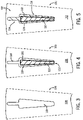
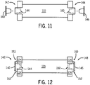
- FIGS. 11-12 show steps for securing first metallic material 110 to first ring 124 and second ring 126 prior to the casting of second metallic material 112 thereabout according to another example of the disclosure.
- a first screw cap 140 is aligned with a first end 142 of a first metallic material 110, which has a first cavity 144 formed therein, and a second screw cap 146 is aligned with a second end 148 of first metallic material 110, which has a second cavity 150 formed therein.
- first and second screw caps 140, 146 are screwed into first and second cavities 144, 150 of first metallic material 110, thus causing first metallic material 110 to overlap first ring 124 and second ring 126.
- a low resistance contact 152 is formed between first metallic material 110 and first and second rings 124, 126. In this manner, the low resistance contacts 152 thus formed ensure that first and second rings 124, 126 electrically couple all rotor bars 106 together as described above.
- second metallic material 112 is cast around first metallic material 110 and first and second rings 124, 126 with first and second screw caps 140, 146 left inserted into first metallic material 110. In this manner, second metallic material 112 is cast around first and second screw caps 140, 146. According to another example, first and second screw caps 140, 146 may be removed prior to casting.
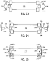
- FIGS. 13-15 show steps for securing first metallic material 110 to first ring 124 and second ring 126 prior to the casting of second metallic material 112 thereabout according to another example of the disclosure.
- first washer 154 is aligned with a first end 156 of first metallic material 110
- second washer 158 is aligned with a second end 160 of first metallic material 110 opposite first end 156.
- first washer 154 is positioned about first end 156
- second washer 158 is positioned about second end 160.
- a first screw cap 162 is aligned with first end 156 of first material 110, which has a first cavity 164 formed therein
- a second screw cap 166 is aligned with second end 160 of first material 110, which has a second cavity 168 formed therein.
- first screw cap 162 is coupled to first end 156 and second screw cap 166 is coupled to second end 160.
- first metallic material 110 makes a low resistance contact 170 with first ring 124 via first screw cap 162 and first washer 154 and with second ring 126 via second screw cap 166 and second washer 158.
- an electric machine includes a plurality of rotor bars and a first coupling component configured to electrically couple the plurality of rotor bars together.
- Each rotor bar of the plurality of rotor bars includes a first metallic material having a first electrical resistivity and a second metallic material cast about the first material, where the second metallic material has a second electrical resistivity greater than the first electrical resistivity.
- the first metallic material has a first end and a second end opposite the first end and the first coupling component is coupled to the first end of the first metallic material.
- a method of manufacturing an electric machine includes inserting a plurality of bars into a rotor bar housing and electrically coupling the plurality of bars together, where each bar of the plurality of bars includes a first metallic material having a first electrical resistivity.
- the method also includes casting a second metallic material about the plurality of bars inserted into the rotor bar housing, where the second metallic material has a second electrical resistivity greater than the first electrical resistivity.
- an electric machine includes a plurality of rotor bars and a first electrical coupling ring configured to electrically couple each rotor bar of the plurality of rotor bars together.
- Each rotor bar of the plurality of rotor bars includes a metallic bar and a metallic covering surrounding at least a majority of the metallic bar.
- Each metallic bar includes a first material having a first electrical resistivity and each metallic covering has a second electrical resistivity greater than the first electrical resistivity.
Landscapes
- Engineering & Computer Science (AREA)
- Power Engineering (AREA)
- Mechanical Engineering (AREA)
- Manufacturing & Machinery (AREA)
- Induction Machinery (AREA)
- Manufacture Of Motors, Generators (AREA)
Description
- The disclosure relates generally to electric machine rotor bars and, more particularly, to a bi-metallic electric machine rotor bar.
- Often, rotor bars of an electric machine such as an electric motor or generator are manufactured of one material. For example, rotor bars are often made of aluminum because of its electrical properties and the costs associated with "working" aluminum.
- It has been found that the running efficiency of an electric machine can often be increased by decreasing the electrical resistance of the respective rotor bars. In other words, an electric machine having rotor bars with lower electrical resistance tends to operate more efficiently than a comparable electric machine having rotor bars with a higher electrical resistance (i.e., as rotor bar resistance decreases the electric machine running efficiency often increases).
- To exploit this relationship between rotor bar resistance and running efficiency, rotor bars have been manufactured from materials having a lower electrical resistance than aluminum. For example, rotors bars made up of copper have been manufactured. However, due to the high melting point of copper, as compared to aluminum, and the difficulties associated with working with copper, copper rotor bars tend to be more costly than aluminum rotor bars.
-
JPH 1028360 A JPH 09266647 A US 6088906 A describes methods to manufacture motor rotors with joining an end ring with conductors extending from core slots having a different material than the end ring. - It would therefore be desirable to provide an apparatus and method for cost effective manufacture of rotor bars that positively affect the running efficiency of an electric machine.
- In accordance with one aspect of the invention, there is provided an electric machine according to
claim 1. - In accordance with another aspect of the invention, a method of manufacturing an electric machine is provided according to claim 8.
- Other aspects and features are defined in the appended claims.
- Various other features and advantages will be made apparent from the following detailed description and the drawings.
- The drawings illustrate examples presently contemplated for carrying out the disclosure.
- In the drawings:
-
FIG. 1 is a diagram of an electric machine according to an example of the disclosure. -
FIG. 2 is a cross-sectional view of the electric machine ofFIG. 1 according to an example of the disclosure. -
FIGS. 3-5 illustrate a portion of the electric machine ofFIG. 2 and show an example of manufacturing a rotor bar according to an example of the disclosure. -
FIG. 6 is an exploded view of the electric machine ofFIG. 1 according to an example of the disclosure. -
FIG. 7 is another cross-sectional view of the electric machine ofFIG. 1 according to an example of the disclosure. -
FIGS. 8-10 illustrate securing a first metallic material of a rotor bar to a first ring and a second ring prior to the casting of a second metallic material of the rotor bar thereabout useful for understanding the disclosure. -
FIGS. 11-12 illustrate securing a first metallic material of a rotor bar to a first ring and a second ring prior to the casting of a second metallic material of the rotor bar thereabout according to another example of the disclosure. -
FIGS. 13-15 illustrate securing a first metallic material of a rotor bar to a first ring and a second ring prior to the casting of a second metallic material of the rotor bar thereabout useful for understanding the disclosure. - Referring to
FIG. 1 , a diagram a portion of anelectric machine 100 is shown according to an example of the disclosure. According to the example ofFIG. 1 ,electric machine 100 has an axis ofrotation 102 about which it rotates. Though not shown, but as would be appreciated by those skilled in the art, a shaft along axis ofrotation 102 would, once rotated, causeelectric machine 100 to rotate. It is contemplated thatelectric machine 100 may include a plurality of cooling fins 104 (shown in phantom). Examples without coolingfins 104 or with a greater or lower number of cooling fins than those shown inFIG. 1 are, however, envisioned. - It is also contemplated
electric machine 100 may be of any type of electric machine that employs rotor bars. For example, such electric machines may include an induction machine such as an induction motor or generator. However, and more generally, such an electric machine may also include electric motors, generators, or the like. As will be shown below with respect toFIG. 2 ,electric machine 100 includes a plurality of rotor bars. - Referring to
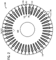
FIG. 2 , a cross-sectional view ofelectric machine 100 along line 2-2 ofFIG. 1 is shown according to an example of the disclosure.Electric machine 100 includes a plurality ofrotor bars 106 extending through a core material 108 (i.e., a rotor bar housing) ofelectric machine 100, where each rotor bar of the plurality ofrotor bars 106 includes at least a firstmetallic material 110 and a secondmetallic material 112. Firstmetallic material 110 has a first electrical resistivity, and secondmetallic material 112 has a second electrical resistivity greater than the first electrical resistivity. It is noted that eachrotor bar 106 includes anupper portion 114 and alower portion 116. - According to an example of the disclosure, first
metallic material 110 includes a copper material (e.g., a copper bar) and/or a silver material while secondmetallic material 112 includes an aluminum material. It is envisioned, however, that firstmetallic material 110 may be constructed of a material other than copper or silver. For example, firstmetallic material 110 may be constructed of a first type of aluminum having a corresponding first electrical resistivity, and secondmetallic material 112 may be constructed of a second type of aluminum having a corresponding second electrical resistivity different from the first electrical resistivity. According to such an example, the first type of aluminum of firstmetallic material 110 would have an electrical resistivity less than that of the second type of aluminum of secondmetallic material 112. It is noted that secondmetallic material 112 may be constructed of a material other than aluminum. - According to the example depicted in
FIG. 2 , secondmetallic material 112 is a material cast about firstmetallic material 110. - The running efficiency of
electric machine 100 is generally more influenced bylower portion 116 of eachrotor bar 106. As electrical resistivity oflower portion 116 decreases, the running efficiency ofelectric machine 100 increases. - Further, starting torque of
electric machine portion 100 may be influenced byupper portion 114 of eachrotor bar 106. For example, as the electrical resistivity ofupper portion 114 increases, so may the starting torque. Such a scenario can arise when, for example, the electrical excitation is from a fixed frequency source such as line-starting from an AC 60 Hz source. - Examples of the disclosure aid in maximizing or at least increasing the running efficiency of an electric machine (e.g., electric machine 100). Examples of the disclosure may also aid in increasing starting torque of an electric machine and/or limiting starting current of an electric machine. For example, the higher electrical resistivity of
upper portion 114, due to the higher electrical resistivity of secondmetallic material 112, may increase starting torque and/or limit starting current. Further, sincelower portion 116 includes firstmetallic material 110 having a lower electrical resistivity than secondmetallic material 112, the running efficiency of a corresponding electric machine (e.g., electric machine 100) increases. - Still referring to
FIG. 2 , secondmetallic material 112 may be chosen to maximize or increase starting torque and/or limit starting current, while firstmetallic material 110 can be chosen to maximize or increase running efficiency. Again, the higher electrical resistivity ofupper portion 114, due to secondmetallic material 112, may have a positive effect on the starting torque or starting current ofelectric machine 100, whilelower portion 116, due to the lower electrical resistivity of firstmetallic material 110 oflower portion 116, has a positive effect on the running efficiency ofelectric machine 100. - As discussed above, it is contemplated that
second material 112 may be cast aboutfirst material 110. It is envisioned, however, thatupper portion 114 ofrotor bar 106 may be a preformed component. In such an example, the preformed component may be constructed of the same material assecond material 112, or it may be constructed of another material. In either case, the preformed component has an electrical resistivity higher than the electrical resistivity offirst material 110. - It is also noted that examples of the disclosure may be employed to take advantage of the benefits of using high electrical resistivity rotor bars while reducing or limiting the manufacturing costs associated therewith. As would be appreciated by those skilled in the art, it is typically more expensive to manufacture an electric machine employing rotor bars made entirely of copper than to manufacture an electric machine that employs rotor bars made entirely of aluminum (i.e., a rotor bar typically having a higher electrical resistivity than a copper rotor bar). Such manufacturing cost differentials can be associated with the higher melting point of copper, which can necessitate more expensive tool and manufacturing processes. For example, it is often more expensive to cast copper than it is to cast aluminum.
- According to examples of the disclosure, however, manufacturing costs of rotor bars that take advantage of the benefits of using materials with lower electrical resistivity such as copper can be minimized. For example, first
metallic material 110 may be a pre-purchased copper bar either having the appropriate dimensions or may be machined to have the appropriate dimension, whereas secondmetallic material 112 may be cast about firstmetallic material 110. Accordingly, the need to cast firstmetallic material 110 may be avoided. -
FIGS. 3-5 illustrate a portion ofelectric machine 100 along line 5-5 ofFIG. 2 and show an example of manufacturing a rotor bar according to an example of the disclosure. - In
FIG. 3 , anopening 118 in rotor core orhousing 108 for insertion and casting of the rotor bar components is shown. InFIG. 4 , opening 118 is shown with a firstmetallic material 110 inserted therein. It is contemplated that firstmetallic material 110 may be a bar or bar-like material. As shown, it is contemplated that firstmetallic material 110 may have an interveningmaterial 120 thereon. Interveningmaterial 120 may be a cladding (e.g., an aluminum, nickel, or other type of cladding). It is also contemplated that interveningmaterial 120 may be an insulating material. It is noted, however, that examples free of an intervening material are also contemplated. Further details regarding interveningmaterial 120 will be set forth below with respect toFIG. 5 . -
FIG. 5 illustrates that cast material 112 (i.e., second metallic material) fills the remaining void ofopening 118 and is cast about firstmetallic material 110 and about interveningmaterial 120 if present. If present, interveningmaterial 120 may be an electrical insulator configured to at least partially electrically isolatecast material 112 fromfirst material 110. In addition, or alternatively, interveningmaterial 120 may be a cladding (e.g., an aluminum cladding) configured to enhance adhesion or coupling betweenfirst material 110 and castmaterial 112. As explained above with respect toFIG. 4 , examples free of interveningmaterial 120 are contemplated. Accordingly, with or without interveningmaterial 120 shown inFIG. 5 , castmaterial 112 about firstmetallic material 110forms rotor bar 106. - It is noted that cast
material 112 ofrotor bar 106 need not entirely coverfirst material 110. For example, as depicted in the example ofFIG. 4 , abottom portion 122 offirst material 110/interveningmaterial 120 combination is adjacent torotor core 108 withoutcast material 112 therebetween. Accordingly, castingmaterial 112 can either fully or partially surroundfirst material insert 110 depending on the location offirst material 110 withinopening 118. - As shown in
FIG. 5 ,rotor bar 106 includesupper portion 114 andlower portion 116. Firstmetallic material 110 has a lower electrical resistance thancast material 112. Accordingly, the effective electrical resistance oflower portion 116 is lower than the effective electrical resistance ofupper portion 114. Due to the lower effective electrical resistance oflower portion 116,electric machine 100 will have a higher running efficiency than a comparable electric machine (not shown) that employs rotor bars containing only castmaterial 112. - Further, since
cast material 112 inupper portion 114 has a higher electrical resistance than firstmetallic material 110,electric machine 100 may have a higher starting torque than a comparable machine (not shown) that employs rotor bars containing only the material employed for first metallic material 110 (e.g., copper). Further, the configuration ofrotor bar 106 may also be beneficial in limiting starting current. - Due to the bi-metallic nature of
rotor bar 106,electric machine 100 may benefit from the higher electrical resistance properties ofcast material 112 while also benefiting from the lower electrical resistance properties of firstmetallic material 110 - Referring now to
FIG. 6 , an exploded view of a portion ofelectric machine 100 ofFIG. 1 is shown according to an example of the disclosure. It is noted thatfins 104 ofFIG. 1 are not shown. As shown inFIG. 6 ,electric machine 100 includes a first coupling component 124 (i.e., a first ring),rotor core 108 havingopenings 118 therein, and a second coupling component 126 (i.e., a second ring). The plurality of rotor bars 106 are also shown in an exploded view, where eachrotor bar 106 includes a firstmetallic material 110 and a secondmetallic material 112. It is noted that secondmetallic material 112 is shown as two components (i.e., one component next tofirst ring 124 and another component next to second ring 126) for illustrative purposes. According to examples where secondmetallic material 112 is cast about firstmetallic material 110, secondmetallic material 112 is one component. - Though not shown, it is contemplated that first
metallic material 110 may have an intervening material (e.g., interveningmaterial 120 ofFIGS. 4-5 ) coupled thereto. If the intervening material is an insulator, first andsecond coupling components metallic material 110 and first andsecond coupling components metallic material 112. - As explained above with respect to
FIGS. 2-5 , according to examples of the disclosure, firstmetallic material 110 has a lower electrical resistance than secondmetallic material 112. Firstmetallic material 110 may be a bar or bar-like material, which is placed in anopening 118. According to an example, once eachmetallic material 110 is placed in eachopening 118, first andsecond coupling components second coupling components FIG. 6 , other shapes are contemplated. - Still referring to
FIG. 6 , secondmetallic material 112 may be cast around firstmetallic material 110 intoopening 118. As such, the manufacturing costs associated with casting firstmetallic material 110 may be avoided since firstmetallic material 110 need not be cast. According to the examples depicted inFIGS. 1 and6 , secondmetallic material 112 is also cast about first andsecond coupling components - Referring now to
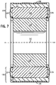
FIG. 7 , a cross-sectional view ofelectric machine 100 along line 7-7 ofFIG. 1 is shown according to an example of the disclosure. Afirst rotor bar 128 and asecond rotor bar 130 are shown inFIG. 7 , where eachrotor bar metallic material 110 and a secondmetallic material 112. Also shown inFIG. 7 are first ring 124 (i.e., a first coupling component) and second ring 126 (i.e., a second coupling component), where eachring electric machine 100. It is contemplated that first andsecond rings first material 110 to enable or enhance the electric coupling therebetween. - It is noted that the example of
electric machine 100 shown inFIG. 7 does not include cooling fins (e.g., coolingfins 104 ofFIG. 1 ). However, as suggested in the description ofFIG. 1 , examples of an electric machine, such aselectric machine 100, having cooling fins are contemplated. -
FIGS. 8-10 show steps for securing firstmetallic material 110 tofirst ring 124 andsecond ring 126 prior to the casting of secondmetallic material 112 thereabout according to an example of the disclosure. - In
FIG. 8 , acompression tool 132 is aligned with afirst end 134 and asecond end 136 of firstmetallic material 110. InFIG. 9 ,compression tool 132 applies pressure to first and second ends 134, 136, thus deforming first and second ends 134, 136 such that they overlap a portion of afirst ring 124 and a portion of asecond ring 126, respectively. As shown inFIG. 10 ,compression tool 132 is removed from deformed first and second ends 134, 136, thus leaving alow resistance contact 138 formed between firstmetallic material 110 and first andsecond rings low resistance contacts 138 thus formed ensure that first andsecond rings rotor bars 106 together as described above. -
FIGS. 11-12 show steps for securing firstmetallic material 110 tofirst ring 124 andsecond ring 126 prior to the casting of secondmetallic material 112 thereabout according to another example of the disclosure. - In
FIG. 11 , afirst screw cap 140 is aligned with afirst end 142 of a firstmetallic material 110, which has afirst cavity 144 formed therein, and asecond screw cap 146 is aligned with asecond end 148 of firstmetallic material 110, which has asecond cavity 150 formed therein. InFIG. 12 , first andsecond screw caps second cavities metallic material 110, thus causing firstmetallic material 110 to overlapfirst ring 124 andsecond ring 126. As such, alow resistance contact 152 is formed between firstmetallic material 110 and first andsecond rings low resistance contacts 152 thus formed ensure that first andsecond rings rotor bars 106 together as described above. - According to one example, second
metallic material 112 is cast around firstmetallic material 110 and first andsecond rings second screw caps metallic material 110. In this manner, secondmetallic material 112 is cast around first andsecond screw caps second screw caps -
FIGS. 13-15 show steps for securing firstmetallic material 110 tofirst ring 124 andsecond ring 126 prior to the casting of secondmetallic material 112 thereabout according to another example of the disclosure. - In
FIG. 13 , afirst washer 154 is aligned with afirst end 156 of firstmetallic material 110, and asecond washer 158 is aligned with asecond end 160 of firstmetallic material 110 oppositefirst end 156. InFIG. 14 ,first washer 154 is positioned aboutfirst end 156, andsecond washer 158 is positioned aboutsecond end 160. In addition, afirst screw cap 162 is aligned withfirst end 156 offirst material 110, which has afirst cavity 164 formed therein, and asecond screw cap 166 is aligned withsecond end 160 offirst material 110, which has asecond cavity 168 formed therein. As shown inFIG. 15 ,first screw cap 162 is coupled tofirst end 156 andsecond screw cap 166 is coupled tosecond end 160. As such, firstmetallic material 110 makes alow resistance contact 170 withfirst ring 124 viafirst screw cap 162 andfirst washer 154 and withsecond ring 126 viasecond screw cap 166 andsecond washer 158. - Therefore, according to one example of the disclosure, an electric machine includes a plurality of rotor bars and a first coupling component configured to electrically couple the plurality of rotor bars together. Each rotor bar of the plurality of rotor bars includes a first metallic material having a first electrical resistivity and a second metallic material cast about the first material, where the second metallic material has a second electrical resistivity greater than the first electrical resistivity. The first metallic material has a first end and a second end opposite the first end and the first coupling component is coupled to the first end of the first metallic material.
- According to another example of the disclosure, a method of manufacturing an electric machine includes inserting a plurality of bars into a rotor bar housing and electrically coupling the plurality of bars together, where each bar of the plurality of bars includes a first metallic material having a first electrical resistivity. The method also includes casting a second metallic material about the plurality of bars inserted into the rotor bar housing, where the second metallic material has a second electrical resistivity greater than the first electrical resistivity.
- According to another example of the disclosure, an electric machine includes a plurality of rotor bars and a first electrical coupling ring configured to electrically couple each rotor bar of the plurality of rotor bars together. Each rotor bar of the plurality of rotor bars includes a metallic bar and a metallic covering surrounding at least a majority of the metallic bar. Each metallic bar includes a first material having a first electrical resistivity and each metallic covering has a second electrical resistivity greater than the first electrical resistivity.
Claims (11)
- An electric machine (100) comprising:a plurality of rotor bars (106, 128, 130) in a rotor core (108);a first ring (124) configured to electrically couple the plurality of rotor bars (106, 128, 130) together; anda second ring (126) configured to electrically couple the plurality of rotor bars (106, 128, 130) together;wherein each rotor bar (106, 128, 130) of the plurality of rotor bars (106, 128, 130) includes an upper portion (114) and a lower portion (116) that is opposite the upper portion and towards the rotor core (108) and comprises:a first metallic material (110) having a first electrical resistivity, the first metallic material (110) having a first end (142) and a second end (148) opposite the first end (142), wherein the first ring (124) is coupled to the first end (142) of the first metallic material (110) and the second ring (126) is coupled to the second end (148) of the first metallic material (110);a second metallic material (112) cast about the first material (110) and having a second electrical resistivity greater than the first electrical resistivity,wherein the lower portion (116) includes the first metallic material (110) and the second metallic material (112), and the upper portion (114) includes only the second metallic material (112);wherein:the first ring (124) is electrically coupled to the first end (142) of the first metallic material (110) ;the second ring (126) is electrically coupled to the second end (148) of the first metallic material (110);a first screw cap (140) is aligned and screwed to the first end (142) of the first metallic material (110), the first end (142) having a first cavity (144) formed therein, the first screw cap (140) being screwed into the first cavity (144);a second screw cap (146) is aligned and screwed to the second end (148) of the first metallic material (110) opposite the first end (142) of the first metallic material (110), the second end (148) having a second cavity (150) formed therein, the second screw cap (146) being screwed into the second cavity (150); andthe first screw cap (140) is screwed into the first cavity to cause the first metallic material to overlap the first ring (124) so as to couple the first ring (124) to the first end (142) of the first metallic material (110), and the second screw cap (146) is screwed into the second cavity to cause the first metallic material to overlap the second ring (126) so as to couple the second ring (126) to the second end (148) of the first metallic material (110).
- The electric machine (100) of claim 1 wherein the first metallic material (110) comprises a copper bar and the second metallic material (112) comprises aluminum.
- The electric machine (100) of claim 1 wherein the second metallic material (112) is also cast about portions of the first and second rings (124, 126).
- The electric machine (100) of claim 3 wherein each rotor bar of the plurality of rotor bars (106, 128, 130) further comprises an intervening material (120) between the first and second metallic materials (110, 112), wherein the intervening material (120) is configured to aid in an adhesion of the second metallic material (112) to the first metallic material (110).
- The electric machine (100) of claim 4 wherein the intervening material (120) comprises an aluminum cladding over the first metallic material (110).
- The electric machine (100) of claim 3 further comprising an intervening material (120) coupled to the first material (110) of each rotor (106, 128, 130) and to the first and second rings (124, 126), and wherein the intervening material (120) is configured to at least partially electrically isolate the first metallic material (110) of each rotor bar (106, 128, 130) and the first and second rings (124, 126) from the second material (112) of each rotor bar (106, 128, 130).
- The electric machine (100) of claim 1 wherein the first metallic material (110) comprises nickel.
- A method of manufacturing an electric machine comprising:providing a rotor core (108);inserting a plurality of rotor bars (106, 128, 130) into a rotor bar housing, wherein each of the plurality of rotor bars (106, 128, 130) includes an upper portion (114) and a lower portion (116) and comprises a first metallic material (110) having a first electrical resistivity, the first metallic material (110) having a first end (142) and a second end (148) opposite the first end (142);arranging each of the plurality of rotor bars (106, 128, 130) with upper portion (114) and the lower portion (116) opposite the upper portion (114) towards the rotor core (108);electrically coupling the plurality of rotor bars (106, 128, 130) together using a first ring (124) and a second ring (126);casting a second metallic material (112) about the plurality of bars (106, 128, 130) inserted into the rotor bar housing so that the first metallic material (110) and the second metallic material (112) are included in the lower portion (116), and only the second metallic material (112) is included in the upper portion (114), wherein the second metallic material (112) has a second electrical resistivity greater than the first electrical resistivity;coupling the first ring (124) to the first end (142) of the first metallic material (110) and coupling the second ring (126) to the second end (148)) of the first metallic material (110);forming a first cavity (144) in a first end (142) of the first metallic material (110);aligning and screwing a first screw cap (140) to the first end (142) of the first metallic material (110), the first screw cap (140) being screwed into the first cavity (144);forming a second cavity (150) in the second end (148) of the first metallic material (110); andaligning and screwing a second screw cap (146) to the second end (148) of the first metallic material (110), the second screw cap (146) being screwed into the second cavity (150);wherein the first screw cap (140) is screwed into the first cavity to cause the first metallic material (110) to overlap the first ring (124) so as to couple the first ring (124) to the first end (142) of the first metallic material (110), and the second screw cap (146) is screwed into the second cavity to cause the first metallic material (110) to overlap the second ring (126) so as to couple the second ring (126) to the second end (148) of the first metallic material (110).
- The method of claim 8, further comprising coupling an electrical insulator to each bar (106, 128, 130) of the plurality of bars (106, 128, 130).
- The method of claim 8 or claim 9, further comprising cladding each of the plurality of bars (106, 128, 130) with a metallic cladding material.
- The method of any of claims 8 to 10, wherein the cladding material comprises aluminum.
Applications Claiming Priority (1)
| Application Number | Priority Date | Filing Date | Title |
|---|---|---|---|
| US12/789,580 US8274190B2 (en) | 2010-05-28 | 2010-05-28 | Electric machine rotor bar and method of making same |
Publications (3)
| Publication Number | Publication Date |
|---|---|
| EP2390987A2 EP2390987A2 (en) | 2011-11-30 |
| EP2390987A3 EP2390987A3 (en) | 2017-03-29 |
| EP2390987B1 true EP2390987B1 (en) | 2022-05-04 |
Family
ID=44741765
Family Applications (1)
| Application Number | Title | Priority Date | Filing Date |
|---|---|---|---|
| EP11167545.0A Active EP2390987B1 (en) | 2010-05-28 | 2011-05-25 | Electric machine rotor bar and method of making same |
Country Status (4)
| Country | Link |
|---|---|
| US (2) | US8274190B2 (en) |
| EP (1) | EP2390987B1 (en) |
| JP (2) | JP5997880B2 (en) |
| CN (1) | CN102263466B (en) |
Families Citing this family (41)
| Publication number | Priority date | Publication date | Assignee | Title |
|---|---|---|---|---|
| JP4626683B2 (en) * | 2007-08-29 | 2011-02-09 | トヨタ自動車株式会社 | Steel material having nonmagnetic portion, method for manufacturing the same, and rotating electric machine core |
| EP2288004B1 (en) * | 2009-08-19 | 2017-05-17 | Siemens Aktiengesellschaft | Cage rotor with start-up rod |
| JP5490251B2 (en) * | 2010-10-19 | 2014-05-14 | 三菱電機株式会社 | Induction motor rotor, induction motor, compressor, blower and air conditioner |
| EP2592729B1 (en) * | 2011-11-09 | 2018-05-02 | Siemens Aktiengesellschaft | Rotor of an asynchronous machine with holding element |
| US9154008B2 (en) * | 2012-10-02 | 2015-10-06 | Siemens Industry, Inc. | Hybrid rotor bar assemblies, electric motors including hybrid rotor bar assemblies, and methods of assemblying same |
| US20140154115A1 (en) * | 2012-11-30 | 2014-06-05 | Emerson Electric Co. | Scroll Compressor Having A Single Phase Induction Motor With Aluminum Windings |
| US9935513B2 (en) * | 2013-04-22 | 2018-04-03 | Mitsubishi Electric Corporation | Rotating electrical machine |
| EP2800255A1 (en) * | 2013-04-29 | 2014-11-05 | Siemens Aktiengesellschaft | Production of a rotor of an electric asynchronous machine |
| CN105284038B (en) * | 2013-07-01 | 2018-04-10 | 株式会社日立产机系统 | Electric rotating machine and its manufacture method |
| TWI504105B (en) * | 2013-12-25 | 2015-10-11 | Teco Elec & Machinery Co Ltd | A rotor structure applied to motor and manufacture method thereof |
| TWI504104B (en) * | 2013-12-25 | 2015-10-11 | Teco Elec & Machinery Co Ltd | A rotor structure applied to motor and manufacture method thereof |
| CN104795911A (en) * | 2014-01-17 | 2015-07-22 | 东元电机股份有限公司 | Rotor structure of motor and manufacturing method thereof |
| CN104795912A (en) * | 2014-01-17 | 2015-07-22 | 东元电机股份有限公司 | Rotor structure applied to motor and manufacturing method thereof |
| DE102014210339A1 (en) * | 2014-06-02 | 2015-12-03 | Siemens Aktiengesellschaft | Squirrel cage of an asynchronous machine |
| CN105703499A (en) * | 2014-11-26 | 2016-06-22 | 东元电机股份有限公司 | Rotor structure with escape sheet and manufacturing method thereof |
| US20160359399A1 (en) * | 2015-06-03 | 2016-12-08 | Electro-Motive Diesel, Inc. | Hybrid Traction Motor Rotors for Diesel-Electric Locomotives |
| TWI614974B (en) | 2015-12-03 | 2018-02-11 | 財團法人工業技術研究院 | Rotor of electric motor |
| CN106849575A (en) * | 2017-02-24 | 2017-06-13 | 康富科技股份有限公司 | A kind of motor rotor |
| US10630151B2 (en) * | 2017-06-29 | 2020-04-21 | GM Global Technology Operations LLC | Rotor for an induction motor |
| KR101878677B1 (en) * | 2017-06-29 | 2018-07-16 | 엘지전자 주식회사 | Rotor for electric motor |
| FR3069732B1 (en) | 2017-07-31 | 2021-02-12 | Leroy Somer Moteurs | INJECTED CAGE ROTOR |
| FR3069725B1 (en) | 2017-07-31 | 2021-01-29 | Leroy Somer Moteurs | INJECTED CAGE ROTOR |
| FR3069734B1 (en) | 2017-07-31 | 2022-12-30 | Leroy Somer Moteurs | INJECTED CAGE ROTOR |
| FR3069735B1 (en) | 2017-07-31 | 2023-01-20 | Leroy Somer Moteurs | INJECTED CAGE ROTOR |
| FR3069730B1 (en) | 2017-07-31 | 2021-08-20 | Leroy Somer Moteurs | INJECTED CAGE ROTOR |
| FR3069731B1 (en) | 2017-07-31 | 2021-12-24 | Leroy Somer Moteurs | INJECTED CAGE ROTOR |
| FR3069733B1 (en) | 2017-07-31 | 2023-05-05 | Leroy Somer Moteurs | INJECTED CAGE ROTOR |
| FR3069727B1 (en) | 2017-07-31 | 2021-02-12 | Leroy Somer Moteurs | INJECTED CAGE ROTOR |
| FR3069726B1 (en) | 2017-07-31 | 2020-12-11 | Leroy Somer Moteurs | INJECTED CAGE ROTOR |
| FR3069728B1 (en) * | 2017-07-31 | 2020-10-02 | Leroy Somer Moteurs | INJECTED CAGE ROTOR |
| CN107591916B (en) * | 2017-10-28 | 2023-05-30 | 德力电机有限公司 | A cast copper rotor of an electric motor and its processing technology |
| TWI649941B (en) | 2017-11-03 | 2019-02-01 | 財團法人工業技術研究院 | Rotor mechanism and method for manufacturing the same |
| US10601288B2 (en) * | 2017-11-17 | 2020-03-24 | Hamilton Sundstrand Corporation | Additive amortisseur circuit |
| WO2019176107A1 (en) * | 2018-03-16 | 2019-09-19 | 三菱電機株式会社 | Induction motor rotor and induction motor |
| EP3588753B1 (en) * | 2018-06-29 | 2021-04-21 | ABB Schweiz AG | An electric induction machine |
| DE102018008347A1 (en) * | 2018-10-23 | 2020-04-23 | Wieland-Werke Ag | Short-circuit rotor |
| KR102220618B1 (en) * | 2019-03-27 | 2021-02-26 | 한국전자기술연구원 | Hybrid induction motor rotor and motor using the same |
| US11522427B2 (en) | 2020-08-28 | 2022-12-06 | Emerson Electric Co. | Single phase induction motors including aluminum windings and high permeability low coreloss steel |
| CN116711193A (en) * | 2020-12-11 | 2023-09-05 | Weg电力设备公司 | Rotor for rotating electric machine, manufacturing method and corresponding rotating electric machine |
| EP4436015A1 (en) * | 2023-03-21 | 2024-09-25 | Innomotics GmbH | Rotor of a squirrel-cage motor, squirrel-cage motor having a rotor, and method for producing a rotor of a squirrel-cage motor |
| KR20240145202A (en) * | 2023-03-27 | 2024-10-07 | 현대자동차주식회사 | Rotor for induction motor and method for manufacturing thereof |
Family Cites Families (49)
| Publication number | Priority date | Publication date | Assignee | Title |
|---|---|---|---|---|
| US1524558A (en) * | 1922-10-28 | 1925-01-27 | Westinghouse Electric & Mfg Co | Insulation for conductors in squirrel-cage motors |
| US1936244A (en) * | 1927-02-11 | 1933-11-21 | B F Sturtevant Co | Laminated core member and method of making the same |
| US2048421A (en) * | 1935-08-30 | 1936-07-21 | Solar Ind Inc | Rotor |
| US2350012A (en) * | 1942-05-13 | 1944-05-30 | Singer Mfg Co | Electrical rotor core |
| US2784333A (en) * | 1953-08-03 | 1957-03-05 | Reliance Electric & Eng Co | Cast rotor and method |
| US2857539A (en) * | 1957-04-15 | 1958-10-21 | Smith Corp A O | Induction motors |
| US2991378A (en) * | 1958-01-02 | 1961-07-04 | Gen Electric | Composite magnetic core structure and method of making same |
| JPS55127868A (en) * | 1979-03-22 | 1980-10-03 | Mitsubishi Electric Corp | Manufacture of rotor of rotating electric machine |
| US4644210A (en) * | 1985-12-12 | 1987-02-17 | Rockwell International Corporation | High speed induction motor with squirrel cage rotor |
| JPH01126157A (en) * | 1987-11-06 | 1989-05-18 | Mitsubishi Electric Corp | Rotor of superconductive rotary electric machine |
| JPH0716297B2 (en) * | 1987-11-27 | 1995-02-22 | 三菱電機株式会社 | Electric motor |
| JPH01252144A (en) * | 1987-12-11 | 1989-10-06 | Shinko Electric Co Ltd | Rotor for squirrel-cage induction motor and manufacture thereof |
| US5182483A (en) * | 1989-12-28 | 1993-01-26 | Kabushiki Kaisha Toshiba | Squirrel-cage rotor with shaped-conductor harmonic reduction |
| JPH05247501A (en) | 1992-03-06 | 1993-09-24 | Toshiba Corp | Conductive material and method for manufacturing the same, and basket type induction machine using the conductive material |
| EP0608675B1 (en) * | 1993-01-26 | 1995-09-13 | Gec Alsthom Acec Energie S.A. | High rotating speed, high power electrical motor |
| DE4308683A1 (en) * | 1993-03-18 | 1994-09-22 | Siemens Ag | Squirrel-cage rotor for an asynchronous machine |
| GB2277205B (en) * | 1993-04-01 | 1996-04-10 | Gec Alsthom Ltd | Rotating electrical machines |
| JPH0819230A (en) * | 1994-06-24 | 1996-01-19 | Hitachi Koki Co Ltd | High frequency motor |
| JPH08223878A (en) * | 1995-02-09 | 1996-08-30 | Hitachi Ltd | Induction motor |
| JPH0974726A (en) * | 1995-09-07 | 1997-03-18 | Hitachi Ltd | Induction motor manufacturing method |
| JPH09266647A (en) * | 1996-03-27 | 1997-10-07 | Toyota Autom Loom Works Ltd | Rotor structure of motor |
| JPH09268647A (en) | 1996-03-28 | 1997-10-14 | Natl House Ind Co Ltd | Structure of building |
| US5793145A (en) * | 1996-05-02 | 1998-08-11 | Chrysler Corporation | End cap to rotor attachment |
| JPH1028360A (en) * | 1996-07-11 | 1998-01-27 | Hitachi Ltd | Induction motor and its rotor |
| US5990595A (en) | 1996-10-04 | 1999-11-23 | General Electric Company | Rotors and methods of manufacturing such rotors |
| JPH10234166A (en) * | 1997-02-19 | 1998-09-02 | Hitachi Ltd | Induction motor rotor |
| US6088906A (en) * | 1997-09-16 | 2000-07-18 | Ut-Battelle, Llc | Method of manufacturing squirrel cage rotors |
| US6159305A (en) | 1998-07-14 | 2000-12-12 | General Electric Company | High speed induction motor rotor and method of fabrication |
| JP2000060045A (en) * | 1998-08-07 | 2000-02-25 | Matsushita Electric Ind Co Ltd | Induction motor rotor |
| US6246141B1 (en) * | 1999-04-23 | 2001-06-12 | Hamilton Sundstrand Corporation | High torque reduced starting current electric motor |
| US6092277A (en) | 1999-04-28 | 2000-07-25 | General Electric Company | Rotor bar swaging process |
| US7538458B2 (en) * | 2001-07-13 | 2009-05-26 | Voith Patent Gmbh | Construction and method of an electric motor drive |
| US7129613B2 (en) * | 2003-02-12 | 2006-10-31 | Hitachi, Ltd. | Rotating electrical machine and drive system of cage induction motor |
| JP2004248361A (en) * | 2003-02-12 | 2004-09-02 | Hitachi Ltd | Rotating electric machine and cage induction motor drive system |
| JP2004254433A (en) * | 2003-02-20 | 2004-09-09 | Yaskawa Electric Corp | Manufacturing method of cage rotor |
| JP2004304930A (en) * | 2003-03-31 | 2004-10-28 | Hitachi Ltd | A rotor for a cage-type induction motor and a method for manufacturing the rotor. |
| DE10345637A1 (en) * | 2003-09-29 | 2005-05-25 | Siemens Ag | Squirrel-cage |
| GB0323232D0 (en) * | 2003-10-03 | 2003-11-05 | Rolls Royce Plc | Electrical machine |
| US20050134137A1 (en) * | 2003-12-17 | 2005-06-23 | Sweo Edwin A. | Method for manufacturing squirrel cage rotor |
| JP2005278373A (en) * | 2004-03-26 | 2005-10-06 | Jatco Ltd | Rotor of induction motor |
| US6977459B1 (en) | 2004-05-26 | 2005-12-20 | General Electric Company | Apparatus and methods for anchoring a modular winding to a rotor in an electrical machine |
| CN2814785Y (en) * | 2005-04-18 | 2006-09-06 | 王胜五 | High starting torque big and medium squirrel cage asynchronous motor |
| US7451538B2 (en) * | 2005-09-20 | 2008-11-18 | Reliance Electric Technologies, Llc | Method for fabricating rotor assembly |
| US7504754B2 (en) | 2005-10-31 | 2009-03-17 | Caterpillar Inc. | Rotor having multiple permanent-magnet pieces in a cavity |
| JP4937632B2 (en) * | 2006-04-26 | 2012-05-23 | 三菱電機株式会社 | Induction motor rotor and method of manufacturing induction motor rotor |
| US7622817B2 (en) | 2006-12-13 | 2009-11-24 | General Electric Company | High-speed high-pole count generators |
| US7791237B2 (en) | 2006-12-19 | 2010-09-07 | General Electric Company | Fault-tolerant synchronous permanent magnet machine |
| US7851961B2 (en) * | 2007-09-20 | 2010-12-14 | Siemens Industry, Inc. | System and method with a rotor having parallel sided rotor bars |
| JP5019451B2 (en) * | 2007-11-15 | 2012-09-05 | 東芝産業機器製造株式会社 | Rotor |
-
2010
- 2010-05-28 US US12/789,580 patent/US8274190B2/en active Active
-
2011
- 2011-05-18 JP JP2011110894A patent/JP5997880B2/en active Active
- 2011-05-25 EP EP11167545.0A patent/EP2390987B1/en active Active
- 2011-05-27 CN CN201110161393.0A patent/CN102263466B/en active Active
-
2012
- 2012-07-23 US US13/555,363 patent/US9438077B2/en active Active
-
2015
- 2015-10-28 JP JP2015211574A patent/JP6106246B2/en active Active
Also Published As
| Publication number | Publication date |
|---|---|
| JP2016015887A (en) | 2016-01-28 |
| JP6106246B2 (en) | 2017-03-29 |
| EP2390987A3 (en) | 2017-03-29 |
| JP5997880B2 (en) | 2016-09-28 |
| US20120286618A1 (en) | 2012-11-15 |
| EP2390987A2 (en) | 2011-11-30 |
| CN102263466B (en) | 2016-01-06 |
| JP2011250677A (en) | 2011-12-08 |
| US9438077B2 (en) | 2016-09-06 |
| CN102263466A (en) | 2011-11-30 |
| US20110291516A1 (en) | 2011-12-01 |
| US8274190B2 (en) | 2012-09-25 |
Similar Documents
| Publication | Publication Date | Title |
|---|---|---|
| EP2390987B1 (en) | Electric machine rotor bar and method of making same | |
| US8729755B2 (en) | Intermediate connection member, stator and motor | |
| EP1593191B1 (en) | Stator coil module, method of manufacturing the same, and electric rotating machine | |
| US8220146B2 (en) | Method of manufacturing short-circuiting member | |
| JP5558961B2 (en) | Hermetic compressor | |
| EP2047581B1 (en) | Method of manufacturing a line start permanent magnet electric motor | |
| EP2620648B1 (en) | Motor-driven compressor and method for manufacturing the same | |
| JP5843980B2 (en) | Method for manufacturing cage rotor and method for manufacturing induction motor | |
| JP2008514173A (en) | Permanent magnet synchronous machine with rectangular wire winding | |
| US20060066157A1 (en) | Rotor for an induction device | |
| US7215056B2 (en) | Electrical machine | |
| EP2437379A2 (en) | Axial coil for a slotless electric motor | |
| KR20080058577A (en) | Rotor of squirrel cage induction motor | |
| US20190052135A1 (en) | Stator for rotary electric machine | |
| CN105164902B (en) | Rotor for motor | |
| CN101842944A (en) | Method for producing a commutator ring of a roller commutator of an electric machine, and electric machine | |
| CN107666226A (en) | Rotor and there is its motor, compressor and refrigeration plant | |
| KR20060095399A (en) | Squirrel rotor of induction motor | |
| KR20060094811A (en) | Rotor of induction motor and its manufacturing method | |
| CN108696023A (en) | Insulation framework, motor stator and motor | |
| JP2018082507A (en) | Commutator motor element, commutator motor, electric blower, vacuum cleaner, commutator motor element manufacturing method |
Legal Events
| Date | Code | Title | Description |
|---|---|---|---|
| AK | Designated contracting states |
Kind code of ref document: A2 Designated state(s): AL AT BE BG CH CY CZ DE DK EE ES FI FR GB GR HR HU IE IS IT LI LT LU LV MC MK MT NL NO PL PT RO RS SE SI SK SM TR |
|
| AX | Request for extension of the european patent |
Extension state: BA ME |
|
| PUAI | Public reference made under article 153(3) epc to a published international application that has entered the european phase |
Free format text: ORIGINAL CODE: 0009012 |
|
| PUAL | Search report despatched |
Free format text: ORIGINAL CODE: 0009013 |
|
| AK | Designated contracting states |
Kind code of ref document: A3 Designated state(s): AL AT BE BG CH CY CZ DE DK EE ES FI FR GB GR HR HU IE IS IT LI LT LU LV MC MK MT NL NO PL PT RO RS SE SI SK SM TR |
|
| AX | Request for extension of the european patent |
Extension state: BA ME |
|
| RIC1 | Information provided on ipc code assigned before grant |
Ipc: H02K 3/12 20060101AFI20170222BHEP Ipc: H02K 15/00 20060101ALI20170222BHEP Ipc: B22D 19/00 20060101ALI20170222BHEP |
|
| STAA | Information on the status of an ep patent application or granted ep patent |
Free format text: STATUS: REQUEST FOR EXAMINATION WAS MADE |
|
| 17P | Request for examination filed |
Effective date: 20170929 |
|
| RBV | Designated contracting states (corrected) |
Designated state(s): AL AT BE BG CH CY CZ DE DK EE ES FI FR GB GR HR HU IE IS IT LI LT LU LV MC MK MT NL NO PL PT RO RS SE SI SK SM TR |
|
| STAA | Information on the status of an ep patent application or granted ep patent |
Free format text: STATUS: EXAMINATION IS IN PROGRESS |
|
| 17Q | First examination report despatched |
Effective date: 20180316 |
|
| GRAP | Despatch of communication of intention to grant a patent |
Free format text: ORIGINAL CODE: EPIDOSNIGR1 |
|
| STAA | Information on the status of an ep patent application or granted ep patent |
Free format text: STATUS: GRANT OF PATENT IS INTENDED |
|
| INTG | Intention to grant announced |
Effective date: 20210604 |
|
| RIN1 | Information on inventor provided before grant (corrected) |
Inventor name: ALEXANDER, JAMES P. Inventor name: KING, ROBERT DEAN Inventor name: EL-REFAIE, AYMAN MOHAMED FAWZI |
|
| GRAJ | Information related to disapproval of communication of intention to grant by the applicant or resumption of examination proceedings by the epo deleted |
Free format text: ORIGINAL CODE: EPIDOSDIGR1 |
|
| STAA | Information on the status of an ep patent application or granted ep patent |
Free format text: STATUS: EXAMINATION IS IN PROGRESS |
|
| GRAP | Despatch of communication of intention to grant a patent |
Free format text: ORIGINAL CODE: EPIDOSNIGR1 |
|
| STAA | Information on the status of an ep patent application or granted ep patent |
Free format text: STATUS: GRANT OF PATENT IS INTENDED |
|
| INTC | Intention to grant announced (deleted) | ||
| INTG | Intention to grant announced |
Effective date: 20211008 |
|
| GRAJ | Information related to disapproval of communication of intention to grant by the applicant or resumption of examination proceedings by the epo deleted |
Free format text: ORIGINAL CODE: EPIDOSDIGR1 |
|
| STAA | Information on the status of an ep patent application or granted ep patent |
Free format text: STATUS: EXAMINATION IS IN PROGRESS |
|
| GRAP | Despatch of communication of intention to grant a patent |
Free format text: ORIGINAL CODE: EPIDOSNIGR1 |
|
| STAA | Information on the status of an ep patent application or granted ep patent |
Free format text: STATUS: GRANT OF PATENT IS INTENDED |
|
| INTC | Intention to grant announced (deleted) | ||
| INTG | Intention to grant announced |
Effective date: 20220225 |
|
| GRAS | Grant fee paid |
Free format text: ORIGINAL CODE: EPIDOSNIGR3 |
|
| GRAA | (expected) grant |
Free format text: ORIGINAL CODE: 0009210 |
|
| STAA | Information on the status of an ep patent application or granted ep patent |
Free format text: STATUS: THE PATENT HAS BEEN GRANTED |
|
| AK | Designated contracting states |
Kind code of ref document: B1 Designated state(s): AL AT BE BG CH CY CZ DE DK EE ES FI FR GB GR HR HU IE IS IT LI LT LU LV MC MK MT NL NO PL PT RO RS SE SI SK SM TR |
|
| REG | Reference to a national code |
Ref country code: GB Ref legal event code: FG4D |
|
| REG | Reference to a national code |
Ref country code: CH Ref legal event code: EP |
|
| REG | Reference to a national code |
Ref country code: AT Ref legal event code: REF Ref document number: 1490176 Country of ref document: AT Kind code of ref document: T Effective date: 20220515 |
|
| REG | Reference to a national code |
Ref country code: IE Ref legal event code: FG4D Ref country code: DE Ref legal event code: R096 Ref document number: 602011072836 Country of ref document: DE |
|
| REG | Reference to a national code |
Ref country code: LT Ref legal event code: MG9D |
|
| REG | Reference to a national code |
Ref country code: NL Ref legal event code: MP Effective date: 20220504 |
|
| REG | Reference to a national code |
Ref country code: AT Ref legal event code: MK05 Ref document number: 1490176 Country of ref document: AT Kind code of ref document: T Effective date: 20220504 |
|
| PG25 | Lapsed in a contracting state [announced via postgrant information from national office to epo] |
Ref country code: SE Free format text: LAPSE BECAUSE OF FAILURE TO SUBMIT A TRANSLATION OF THE DESCRIPTION OR TO PAY THE FEE WITHIN THE PRESCRIBED TIME-LIMIT Effective date: 20220504 Ref country code: PT Free format text: LAPSE BECAUSE OF FAILURE TO SUBMIT A TRANSLATION OF THE DESCRIPTION OR TO PAY THE FEE WITHIN THE PRESCRIBED TIME-LIMIT Effective date: 20220905 Ref country code: NO Free format text: LAPSE BECAUSE OF FAILURE TO SUBMIT A TRANSLATION OF THE DESCRIPTION OR TO PAY THE FEE WITHIN THE PRESCRIBED TIME-LIMIT Effective date: 20220804 Ref country code: NL Free format text: LAPSE BECAUSE OF FAILURE TO SUBMIT A TRANSLATION OF THE DESCRIPTION OR TO PAY THE FEE WITHIN THE PRESCRIBED TIME-LIMIT Effective date: 20220504 Ref country code: LT Free format text: LAPSE BECAUSE OF FAILURE TO SUBMIT A TRANSLATION OF THE DESCRIPTION OR TO PAY THE FEE WITHIN THE PRESCRIBED TIME-LIMIT Effective date: 20220504 Ref country code: HR Free format text: LAPSE BECAUSE OF FAILURE TO SUBMIT A TRANSLATION OF THE DESCRIPTION OR TO PAY THE FEE WITHIN THE PRESCRIBED TIME-LIMIT Effective date: 20220504 Ref country code: GR Free format text: LAPSE BECAUSE OF FAILURE TO SUBMIT A TRANSLATION OF THE DESCRIPTION OR TO PAY THE FEE WITHIN THE PRESCRIBED TIME-LIMIT Effective date: 20220805 Ref country code: FI Free format text: LAPSE BECAUSE OF FAILURE TO SUBMIT A TRANSLATION OF THE DESCRIPTION OR TO PAY THE FEE WITHIN THE PRESCRIBED TIME-LIMIT Effective date: 20220504 Ref country code: ES Free format text: LAPSE BECAUSE OF FAILURE TO SUBMIT A TRANSLATION OF THE DESCRIPTION OR TO PAY THE FEE WITHIN THE PRESCRIBED TIME-LIMIT Effective date: 20220504 Ref country code: BG Free format text: LAPSE BECAUSE OF FAILURE TO SUBMIT A TRANSLATION OF THE DESCRIPTION OR TO PAY THE FEE WITHIN THE PRESCRIBED TIME-LIMIT Effective date: 20220804 Ref country code: AT Free format text: LAPSE BECAUSE OF FAILURE TO SUBMIT A TRANSLATION OF THE DESCRIPTION OR TO PAY THE FEE WITHIN THE PRESCRIBED TIME-LIMIT Effective date: 20220504 |
|
| PG25 | Lapsed in a contracting state [announced via postgrant information from national office to epo] |
Ref country code: RS Free format text: LAPSE BECAUSE OF FAILURE TO SUBMIT A TRANSLATION OF THE DESCRIPTION OR TO PAY THE FEE WITHIN THE PRESCRIBED TIME-LIMIT Effective date: 20220504 Ref country code: PL Free format text: LAPSE BECAUSE OF FAILURE TO SUBMIT A TRANSLATION OF THE DESCRIPTION OR TO PAY THE FEE WITHIN THE PRESCRIBED TIME-LIMIT Effective date: 20220504 Ref country code: LV Free format text: LAPSE BECAUSE OF FAILURE TO SUBMIT A TRANSLATION OF THE DESCRIPTION OR TO PAY THE FEE WITHIN THE PRESCRIBED TIME-LIMIT Effective date: 20220504 Ref country code: IS Free format text: LAPSE BECAUSE OF FAILURE TO SUBMIT A TRANSLATION OF THE DESCRIPTION OR TO PAY THE FEE WITHIN THE PRESCRIBED TIME-LIMIT Effective date: 20220904 |
|
| REG | Reference to a national code |
Ref country code: CH Ref legal event code: PL |
|
| REG | Reference to a national code |
Ref country code: BE Ref legal event code: MM Effective date: 20220531 |
|
| PG25 | Lapsed in a contracting state [announced via postgrant information from national office to epo] |
Ref country code: SM Free format text: LAPSE BECAUSE OF FAILURE TO SUBMIT A TRANSLATION OF THE DESCRIPTION OR TO PAY THE FEE WITHIN THE PRESCRIBED TIME-LIMIT Effective date: 20220504 Ref country code: SK Free format text: LAPSE BECAUSE OF FAILURE TO SUBMIT A TRANSLATION OF THE DESCRIPTION OR TO PAY THE FEE WITHIN THE PRESCRIBED TIME-LIMIT Effective date: 20220504 Ref country code: RO Free format text: LAPSE BECAUSE OF FAILURE TO SUBMIT A TRANSLATION OF THE DESCRIPTION OR TO PAY THE FEE WITHIN THE PRESCRIBED TIME-LIMIT Effective date: 20220504 Ref country code: LU Free format text: LAPSE BECAUSE OF NON-PAYMENT OF DUE FEES Effective date: 20220525 Ref country code: LI Free format text: LAPSE BECAUSE OF NON-PAYMENT OF DUE FEES Effective date: 20220531 Ref country code: EE Free format text: LAPSE BECAUSE OF FAILURE TO SUBMIT A TRANSLATION OF THE DESCRIPTION OR TO PAY THE FEE WITHIN THE PRESCRIBED TIME-LIMIT Effective date: 20220504 Ref country code: DK Free format text: LAPSE BECAUSE OF FAILURE TO SUBMIT A TRANSLATION OF THE DESCRIPTION OR TO PAY THE FEE WITHIN THE PRESCRIBED TIME-LIMIT Effective date: 20220504 Ref country code: CZ Free format text: LAPSE BECAUSE OF FAILURE TO SUBMIT A TRANSLATION OF THE DESCRIPTION OR TO PAY THE FEE WITHIN THE PRESCRIBED TIME-LIMIT Effective date: 20220504 Ref country code: CH Free format text: LAPSE BECAUSE OF NON-PAYMENT OF DUE FEES Effective date: 20220531 |
|
| REG | Reference to a national code |
Ref country code: DE Ref legal event code: R097 Ref document number: 602011072836 Country of ref document: DE |
|
| PG25 | Lapsed in a contracting state [announced via postgrant information from national office to epo] |
Ref country code: MC Free format text: LAPSE BECAUSE OF FAILURE TO SUBMIT A TRANSLATION OF THE DESCRIPTION OR TO PAY THE FEE WITHIN THE PRESCRIBED TIME-LIMIT Effective date: 20220504 |
|
| PLBE | No opposition filed within time limit |
Free format text: ORIGINAL CODE: 0009261 |
|
| STAA | Information on the status of an ep patent application or granted ep patent |
Free format text: STATUS: NO OPPOSITION FILED WITHIN TIME LIMIT |
|
| PG25 | Lapsed in a contracting state [announced via postgrant information from national office to epo] |
Ref country code: AL Free format text: LAPSE BECAUSE OF FAILURE TO SUBMIT A TRANSLATION OF THE DESCRIPTION OR TO PAY THE FEE WITHIN THE PRESCRIBED TIME-LIMIT Effective date: 20220504 |
|
| 26N | No opposition filed |
Effective date: 20230207 |
|
| GBPC | Gb: european patent ceased through non-payment of renewal fee |
Effective date: 20220804 |
|
| PG25 | Lapsed in a contracting state [announced via postgrant information from national office to epo] |
Ref country code: IE Free format text: LAPSE BECAUSE OF NON-PAYMENT OF DUE FEES Effective date: 20220525 Ref country code: FR Free format text: LAPSE BECAUSE OF NON-PAYMENT OF DUE FEES Effective date: 20220704 |
|
| PG25 | Lapsed in a contracting state [announced via postgrant information from national office to epo] |
Ref country code: SI Free format text: LAPSE BECAUSE OF FAILURE TO SUBMIT A TRANSLATION OF THE DESCRIPTION OR TO PAY THE FEE WITHIN THE PRESCRIBED TIME-LIMIT Effective date: 20220504 Ref country code: BE Free format text: LAPSE BECAUSE OF NON-PAYMENT OF DUE FEES Effective date: 20220531 |
|
| P01 | Opt-out of the competence of the unified patent court (upc) registered |
Effective date: 20230528 |
|
| PG25 | Lapsed in a contracting state [announced via postgrant information from national office to epo] |
Ref country code: GB Free format text: LAPSE BECAUSE OF NON-PAYMENT OF DUE FEES Effective date: 20220804 |
|
| PG25 | Lapsed in a contracting state [announced via postgrant information from national office to epo] |
Ref country code: IT Free format text: LAPSE BECAUSE OF FAILURE TO SUBMIT A TRANSLATION OF THE DESCRIPTION OR TO PAY THE FEE WITHIN THE PRESCRIBED TIME-LIMIT Effective date: 20220504 |
|
| PG25 | Lapsed in a contracting state [announced via postgrant information from national office to epo] |
Ref country code: HU Free format text: LAPSE BECAUSE OF FAILURE TO SUBMIT A TRANSLATION OF THE DESCRIPTION OR TO PAY THE FEE WITHIN THE PRESCRIBED TIME-LIMIT; INVALID AB INITIO Effective date: 20110525 |
|
| PG25 | Lapsed in a contracting state [announced via postgrant information from national office to epo] |
Ref country code: MK Free format text: LAPSE BECAUSE OF FAILURE TO SUBMIT A TRANSLATION OF THE DESCRIPTION OR TO PAY THE FEE WITHIN THE PRESCRIBED TIME-LIMIT Effective date: 20220504 Ref country code: CY Free format text: LAPSE BECAUSE OF FAILURE TO SUBMIT A TRANSLATION OF THE DESCRIPTION OR TO PAY THE FEE WITHIN THE PRESCRIBED TIME-LIMIT Effective date: 20220504 |
|
| PG25 | Lapsed in a contracting state [announced via postgrant information from national office to epo] |
Ref country code: TR Free format text: LAPSE BECAUSE OF FAILURE TO SUBMIT A TRANSLATION OF THE DESCRIPTION OR TO PAY THE FEE WITHIN THE PRESCRIBED TIME-LIMIT Effective date: 20220504 |
|
| PG25 | Lapsed in a contracting state [announced via postgrant information from national office to epo] |
Ref country code: MT Free format text: LAPSE BECAUSE OF FAILURE TO SUBMIT A TRANSLATION OF THE DESCRIPTION OR TO PAY THE FEE WITHIN THE PRESCRIBED TIME-LIMIT Effective date: 20220504 |
|
| PG25 | Lapsed in a contracting state [announced via postgrant information from national office to epo] |
Ref country code: BG Free format text: LAPSE BECAUSE OF FAILURE TO SUBMIT A TRANSLATION OF THE DESCRIPTION OR TO PAY THE FEE WITHIN THE PRESCRIBED TIME-LIMIT Effective date: 20220504 |
|
| PG25 | Lapsed in a contracting state [announced via postgrant information from national office to epo] |
Ref country code: BG Free format text: LAPSE BECAUSE OF FAILURE TO SUBMIT A TRANSLATION OF THE DESCRIPTION OR TO PAY THE FEE WITHIN THE PRESCRIBED TIME-LIMIT Effective date: 20220504 |
|
| PGFP | Annual fee paid to national office [announced via postgrant information from national office to epo] |
Ref country code: DE Payment date: 20250529 Year of fee payment: 15 |