EP2390607A2 - Method for supplying air into a spray booth (embodiments) and a ventilation unit for implementing the method (embodiments) - Google Patents
Method for supplying air into a spray booth (embodiments) and a ventilation unit for implementing the method (embodiments) Download PDFInfo
- Publication number
- EP2390607A2 EP2390607A2 EP09838958A EP09838958A EP2390607A2 EP 2390607 A2 EP2390607 A2 EP 2390607A2 EP 09838958 A EP09838958 A EP 09838958A EP 09838958 A EP09838958 A EP 09838958A EP 2390607 A2 EP2390607 A2 EP 2390607A2
- Authority
- EP
- European Patent Office
- Prior art keywords
- air
- zone
- unit
- booth
- stream
- Prior art date
- Legal status (The legal status is an assumption and is not a legal conclusion. Google has not performed a legal analysis and makes no representation as to the accuracy of the status listed.)
- Granted
Links
Images


Classifications
-
- B—PERFORMING OPERATIONS; TRANSPORTING
- B05—SPRAYING OR ATOMISING IN GENERAL; APPLYING FLUENT MATERIALS TO SURFACES, IN GENERAL
- B05B—SPRAYING APPARATUS; ATOMISING APPARATUS; NOZZLES
- B05B16/00—Spray booths
- B05B16/60—Ventilation arrangements specially adapted therefor
Definitions
- This invention relates to industrial manufacturing and is intended for painting and curing objects, e.g. cars after bodyshop repair, when liquid paints are sprayed on.
- ASU Air Supply Unit
- one- or two-air fan ASUs are used [1, 2] comprising either an intake or an extract fan (a group of fans blocked), or both an intake and an extract fan (groups of fans) simultaneously which supply air into the painting zone (the painting booth body) in the "Paint" mode and/or extract it from the painting zone.
- these devices simultaneously solve the above-mentioned tasks in the same air stream, i.e. an air stream sufficient to solve task A is fed from atmosphere through the painting zone during the painting process, task B being solved automatically because of a significantly higher air change than is necessary.
- the technological task is therefore to improve the ASU operation in the "Paint" mode in order to decrease the energy costs for air which is supplied to and discharged from the painting zone, as well as it's treatment and subsequent ecological cleaning.
- the "Baking" mode is similar in all ASUs mentioned and is therefore not considered.
- a car painting system and method are known, which comprise a number of consecutively installed painting booths, so that air is supplied from the first booth to the second, then third etc, until LEL is reached, with subsequent cleaning and/or extraction to atmosphere.
- the above painting system comprises several ASUs, fans, particle separator units, air valves etc. according to the number of painting booths in the system (see patent US3807291 ).
- This method cannot be applied to a single object painting, a car or its parts after repair, in particular, and is intended for use in a number of automatic (or semiautomatic) painting booths in conveyor manufacturing lines.
- Said method can only be used in conveyor automatic painting lines, and the conveyor painting booth is very complicated and not cost-effective, as it requires a great number of fans, particle cleaners, air valves etc. according to the number of partitions inside the painting booth.
- the existing inventions require a significant volume of fresh air, which is equivalent to the standard way of paint booth air feeding (more than 20000 cubic meters per hour, as a rule).
- Solution of the task i.e. more economical energy consumption in this group of innovations is based on the principle that when air is routed from one consecutive zone of the painting booth to the next, we use air that has already been heated in the previous zone, the energy consumption being thus lowered, but the air is still routed one-way and not returned to the previous zone, which means that the total amount of air volume has to be cleaned before being discharged to atmosphere after the last paint booth in the sequence, which still requires bulky and expensive systems of EFL vapor utilization.
- Said methods and installations are used in conveyor painting lines, where the manufacturing volume is considerable and the technological process does not involve human labor. They are economically ineffective, however, for painting single objects on a small scale as well as for bodyshop repair, in absence of conveyor and when human presence in the painting booth is necessary.
- the bodyshop repair for instance, involves painting of an immobilized car, and only one painting booth is usually available.
- a painting booth for spray coating and a circulation system for the working area and the method of air supply to paint booth (publication number WO 98/2808 of 02.07.1998 under PCT application PCT/CH 97/00468 of 15.12.1997 ), are much closer, in principle, to the method and installation proposed to realize the method .
- Said method uses ASU to supply air from and discharge it back to atmosphere.
- ASU to supply to and extract air from the booth.
- ASU comprises return air treatment and intake units connected together, as well as air ducts, an air regulation unit, hereinafter referred to as ARU, to extract air, ARU to feed air, recirculation and intake fans.
- ARU air regulation unit
- Said method and installation are not very reliable due to their complexity because the painting booth's working area, to realize the above method, has to be divided into multiple zones, namely: a paintwork zone, extraction zones and used air recirculation zone(s) combined with air stream regulation and/or stop air devices with their control units, fresh air feeding zone with separate stream regulation and/or stop air devices with their control units, up to 12 devices in all, let alone filters, light devices, a complicated installation to mechanically move objects being painted on the working area floor and ASU which is divided into sections to separately supply fresh and return air into the booth and extract it.
- the technical effect of the group of innovations proposed is improved performance due to a simplified air feeding into the working zone and a simplified ASU design, as well as a higher quality of the painting surface because a uniform (laminar) air flow over the whole area of the painting booth is provided, which allows both the whole of the car (or any other bulky object) and its separate parts to be painted.
- Said technical effect, in part of the method, is achieved (according to variant 1) by the method of paint booth air feeding characterized in that fresh air is fed from and extracted into atmosphere by means of ASU, thereby creating a closed air stream in the painting booth and ASU, whereupon said stream is divided into two after passing the painting zone, the first stream returning to the painting booth either with or without filtering, while the second flow with EFL vapors is extracted to atmosphere, simultaneously an additional fresh air intake is provided from atmosphere, mixed with return air and supplied into the painting zone.
- the second flow with EFL vapors is either cleaned of EFL vapors by sorption or burning or is directly extracted to atmosphere.
- Said technical effect, in part of the method, is achieved (according to variant 2) by the method of paint booth air feeding characterized in that fresh air is fed from and extracted into atmosphere by means of ASU, thereby creating a closed air stream in the painting booth and ASU, whereupon said stream, after passing the painting zone, is mixed with additional fresh air taken from atmosphere, and is then divided into two streams, the first being fed to the painting booth either with or without filtering, while the second stream with EFL vapors is extracted to atmosphere.
- the second stream with EFL vapors is either cleaned of EFL vapors by sorption or burning or is directly extracted to atmosphere.
- ASU for air supply and extraction from the booth (variant 1) comprising a return air treatment unit and an intake unit connected, as well as air ducts, ARU to extract air, ARU to take in fresh air, recirculation and intake fans, has been engineered with return air and fresh air stream mixing zone connected with the painting booth and located either inside the painting booth between the return air treatment unit and intake unit, or above the return air treatment and intake air units.
- ASU for air supply and extraction from the booth (variant 2) comprising a return air treatment unit and an intake unit connected with each other, as well as air ducts, ARU to extract air, ARU to take in fresh air, recirculation and intake fans, has been engineered with return air and fresh air stream mixing zone connected with the painting booth and located either inside the painting booth between the return air treatment unit and intake unit, or above the return air treatment and intake air units, and a partition to divide the return air treatment unit's internal volume into zones fitted in the return air treatment unit and constructed as two connected parts, the lower part being made air proof and the upper having holes for return air.
- the partition to divide the internal volume of return air treatment unit into zones in ASU for air supply and extraction from the booth creates a suction zone, a pressure zone and either a cleaning or a recirculation zone connected with the air stream mixing zone.
- the partition to divide the internal volume of return air treatment unit into zones in ASU for air supply and extraction from the booth creates an air stream suction and mixing zone connected with the intake air unit, a pressure zone, and a zone of either cleaning or recirculation connected with the painting booth.
- ASU is supplied with a by-pass ARU placed in the intake unit.
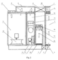
- the painting booth with separated units of ASU (Variants 1 and 2 of the method according to Claim 1, Figs. 1 and 4 ) comprises body 1 with filters 2.
- Filters 2 divide the painting booth into three zones: zone 3 to mix streams of return (recirculated) air and fresh atmosphere air, zone 4 to paint objects (working zone) where the mixed air stream is supplied from zone 3, and zone 5 to extract used air contaminated with EFL vapors and paint's residue particles.
- Body 1 of the painting booth is connected by means of supply ducts 6 and extract ducts 7 with ASU which consists of two main units: unit 8 for return air treatment and intake unit 9.
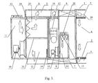
- the painting booth with combined units of ASU (Variants 1 and 2 of the method according to Claim 1, Figs. 2 and 3 ) comprises body 1 with filters 2.
- Filters 2 divide the painting booth into three zones: zone 20 to supply air, zone 4 to paint objects (working zone), and zone 5 to extract used air contaminated with EFL vapors and paint's residue particles.
- Body 1 of the painting booth is connected by means of supply duct 6 and extract duct 7 with ASU which consists of two main units: unit 8 for return air treatment and intake unit 9.
- Unit 8 of ASU (Variant 1 of the method according to Claim 1, Figs. 1 and 2 ) comprises recirculation fan 10 which creates a closed air stream as well as pressure zone 11 designed to divide used air into two streams, the first returning to the painting zone and creating a closed air stream inside the painting booth and ASU, while the second (with EFL vapors) is extracted to atmosphere by means of ARU 12.
- Intake unit 9 comprises intake fan 13 which divides the internal volume of unit 9 into zone 14 responsible for suction and cleaning the fresh air with filters 15 and pressure zone 16, air heater unit 17 being placed either in pressure zone 16 or in suction and cleaning zone 14.
- Intake unit 9 consists of ARU 18, which provides for the required volume of fresh air. ARU 18 and 12 are coordinated to maintain the necessary air pressure inside body 1 of the painting booth.
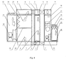
- Unit 8 of ASU (Variant 2 of the method according to Claim 1, Figs. 3 and 4 ) comprises recirculation fan 10 to create a closed air stream and partition 21 which divides the internal volume of unit 8 into three zones: suction zone 22, pressure zone 11 and zone 23 to clean or recirculate return air, and zone 3 to mix air streams, connected with the painting booth by means of supply air duct 6.
- Pressure zone 11 is intended to divide the used air into streams, the first returning to the painting zone which creates a closed air stream inside the painting booth and ASU while the second stream (with EFL vapors) is extracted to atmosphere by means of ARU 12.
- Partition 21 consists of two parts, the lower being air proof, the upper having holes for air which goes from pressure zone 11 to cleaning of return air zone 23 where return air is cleaned by filters 24. Filters 24 may be fitted either at the boundary between zones 11 and 23 into the holes of partition 21 or into supply air duct 6, zones 11 and 23 becoming one zone in this case.
- Zone 23 where return air is cleaned, is connected with air stream mixing zone 3, the latter being connected with intake unit 9 comprising intake fan 13 which divides unit 9 into zone 14, where fresh air is sucked and cleaned by filters 15, and pressure zone 16, with air heater unit 17 being placed either in pressure zone 16 or in suction and cleaning zone 14.
- Intake unit 9 also comprises ARU 18 which supplies the required volume of fresh air.
- ARU 18 and 12 are coordinated to maintain the required air pressure inside body 1 of the painting booth.
- ASU (Variants 1 and 2) can work either in the "Paint” or "Baking” mode.
- By-pass ARU 19 is fitted either in suction zone 22 of unit 8 ( Fig. 3 ) or in suction zone 14 of unit 9 ( Figs. 1 , 2 and 4 ) to operate in the "Baking" mode.
- the painting booth (Variant 3 to realize the method according to Claim 2) comprises body 1 with filters 2.
- Filters 2 divide the painting booth into three zones: zone 20 to supply air, zone 4 to paint objects (working zone), and zone 5 to extract used air contaminated with EFL vapors and paint's residue particles.
- Body 1 of the painting booth is connected by means of supply duct 6 and extract duct 7 with ASU which consists of two main units: unit 8 for return air treatment and intake unit 9.
- Unit 8 of ASU comprises recirculation fan 10 to create a closed air stream and, simultaneously, to suck in fresh air, partition 21 which divides the internal volume of unit 8 into three zones: zone 3 to mix the air streams, pressure zone 11 and zone 23 to clean or recirculate return air.
- Zone 3 is intended to mix streams of used and fresh air
- pressure zone 11 is intended to divide air into two streams, the first returning to the painting zone which creates a closed air stream inside the painting booth and ASU, the second stream with EFL vapors being extracted to atmosphere by ARU 12.
- ARU 25 is fitted into zone 3 to regulate (together with ARU 18 at the intake of unit 9) the proportion of used and fresh air streams supplied by the fan.
- Partition 21 consists of two parts: the lower is air proof, while the upper is made with holes for air coming from pressure zone 11 to return air cleaning zone 23 where the return air is cleaned by filters 24.
- Filters 24 can be placed either at the boundary between zones 11 and 23 in the holes of partition 21 or in supply air duct 6, or combined with filters 2 in the supply air zone, zones 11 and 23 being coupled in this case.
- Zone 3 is connected with intake unit 9 comprising filters 15 and heater unit 17.
- ARU 18 and 12 are coordinated to maintain the required air pressure inside body 1 of the painting booth.
- ASU can be operated either in the "Paint” or "Baking" mode.
- By-pass ARU 19 is provided in fresh air intake unit 9 before heater unit 17 to operate in the "Baking" mode.
- the method of paint booth air feeding to paint with liquid paints can be realized as follows.
- the object to be painted is placed in body 1 of the paint booth (zone 4). Both recirculation 10 and intake 13 fans start working simultaneously when ASU is turned on. Some finely dispersed paint particles and EFL vapors, which are trapped in the air stream, are formed in zone 4 when the object is painted.
- the air stream due to negative pressure created by fan 10, goes through bottom filters 2 of the booth's body, where paint particles are partially arrested, and then part of the air stream containing EFL vapors and finely dispersed dry paint particles is extracted through ARU 12 to be cleaned and/or exhausted to atmosphere, but the main air stream goes to mix with fresh external air supplied by the intake fan into zone 3, which leads to a decreased EFL vapor concentration and further removal of dust and paint in upper filters 2 of the booth's body. After the filters, the uniform mixed air stream is again supplied to the whole area of working zone 4.
- the second stream containing EFL vapors is either cleaned of EFL vapors by sorption or burning, or is directly exhausted to atmosphere.
- the method of paint booth air feeding to paint with liquid paints (variant 2) is realized as follows.
- the object to be painted is placed in body 1 of the paint booth (zone 4).
- Fan 10 creates negative pressure in zone 3, which leads to suction of fresh air from atmosphere. This air is cleaned of dust in filter 15 and then goes through heater unit 17 to stream mixing zone 3.
- the volume of fresh air intake is determined by opening of ARU 18.
- Recirculation fan 10, due to negative pressure in zone 3, also creates negative pressure in zone 5 whereby air is sucked from the working zone inside the painting booth through paint particle cleaning filters 2.
- the used air from zone 5 goes through ARU 25 to zone 3 where it mixes with the fresh air stream.
- the mixed stream is then supplied by fan 10 to zone 11, where it is separated into 2 streams.
- the first stream due to pressure of fan 10, goes through filters 24 which can be fitted into holes in partition 21, proceeds through the air duct to the booth's body, where, as it passes through filters 2, it is again supplied as a uniform stream to the whole area of working zone 4 of the booth.
- the volume of air creating the second stream is determined by ARU 12 opening and is regulated by the operator depending on the amount of excess pressure required in working zone 4 of the painting booth, i.e. a little less than the volume of fresh air supplied.
- the second stream containing EFL vapors is either cleaned of EFL vapors by sorption or burning, or is directly exhausted to atmosphere.
- the Air Supply Unit to supply and extract air from the booth (variant 1) works as follows.
- the object to be painted is placed in body 1 of the paint booth (zone 4).
- Intake fan 13 creates negative pressure in zone 14 and sucks in fresh air which is cleaned of dust by filter 15 and is then supplied through heater 17 to stream mixing zone 3.
- the volume of fresh air sucked in is determined by opening of ARU 18.
- Recirculation fan 10 creates negative pressure in zone 5, whereby air is sucked (extracted) from working zone 4 inside the paint booth by paint particle filters 2. Then, the air is supplied by fan 10 to zone 11, where it is divided into 2 streams.
- the first stream cleaned by additional filters (if available) or not cleaned, goes to zone 3 because of pressure of fan 10, where it is mixed with fresh air also supplied under pressure by fan 13 and, when passing through filters 2, is again supplied as a uniform stream to the whole area of working zone 4 of the booth.
- the volume of air creating the second stream which is exhausted into the cleaning device or atmosphere is determined by ARU 12 opening and is regulated by the operator dependending on how much excess pressure is required in working zone 4 of the painting booth, i.e. a little less than the volume of fresh air supplied.
- the Air Supply Unit to supply and extract air from the booth (variant 2) works as follows.
- the object to be painted is placed in body 1 of the paint booth (zone 4). Both recirculation 10 and intake 13 fans start working simultaneously when ASU is turned on. Some finely dispersed paint particles and EFL vapors, which are trapped in the air stream, are formed in zone 4 when the object is painted.
- the air stream due to negative pressure created by fan 10, goes through bottom filters 2 of the booth's body, where paint particles are partially arrested, and then part of the air stream containing EFL vapors and finely dispersed dry paint particles is extracted through ARU 12 to be cleaned and/or exhausted to atmosphere, while the main air stream goes to fine cleaning filters 24 where additional extraction of finely dispersed paint particles from the return air stream is carried out, and then mixes with fresh external air in zone 3, which leads to a decreased EFL vapor concentration, and finally is further cleaned of dust and paint in upper filters 2. After the filters, the uniform mixed air stream is again supplied to the whole area of working zone 4.
- internal partition 21 allows additional filters of fine cleaning 24 to be placed in return air treatment unit, which significantly improves the degree of air cleaning compared with variant 1 and lengthens the lifetime of upper filters 2 in the painting booth.
- the "Baking" mode (variants 1 and 2) is carried out as follows: the operator opens by-pass ARU 19 and closes ARU 12 and 18 after finishing the painting process. The level of mutual closing of the last two is determined by necessity to maintain some excess pressure in the paint booth body. Fan 13 starts to work in recirculation mode after completing the above steps, sucking air from zone 5 and supplying it through air heater unit 17 to zone 3, which provides fast air heating to the temperature required.
- the Air Supply Unit to supply air to the painting booth (variant 3) works as follows.
- the object to be painted is placed in body 1 of the paint booth (zone 4).
- the main (recirculation) fan 10 starts working when ASU is turned on. Fan 10 creates negative pressure in mixing zone 3 and, through it, in intake unit 9, whereby fresh air is sucked from atmosphere and is cleaned of dust by filter 15. It then goes through heater unit 17 to stream mixing zone 3. The volume of fresh air sucked in is determined by opening of ARU 18.
- Recirculation fan 10 (through zone 3) also creates negative pressure in zone 5 so that air is sucked (extracted) from working zone 4 inside the painting booth through paint particle cleaning filters 2. Used air goes to zone 3 through air duct 7 and ARU 25, where it is mixed with a fresh air stream.
- the stream ratio is regulated by the degree of mutual opening of ARUs 18 and 25. Then, the mixed air stream is supplied by fan 10 to zone 11, where it is separated into 2 streams.
- the first stream due to pressure of fan 10, passes through filters 24 installed in partition 21 and goes to zone 23, then, through air duct 6, to zone 20 of the booth, where, after passing through cleaning filters 2 under pressure of fan 10, it is again supplied as a uniform stream to the whole area of working zone 4 of the booth.
- the volume of air creating the second stream is determined by ARU 12 opening and is regulated by the operator depending on the amount of excess pressure required in working zone 4 of the painting booth, i.e. a little less than the volume of fresh air supplied.
- the "Baking" mode goes as follows: the operator opens by-pass ARU 19 and closes ARUs 12 and 18 after finishing the painting process. The level of mutual closing of the last two is determined by necessity to maintain some excess pressure in the paint booth body. ARU 25 is partly closed to increase the volume of air going through the air heater. Fan 10 starts operating in a full recirculating mode after completing the above steps: it sucks air from zone 5 and supplies it through air heater unit 17 to zone 4 of the booth, which provides fast air heating to the temperature required.
Abstract
Description
- This invention relates to industrial manufacturing and is intended for painting and curing objects, e.g. cars after bodyshop repair, when liquid paints are sprayed on.
- Modern technologies of painting objects with liquid paints need air to be blown through the painting booth body by means of Air Supply Units, hereinafter referred to as ASU, to solve several technical tasks, namely:
- A) to create a laminar air stream in the painting area with a velocity fast enough to evacuate the paint particle aerosole formed when spraying. The modern requirements for air stream velocity are 20-30 cm/sec, which is fast enough for high quality painting of, for example, car's body;
- B) to evacuate vapors of Easy Flammable Liquids, hereinafter referred to as EFL, to a safe level (0,1-0,5 of Low Concentration Limit of Fire Propagation, or Low Explosive Limit, hereinafter referred to as LEL).
- At present, one- or two-air fan ASUs are used [1, 2] comprising either an intake or an extract fan (a group of fans blocked), or both an intake and an extract fan (groups of fans) simultaneously which supply air into the painting zone (the painting booth body) in the "Paint" mode and/or extract it from the painting zone. Moreover, these devices simultaneously solve the above-mentioned tasks in the same air stream, i.e. an air stream sufficient to solve task A is fed from atmosphere through the painting zone during the painting process, task B being solved automatically because of a significantly higher air change than is necessary.
- The above technological solutions are very simple because of a one-way air stream feed into the working area. Yet, this leads to an excessive consumption of fresh air and energy. Besides, many dispersed dry paint particles with a high content of toxic components combined with solvent vapors are emitted into atmosphere, and these emissions are strictly limited by ecological laws in most countries. Elimination of these contaminants from a significant air volume by means of filtration, sorption or burning requires bulky and expensive installations.
- The technological task is therefore to improve the ASU operation in the "Paint" mode in order to decrease the energy costs for air which is supplied to and discharged from the painting zone, as well as it's treatment and subsequent ecological cleaning. The "Baking" mode is similar in all ASUs mentioned and is therefore not considered.
- A car painting system and method are known, which comprise a number of consecutively installed painting booths, so that air is supplied from the first booth to the second, then third etc, until LEL is reached, with subsequent cleaning and/or extraction to atmosphere. The above painting system comprises several ASUs, fans, particle separator units, air valves etc. according to the number of painting booths in the system (see patent
US3807291 ). - This method cannot be applied to a single object painting, a car or its parts after repair, in particular, and is intended for use in a number of automatic (or semiautomatic) painting booths in conveyor manufacturing lines.
- There exists a method to feed air into a conveyor installation and a painting booth for this method which involves separation of the painting booth into a number of consecutive partitions when air into/from each partition is fed by separate fans through separate particle cleaners and the burning of EFL vapor follows the exit from the last partition (see patent
US4587927 ). - Said method can only be used in conveyor automatic painting lines, and the conveyor painting booth is very complicated and not cost-effective, as it requires a great number of fans, particle cleaners, air valves etc. according to the number of partitions inside the painting booth.
- The existing inventions require a significant volume of fresh air, which is equivalent to the standard way of paint booth air feeding (more than 20000 cubic meters per hour, as a rule). Solution of the task, i.e. more economical energy consumption in this group of innovations is based on the principle that when air is routed from one consecutive zone of the painting booth to the next, we use air that has already been heated in the previous zone, the energy consumption being thus lowered, but the air is still routed one-way and not returned to the previous zone, which means that the total amount of air volume has to be cleaned before being discharged to atmosphere after the last paint booth in the sequence, which still requires bulky and expensive systems of EFL vapor utilization.
- Said methods and installations are used in conveyor painting lines, where the manufacturing volume is considerable and the technological process does not involve human labor. They are economically ineffective, however, for painting single objects on a small scale as well as for bodyshop repair, in absence of conveyor and when human presence in the painting booth is necessary. The bodyshop repair, for instance, involves painting of an immobilized car, and only one painting booth is usually available.
- A painting booth for spray coating and a circulation system for the working area, and the method of air supply to paint booth (publication number
WO 98/2808 of 02.07.1998 PCT/CH 97/00468 of 15.12.1997 - Said method uses ASU to supply air from and discharge it back to atmosphere.
- Said spray coating painting booth and circulation system for the working area include ASU to supply to and extract air from the booth. ASU comprises return air treatment and intake units connected together, as well as air ducts, an air regulation unit, hereinafter referred to as ARU, to extract air, ARU to feed air, recirculation and intake fans.
- Said method and installation are not very reliable due to their complexity because the painting booth's working area, to realize the above method, has to be divided into multiple zones, namely: a paintwork zone, extraction zones and used air recirculation zone(s) combined with air stream regulation and/or stop air devices with their control units, fresh air feeding zone with separate stream regulation and/or stop air devices with their control units, up to 12 devices in all, let alone filters, light devices, a complicated installation to mechanically move objects being painted on the working area floor and ASU which is divided into sections to separately supply fresh and return air into the booth and extract it.
- Exploitation of the above-mentioned painting booth and ASU is complicated because it is necessary to control/operate numerous air valves, which distracts the staff from the paint process and increases the time of fresh paint layer exposition to air stream before curing, which increases a possible deposition on the fresh painted surface. Different air supply zones in the booth's body and, consequently, different air flow volumes, also lead to a number of negative effects, in particular:
- 1) Low fire safety because of EFL accumulation in the main ASU volume and paint booth's body in the absence of fresh air feeding to those zones.
- 2) Formation of boundary turbulent air flows between fresh and recirculated air streams because of their different velocities, which leads to paint dispersed particles flying inside the booth and their subsequent potential deposition on the fresh painted surface.
- The technical effect of the group of innovations proposed is improved performance due to a simplified air feeding into the working zone and a simplified ASU design, as well as a higher quality of the painting surface because a uniform (laminar) air flow over the whole area of the painting booth is provided, which allows both the whole of the car (or any other bulky object) and its separate parts to be painted.
- Said technical effect, in part of the method, is achieved (according to variant 1) by the method of paint booth air feeding characterized in that fresh air is fed from and extracted into atmosphere by means of ASU, thereby creating a closed air stream in the painting booth and ASU, whereupon said stream is divided into two after passing the painting zone, the first stream returning to the painting booth either with or without filtering, while the second flow with EFL vapors is extracted to atmosphere, simultaneously an additional fresh air intake is provided from atmosphere, mixed with return air and supplied into the painting zone.
- Besides, the second flow with EFL vapors is either cleaned of EFL vapors by sorption or burning or is directly extracted to atmosphere.
- Said technical effect, in part of the method, is achieved (according to variant 2) by the method of paint booth air feeding characterized in that fresh air is fed from and extracted into atmosphere by means of ASU, thereby creating a closed air stream in the painting booth and ASU, whereupon said stream, after passing the painting zone, is mixed with additional fresh air taken from atmosphere, and is then divided into two streams, the first being fed to the painting booth either with or without filtering, while the second stream with EFL vapors is extracted to atmosphere.
- Besides, the second stream with EFL vapors is either cleaned of EFL vapors by sorption or burning or is directly extracted to atmosphere.
- Said technical result is achieved, in part of the device, due to the fact that ASU for air supply and extraction from the booth (variant 1) comprising a return air treatment unit and an intake unit connected, as well as air ducts, ARU to extract air, ARU to take in fresh air, recirculation and intake fans, has been engineered with return air and fresh air stream mixing zone connected with the painting booth and located either inside the painting booth between the return air treatment unit and intake unit, or above the return air treatment and intake air units.
- Said technical result is achieved, in part of the device, due to the fact that ASU for air supply and extraction from the booth (variant 2) comprising a return air treatment unit and an intake unit connected with each other, as well as air ducts, ARU to extract air, ARU to take in fresh air, recirculation and intake fans, has been engineered with return air and fresh air stream mixing zone connected with the painting booth and located either inside the painting booth between the return air treatment unit and intake unit, or above the return air treatment and intake air units, and a partition to divide the return air treatment unit's internal volume into zones fitted in the return air treatment unit and constructed as two connected parts, the lower part being made air proof and the upper having holes for return air.
- Besides, according to
variant 2, the partition to divide the internal volume of return air treatment unit into zones in ASU for air supply and extraction from the booth creates a suction zone, a pressure zone and either a cleaning or a recirculation zone connected with the air stream mixing zone. - Said technical result is achieved, in part of the device (according to variant 3), due to the fact that ASU for air supply and extraction from the booth containing a return air treatment unit connected with the intake unit, air ducts, ARU to extract air, ARU to take in fresh air as well as a recirculation fan, has been engineered with a return air and fresh air stream mixing zone located inside the return air treatment unit and a partition to divide the return air treatment unit's internal volume into zones which is placed in the return air treatment unit and made up of two connected parts, the lower being air proof and the upper having holes for return air.
- Besides, according to
variant 3, the partition to divide the internal volume of return air treatment unit into zones in ASU for air supply and extraction from the booth creates an air stream suction and mixing zone connected with the intake air unit, a pressure zone, and a zone of either cleaning or recirculation connected with the painting booth. ASU is supplied with a by-pass ARU placed in the intake unit. -
-
Fig. 1 is a painting booth with ASU having two groups of fans and separated units, general view,variant 1. -
Fig. 2 is a painting booth with ASU having two groups of fans and combined units, general view,variant 1. -
Fig. 3 is a painting booth with ASU having two groups of fans and combined units, general view,variant 2. -
Fig. 4 is a painting booth with ASU having two groups of fans and separated units, general view,variant 2. -
Fig. 5 is a painting booth with ASU having one group of fans, general view,variant 3. - The painting booth with separated units of ASU (
Variants Claim 1,Figs. 1 and4 ) comprisesbody 1 withfilters 2.Filters 2 divide the painting booth into three zones:zone 3 to mix streams of return (recirculated) air and fresh atmosphere air,zone 4 to paint objects (working zone) where the mixed air stream is supplied fromzone 3, andzone 5 to extract used air contaminated with EFL vapors and paint's residue particles.Body 1 of the painting booth is connected by means ofsupply ducts 6 andextract ducts 7 with ASU which consists of two main units:unit 8 for return air treatment andintake unit 9. - The painting booth with combined units of ASU (
Variants Claim 1,Figs. 2 and3 ) comprisesbody 1 withfilters 2.Filters 2 divide the painting booth into three zones:zone 20 to supply air,zone 4 to paint objects (working zone), andzone 5 to extract used air contaminated with EFL vapors and paint's residue particles.Body 1 of the painting booth is connected by means ofsupply duct 6 andextract duct 7 with ASU which consists of two main units:unit 8 for return air treatment andintake unit 9. -
Unit 8 of ASU (Variant 1 of the method according toClaim 1,Figs. 1 and2 ) comprisesrecirculation fan 10 which creates a closed air stream as well aspressure zone 11 designed to divide used air into two streams, the first returning to the painting zone and creating a closed air stream inside the painting booth and ASU, while the second (with EFL vapors) is extracted to atmosphere by means of ARU 12. -
Intake unit 9 comprisesintake fan 13 which divides the internal volume ofunit 9 intozone 14 responsible for suction and cleaning the fresh air withfilters 15 andpressure zone 16,air heater unit 17 being placed either inpressure zone 16 or in suction andcleaning zone 14.Intake unit 9 consists of ARU 18, which provides for the required volume of fresh air. ARU 18 and 12 are coordinated to maintain the necessary air pressure insidebody 1 of the painting booth. -
Unit 8 of ASU (Variant 2 of the method according toClaim 1,Figs. 3 and4 ) comprisesrecirculation fan 10 to create a closed air stream andpartition 21 which divides the internal volume ofunit 8 into three zones:suction zone 22,pressure zone 11 andzone 23 to clean or recirculate return air, andzone 3 to mix air streams, connected with the painting booth by means ofsupply air duct 6.Pressure zone 11 is intended to divide the used air into streams, the first returning to the painting zone which creates a closed air stream inside the painting booth and ASU while the second stream (with EFL vapors) is extracted to atmosphere by means of ARU 12. -
Partition 21 consists of two parts, the lower being air proof, the upper having holes for air which goes frompressure zone 11 to cleaning ofreturn air zone 23 where return air is cleaned byfilters 24.Filters 24 may be fitted either at the boundary betweenzones partition 21 or intosupply air duct 6,zones -
Zone 23, where return air is cleaned, is connected with airstream mixing zone 3, the latter being connected withintake unit 9 comprisingintake fan 13 which dividesunit 9 intozone 14, where fresh air is sucked and cleaned byfilters 15, andpressure zone 16, withair heater unit 17 being placed either inpressure zone 16 or in suction and cleaningzone 14. -
Intake unit 9 also comprisesARU 18 which supplies the required volume of fresh air.ARU body 1 of the painting booth. - ASU (
Variants 1 and 2) can work either in the "Paint" or "Baking" mode. By-pass ARU 19 is fitted either insuction zone 22 of unit 8 (Fig. 3 ) or insuction zone 14 of unit 9 (Figs. 1 ,2 and4 ) to operate in the "Baking" mode. - The painting booth (
Variant 3 to realize the method according to Claim 2) comprisesbody 1 withfilters 2.Filters 2 divide the painting booth into three zones:zone 20 to supply air,zone 4 to paint objects (working zone), andzone 5 to extract used air contaminated with EFL vapors and paint's residue particles.Body 1 of the painting booth is connected by means ofsupply duct 6 and extractduct 7 with ASU which consists of two main units:unit 8 for return air treatment andintake unit 9. -
Unit 8 of ASU comprisesrecirculation fan 10 to create a closed air stream and, simultaneously, to suck in fresh air,partition 21 which divides the internal volume ofunit 8 into three zones:zone 3 to mix the air streams,pressure zone 11 andzone 23 to clean or recirculate return air.Zone 3 is intended to mix streams of used and fresh air, whilepressure zone 11 is intended to divide air into two streams, the first returning to the painting zone which creates a closed air stream inside the painting booth and ASU, the second stream with EFL vapors being extracted to atmosphere byARU 12. -
ARU 25 is fitted intozone 3 to regulate (together withARU 18 at the intake of unit 9) the proportion of used and fresh air streams supplied by the fan.Partition 21 consists of two parts: the lower is air proof, while the upper is made with holes for air coming frompressure zone 11 to returnair cleaning zone 23 where the return air is cleaned byfilters 24.Filters 24 can be placed either at the boundary betweenzones partition 21 or insupply air duct 6, or combined withfilters 2 in the supply air zone,zones -
Zone 3 is connected withintake unit 9 comprisingfilters 15 andheater unit 17. -
ARU body 1 of the painting booth. - ASU can be operated either in the "Paint" or "Baking" mode. By-
pass ARU 19 is provided in freshair intake unit 9 beforeheater unit 17 to operate in the "Baking" mode. - The method of paint booth air feeding to paint with liquid paints (variant 1) can be realized as follows.
- To work in the "Paint" mode, the object to be painted is placed in
body 1 of the paint booth (zone 4). Bothrecirculation 10 andintake 13 fans start working simultaneously when ASU is turned on. Some finely dispersed paint particles and EFL vapors, which are trapped in the air stream, are formed inzone 4 when the object is painted. The air stream, due to negative pressure created byfan 10, goes throughbottom filters 2 of the booth's body, where paint particles are partially arrested, and then part of the air stream containing EFL vapors and finely dispersed dry paint particles is extracted throughARU 12 to be cleaned and/or exhausted to atmosphere, but the main air stream goes to mix with fresh external air supplied by the intake fan intozone 3, which leads to a decreased EFL vapor concentration and further removal of dust and paint inupper filters 2 of the booth's body. After the filters, the uniform mixed air stream is again supplied to the whole area of workingzone 4. - The second stream containing EFL vapors is either cleaned of EFL vapors by sorption or burning, or is directly exhausted to atmosphere.
- The method of paint booth air feeding to paint with liquid paints (variant 2) is realized as follows.
- To work in the "Paint" mode, the object to be painted is placed in
body 1 of the paint booth (zone 4).Fan 10 creates negative pressure inzone 3, which leads to suction of fresh air from atmosphere. This air is cleaned of dust infilter 15 and then goes throughheater unit 17 to stream mixingzone 3. The volume of fresh air intake is determined by opening ofARU 18.Recirculation fan 10, due to negative pressure inzone 3, also creates negative pressure inzone 5 whereby air is sucked from the working zone inside the painting booth through paint particle cleaning filters 2. The used air fromzone 5 goes throughARU 25 tozone 3 where it mixes with the fresh air stream. The mixed stream is then supplied byfan 10 tozone 11, where it is separated into 2 streams. The first stream, due to pressure offan 10, goes throughfilters 24 which can be fitted into holes inpartition 21, proceeds through the air duct to the booth's body, where, as it passes throughfilters 2, it is again supplied as a uniform stream to the whole area of workingzone 4 of the booth. The volume of air creating the second stream is determined byARU 12 opening and is regulated by the operator depending on the amount of excess pressure required in workingzone 4 of the painting booth, i.e. a little less than the volume of fresh air supplied. - The second stream containing EFL vapors is either cleaned of EFL vapors by sorption or burning, or is directly exhausted to atmosphere.
- The Air Supply Unit to supply and extract air from the booth (variant 1) works as follows.
- To work in the "Paint" mode, the object to be painted is placed in
body 1 of the paint booth (zone 4).Intake fan 13 creates negative pressure inzone 14 and sucks in fresh air which is cleaned of dust byfilter 15 and is then supplied throughheater 17 to stream mixingzone 3. The volume of fresh air sucked in is determined by opening ofARU 18.Recirculation fan 10 creates negative pressure inzone 5, whereby air is sucked (extracted) from workingzone 4 inside the paint booth by paint particle filters 2. Then, the air is supplied byfan 10 tozone 11, where it is divided into 2 streams. The first stream, cleaned by additional filters (if available) or not cleaned, goes tozone 3 because of pressure offan 10, where it is mixed with fresh air also supplied under pressure byfan 13 and, when passing throughfilters 2, is again supplied as a uniform stream to the whole area of workingzone 4 of the booth. The volume of air creating the second stream which is exhausted into the cleaning device or atmosphere is determined byARU 12 opening and is regulated by the operator dependending on how much excess pressure is required in workingzone 4 of the painting booth, i.e. a little less than the volume of fresh air supplied. - The Air Supply Unit to supply and extract air from the booth (variant 2) works as follows.
- To work in the "Paint" mode, the object to be painted is placed in
body 1 of the paint booth (zone 4). Bothrecirculation 10 andintake 13 fans start working simultaneously when ASU is turned on. Some finely dispersed paint particles and EFL vapors, which are trapped in the air stream, are formed inzone 4 when the object is painted. The air stream, due to negative pressure created byfan 10, goes throughbottom filters 2 of the booth's body, where paint particles are partially arrested, and then part of the air stream containing EFL vapors and finely dispersed dry paint particles is extracted throughARU 12 to be cleaned and/or exhausted to atmosphere, while the main air stream goes to fine cleaning filters 24 where additional extraction of finely dispersed paint particles from the return air stream is carried out, and then mixes with fresh external air inzone 3, which leads to a decreased EFL vapor concentration, and finally is further cleaned of dust and paint inupper filters 2. After the filters, the uniform mixed air stream is again supplied to the whole area of workingzone 4. - In said variant,
internal partition 21 allows additional filters of fine cleaning 24 to be placed in return air treatment unit, which significantly improves the degree of air cleaning compared withvariant 1 and lengthens the lifetime ofupper filters 2 in the painting booth. - The "Baking" mode (
variants 1 and 2) is carried out as follows: the operator opens by-pass ARU 19 and closesARU Fan 13 starts to work in recirculation mode after completing the above steps, sucking air fromzone 5 and supplying it throughair heater unit 17 tozone 3, which provides fast air heating to the temperature required. - The Air Supply Unit to supply air to the painting booth (variant 3) works as follows.
- To work in the "Paint" mode, the object to be painted is placed in
body 1 of the paint booth (zone 4). The main (recirculation)fan 10 starts working when ASU is turned on.Fan 10 creates negative pressure in mixingzone 3 and, through it, inintake unit 9, whereby fresh air is sucked from atmosphere and is cleaned of dust byfilter 15. It then goes throughheater unit 17 to stream mixingzone 3. The volume of fresh air sucked in is determined by opening ofARU 18. Recirculation fan 10 (through zone 3) also creates negative pressure inzone 5 so that air is sucked (extracted) from workingzone 4 inside the painting booth through paint particle cleaning filters 2. Used air goes tozone 3 throughair duct 7 andARU 25, where it is mixed with a fresh air stream. The stream ratio is regulated by the degree of mutual opening ofARUs fan 10 tozone 11, where it is separated into 2 streams. The first stream, due to pressure offan 10, passes throughfilters 24 installed inpartition 21 and goes tozone 23, then, throughair duct 6, to zone 20 of the booth, where, after passing throughcleaning filters 2 under pressure offan 10, it is again supplied as a uniform stream to the whole area of workingzone 4 of the booth. The volume of air creating the second stream is determined byARU 12 opening and is regulated by the operator depending on the amount of excess pressure required in workingzone 4 of the painting booth, i.e. a little less than the volume of fresh air supplied. - The "Baking" mode goes as follows: the operator opens by-
pass ARU 19 and closes ARUs 12 and 18 after finishing the painting process. The level of mutual closing of the last two is determined by necessity to maintain some excess pressure in the paint booth body.ARU 25 is partly closed to increase the volume of air going through the air heater.Fan 10 starts operating in a full recirculating mode after completing the above steps: it sucks air fromzone 5 and supplies it throughair heater unit 17 tozone 4 of the booth, which provides fast air heating to the temperature required. - Application of the group of innovations proposed leads to:
- a) lower investment costs because of a simplified engineering design of the air units;
- b) improvement of exploitation properties because of a lower energy consumption when moving and heating the air;
- c) improved ecological properties because less atmospheric air is consumed and its subsequent complete cleaning before exhaust to atmosphere is facilitated.
-
Claims (9)
- The method of paint booth air feeding to paint with liquid paints, characterized in that the air is fed from atmosphere and exhausted to atmosphere by means of an air supply unit, differs in that a closed air stream is created inside the painting booth and air supply unit, wherein said stream, after passing through the painting zone is divided into two streams, the first returning to the painting booth either with or without filter cleaning, while the second stream, containing vapors of flammable liquids, is extracted to atmosphere, simultaneously, additional air is taken from atmosphere, mixed with said return air and supplied to the painting zone of the paint booth.
- The method of paint booth air feeding to paint with liquid paints, characterized in that the air is fed from atmosphere and extracted to atmosphere by means of an air supply unit, differs in that a closed air stream is created inside the painting booth and air supply unit, wherein said stream, after passing through the painting zone, is mixed with additional air taken from atmosphere and then divided into two streams, the first returning to the painting booth either with or without filter cleaning, the second stream, containing vapors of flammable liquids, being extracted to atmosphere.
- The method, according to claims 1 and 2, characterized in that the second air stream with vapors of flammable liquid is either cleaned of said vapors by sorption or burning, or directly exhausted to atmosphere.
- The Air Supply Unit to feed and extract air from the painting booth which contains a return air treatment unit and an intake unit connected, air ducts, an air regulation unit to extract air, an air regulation unit to take in fresh air, recirculation and intake fans, characterized in that it has a zone to mix the return air stream and fresh air which is connected with the paint booth and is located either in the painting booth between the return air treatment unit and intake unit, or above the return air treatment unit and intake unit.
- The Air Supply Unit to feed and extract air from the painting booth which contains a return air treatment unit and an intake unit connected, air ducts, an air regulation unit to extract air, an air regulation unit to take in fresh air, recirculation and intake fans, characterized in that it has a zone to mix the return air stream and fresh air which is connected with the paint booth and is located either in the painting booth between the return air treatment unit and the intake unit, or above the return air treatment unit and the intake unit, as well as a partition to divide the internal volume of the return air treatment unit into zones located in the return air treatment unit and configured as two connected parts, the lower being made air proof, the upper having holes for return air.
- The Air Supply Unit, according to Claim 5, characterized in that a partition to divide the internal volume of the return air treatment unit into zones creates a suction zone, a pressure zone and a zone of either cleaning or recirculation, connected with the air stream mixing zone.
- The Air Supply Unit to feed and extract air from the painting booth which contains a return air treatment unit and an intake unit connected, air ducts, an air regulation unit to extract air, an air regulation unit to take in fresh air, a recirculation fan, characterized in that it has a zone to mix the return air stream and fresh air located inside the internal volume of the return air treatment unit and a partition to divide the internal volume of the return air treatment unit into zones located in the return air treatment unit and configured as two connected parts, the lower being air proof, and the upper having holes for return air.
- The Air Supply Unit, according to Claim 7, characterized in that a partition to divide the internal volume of the return air treatment unit into zones creates a suction and air stream mixing zone connected with the intake unit, a pressure zone, and a zone of either cleaning or recirculation connected with the paint booth.
- The Air Supply Unit, according to Claim 7, characterized in that it has a by-pass air regulation unit fitted in the air stream mixing zone.
Priority Applications (1)
| Application Number | Priority Date | Filing Date | Title |
|---|---|---|---|
| PL09838958T PL2390607T3 (en) | 2009-01-23 | 2009-12-28 | Method for supplying air into a spray booth (embodiments) and a ventilation unit for implementing the method (embodiments) |
Applications Claiming Priority (2)
| Application Number | Priority Date | Filing Date | Title |
|---|---|---|---|
| RU2009102024/06A RU2402718C2 (en) | 2009-01-23 | 2009-01-23 | Method of feeding air into spray cabinet for spray painting by liquid paints (versions) and ventilation unit to this end (versions) |
| PCT/RU2009/000737 WO2010085176A2 (en) | 2009-01-23 | 2009-12-28 | Method for supplying air into a spray booth (embodiments) and a ventilation unit for implementing the method (embodiments) |
Publications (3)
| Publication Number | Publication Date |
|---|---|
| EP2390607A2 true EP2390607A2 (en) | 2011-11-30 |
| EP2390607B1 EP2390607B1 (en) | 2018-03-07 |
| EP2390607B9 EP2390607B9 (en) | 2018-10-10 |
Family
ID=42356360
Family Applications (1)
| Application Number | Title | Priority Date | Filing Date |
|---|---|---|---|
| EP09838958.8A Not-in-force EP2390607B9 (en) | 2009-01-23 | 2009-12-28 | Method for supplying air into a spray booth (embodiments) and a ventilation unit for implementing the method (embodiments) |
Country Status (8)
| Country | Link |
|---|---|
| US (2) | US9764347B2 (en) |
| EP (1) | EP2390607B9 (en) |
| CA (1) | CA2750600C (en) |
| ES (1) | ES2672104T3 (en) |
| PL (1) | PL2390607T3 (en) |
| RU (1) | RU2402718C2 (en) |
| TR (1) | TR201807697T4 (en) |
| WO (1) | WO2010085176A2 (en) |
Cited By (3)
| Publication number | Priority date | Publication date | Assignee | Title |
|---|---|---|---|---|
| CN106574792A (en) * | 2014-08-29 | 2017-04-19 | 豪威株式会社 | Ventilation cleaner and method for controlling same |
| CN107309126A (en) * | 2017-07-12 | 2017-11-03 | 芜湖宝骐汽车制造有限公司 | A kind of logistic car application, drying production line and its operating method |
| CN110721863A (en) * | 2019-10-14 | 2020-01-24 | 昆山德瑞泰自动设备有限公司 | Dry-type spray room |
Families Citing this family (9)
| Publication number | Priority date | Publication date | Assignee | Title |
|---|---|---|---|---|
| DE102010054212A1 (en) * | 2010-12-11 | 2012-06-14 | Eisenmann Ag | Plant for painting objects |
| KR102056693B1 (en) * | 2011-07-27 | 2019-12-17 | 듀르 시스템스 아게 | Painting facility and method for operation a painting facility |
| DE102012001563B4 (en) * | 2012-01-27 | 2019-05-09 | Dürr Systems Ag | Paint booth with a coating agent line and corresponding production method for the coating agent line |
| DE102012003299A1 (en) * | 2012-02-18 | 2013-08-22 | Eisenmann Ag | Method of treating objects and installation therefor |
| US11364515B2 (en) | 2012-07-25 | 2022-06-21 | David John Utting | Transportable vehicle enclosures |
| RU2614673C1 (en) * | 2016-02-24 | 2017-03-28 | Закрытое акционерное общество "Научно-производственное объединение "ЭЛКОМ" | Method of air supply into chamber for painting liquid paints and chambers for carrying out method (versions) |
| US11076501B2 (en) * | 2017-05-23 | 2021-07-27 | Crestron Electronics, Inc. | Apparatus for cooling electronic circuitry |
| US11711904B2 (en) * | 2016-06-03 | 2023-07-25 | Crestron Electronics, Inc. | Apparatus for cooling electronic circuitry |
| CN110653111B (en) * | 2019-10-14 | 2020-11-20 | 昆山德瑞泰自动设备有限公司 | Automatic spraying room with waste gas recovery system |
Family Cites Families (20)
| Publication number | Priority date | Publication date | Assignee | Title |
|---|---|---|---|---|
| US3395972A (en) * | 1965-05-20 | 1968-08-06 | Universal Oil Prod Co | Method of cleaning and purifying particle laden discharge streams |
| US3807291A (en) | 1972-03-27 | 1974-04-30 | Du Pont | Improved painting system |
| CH611811A5 (en) * | 1976-03-10 | 1979-06-29 | Waelti Gebrueder Ag | Method for ventilating paint spraying systems and paint spraying system for carrying out the method |
| SE454328B (en) * | 1982-04-30 | 1988-04-25 | Flaekt Ab | PROCEDURE AND DEVICE FOR VENTILATION OF A SPRAYBOX |
| DE3334257C1 (en) | 1983-09-22 | 1985-02-14 | RMG Beierling GmbH, 4791 Altenbeken | Painting and evaporation system with forced air ventilation |
| DE3408087A1 (en) | 1984-03-05 | 1985-09-05 | Viktor Durst Apparate und Behälter, 7129 Pfaffenhofen | Spraying cabin for spraying and drying objects |
| JPS60190256A (en) * | 1984-03-09 | 1985-09-27 | Toyota Motor Corp | Removal of paint mist in exhaust recirculation type painting booth |
| US5113600A (en) * | 1989-09-14 | 1992-05-19 | Binks Manufacturing Company | Combination paint spray booth-drying oven with single air fan |
| US5395285A (en) | 1990-12-03 | 1995-03-07 | Monarch Industries (Aust) Pty. Ltd. | Dehumidifier |
| BE1008634A6 (en) * | 1994-09-08 | 1996-07-02 | Sima Societe Anonyme | Process and installation for spray gun painting anA method and installation for spray painting and drying d drying |
| BE1009345A3 (en) * | 1995-04-19 | 1997-02-04 | Belmeko Engineering Nv | Treatment method and device with forced air circulation |
| US6263485B1 (en) | 1996-07-11 | 2001-07-17 | Andrew Schofield | Method and apparatus for describing an interface definition language-defined interface, operation, and data type |
| EP0849001A1 (en) * | 1996-12-20 | 1998-06-24 | Robert sen. Wälti | Spray booth and air circulation system for a workspace |
| DE19850905B4 (en) | 1998-11-05 | 2007-10-18 | Gerhard Kurz | Device for power control |
| FR2848291B1 (en) * | 2002-12-06 | 2005-02-04 | Delta Prot | VENTILATION BLOCK FOR GARMENT AS A SCAPHANDRE OR THE LIKE |
| DE20309327U1 (en) * | 2003-06-17 | 2003-09-18 | Wolf Stahlbau Kg | Device for painting and drying vehicles and vehicle parts |
| US7014338B2 (en) * | 2003-09-26 | 2006-03-21 | Global Finishing Solutions Canada, Inc. | Spray booth |
| KR100543723B1 (en) * | 2005-06-27 | 2006-01-20 | 주식회사 오토기기 | Painting booth for hot-air drying |
| TWM299274U (en) * | 2006-05-04 | 2006-10-11 | Ind Tech Res Inst | Automatically cleaned storage and retrieve system |
| JP2009285572A (en) * | 2008-05-29 | 2009-12-10 | Auto Co Ltd | Fuel-saving type coating booth with improved hot air circulation manner |
-
2009
- 2009-01-23 RU RU2009102024/06A patent/RU2402718C2/en not_active IP Right Cessation
- 2009-12-28 ES ES09838958.8T patent/ES2672104T3/en active Active
- 2009-12-28 US US13/145,593 patent/US9764347B2/en not_active Expired - Fee Related
- 2009-12-28 CA CA2750600A patent/CA2750600C/en not_active Expired - Fee Related
- 2009-12-28 PL PL09838958T patent/PL2390607T3/en unknown
- 2009-12-28 EP EP09838958.8A patent/EP2390607B9/en not_active Not-in-force
- 2009-12-28 WO PCT/RU2009/000737 patent/WO2010085176A2/en active Application Filing
-
2010
- 2010-12-28 TR TR2018/07697T patent/TR201807697T4/en unknown
-
2017
- 2017-08-11 US US15/674,951 patent/US10471456B2/en not_active Expired - Fee Related
Non-Patent Citations (1)
| Title |
|---|
| See references of WO2010085176A2 * |
Cited By (4)
| Publication number | Priority date | Publication date | Assignee | Title |
|---|---|---|---|---|
| CN106574792A (en) * | 2014-08-29 | 2017-04-19 | 豪威株式会社 | Ventilation cleaner and method for controlling same |
| CN107309126A (en) * | 2017-07-12 | 2017-11-03 | 芜湖宝骐汽车制造有限公司 | A kind of logistic car application, drying production line and its operating method |
| CN107309126B (en) * | 2017-07-12 | 2020-03-10 | 芜湖宝骐汽车制造有限公司 | Logistics vehicle coating and drying production line and operation method thereof |
| CN110721863A (en) * | 2019-10-14 | 2020-01-24 | 昆山德瑞泰自动设备有限公司 | Dry-type spray room |
Also Published As
| Publication number | Publication date |
|---|---|
| RU2402718C2 (en) | 2010-10-27 |
| RU2009102024A (en) | 2010-07-27 |
| PL2390607T3 (en) | 2018-10-31 |
| TR201807697T4 (en) | 2018-06-21 |
| WO2010085176A3 (en) | 2011-05-12 |
| WO2010085176A2 (en) | 2010-07-29 |
| WO2010085176A4 (en) | 2011-06-30 |
| ES2672104T3 (en) | 2018-06-12 |
| EP2390607B1 (en) | 2018-03-07 |
| CA2750600A1 (en) | 2010-07-29 |
| CA2750600C (en) | 2018-09-18 |
| US9764347B2 (en) | 2017-09-19 |
| US20170341100A1 (en) | 2017-11-30 |
| US20110275300A1 (en) | 2011-11-10 |
| EP2390607B9 (en) | 2018-10-10 |
| US10471456B2 (en) | 2019-11-12 |
Similar Documents
| Publication | Publication Date | Title |
|---|---|---|
| US10471456B2 (en) | Method of paint booth air feeding (variants) and air supply unit to realize the method (variants) | |
| US8535420B2 (en) | Filter device for separating paint overspray | |
| CN101992426B (en) | Blast room | |
| JP2008536661A5 (en) | ||
| EP2556874A1 (en) | Filtering apparatus, spray painting booth with the filtering apparatus, and simplified spray painting booth with the filtering apparatus | |
| JP5422814B2 (en) | Paint collection system | |
| ATE30125T1 (en) | POWDER SPRAY CABIN. | |
| CN105709968A (en) | Layered shelf type paint mist separating device and method for separating over-spray objects | |
| US10857494B2 (en) | Exhaust configuration for a wet scrubber | |
| CN105032668A (en) | Side draught type water-free spraying system | |
| MX2012006390A (en) | Apparatus and method for recovery and dry treatment of overs pray in a painting booth. | |
| WO2017152598A1 (en) | Paint spray booth system having high paint capture rate | |
| CN104084344A (en) | Paint spraying chamber paint mist capture technology | |
| CN106140545B (en) | Double air inlet water rotation type water-screen cabinets | |
| WO2017152431A1 (en) | Paint spray booth system having high paint capture rate | |
| CN206104221U (en) | Two air inlet water rotating formula cascade cabinets | |
| US20060243202A1 (en) | Aircraft spray booth | |
| CN205816047U (en) | A kind of dry spray booth | |
| CN207204441U (en) | A kind of coating cloud acquisition equipment | |
| CN208458191U (en) | A kind of ventilating system of laboratory operation platform | |
| CN206853972U (en) | A kind of paint spray booth | |
| CN105499040A (en) | Multistage paint mist trapping device and method for trapping and separating overspray matters | |
| CN107029501A (en) | One kind calcining exhaust gas processing device | |
| CN206138883U (en) | Mist purification system equipment sprays paint | |
| CN106622830A (en) | Paint spraying system with water cyclone device |
Legal Events
| Date | Code | Title | Description |
|---|---|---|---|
| PUAI | Public reference made under article 153(3) epc to a published international application that has entered the european phase |
Free format text: ORIGINAL CODE: 0009012 |
|
| 17P | Request for examination filed |
Effective date: 20110809 |
|
| AK | Designated contracting states |
Kind code of ref document: A2 Designated state(s): AT BE BG CH CY CZ DE DK EE ES FI FR GB GR HR HU IE IS IT LI LT LU LV MC MK MT NL NO PL PT RO SE SI SK SM TR |
|
| DAX | Request for extension of the european patent (deleted) | ||
| 17Q | First examination report despatched |
Effective date: 20121217 |
|
| GRAP | Despatch of communication of intention to grant a patent |
Free format text: ORIGINAL CODE: EPIDOSNIGR1 |
|
| INTG | Intention to grant announced |
Effective date: 20170929 |
|
| GRAS | Grant fee paid |
Free format text: ORIGINAL CODE: EPIDOSNIGR3 |
|
| GRAA | (expected) grant |
Free format text: ORIGINAL CODE: 0009210 |
|
| AK | Designated contracting states |
Kind code of ref document: B1 Designated state(s): AT BE BG CH CY CZ DE DK EE ES FI FR GB GR HR HU IE IS IT LI LT LU LV MC MK MT NL NO PL PT RO SE SI SK SM TR |
|
| REG | Reference to a national code |
Ref country code: GB Ref legal event code: FG4D |
|
| REG | Reference to a national code |
Ref country code: AT Ref legal event code: REF Ref document number: 977015 Country of ref document: AT Kind code of ref document: T Effective date: 20180315 Ref country code: CH Ref legal event code: EP |
|
| REG | Reference to a national code |
Ref country code: IE Ref legal event code: FG4D |
|
| REG | Reference to a national code |
Ref country code: DE Ref legal event code: R096 Ref document number: 602009051174 Country of ref document: DE |
|
| GRAT | Correction requested after decision to grant or after decision to maintain patent in amended form |
Free format text: ORIGINAL CODE: EPIDOSNCDEC |
|
| REG | Reference to a national code |
Ref country code: ES Ref legal event code: FG2A Ref document number: 2672104 Country of ref document: ES Kind code of ref document: T3 Effective date: 20180612 |
|
| REG | Reference to a national code |
Ref country code: NL Ref legal event code: MP Effective date: 20180307 |
|
| REG | Reference to a national code |
Ref country code: LT Ref legal event code: MG4D |
|
| PG25 | Lapsed in a contracting state [announced via postgrant information from national office to epo] |
Ref country code: NO Free format text: LAPSE BECAUSE OF FAILURE TO SUBMIT A TRANSLATION OF THE DESCRIPTION OR TO PAY THE FEE WITHIN THE PRESCRIBED TIME-LIMIT Effective date: 20180607 Ref country code: HR Free format text: LAPSE BECAUSE OF FAILURE TO SUBMIT A TRANSLATION OF THE DESCRIPTION OR TO PAY THE FEE WITHIN THE PRESCRIBED TIME-LIMIT Effective date: 20180307 Ref country code: LT Free format text: LAPSE BECAUSE OF FAILURE TO SUBMIT A TRANSLATION OF THE DESCRIPTION OR TO PAY THE FEE WITHIN THE PRESCRIBED TIME-LIMIT Effective date: 20180307 Ref country code: CY Free format text: LAPSE BECAUSE OF FAILURE TO SUBMIT A TRANSLATION OF THE DESCRIPTION OR TO PAY THE FEE WITHIN THE PRESCRIBED TIME-LIMIT Effective date: 20180307 Ref country code: FI Free format text: LAPSE BECAUSE OF FAILURE TO SUBMIT A TRANSLATION OF THE DESCRIPTION OR TO PAY THE FEE WITHIN THE PRESCRIBED TIME-LIMIT Effective date: 20180307 |
|
| REG | Reference to a national code |
Ref country code: AT Ref legal event code: MK05 Ref document number: 977015 Country of ref document: AT Kind code of ref document: T Effective date: 20180307 |
|
| PG25 | Lapsed in a contracting state [announced via postgrant information from national office to epo] |
Ref country code: SE Free format text: LAPSE BECAUSE OF FAILURE TO SUBMIT A TRANSLATION OF THE DESCRIPTION OR TO PAY THE FEE WITHIN THE PRESCRIBED TIME-LIMIT Effective date: 20180307 Ref country code: LV Free format text: LAPSE BECAUSE OF FAILURE TO SUBMIT A TRANSLATION OF THE DESCRIPTION OR TO PAY THE FEE WITHIN THE PRESCRIBED TIME-LIMIT Effective date: 20180307 Ref country code: BG Free format text: LAPSE BECAUSE OF FAILURE TO SUBMIT A TRANSLATION OF THE DESCRIPTION OR TO PAY THE FEE WITHIN THE PRESCRIBED TIME-LIMIT Effective date: 20180607 Ref country code: GR Free format text: LAPSE BECAUSE OF FAILURE TO SUBMIT A TRANSLATION OF THE DESCRIPTION OR TO PAY THE FEE WITHIN THE PRESCRIBED TIME-LIMIT Effective date: 20180608 |
|
| REG | Reference to a national code |
Ref country code: CH Ref legal event code: PK Free format text: BERICHTIGUNG B9 |
|
| PG25 | Lapsed in a contracting state [announced via postgrant information from national office to epo] |
Ref country code: EE Free format text: LAPSE BECAUSE OF FAILURE TO SUBMIT A TRANSLATION OF THE DESCRIPTION OR TO PAY THE FEE WITHIN THE PRESCRIBED TIME-LIMIT Effective date: 20180307 Ref country code: RO Free format text: LAPSE BECAUSE OF FAILURE TO SUBMIT A TRANSLATION OF THE DESCRIPTION OR TO PAY THE FEE WITHIN THE PRESCRIBED TIME-LIMIT Effective date: 20180307 Ref country code: NL Free format text: LAPSE BECAUSE OF FAILURE TO SUBMIT A TRANSLATION OF THE DESCRIPTION OR TO PAY THE FEE WITHIN THE PRESCRIBED TIME-LIMIT Effective date: 20180307 |
|
| PG25 | Lapsed in a contracting state [announced via postgrant information from national office to epo] |
Ref country code: SK Free format text: LAPSE BECAUSE OF FAILURE TO SUBMIT A TRANSLATION OF THE DESCRIPTION OR TO PAY THE FEE WITHIN THE PRESCRIBED TIME-LIMIT Effective date: 20180307 Ref country code: SM Free format text: LAPSE BECAUSE OF FAILURE TO SUBMIT A TRANSLATION OF THE DESCRIPTION OR TO PAY THE FEE WITHIN THE PRESCRIBED TIME-LIMIT Effective date: 20180307 Ref country code: AT Free format text: LAPSE BECAUSE OF FAILURE TO SUBMIT A TRANSLATION OF THE DESCRIPTION OR TO PAY THE FEE WITHIN THE PRESCRIBED TIME-LIMIT Effective date: 20180307 |
|
| REG | Reference to a national code |
Ref country code: DE Ref legal event code: R097 Ref document number: 602009051174 Country of ref document: DE |
|
| PG25 | Lapsed in a contracting state [announced via postgrant information from national office to epo] |
Ref country code: PT Free format text: LAPSE BECAUSE OF FAILURE TO SUBMIT A TRANSLATION OF THE DESCRIPTION OR TO PAY THE FEE WITHIN THE PRESCRIBED TIME-LIMIT Effective date: 20180709 |
|
| RIC2 | Information provided on ipc code assigned after grant |
Ipc: B05B 15/12 20181130ALI20110512BHEP Ipc: F26B 21/04 20060101AFI20110512BHEP |
|
| PLBE | No opposition filed within time limit |
Free format text: ORIGINAL CODE: 0009261 |
|
| STAA | Information on the status of an ep patent application or granted ep patent |
Free format text: STATUS: NO OPPOSITION FILED WITHIN TIME LIMIT |
|
| REG | Reference to a national code |
Ref country code: CH Ref legal event code: PK Free format text: BERICHTIGUNGEN |
|
| PG25 | Lapsed in a contracting state [announced via postgrant information from national office to epo] |
Ref country code: DK Free format text: LAPSE BECAUSE OF FAILURE TO SUBMIT A TRANSLATION OF THE DESCRIPTION OR TO PAY THE FEE WITHIN THE PRESCRIBED TIME-LIMIT Effective date: 20180307 |
|
| REG | Reference to a national code |
Ref country code: CH Ref legal event code: PK Free format text: BERICHTIGUNGEN |
|
| 26N | No opposition filed |
Effective date: 20181210 |
|
| RIC2 | Information provided on ipc code assigned after grant |
Ipc: B05B 15/12 20060101ALI20110512BHEP Ipc: F26B 21/04 20060101AFI20110512BHEP |
|
| PG25 | Lapsed in a contracting state [announced via postgrant information from national office to epo] |
Ref country code: SI Free format text: LAPSE BECAUSE OF FAILURE TO SUBMIT A TRANSLATION OF THE DESCRIPTION OR TO PAY THE FEE WITHIN THE PRESCRIBED TIME-LIMIT Effective date: 20180307 |
|
| REG | Reference to a national code |
Ref country code: CH Ref legal event code: PL |
|
| PG25 | Lapsed in a contracting state [announced via postgrant information from national office to epo] |
Ref country code: MC Free format text: LAPSE BECAUSE OF FAILURE TO SUBMIT A TRANSLATION OF THE DESCRIPTION OR TO PAY THE FEE WITHIN THE PRESCRIBED TIME-LIMIT Effective date: 20180307 Ref country code: LU Free format text: LAPSE BECAUSE OF NON-PAYMENT OF DUE FEES Effective date: 20181228 |
|
| REG | Reference to a national code |
Ref country code: IE Ref legal event code: MM4A |
|
| PG25 | Lapsed in a contracting state [announced via postgrant information from national office to epo] |
Ref country code: IE Free format text: LAPSE BECAUSE OF NON-PAYMENT OF DUE FEES Effective date: 20181228 |
|
| PGFP | Annual fee paid to national office [announced via postgrant information from national office to epo] |
Ref country code: PL Payment date: 20190930 Year of fee payment: 11 |
|
| PG25 | Lapsed in a contracting state [announced via postgrant information from national office to epo] |
Ref country code: LI Free format text: LAPSE BECAUSE OF NON-PAYMENT OF DUE FEES Effective date: 20181231 Ref country code: CH Free format text: LAPSE BECAUSE OF NON-PAYMENT OF DUE FEES Effective date: 20181231 |
|
| PG25 | Lapsed in a contracting state [announced via postgrant information from national office to epo] |
Ref country code: MT Free format text: LAPSE BECAUSE OF NON-PAYMENT OF DUE FEES Effective date: 20181228 |
|
| PGFP | Annual fee paid to national office [announced via postgrant information from national office to epo] |
Ref country code: DE Payment date: 20191031 Year of fee payment: 11 |
|
| PGFP | Annual fee paid to national office [announced via postgrant information from national office to epo] |
Ref country code: BE Payment date: 20191031 Year of fee payment: 11 Ref country code: FR Payment date: 20191030 Year of fee payment: 11 Ref country code: IT Payment date: 20191114 Year of fee payment: 11 |
|
| PGFP | Annual fee paid to national office [announced via postgrant information from national office to epo] |
Ref country code: GB Payment date: 20191013 Year of fee payment: 11 Ref country code: ES Payment date: 20200102 Year of fee payment: 11 |
|
| PGFP | Annual fee paid to national office [announced via postgrant information from national office to epo] |
Ref country code: CZ Payment date: 20200316 Year of fee payment: 11 |
|
| PG25 | Lapsed in a contracting state [announced via postgrant information from national office to epo] |
Ref country code: MK Free format text: LAPSE BECAUSE OF NON-PAYMENT OF DUE FEES Effective date: 20180307 Ref country code: HU Free format text: LAPSE BECAUSE OF FAILURE TO SUBMIT A TRANSLATION OF THE DESCRIPTION OR TO PAY THE FEE WITHIN THE PRESCRIBED TIME-LIMIT; INVALID AB INITIO Effective date: 20091228 |
|
| PG25 | Lapsed in a contracting state [announced via postgrant information from national office to epo] |
Ref country code: IS Free format text: LAPSE BECAUSE OF FAILURE TO SUBMIT A TRANSLATION OF THE DESCRIPTION OR TO PAY THE FEE WITHIN THE PRESCRIBED TIME-LIMIT Effective date: 20180707 |
|
| REG | Reference to a national code |
Ref country code: DE Ref legal event code: R119 Ref document number: 602009051174 Country of ref document: DE |
|
| PG25 | Lapsed in a contracting state [announced via postgrant information from national office to epo] |
Ref country code: CZ Free format text: LAPSE BECAUSE OF NON-PAYMENT OF DUE FEES Effective date: 20201228 |
|
| GBPC | Gb: european patent ceased through non-payment of renewal fee |
Effective date: 20201228 |
|
| REG | Reference to a national code |
Ref country code: BE Ref legal event code: MM Effective date: 20201231 |
|
| PG25 | Lapsed in a contracting state [announced via postgrant information from national office to epo] |
Ref country code: IT Free format text: LAPSE BECAUSE OF NON-PAYMENT OF DUE FEES Effective date: 20201228 Ref country code: FR Free format text: LAPSE BECAUSE OF NON-PAYMENT OF DUE FEES Effective date: 20201231 |
|
| PG25 | Lapsed in a contracting state [announced via postgrant information from national office to epo] |
Ref country code: GB Free format text: LAPSE BECAUSE OF NON-PAYMENT OF DUE FEES Effective date: 20201228 Ref country code: DE Free format text: LAPSE BECAUSE OF NON-PAYMENT OF DUE FEES Effective date: 20210701 |
|
| REG | Reference to a national code |
Ref country code: ES Ref legal event code: FD2A Effective date: 20220411 |
|
| PG25 | Lapsed in a contracting state [announced via postgrant information from national office to epo] |
Ref country code: TR Free format text: LAPSE BECAUSE OF NON-PAYMENT OF DUE FEES Effective date: 20201228 |
|
| PG25 | Lapsed in a contracting state [announced via postgrant information from national office to epo] |
Ref country code: ES Free format text: LAPSE BECAUSE OF NON-PAYMENT OF DUE FEES Effective date: 20201229 Ref country code: BE Free format text: LAPSE BECAUSE OF NON-PAYMENT OF DUE FEES Effective date: 20201231 |
|
| PG25 | Lapsed in a contracting state [announced via postgrant information from national office to epo] |
Ref country code: PL Free format text: LAPSE BECAUSE OF NON-PAYMENT OF DUE FEES Effective date: 20201228 |