EP2390141A1 - Optische Sensorschnittstelle - Google Patents
Optische Sensorschnittstelle Download PDFInfo
- Publication number
- EP2390141A1 EP2390141A1 EP10164444A EP10164444A EP2390141A1 EP 2390141 A1 EP2390141 A1 EP 2390141A1 EP 10164444 A EP10164444 A EP 10164444A EP 10164444 A EP10164444 A EP 10164444A EP 2390141 A1 EP2390141 A1 EP 2390141A1
- Authority
- EP
- European Patent Office
- Prior art keywords
- windowpane
- refractive
- inside surface
- light
- area
- Prior art date
- Legal status (The legal status is an assumption and is not a legal conclusion. Google has not performed a legal analysis and makes no representation as to the accuracy of the status listed.)
- Granted
Links
- 230000003287 optical effect Effects 0.000 title claims abstract description 74
- 241001074085 Scophthalmus aquosus Species 0.000 claims abstract description 110
- 238000000034 method Methods 0.000 claims abstract description 26
- 230000005540 biological transmission Effects 0.000 claims abstract description 13
- 239000000853 adhesive Substances 0.000 claims description 9
- 238000005266 casting Methods 0.000 claims description 6
- 238000003754 machining Methods 0.000 claims description 2
- 239000011521 glass Substances 0.000 description 8
- 239000000356 contaminant Substances 0.000 description 5
- 230000001070 adhesive effect Effects 0.000 description 4
- 238000004806 packaging method and process Methods 0.000 description 4
- 239000003570 air Substances 0.000 description 3
- 239000000463 material Substances 0.000 description 3
- XLYOFNOQVPJJNP-UHFFFAOYSA-N water Chemical compound O XLYOFNOQVPJJNP-UHFFFAOYSA-N 0.000 description 3
- 238000003384 imaging method Methods 0.000 description 2
- 230000011514 reflex Effects 0.000 description 2
- 230000003044 adaptive effect Effects 0.000 description 1
- 239000012080 ambient air Substances 0.000 description 1
- 230000002238 attenuated effect Effects 0.000 description 1
- 230000000903 blocking effect Effects 0.000 description 1
- 230000005494 condensation Effects 0.000 description 1
- 238000009833 condensation Methods 0.000 description 1
- 238000011109 contamination Methods 0.000 description 1
- 230000001419 dependent effect Effects 0.000 description 1
- 239000000428 dust Substances 0.000 description 1
- 230000008030 elimination Effects 0.000 description 1
- 238000003379 elimination reaction Methods 0.000 description 1
- 239000000945 filler Substances 0.000 description 1
- 230000002452 interceptive effect Effects 0.000 description 1
- 239000002245 particle Substances 0.000 description 1
- 239000002985 plastic film Substances 0.000 description 1
- 229920006255 plastic film Polymers 0.000 description 1
- 238000009877 rendering Methods 0.000 description 1
- 239000000779 smoke Substances 0.000 description 1
- 238000006467 substitution reaction Methods 0.000 description 1
- 239000012780 transparent material Substances 0.000 description 1
Images

Classifications
-
- B—PERFORMING OPERATIONS; TRANSPORTING
- B60—VEHICLES IN GENERAL
- B60R—VEHICLES, VEHICLE FITTINGS, OR VEHICLE PARTS, NOT OTHERWISE PROVIDED FOR
- B60R1/00—Optical viewing arrangements; Real-time viewing arrangements for drivers or passengers using optical image capturing systems, e.g. cameras or video systems specially adapted for use in or on vehicles
- B60R1/001—Optical viewing arrangements; Real-time viewing arrangements for drivers or passengers using optical image capturing systems, e.g. cameras or video systems specially adapted for use in or on vehicles integrated in the windows, e.g. Fresnel lenses
-
- G—PHYSICS
- G02—OPTICS
- G02B—OPTICAL ELEMENTS, SYSTEMS OR APPARATUS
- G02B17/00—Systems with reflecting surfaces, with or without refracting elements
- G02B17/02—Catoptric systems, e.g. image erecting and reversing system
- G02B17/04—Catoptric systems, e.g. image erecting and reversing system using prisms only
-
- G—PHYSICS
- G02—OPTICS
- G02B—OPTICAL ELEMENTS, SYSTEMS OR APPARATUS
- G02B5/00—Optical elements other than lenses
- G02B5/04—Prisms
- G02B5/045—Prism arrays
Definitions
- the present invention relates to a method to reduce the area and volume requirements and optimize transmission for window mounted optical sensors for motor vehicles in accordance with the preamble of claim 1.
- the present invention also relates to such window mounted optical sensors for motor vehicles having reduced area and volume requirements and optimized transmission properties in accordance with the preamble of claim 7.
- Optical sensor systems are frequently used in motor vehicles to provide information on the roadway around the vehicle.
- the information provided by the optical sensor systems are often used by other systems, such as lane tracking systems and adaptive cruise control systems.
- the function of these systems depends, at least in part, on the quality of the information acquired by the optical sensor system.
- Windshield mounted optical sensors in today's motor vehicles occupies quite a substantial area and consequently there exist a conflict between the area requirement of these optical sensors and other demands, such as actually being able to have a clear view out of the windshield. Also, more and more equipment, such as sensors are competing for this area of the windshield. It is not only the driver of a vehicle who is inconvenienced by a substantial part of the windshield area being covered by sensors, but also a vehicle passenger. The trend toward increasing the angle of inclination of the windshield, to reduce air resistance, has inevitably resulted in an increase in the optical path distance. In the near future there will likely be sight ratings, by which the vehicle model will be judged.
- US6768092 discloses a sensor in a car window that permits a reduction in size thereof, i.e. featuring a reduced maximum optical path distance from a windowpane.
- the sensor includes a lens that is provided on the inner side of a sloping windshield to condense light coming from an object to be detected that is located outside the windshield, a sensor main body that detects the object to be detected by means of the light that has passed through the lens, and a transparent glass pane that is provided between the windshield and the lens to refract the light from the object to be detected that has passed through the windshield. Rays are shifted downward in the middle of the optical path because of the refractive index of the transparent glass pane being larger than that of air.
- the transparent glass pane is attached to the windshield by a light-transmitting adhesive agent.
- EP1627773 discloses a refractive block that includes a light-entrance surface configured to be mounted to a refractive boundary, such as a windshield of a vehicle, and a light-exit surface wherein the refractive block is configured to refract an optical path of light corresponding to an imaged area and to direct the light to an image-sensing component.
- the refractive block minimizes the footprint of the system and reduces the surface area on the outside surface of the refractive boundary that must be kept clean.
- An adhesive with an index of refraction substantially similar to the refractive boundary is used to mount the refractive block to the refractive boundary.
- the optical path of the imaging system may be reduced to the surface area of the refractive block that is in contact with the refractive boundary. Further, the optical path of light may be placed closer to a viewer's field of view without placing the system within the viewer's field of view. As a result, the overall footprint, or the entire space occupied by the system, may thereby be reduced.
- the refractive block may be formed of glass or polymeric materials.
- the refractive block may be coupled to the windshield using a suitable filler material or adhesive material that is optically transparent and has a comparable index of refraction as that of the refractive block.
- the shape of the refractive block may be tailored to optimize the packaging of the imaging system in proximity to the windshield.
- the prior art documents proposes solutions using refractive elements at an inside of a windowpane in order to enable the acquisition of optical information from outside the vehicle, whilst at the same time enabling a more space effective packaging of the optical sensor system in proximity to the windowpane.
- One object of the invention is to provide an improved method to reduce the area and volume requirements and optimize transmission for window mounted optical sensors for motor vehicles.
- a further object of the invention is to provide an improved window mounted sensor system for motor vehicles having reduced area and volume requirements and optimized transmission properties comprising an optical sensor arranged on the inner side of a windowpane of the motor vehicle to condense light coming from an object to be detected that is located outside the windowpane of the motor vehicle and to obtain information from the light that has been thus condensed.
- an improved window mounted sensor system for motor vehicles having reduced area and volume requirements and optimized transmission properties is provided.
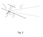
- the present invention relates to a method and a sensor system 1, as illustrated in figure 2 , for reducing the surface area and volume requirements for window mounted optical sensors 2 for motor vehicles.
- a method and a sensor system 1 are provided herein to improve the implementation of optical sensor systems that are designed to acquire optical information through windowpanes 3 in vehicles.
- the system 1 may be configured to be used in the sloped windshields 3 of vehicles to provide optical information 4 of what lies ahead of the vehicle, or alternatively configured to be used with the side windows, to provide optical information on what is present at the sides of or even behind the vehicle.
- the invention is based in the realization that the sight-cone 4 of optical sensors 2 may be reduced through refracting the optical path 4 at the interface between the glass pane 3 and the ambient air.
- the present invention is in a first embodiment based on the use of a thin transparent film 5 and in a second embodiment based on the use of either of a machined or casted area 5 at the inside surface of the windowpane 3.
- this refractive transparent area 5 at the inside surface of the windowpane 3 has a Fresnel lens surface or alternatively a surface of light refracting prisms arranged in a pattern which corrects any possible distortion of the passage of light through the air/film/glass interface, or alternatively distorts in such a way that subsequent image processing easily may correct any errors caused thereby.
- the refractive transparent area 5 may be arranged at the inside of the glass pane 3 of the windshield 3, where it will be protected from any outside weather conditions and resulting fouling.
- a method to reduce the area and volume requirements and optimize transmission for window 3 mounted optical sensors 2 for motor vehicles comprises the steps of: arranging an optical sensor 2 on the inner side of a windowpane 3 of the motor vehicle to condense light 4 coming from an object to be detected that is located outside the windowpane 3 of the motor vehicle and to obtain information from the light 4 that has been thus condensed; and providing a refractive transparent area 5 at the inside surface of the windowpane 3 between the windowpane 3 and the optical sensor 2 to refract the light 4 from the object to be detected that has passed through the windowpane 3.
- the method further comprises the step of providing the refractive transparent area 5 at the inside surface of the windowpane 3 through the application thereto of a refractive transparent film 5.
- the method further comprises the step of providing the refractive transparent area 5 at the inside surface of the windowpane 3 as a Fresnel lens, where the Fresnel lens is arranged at the refractive transparent film 5.
- the method further comprises the step of providing the refractive transparent area 5 at the inside surface of the windowpane 3 as a plurality of micro-prisms, where the plurality of micro-prisms are arranged at the refractive transparent film 5.
- the method further comprises the step of attaching the transparent refractive film 5 to the windowpane 3 by a light transmitting adhesive agent.
- the method comprises the step of providing the refractive transparent area 5 at the inside surface of the windowpane 3 through either machining the area 5 at the inside surface of the windowpane 3 or through casting the windowpane 3 using a casting tool arranged to provide the refractive transparent area 5 at the inside surface of the windowpane 3.
- the method further comprises the step of providing the refractive transparent area 5 at the inside surface of the windowpane 3 as a Fresnel lens, where the Fresnel lens is either machined from or casted at the inside surface 5 of the windowpane 3.
- the method further comprises the step of providing the refractive transparent area 5 at the inside surface of the windowpane 3 as a plurality of micro-prisms, where the plurality of micro-prisms are either machined from or casted at the inside surface 5 of the windowpane 3.
- the film 5 and machined or casted area 5 adds essentially no thickness to the windowpane 3 it becomes possible to reduce the area and volume requirements and optimize transmission for window 3 mounted optical sensors 2 for motor vehicles. Furthermore, it thus becomes possible to achieve more space effective packaging of the optical sensor system 1 in closer proximity to the windowpane 3 than with the prior art arrangements.
- the present invention also relates to a window 3 mounted sensor system 1 for motor vehicles comprising an optical sensor 2, such as a camera, arranged on the inner side of a windowpane 3 of the motor vehicle to condense light 4 coming from an object to be detected that is located outside the windowpane 3 of the motor vehicle and to obtain information from the light 4 that has been thus condensed.
- the window 3 mounted sensor system 1 comprises a refractive transparent area 5 provided at the inside surface of the windowpane 3 between the windowpane 3 and the optical sensor 2 to refract the light 4 from the object to be detected that has passed through the windowpane 3.
- the system 1 further comprises that the refractive transparent area 5 at the inside surface of the windowpane 3 is provided by a refractive transparent film 5 attached thereto.
- the thin nature of the transparent refractive film 5 facilitates to optimize the packaging of the sensor system 1 in proximity to the windowpane 3.
- the transparent refractive film 5 is of optically transparent material and preferably a plastic film. It is possible, therefore, to acquire the transparent refractive film 5 at low cost. Furthermore, such a transparent refractive film 5 will be flexible and thus it will be possible to use it to achieve a perfect fit, even to a curved windowpane 3.
- the sensor system 1 further comprises that the refractive transparent area 5 at the inside surface of the windowpane 3 is provided as a Fresnel lens, where the Fresnel lens is arranged at the refractive transparent film 5.
- the sensor system 1 further comprises that the refractive transparent area 5 at the inside surface of the windowpane 3 is provided as a plurality of micro-prisms, where the plurality of micro-prisms are arranged at the refractive transparent film 5.
- the sensor system 1 further comprises that the transparent refractive film 5 is attached to the windowpane 3 by a light transmitting adhesive agent.
- a light transmitting adhesive agent Preferably, an adhesive with an index of refraction substantially similar to the windowpane 3 is used to mount the transparent refractive film 5 to the windowpane 3.
- Fig. 2 is a general schematic view of an exemplary optical sensor system 1 in accordance with the first embodiment, as described above.
- the optical sensor system 1 makes use of the transparent refractive film 5 that "bends" light 4 and conveys the light 4 to the optical sensor 2. This configuration minimizes the intrusion of the sensor system 1 into the passenger compartment, and allows for the elimination of external protrusions in providing side/rear views of the vehicle.
- the sensor system 1 comprises that the refractive transparent area 5 at the inside surface of the windowpane 3 is provided by either a machined area 5 at the inside surface of the windowpane 3 or by an area 5 formed when the windowpane 3 was casted by the use of a casting tool arranged to provide the refractive transparent area 5 at the inside surface of the windowpane 3.
- the sensor system 1 further comprises that the refractive transparent area 5 at the inside surface of the windowpane 3 is provided as a Fresnel lens, where the Fresnel lens is either machined from or casted at the inside surface 5 of the windowpane 3.
- the sensor system 1 further comprises that the refractive transparent area 5 at the inside surface of the windowpane 3 is provided as a plurality of micro-prisms, where the plurality of micro-prisms are either machined from or casted at the inside surface 5 of the windowpane 3.
- the present invention also relates to an automotive vehicle, which comprises a window 3 mounted optical sensor system 1 for motor vehicles as described above.
- the present invention also relates to a transparent refractive film 5 for a window 3 mounted optical sensor system 1 for motor vehicles as described above which comprises: a light-entrance surface configured to be attached to an inside surface of a windowpane 3 of a motor vehicle; and a light-exit surface configured to be facing an optical sensor 2 arranged on the inner side of a windowpane 3 of the motor vehicle; and the transparent refractive film being 5 configured to refract an optical path of light 4 by means of at least one of a Fresnel lens and a plurality of micro-prisms.
- the transparent refractive film 5 may thus be provided for refracting the optical path of light 4 corresponding to an imaged area outside of a vehicle and to direct the light 4 to an optical sensor 2 arranged within the vehicle.
- the transparent refractive film 5 includes the light-entrance surface for mounting to the windowpane 3 of the vehicle and the light-exit surface configured to be facing the optical sensor 2 arranged on the inner side of the windowpane 3 of the motor vehicle.
- the transparent refractive film 5 minimizes the possibility that contaminants may accumulate in the optical path of light corresponding to the imaged area as the light 4 travels from the imaged area to the optical sensor 2. Further, the transparent refractive film 5 minimizes the footprint of the system 1 and reduces the surface area on the outside surface of the windowpane 3 that must be kept clean.
- transparent refractive films 5 may reduce or eliminate the need for external protrusions for viewing an imaged area, such as side-view areas. Accordingly, the transparent refractive film 5 in accordance with the present invention may be used in several applications, including frontal sensor systems and side view sensor systems.
- the optical path 4 of the sensor system 1 may be reduced to the surface area of the refractive transparent area 5 at the inside surface of the windowpane 3.
- This surface area B may, as shown in figure 2 , be smaller than the surface area that must otherwise be kept clean, such as the prior art surface area A shown in Fig. 1 .
- optical path of light 4 according to the present optical sensor system 1 may be placed closer to a viewer's field of view without placing the system 1 within the viewer's field of view. As a result, the overall footprint, or the entire space occupied by the system 1, may thereby be reduced.
- the windowpanes 3 need only be transparent to the wavelengths of interest to the optical sensor system 1.
- the sensor system 1 is only sensing wavelengths in the near infrared-light that is not detectable by a human observer, (e.g. 700nm-1100nm) then the windowpanes 3 could be substantially opaque to a person viewing the windowpanes 3, yet still be transmissive to the light 4 that is being sensed through the windowpanes 3.
- the system 1 should preferably be provided with a light shielding/absorbing means (not shown) for blocking or absorbing unwanted light coming from other than an object to be detected.
- the light shielding/absorbing means blocks or absorbs unwanted light rays, e.g., direct sunlight rays, thereby making it possible to obtain quality images free of ghost or flare.
- a method and system in accordance with the present invention can also be applied where the optical sensors are replaced with window mounted light sources, such as modulated light sources or laser light sources, arranged at the inside of the window for illuminating an area outside of the vehicle.
- window mounted light sources such as modulated light sources or laser light sources
Priority Applications (1)
| Application Number | Priority Date | Filing Date | Title |
|---|---|---|---|
| EP10164444.1A EP2390141B1 (de) | 2010-05-31 | 2010-05-31 | Optische Sensorschnittstelle |
Applications Claiming Priority (1)
| Application Number | Priority Date | Filing Date | Title |
|---|---|---|---|
| EP10164444.1A EP2390141B1 (de) | 2010-05-31 | 2010-05-31 | Optische Sensorschnittstelle |
Publications (2)
| Publication Number | Publication Date |
|---|---|
| EP2390141A1 true EP2390141A1 (de) | 2011-11-30 |
| EP2390141B1 EP2390141B1 (de) | 2014-09-24 |
Family
ID=43048922
Family Applications (1)
| Application Number | Title | Priority Date | Filing Date |
|---|---|---|---|
| EP10164444.1A Active EP2390141B1 (de) | 2010-05-31 | 2010-05-31 | Optische Sensorschnittstelle |
Country Status (1)
| Country | Link |
|---|---|
| EP (1) | EP2390141B1 (de) |
Cited By (4)
| Publication number | Priority date | Publication date | Assignee | Title |
|---|---|---|---|---|
| DE102013210887A1 (de) * | 2013-06-11 | 2014-12-11 | Robert Bosch Gmbh | Optische Sensoranordnung für ein Fahrzeug und Fahrzeug mit einer derartigen Sensoranordnung |
| FR3057499A1 (fr) * | 2016-10-17 | 2018-04-20 | Saint-Gobain Glass France | Pare-brise d'aide a la conduite |
| WO2018087223A1 (de) * | 2016-11-14 | 2018-05-17 | Saint-Gobain Glass France | Fahrzeugscheibe mit lichtleitkörper für einen sensor |
| US10960646B2 (en) * | 2016-04-27 | 2021-03-30 | AGC Inc. | Window member and vehicle window glass |
Citations (9)
| Publication number | Priority date | Publication date | Assignee | Title |
|---|---|---|---|---|
| DE19706043A1 (de) * | 1996-12-12 | 1998-06-18 | Brose Fahrzeugteile | Kunststoffscheibe für eine Kraftfahrzeugtür |
| DE19805000A1 (de) * | 1998-02-07 | 1999-08-12 | Opel Adam Ag | Optische Sensorvorrichtung für Kraftfahrzeuge |
| US6108141A (en) * | 1997-06-29 | 2000-08-22 | Gadberry; John W. | Signal viewing device |
| US6768092B2 (en) | 2001-07-13 | 2004-07-27 | Mitsubishi Denki Kabushiki Kaisha | Sensor in car window |
| EP1627773A1 (de) | 2004-08-16 | 2006-02-22 | Delphi Technologies, Inc. | Lichtbrechender Block und Bildaufnahmesysteme |
| WO2006064166A1 (fr) * | 2004-12-17 | 2006-06-22 | Saint-Gobain Glass France | Systeme de vision indirect permettant de minimiser les angles morts sans distorsion de l'image formee |
| DE102006008272A1 (de) * | 2006-02-22 | 2007-08-23 | Siemens Ag | Kraftfahrzeug mit einer optischen Erfassungsvorrichtung |
| DE102008020954A1 (de) * | 2008-04-25 | 2009-10-29 | Ifm Electronic Gmbh | Kameraanordnung für ein Kraftfahrzeug |
| WO2010121982A1 (de) * | 2009-04-23 | 2010-10-28 | Saint-Gobain Glass France | Fahrzeugverglasung, verfahren zu dessen herstellung und verwendung |
-
2010
- 2010-05-31 EP EP10164444.1A patent/EP2390141B1/de active Active
Patent Citations (9)
| Publication number | Priority date | Publication date | Assignee | Title |
|---|---|---|---|---|
| DE19706043A1 (de) * | 1996-12-12 | 1998-06-18 | Brose Fahrzeugteile | Kunststoffscheibe für eine Kraftfahrzeugtür |
| US6108141A (en) * | 1997-06-29 | 2000-08-22 | Gadberry; John W. | Signal viewing device |
| DE19805000A1 (de) * | 1998-02-07 | 1999-08-12 | Opel Adam Ag | Optische Sensorvorrichtung für Kraftfahrzeuge |
| US6768092B2 (en) | 2001-07-13 | 2004-07-27 | Mitsubishi Denki Kabushiki Kaisha | Sensor in car window |
| EP1627773A1 (de) | 2004-08-16 | 2006-02-22 | Delphi Technologies, Inc. | Lichtbrechender Block und Bildaufnahmesysteme |
| WO2006064166A1 (fr) * | 2004-12-17 | 2006-06-22 | Saint-Gobain Glass France | Systeme de vision indirect permettant de minimiser les angles morts sans distorsion de l'image formee |
| DE102006008272A1 (de) * | 2006-02-22 | 2007-08-23 | Siemens Ag | Kraftfahrzeug mit einer optischen Erfassungsvorrichtung |
| DE102008020954A1 (de) * | 2008-04-25 | 2009-10-29 | Ifm Electronic Gmbh | Kameraanordnung für ein Kraftfahrzeug |
| WO2010121982A1 (de) * | 2009-04-23 | 2010-10-28 | Saint-Gobain Glass France | Fahrzeugverglasung, verfahren zu dessen herstellung und verwendung |
Cited By (9)
| Publication number | Priority date | Publication date | Assignee | Title |
|---|---|---|---|---|
| DE102013210887A1 (de) * | 2013-06-11 | 2014-12-11 | Robert Bosch Gmbh | Optische Sensoranordnung für ein Fahrzeug und Fahrzeug mit einer derartigen Sensoranordnung |
| DE102013210887B4 (de) | 2013-06-11 | 2019-12-12 | Robert Bosch Gmbh | Optische Sensoranordnung für ein Fahrzeug und Fahrzeug mit einer derartigen Sensoranordnung |
| US10960646B2 (en) * | 2016-04-27 | 2021-03-30 | AGC Inc. | Window member and vehicle window glass |
| FR3057499A1 (fr) * | 2016-10-17 | 2018-04-20 | Saint-Gobain Glass France | Pare-brise d'aide a la conduite |
| WO2018073528A1 (fr) * | 2016-10-17 | 2018-04-26 | Saint-Gobain Glass France | Pare-brise d'aide a la conduite |
| US10899286B2 (en) | 2016-10-17 | 2021-01-26 | Saint-Gobain Glass France | Windscreen for driving assistance |
| EP3526065B1 (de) * | 2016-10-17 | 2023-08-02 | Saint-Gobain Glass France | Windschutzscheibe für fahrhilfe |
| WO2018087223A1 (de) * | 2016-11-14 | 2018-05-17 | Saint-Gobain Glass France | Fahrzeugscheibe mit lichtleitkörper für einen sensor |
| US10703253B2 (en) | 2016-11-14 | 2020-07-07 | Saint-Gobain Glass France | Vehicle window with light guide body for a sensor |
Also Published As
| Publication number | Publication date |
|---|---|
| EP2390141B1 (de) | 2014-09-24 |
Similar Documents
| Publication | Publication Date | Title |
|---|---|---|
| EP1627773B1 (de) | Lichtbrechender Block und Bildaufnahmesysteme | |
| US8913133B2 (en) | Camera system for a motor vehicle, and motor vehicle equipped with a camera system | |
| JP5382476B2 (ja) | 画像において遠隔範囲及び近接範囲を検出する多焦点レンズを持つ光学モジュール | |
| US6768092B2 (en) | Sensor in car window | |
| US7811011B2 (en) | Camera arrangement behind an inclined pane | |
| US7310190B2 (en) | Vehicle imaging system with windshield condition determination | |
| US9676329B2 (en) | Camera system and method for operating a camera system for a motor vehicle | |
| EP2562051A1 (de) | Optische Brechungsvorrichtung und Abbildungssystem | |
| EP2390141B1 (de) | Optische Sensorschnittstelle | |
| FR2947781A1 (fr) | Dispositif de saisie de donnees d'image pour un vehicule automobile | |
| US10106102B2 (en) | Camera assembly for a vehicle, and vehicle having such a camera assembly | |
| KR102472620B1 (ko) | 운전 보조를 위한 윈드스크린 | |
| CN108696676B (zh) | 相机模块 | |
| JP2012163875A (ja) | レンズ固定構造、及びそれを用いた広角撮像装置 | |
| US11714279B2 (en) | Vehicle display device | |
| WO2021182290A1 (ja) | 車両用ガラス、枠部材及び車両用ガラスの製造方法 | |
| CN112859332B (zh) | 用于平视显示器(hud)的遮光膜和用于车辆的hud系统 | |
| EP2766227B1 (de) | Kameraanordnung | |
| US7475932B2 (en) | Windscreen | |
| KR20150000095A (ko) | 헤드업 디스플레이 장치 및 라이다 센서를 위한 윈드 실드 | |
| US20200025978A1 (en) | Optical device cover | |
| US20230105712A1 (en) | Athermalized lens design | |
| CN114126924A (zh) | 车辆用外饰件以及带有远红外摄像头的车辆用外饰件 | |
| JP2004343379A (ja) | 撮像装置及び撮像装置の製造方法、車両用周辺撮像装置 |
Legal Events
| Date | Code | Title | Description |
|---|---|---|---|
| AK | Designated contracting states |
Kind code of ref document: A1 Designated state(s): AL AT BE BG CH CY CZ DE DK EE ES FI FR GB GR HR HU IE IS IT LI LT LU LV MC MK MT NL NO PL PT RO SE SI SK SM TR |
|
| AX | Request for extension of the european patent |
Extension state: BA ME RS |
|
| PUAI | Public reference made under article 153(3) epc to a published international application that has entered the european phase |
Free format text: ORIGINAL CODE: 0009012 |
|
| 17P | Request for examination filed |
Effective date: 20120530 |
|
| 17Q | First examination report despatched |
Effective date: 20120718 |
|
| GRAP | Despatch of communication of intention to grant a patent |
Free format text: ORIGINAL CODE: EPIDOSNIGR1 |
|
| INTG | Intention to grant announced |
Effective date: 20140424 |
|
| GRAS | Grant fee paid |
Free format text: ORIGINAL CODE: EPIDOSNIGR3 |
|
| GRAA | (expected) grant |
Free format text: ORIGINAL CODE: 0009210 |
|
| AK | Designated contracting states |
Kind code of ref document: B1 Designated state(s): AL AT BE BG CH CY CZ DE DK EE ES FI FR GB GR HR HU IE IS IT LI LT LU LV MC MK MT NL NO PL PT RO SE SI SK SM TR |
|
| REG | Reference to a national code |
Ref country code: GB Ref legal event code: FG4D |
|
| REG | Reference to a national code |
Ref country code: CH Ref legal event code: EP |
|
| REG | Reference to a national code |
Ref country code: AT Ref legal event code: REF Ref document number: 688458 Country of ref document: AT Kind code of ref document: T Effective date: 20141015 |
|
| REG | Reference to a national code |
Ref country code: IE Ref legal event code: FG4D |
|
| REG | Reference to a national code |
Ref country code: DE Ref legal event code: R096 Ref document number: 602010019099 Country of ref document: DE Effective date: 20141106 |
|
| REG | Reference to a national code |
Ref country code: SE Ref legal event code: TRGR |
|
| PG25 | Lapsed in a contracting state [announced via postgrant information from national office to epo] |
Ref country code: GR Free format text: LAPSE BECAUSE OF FAILURE TO SUBMIT A TRANSLATION OF THE DESCRIPTION OR TO PAY THE FEE WITHIN THE PRESCRIBED TIME-LIMIT Effective date: 20141225 Ref country code: FI Free format text: LAPSE BECAUSE OF FAILURE TO SUBMIT A TRANSLATION OF THE DESCRIPTION OR TO PAY THE FEE WITHIN THE PRESCRIBED TIME-LIMIT Effective date: 20140924 Ref country code: LT Free format text: LAPSE BECAUSE OF FAILURE TO SUBMIT A TRANSLATION OF THE DESCRIPTION OR TO PAY THE FEE WITHIN THE PRESCRIBED TIME-LIMIT Effective date: 20140924 Ref country code: NO Free format text: LAPSE BECAUSE OF FAILURE TO SUBMIT A TRANSLATION OF THE DESCRIPTION OR TO PAY THE FEE WITHIN THE PRESCRIBED TIME-LIMIT Effective date: 20141224 |
|
| REG | Reference to a national code |
Ref country code: LT Ref legal event code: MG4D Ref country code: NL Ref legal event code: VDEP Effective date: 20140924 |
|
| PG25 | Lapsed in a contracting state [announced via postgrant information from national office to epo] |
Ref country code: LV Free format text: LAPSE BECAUSE OF FAILURE TO SUBMIT A TRANSLATION OF THE DESCRIPTION OR TO PAY THE FEE WITHIN THE PRESCRIBED TIME-LIMIT Effective date: 20140924 Ref country code: HR Free format text: LAPSE BECAUSE OF FAILURE TO SUBMIT A TRANSLATION OF THE DESCRIPTION OR TO PAY THE FEE WITHIN THE PRESCRIBED TIME-LIMIT Effective date: 20140924 Ref country code: CY Free format text: LAPSE BECAUSE OF FAILURE TO SUBMIT A TRANSLATION OF THE DESCRIPTION OR TO PAY THE FEE WITHIN THE PRESCRIBED TIME-LIMIT Effective date: 20140924 |
|
| REG | Reference to a national code |
Ref country code: AT Ref legal event code: MK05 Ref document number: 688458 Country of ref document: AT Kind code of ref document: T Effective date: 20140924 |
|
| PG25 | Lapsed in a contracting state [announced via postgrant information from national office to epo] |
Ref country code: NL Free format text: LAPSE BECAUSE OF FAILURE TO SUBMIT A TRANSLATION OF THE DESCRIPTION OR TO PAY THE FEE WITHIN THE PRESCRIBED TIME-LIMIT Effective date: 20140924 |
|
| PG25 | Lapsed in a contracting state [announced via postgrant information from national office to epo] |
Ref country code: ES Free format text: LAPSE BECAUSE OF FAILURE TO SUBMIT A TRANSLATION OF THE DESCRIPTION OR TO PAY THE FEE WITHIN THE PRESCRIBED TIME-LIMIT Effective date: 20140924 Ref country code: SK Free format text: LAPSE BECAUSE OF FAILURE TO SUBMIT A TRANSLATION OF THE DESCRIPTION OR TO PAY THE FEE WITHIN THE PRESCRIBED TIME-LIMIT Effective date: 20140924 Ref country code: PT Free format text: LAPSE BECAUSE OF FAILURE TO SUBMIT A TRANSLATION OF THE DESCRIPTION OR TO PAY THE FEE WITHIN THE PRESCRIBED TIME-LIMIT Effective date: 20150126 Ref country code: IS Free format text: LAPSE BECAUSE OF FAILURE TO SUBMIT A TRANSLATION OF THE DESCRIPTION OR TO PAY THE FEE WITHIN THE PRESCRIBED TIME-LIMIT Effective date: 20150124 Ref country code: CZ Free format text: LAPSE BECAUSE OF FAILURE TO SUBMIT A TRANSLATION OF THE DESCRIPTION OR TO PAY THE FEE WITHIN THE PRESCRIBED TIME-LIMIT Effective date: 20140924 Ref country code: RO Free format text: LAPSE BECAUSE OF FAILURE TO SUBMIT A TRANSLATION OF THE DESCRIPTION OR TO PAY THE FEE WITHIN THE PRESCRIBED TIME-LIMIT Effective date: 20140924 Ref country code: EE Free format text: LAPSE BECAUSE OF FAILURE TO SUBMIT A TRANSLATION OF THE DESCRIPTION OR TO PAY THE FEE WITHIN THE PRESCRIBED TIME-LIMIT Effective date: 20140924 |
|
| PG25 | Lapsed in a contracting state [announced via postgrant information from national office to epo] |
Ref country code: AT Free format text: LAPSE BECAUSE OF FAILURE TO SUBMIT A TRANSLATION OF THE DESCRIPTION OR TO PAY THE FEE WITHIN THE PRESCRIBED TIME-LIMIT Effective date: 20140924 Ref country code: PL Free format text: LAPSE BECAUSE OF FAILURE TO SUBMIT A TRANSLATION OF THE DESCRIPTION OR TO PAY THE FEE WITHIN THE PRESCRIBED TIME-LIMIT Effective date: 20140924 |
|
| REG | Reference to a national code |
Ref country code: DE Ref legal event code: R097 Ref document number: 602010019099 Country of ref document: DE |
|
| PG25 | Lapsed in a contracting state [announced via postgrant information from national office to epo] |
Ref country code: DK Free format text: LAPSE BECAUSE OF FAILURE TO SUBMIT A TRANSLATION OF THE DESCRIPTION OR TO PAY THE FEE WITHIN THE PRESCRIBED TIME-LIMIT Effective date: 20140924 |
|
| PLBE | No opposition filed within time limit |
Free format text: ORIGINAL CODE: 0009261 |
|
| STAA | Information on the status of an ep patent application or granted ep patent |
Free format text: STATUS: NO OPPOSITION FILED WITHIN TIME LIMIT |
|
| PG25 | Lapsed in a contracting state [announced via postgrant information from national office to epo] |
Ref country code: IT Free format text: LAPSE BECAUSE OF FAILURE TO SUBMIT A TRANSLATION OF THE DESCRIPTION OR TO PAY THE FEE WITHIN THE PRESCRIBED TIME-LIMIT Effective date: 20140924 |
|
| 26N | No opposition filed |
Effective date: 20150625 |
|
| REG | Reference to a national code |
Ref country code: CH Ref legal event code: PL |
|
| PG25 | Lapsed in a contracting state [announced via postgrant information from national office to epo] |
Ref country code: LI Free format text: LAPSE BECAUSE OF NON-PAYMENT OF DUE FEES Effective date: 20150531 Ref country code: MC Free format text: LAPSE BECAUSE OF FAILURE TO SUBMIT A TRANSLATION OF THE DESCRIPTION OR TO PAY THE FEE WITHIN THE PRESCRIBED TIME-LIMIT Effective date: 20140924 Ref country code: CH Free format text: LAPSE BECAUSE OF NON-PAYMENT OF DUE FEES Effective date: 20150531 Ref country code: LU Free format text: LAPSE BECAUSE OF FAILURE TO SUBMIT A TRANSLATION OF THE DESCRIPTION OR TO PAY THE FEE WITHIN THE PRESCRIBED TIME-LIMIT Effective date: 20150531 |
|
| REG | Reference to a national code |
Ref country code: IE Ref legal event code: MM4A |
|
| REG | Reference to a national code |
Ref country code: FR Ref legal event code: ST Effective date: 20160129 |
|
| PG25 | Lapsed in a contracting state [announced via postgrant information from national office to epo] |
Ref country code: SI Free format text: LAPSE BECAUSE OF FAILURE TO SUBMIT A TRANSLATION OF THE DESCRIPTION OR TO PAY THE FEE WITHIN THE PRESCRIBED TIME-LIMIT Effective date: 20140924 |
|
| PG25 | Lapsed in a contracting state [announced via postgrant information from national office to epo] |
Ref country code: IE Free format text: LAPSE BECAUSE OF NON-PAYMENT OF DUE FEES Effective date: 20150531 |
|
| PG25 | Lapsed in a contracting state [announced via postgrant information from national office to epo] |
Ref country code: FR Free format text: LAPSE BECAUSE OF NON-PAYMENT OF DUE FEES Effective date: 20150601 |
|
| PG25 | Lapsed in a contracting state [announced via postgrant information from national office to epo] |
Ref country code: MT Free format text: LAPSE BECAUSE OF FAILURE TO SUBMIT A TRANSLATION OF THE DESCRIPTION OR TO PAY THE FEE WITHIN THE PRESCRIBED TIME-LIMIT Effective date: 20140924 |
|
| PG25 | Lapsed in a contracting state [announced via postgrant information from national office to epo] |
Ref country code: BG Free format text: LAPSE BECAUSE OF FAILURE TO SUBMIT A TRANSLATION OF THE DESCRIPTION OR TO PAY THE FEE WITHIN THE PRESCRIBED TIME-LIMIT Effective date: 20140924 Ref country code: HU Free format text: LAPSE BECAUSE OF FAILURE TO SUBMIT A TRANSLATION OF THE DESCRIPTION OR TO PAY THE FEE WITHIN THE PRESCRIBED TIME-LIMIT; INVALID AB INITIO Effective date: 20100531 Ref country code: SM Free format text: LAPSE BECAUSE OF FAILURE TO SUBMIT A TRANSLATION OF THE DESCRIPTION OR TO PAY THE FEE WITHIN THE PRESCRIBED TIME-LIMIT Effective date: 20140924 |
|
| PG25 | Lapsed in a contracting state [announced via postgrant information from national office to epo] |
Ref country code: TR Free format text: LAPSE BECAUSE OF FAILURE TO SUBMIT A TRANSLATION OF THE DESCRIPTION OR TO PAY THE FEE WITHIN THE PRESCRIBED TIME-LIMIT Effective date: 20140924 |
|
| PG25 | Lapsed in a contracting state [announced via postgrant information from national office to epo] |
Ref country code: BE Free format text: LAPSE BECAUSE OF FAILURE TO SUBMIT A TRANSLATION OF THE DESCRIPTION OR TO PAY THE FEE WITHIN THE PRESCRIBED TIME-LIMIT Effective date: 20140924 |
|
| PG25 | Lapsed in a contracting state [announced via postgrant information from national office to epo] |
Ref country code: MK Free format text: LAPSE BECAUSE OF FAILURE TO SUBMIT A TRANSLATION OF THE DESCRIPTION OR TO PAY THE FEE WITHIN THE PRESCRIBED TIME-LIMIT Effective date: 20140924 |
|
| PG25 | Lapsed in a contracting state [announced via postgrant information from national office to epo] |
Ref country code: AL Free format text: LAPSE BECAUSE OF FAILURE TO SUBMIT A TRANSLATION OF THE DESCRIPTION OR TO PAY THE FEE WITHIN THE PRESCRIBED TIME-LIMIT Effective date: 20140924 |
|
| PGFP | Annual fee paid to national office [announced via postgrant information from national office to epo] |
Ref country code: SE Payment date: 20210421 Year of fee payment: 12 |
|
| REG | Reference to a national code |
Ref country code: SE Ref legal event code: EUG |
|
| PG25 | Lapsed in a contracting state [announced via postgrant information from national office to epo] |
Ref country code: SE Free format text: LAPSE BECAUSE OF NON-PAYMENT OF DUE FEES Effective date: 20220601 |
|
| PGFP | Annual fee paid to national office [announced via postgrant information from national office to epo] |
Ref country code: DE Payment date: 20230419 Year of fee payment: 14 |
|
| PGFP | Annual fee paid to national office [announced via postgrant information from national office to epo] |
Ref country code: GB Payment date: 20230420 Year of fee payment: 14 |
|
| P01 | Opt-out of the competence of the unified patent court (upc) registered |
Effective date: 20231212 |