EP2389969A1 - Vorrichtung zum Injizieren einer Substanz - Google Patents
Vorrichtung zum Injizieren einer Substanz Download PDFInfo
- Publication number
- EP2389969A1 EP2389969A1 EP10250976A EP10250976A EP2389969A1 EP 2389969 A1 EP2389969 A1 EP 2389969A1 EP 10250976 A EP10250976 A EP 10250976A EP 10250976 A EP10250976 A EP 10250976A EP 2389969 A1 EP2389969 A1 EP 2389969A1
- Authority
- EP
- European Patent Office
- Prior art keywords
- housing
- needle
- plunger
- plunger base
- injection
- Prior art date
- Legal status (The legal status is an assumption and is not a legal conclusion. Google has not performed a legal analysis and makes no representation as to the accuracy of the status listed.)
- Withdrawn
Links
Images


Classifications
-
- A—HUMAN NECESSITIES
- A61—MEDICAL OR VETERINARY SCIENCE; HYGIENE
- A61B—DIAGNOSIS; SURGERY; IDENTIFICATION
- A61B17/00—Surgical instruments, devices or methods, e.g. tourniquets
- A61B17/00491—Surgical glue applicators
-
- A—HUMAN NECESSITIES
- A61—MEDICAL OR VETERINARY SCIENCE; HYGIENE
- A61M—DEVICES FOR INTRODUCING MEDIA INTO, OR ONTO, THE BODY; DEVICES FOR TRANSDUCING BODY MEDIA OR FOR TAKING MEDIA FROM THE BODY; DEVICES FOR PRODUCING OR ENDING SLEEP OR STUPOR
- A61M5/00—Devices for bringing media into the body in a subcutaneous, intra-vascular or intramuscular way; Accessories therefor, e.g. filling or cleaning devices, arm-rests
- A61M5/178—Syringes
- A61M5/31—Details
- A61M5/32—Needles; Details of needles pertaining to their connection with syringe or hub; Accessories for bringing the needle into, or holding the needle on, the body; Devices for protection of needles
- A61M5/3294—Needles; Details of needles pertaining to their connection with syringe or hub; Accessories for bringing the needle into, or holding the needle on, the body; Devices for protection of needles comprising means for injection of two or more media, e.g. by mixing
-
- A—HUMAN NECESSITIES
- A61—MEDICAL OR VETERINARY SCIENCE; HYGIENE
- A61M—DEVICES FOR INTRODUCING MEDIA INTO, OR ONTO, THE BODY; DEVICES FOR TRANSDUCING BODY MEDIA OR FOR TAKING MEDIA FROM THE BODY; DEVICES FOR PRODUCING OR ENDING SLEEP OR STUPOR
- A61M5/00—Devices for bringing media into the body in a subcutaneous, intra-vascular or intramuscular way; Accessories therefor, e.g. filling or cleaning devices, arm-rests
- A61M5/178—Syringes
- A61M5/19—Syringes having more than one chamber, e.g. including a manifold coupling two parallelly aligned syringes through separate channels to a common discharge assembly
-
- A—HUMAN NECESSITIES
- A61—MEDICAL OR VETERINARY SCIENCE; HYGIENE
- A61M—DEVICES FOR INTRODUCING MEDIA INTO, OR ONTO, THE BODY; DEVICES FOR TRANSDUCING BODY MEDIA OR FOR TAKING MEDIA FROM THE BODY; DEVICES FOR PRODUCING OR ENDING SLEEP OR STUPOR
- A61M5/00—Devices for bringing media into the body in a subcutaneous, intra-vascular or intramuscular way; Accessories therefor, e.g. filling or cleaning devices, arm-rests
- A61M5/178—Syringes
- A61M5/24—Ampoule syringes, i.e. syringes with needle for use in combination with replaceable ampoules or carpules, e.g. automatic
- A61M5/2448—Ampoule syringes, i.e. syringes with needle for use in combination with replaceable ampoules or carpules, e.g. automatic comprising means for injection of two or more media, e.g. by mixing
-
- A—HUMAN NECESSITIES
- A61—MEDICAL OR VETERINARY SCIENCE; HYGIENE
- A61M—DEVICES FOR INTRODUCING MEDIA INTO, OR ONTO, THE BODY; DEVICES FOR TRANSDUCING BODY MEDIA OR FOR TAKING MEDIA FROM THE BODY; DEVICES FOR PRODUCING OR ENDING SLEEP OR STUPOR
- A61M5/00—Devices for bringing media into the body in a subcutaneous, intra-vascular or intramuscular way; Accessories therefor, e.g. filling or cleaning devices, arm-rests
- A61M5/178—Syringes
- A61M5/31—Details
- A61M5/315—Pistons; Piston-rods; Guiding, blocking or restricting the movement of the rod or piston; Appliances on the rod for facilitating dosing ; Dosing mechanisms
- A61M5/31565—Administration mechanisms, i.e. constructional features, modes of administering a dose
- A61M5/31576—Constructional features or modes of drive mechanisms for piston rods
- A61M5/31578—Constructional features or modes of drive mechanisms for piston rods based on axial translation, i.e. components directly operatively associated and axially moved with plunger rod
- A61M5/31581—Constructional features or modes of drive mechanisms for piston rods based on axial translation, i.e. components directly operatively associated and axially moved with plunger rod performed by rotationally moving or pivoting actuator operated by user, e.g. an injection lever or handle
-
- A—HUMAN NECESSITIES
- A61—MEDICAL OR VETERINARY SCIENCE; HYGIENE
- A61M—DEVICES FOR INTRODUCING MEDIA INTO, OR ONTO, THE BODY; DEVICES FOR TRANSDUCING BODY MEDIA OR FOR TAKING MEDIA FROM THE BODY; DEVICES FOR PRODUCING OR ENDING SLEEP OR STUPOR
- A61M5/00—Devices for bringing media into the body in a subcutaneous, intra-vascular or intramuscular way; Accessories therefor, e.g. filling or cleaning devices, arm-rests
- A61M5/178—Syringes
- A61M5/31—Details
- A61M5/315—Pistons; Piston-rods; Guiding, blocking or restricting the movement of the rod or piston; Appliances on the rod for facilitating dosing ; Dosing mechanisms
- A61M5/31596—Pistons; Piston-rods; Guiding, blocking or restricting the movement of the rod or piston; Appliances on the rod for facilitating dosing ; Dosing mechanisms comprising means for injection of two or more media, e.g. by mixing
-
- A—HUMAN NECESSITIES
- A61—MEDICAL OR VETERINARY SCIENCE; HYGIENE
- A61M—DEVICES FOR INTRODUCING MEDIA INTO, OR ONTO, THE BODY; DEVICES FOR TRANSDUCING BODY MEDIA OR FOR TAKING MEDIA FROM THE BODY; DEVICES FOR PRODUCING OR ENDING SLEEP OR STUPOR
- A61M5/00—Devices for bringing media into the body in a subcutaneous, intra-vascular or intramuscular way; Accessories therefor, e.g. filling or cleaning devices, arm-rests
- A61M5/178—Syringes
- A61M5/31—Details
- A61M5/32—Needles; Details of needles pertaining to their connection with syringe or hub; Accessories for bringing the needle into, or holding the needle on, the body; Devices for protection of needles
- A61M5/3205—Apparatus for removing or disposing of used needles or syringes, e.g. containers; Means for protection against accidental injuries from used needles
- A61M5/321—Means for protection against accidental injuries by used needles
- A61M5/322—Retractable needles, i.e. disconnected from and withdrawn into the syringe barrel by the piston
-
- A—HUMAN NECESSITIES
- A61—MEDICAL OR VETERINARY SCIENCE; HYGIENE
- A61M—DEVICES FOR INTRODUCING MEDIA INTO, OR ONTO, THE BODY; DEVICES FOR TRANSDUCING BODY MEDIA OR FOR TAKING MEDIA FROM THE BODY; DEVICES FOR PRODUCING OR ENDING SLEEP OR STUPOR
- A61M5/00—Devices for bringing media into the body in a subcutaneous, intra-vascular or intramuscular way; Accessories therefor, e.g. filling or cleaning devices, arm-rests
- A61M5/178—Syringes
- A61M5/31—Details
- A61M5/32—Needles; Details of needles pertaining to their connection with syringe or hub; Accessories for bringing the needle into, or holding the needle on, the body; Devices for protection of needles
- A61M5/3205—Apparatus for removing or disposing of used needles or syringes, e.g. containers; Means for protection against accidental injuries from used needles
- A61M5/321—Means for protection against accidental injuries by used needles
- A61M5/3243—Means for protection against accidental injuries by used needles being axially-extensible, e.g. protective sleeves coaxially slidable on the syringe barrel
- A61M5/3257—Semi-automatic sleeve extension, i.e. in which triggering of the sleeve extension requires a deliberate action by the user, e.g. manual release of spring-biased extension means
-
- A—HUMAN NECESSITIES
- A61—MEDICAL OR VETERINARY SCIENCE; HYGIENE
- A61M—DEVICES FOR INTRODUCING MEDIA INTO, OR ONTO, THE BODY; DEVICES FOR TRANSDUCING BODY MEDIA OR FOR TAKING MEDIA FROM THE BODY; DEVICES FOR PRODUCING OR ENDING SLEEP OR STUPOR
- A61M5/00—Devices for bringing media into the body in a subcutaneous, intra-vascular or intramuscular way; Accessories therefor, e.g. filling or cleaning devices, arm-rests
- A61M5/178—Syringes
- A61M5/31—Details
- A61M5/32—Needles; Details of needles pertaining to their connection with syringe or hub; Accessories for bringing the needle into, or holding the needle on, the body; Devices for protection of needles
- A61M5/3287—Accessories for bringing the needle into the body; Automatic needle insertion
-
- A—HUMAN NECESSITIES
- A61—MEDICAL OR VETERINARY SCIENCE; HYGIENE
- A61M—DEVICES FOR INTRODUCING MEDIA INTO, OR ONTO, THE BODY; DEVICES FOR TRANSDUCING BODY MEDIA OR FOR TAKING MEDIA FROM THE BODY; DEVICES FOR PRODUCING OR ENDING SLEEP OR STUPOR
- A61M5/00—Devices for bringing media into the body in a subcutaneous, intra-vascular or intramuscular way; Accessories therefor, e.g. filling or cleaning devices, arm-rests
- A61M5/178—Syringes
- A61M5/31—Details
- A61M5/32—Needles; Details of needles pertaining to their connection with syringe or hub; Accessories for bringing the needle into, or holding the needle on, the body; Devices for protection of needles
- A61M5/3293—Needles; Details of needles pertaining to their connection with syringe or hub; Accessories for bringing the needle into, or holding the needle on, the body; Devices for protection of needles characterised by features of the needle hub
-
- A—HUMAN NECESSITIES
- A61—MEDICAL OR VETERINARY SCIENCE; HYGIENE
- A61M—DEVICES FOR INTRODUCING MEDIA INTO, OR ONTO, THE BODY; DEVICES FOR TRANSDUCING BODY MEDIA OR FOR TAKING MEDIA FROM THE BODY; DEVICES FOR PRODUCING OR ENDING SLEEP OR STUPOR
- A61M5/00—Devices for bringing media into the body in a subcutaneous, intra-vascular or intramuscular way; Accessories therefor, e.g. filling or cleaning devices, arm-rests
- A61M5/178—Syringes
- A61M5/31—Details
- A61M2005/3128—Incorporating one-way valves, e.g. pressure-relief or non-return valves
-
- A—HUMAN NECESSITIES
- A61—MEDICAL OR VETERINARY SCIENCE; HYGIENE
- A61M—DEVICES FOR INTRODUCING MEDIA INTO, OR ONTO, THE BODY; DEVICES FOR TRANSDUCING BODY MEDIA OR FOR TAKING MEDIA FROM THE BODY; DEVICES FOR PRODUCING OR ENDING SLEEP OR STUPOR
- A61M5/00—Devices for bringing media into the body in a subcutaneous, intra-vascular or intramuscular way; Accessories therefor, e.g. filling or cleaning devices, arm-rests
- A61M5/178—Syringes
- A61M5/31—Details
- A61M5/32—Needles; Details of needles pertaining to their connection with syringe or hub; Accessories for bringing the needle into, or holding the needle on, the body; Devices for protection of needles
- A61M5/3205—Apparatus for removing or disposing of used needles or syringes, e.g. containers; Means for protection against accidental injuries from used needles
- A61M2005/3206—Needle or needle hub disconnecting devices forming part of or being attached to the hub or syringe body
-
- A—HUMAN NECESSITIES
- A61—MEDICAL OR VETERINARY SCIENCE; HYGIENE
- A61M—DEVICES FOR INTRODUCING MEDIA INTO, OR ONTO, THE BODY; DEVICES FOR TRANSDUCING BODY MEDIA OR FOR TAKING MEDIA FROM THE BODY; DEVICES FOR PRODUCING OR ENDING SLEEP OR STUPOR
- A61M5/00—Devices for bringing media into the body in a subcutaneous, intra-vascular or intramuscular way; Accessories therefor, e.g. filling or cleaning devices, arm-rests
- A61M5/178—Syringes
- A61M5/20—Automatic syringes, e.g. with automatically actuated piston rod, with automatic needle injection, filling automatically
- A61M5/204—Automatic syringes, e.g. with automatically actuated piston rod, with automatic needle injection, filling automatically connected to external reservoirs for multiple refilling
-
- A—HUMAN NECESSITIES
- A61—MEDICAL OR VETERINARY SCIENCE; HYGIENE
- A61M—DEVICES FOR INTRODUCING MEDIA INTO, OR ONTO, THE BODY; DEVICES FOR TRANSDUCING BODY MEDIA OR FOR TAKING MEDIA FROM THE BODY; DEVICES FOR PRODUCING OR ENDING SLEEP OR STUPOR
- A61M5/00—Devices for bringing media into the body in a subcutaneous, intra-vascular or intramuscular way; Accessories therefor, e.g. filling or cleaning devices, arm-rests
- A61M5/178—Syringes
- A61M5/31—Details
- A61M5/32—Needles; Details of needles pertaining to their connection with syringe or hub; Accessories for bringing the needle into, or holding the needle on, the body; Devices for protection of needles
- A61M5/3205—Apparatus for removing or disposing of used needles or syringes, e.g. containers; Means for protection against accidental injuries from used needles
- A61M5/321—Means for protection against accidental injuries by used needles
- A61M5/3243—Means for protection against accidental injuries by used needles being axially-extensible, e.g. protective sleeves coaxially slidable on the syringe barrel
- A61M5/326—Fully automatic sleeve extension, i.e. in which triggering of the sleeve does not require a deliberate action by the user
-
- A—HUMAN NECESSITIES
- A61—MEDICAL OR VETERINARY SCIENCE; HYGIENE
- A61M—DEVICES FOR INTRODUCING MEDIA INTO, OR ONTO, THE BODY; DEVICES FOR TRANSDUCING BODY MEDIA OR FOR TAKING MEDIA FROM THE BODY; DEVICES FOR PRODUCING OR ENDING SLEEP OR STUPOR
- A61M5/00—Devices for bringing media into the body in a subcutaneous, intra-vascular or intramuscular way; Accessories therefor, e.g. filling or cleaning devices, arm-rests
- A61M5/46—Devices for bringing media into the body in a subcutaneous, intra-vascular or intramuscular way; Accessories therefor, e.g. filling or cleaning devices, arm-rests having means for controlling depth of insertion
Definitions
- the present application generally relates to injections, and more specifically relates to medical devices for administering multiple injections.
- the injected substance includes two or more components.
- the two or more components must be stored separate from one another, but are mixed together immediately prior to injecting the combined components into a tissue.
- diabetic patients often receive injections having two different components that must be separated prior to injection.
- fibrinogen and thrombin may be injected to form a fibrin polymer in-situ so as to induce angiogenesis. Due to the fact that fibrinogen and thrombin will rapidly polymerize upon interaction, it is critical that the two components be maintained apart from one another until applied at the application site.
- Providing injections having two or more components are further complicated by the fact that the dosage requirements vary from patient to patient, or even for the same patient. Attempts to combine the separate components into a final, injectable solution often result in contamination of one or more of the individual components.
- attempts to address the administration of two or more medications in liquid form may require administering multiple injections into a patient, a first injection for the first component and simultaneously a second injection for the second component. Administering multiple injections every time an injection is required is time consuming, may result in improper mixing of components, and may cause tissue damage.
- U.S. Patent No. 4,359,049 to Redl et al. teaches a device that holds two syringes together in a support having a common actuator. The dispensing end of each of the syringes is inserted into a collection manifold where the two separate substances are mixed together. The mixed substances are then dispensed through a common needle inserted into an application site.
- U.S. Patent No. 4,609,371 to Pizzino discloses a device including a dual syringe that provides for the simultaneous or sequential injection of two different injectable liquids.
- the dual syringe includes two barrels, each having a plunger for the injection of a liquid, and a manually operable three-position rotary valve that controls the filling of the syringe and the outflow of the liquid from the syringe.
- the valve has three different positions for enabling the liquid to be dispensed either from the first barrel only, the second barrel only, or both barrels simultaneously.
- EP 1 845 860 for applying a multi-component fluid, especially a multi-component tissue glue, including a plurality of substantially cylindrical supply containers for respectively one component of the fluid to be applied.
- Each supply container has a front end with an out-let opening, a rear end opposite to the front end, and a slidably displaceable piston arranged within the supply container and having a piston rod extending out of the rear end for operating the piston.
- the applicator device includes a manifold having terminal ends with a first port for fluid connection with the front ends of the supply containers.
- the manifold also has internal channels extending from the first ports of the terminal ends to an outlet site.
- the applicator device includes a holding element for holding the supply containers, and a coupling clement extending from the holding element and having a connection end connected to the manifold are provided, whereby the connection end of the coupling element is bonded to the manifold.
- an applicator device that provides for the efficient administration of multiple and sequential injections of a substance including at least two components.
- an applicator device for administering injections that enables a single puncture of a patient's skin to properly inject the two or more components that are mixed together.
- an applicator device that may be easily re-filled with additional quantities of the two or more components.
- an applicator device that is relatively inexpensive to manufacture, safe, and easy to use.
- an applicator device having an injection needle that may be automatically extracted from the patient's skin without the need for the administrator to lift the device upward from the injected surface so that the device allows for multiple injections on a 2-D surface of a tissue while moving the device.
- a device for administering injections comprises an injection actuator (40) having gear teeth (48); a needle housing (88) moveable along an axis and including an outer surface having a rack structure (96), the needle housing having an injection needle (94); at least one gear interconnecting the gear teeth (48) of the injection actuator (40) with the rack structure (96) of the needle housing (88) for advancing the needle housing along the axis from a retracted position to an extended position.
- a device for administering injections comprises at least one syringe barrel; at least one plunger connected with the at least one syringe barrel; a plunger base (78) connected with the at least one plunger and is adapted for reciprocal movement along an axis; a needle housing (88) adapted for reciprocal movement along the axis, the needle housing (88) including at least one catch (140) projecting from an outer surface thereof for selectively coupling the needle housing and the plunger base together for providing simultaneous movement of the needle housing and the plunger base in a first direction along the axis, and at least one catch actuator (142) coupled with the at least one catch (140) for selectively decoupling the needle housing from the plunger base so that the needle housing and the plunger base are capable of moving independently of one another along the axis.
- a device for administering injections comprises an injection actuator (40) having gear teeth (48); a needle housing (88) moveable along an axis and including an outer surface having a rack structure (96), the needle housing having an injection needle (94) capable of moving from a retracted position to an extended position; at least one gear interconnecting the gear teeth (48) of the injection actuator (40) with the rack structure (96) of the needle housing (88) for advancing the needle housing along the axis; at least one syringe barrel; at least one plunger connected with the at least one syringe barrel; a plunger base (78) connected with the at least one plunger and is adapted for reciprocal movement along an axis; at least one catch (140) projecting from an outer surface of the needle housing for selectively coupling the needle housing and the plunger base together for providing simultaneous movement of the needle housing and said plunger base in a first direction along the axis; and at least one catch actuator (142) coupled with the at least one catch (140) for
- a device for administering injections comprises a housing (22) having an upper end (24), a lower end (26) including a bottom surface (58) with an injection needle opening (60), and an axis extending between the upper and lower ends of the housing; an injection needle (94) disposed within the housing for moving along the axis between a retracted position in which the injection needle is disposed within the housing and an extended position in which a distal end of the injection needle extends through the injection needle opening at the bottom surface of the housing; a needle housing (88) having the injection needle (94) projecting therefrom and including an outer surface having a rack structure (96); a first syringe barrel (74) and a first plunger (76) connected therewith; a second syringe barrel (84) and a second plunger (86) connected therewith; a plunger base (78) connected with the first and second plungers (76, 86) and being adapted for moving simultaneously with the first and second plungers; at least one conduit providing a fluid path
- a device for administering injections comprises at least one reservoir containing a liquid component; at least one syringe barrel in fluid communication with the at least one reservoir; at least one plunger connected with the at least one syringe barrel and being moveable in a first direction for drawing the liquid component into the at least one syringe barrel; a plunger base connected with the at least one plunger; a needle housing (88) adapted to be coupled with the plunger base for providing simultaneous movement of the needle housing, the plunger base, and the at least one plunger in the first direction; an injection actuator (40) being engageable with the needle housing (88) via at least one gear for moving the needle housing in the first direction, thereby the device is adapted to allow automatic loading of the at least one syringe barrel with the liquid component.
- a device for administering injections comprises a housing (22) having an upper end (24), a lower end (26) including a bottom surface (58) with an injection needle opening (60), and an axis extending between the upper and lower ends of the housing; an injection needle (94) disposed within the housing for moving along the axis between a retracted position in which the injection needle is disposed within the housing and an extended position in which a distal end of the injection needle extends through the injection needle opening (60) at the bottom surface (58) of the housing; a first conduit for directing a first liquid component toward the injection needle; a second conduit for directing a second liquid component toward the injection needle; and an injection actuator (40) coupled with the injection needle for moving the injection needle from the retracted position to the extended position and advancing the first and second liquid components toward the injection needle for dispensing a liquid solution including the first and second liquid components from the distal end of the injection needle.
- the device further comprises a mixing chamber (175) located between distal ends of the first and second conduits and a proximal end of the injection needle, the mixing chamber being adapted for combining the first and second liquid components into the liquid solution and directing the liquid solution into the proximal end of the needle.
- a mixing chamber (175) located between distal ends of the first and second conduits and a proximal end of the injection needle, the mixing chamber being adapted for combining the first and second liquid components into the liquid solution and directing the liquid solution into the proximal end of the needle.
- the device further comprises an injection needle housing (88) being adapted to hold the injection needle, the injection needle housing having an upper end (112) and a lower end (114), wherein the distal end of the injection needle projects from the lower end of the injection needle housing (88), and wherein the injection actuator (40) is coupled with the injection needle housing (88).
- an injection needle housing (88) being adapted to hold the injection needle, the injection needle housing having an upper end (112) and a lower end (114), wherein the distal end of the injection needle projects from the lower end of the injection needle housing (88), and wherein the injection actuator (40) is coupled with the injection needle housing (88).
- the device further comprises a needle hub (144) connected with a proximal end of the injection needle for connecting the injection needle with the injection needle housing (88) and directing the first and second liquid components toward the proximal end of the injection needle, wherein the needle hub includes the mixing chamber (175).
- the first conduit has a proximal end and a distal end in fluid communication with the mixing chamber (175)
- the second conduit has a proximal end and a distal end in fluid communication with the mixing chamber (175).
- the device further comprises a first reservoir (30) in fluid communication with the proximal end of the first conduit for storing the first liquid component; a second reservoir (34) in fluid communication with the proximal end of the second conduit for storing the second liquid component.
- the device further comprises a first syringe barrel (74) in fluid communication with the first conduit, and a first plunger (76) in the first barrel for alternatively drawing the first liquid component into the first barrel and dispensing the first liquid component from the first barrel and into the first conduit; a second syringe barrel (84) in fluid communication with the second conduit, and a second plunger (86) in the second barrel for alternatively drawing the second liquid component into the second barrel and dispensing the second liquid component from the second barrel and into the second conduit; a plunger base (78) moveable along the axis of the housing (22) and being connected with the first and second plungers (76, 86) for ensuring simultaneous movement of the first and second plungers between the upper and lower ends of the housing so that the first and second liquid components are simultaneously drawn into and dispensed from the first and second syringe barrels (74, 84).
- a plunger base (78) moveable along the axis of the housing (22) and being connected with the first and second plunger
- the first conduit comprises a first one-way check valve (70) for directing flow of the first liquid component in a single downstream direction, the first one-way check valve including an upstream opening coupled with the first reservoir (30) and a downstream opening, a first T-connector (72) having a first opening in fluid communication with the downstream opening of the first one-way check valve (70), a second opening in fluid communication with the first syringe barrel (74), and a third opening, and a first tube (100) having a proximal end in fluid communication with the third opening of the first T-connector (72) and a downstream end in fluid communication with the injection needle (94), wherein the first liquid component flows between the first and second openings of the first T-connector as the first liquid component is drawn into the first syringe barrel (74) and flows between the second and third openings of the first T-connector (72) and into the proximal end of the first tube (100) as the first liquid component is dispensed from the first syringe barrel
- the device further comprises at least one catch (140) projecting from an outer surface of the needle housing (88) for selectively coupling the needle housing and the plunger base (78) together for providing simultaneous movement of the needle housing (88) and the plunger base (78) along the axis of the housing (22); and at least one catch actuator (142) coupled with the at least one catch (140) for selectively decoupling the needle housing (88) from the plunger base (78) so that the needle housing and the plunger base are capable of moving independently of one another along the axis of the housing (22).
- at least one catch (140) projecting from an outer surface of the needle housing (88) for selectively coupling the needle housing and the plunger base (78) together for providing simultaneous movement of the needle housing (88) and the plunger base (78) along the axis of the housing (22); and at least one catch actuator (142) coupled with the at least one catch (140) for selectively decoupling the needle housing (88) from the plunger base (78) so that the needle housing and the plunge
- the device further comprises a plunger spring (98) having an upper end in contact with the plunger base (78) and a lower end in contact with the housing (22), wherein the plunger spring is compressed when the at least one catch (140) of the needle housing (88) is coupled with the plunger base (78) for storing energy in the plunger spring, wherein the at least one catch is adapted for being decoupled from the plunger base so that the energy stored in the plunger spring urges the plunger base away from the bottom surface (58) of the housing (22) for driving the first and second plungers (76, 86) into the respective first and second syringe barrels (74, 84) as the plunger base moves away from the bottom surface of the housing.
- a plunger spring (98) having an upper end in contact with the plunger base (78) and a lower end in contact with the housing (22), wherein the plunger spring is compressed when the at least one catch (140) of the needle housing (88) is coupled with the plunger base (78) for
- the injection actuator (40) is engageable for commencing an injection cycle comprising a first stage during which the needle housing (88) moves toward the lower end (26) of the housing (22) for advancing the distal end of the injection needle (94) through the injection needle opening (60), with the at least one catch (140) being coupled with the plunger base (78) for pulling the plunger base toward the lower end (26) of the housing (22) for drawing the first and second liquid components into the first and second syringe barrels (74, 84), and the plunger spring (98) being compressed by the plunger base (78) as the plunger base is pulled toward the lower end (26) of the housing (22) for storing energy in the plunger spring (98); a second stage during which the at least one catch (140) is decoupled from the plunger base (78) so that the plunger base is free to move toward the upper end (24) of the housing (22) under the energy stored in the plunger spring (98) while the distal end of the injection needle (94) remains advanced through the injection needle opening (60
- the plunger base (78) comprises at least one slot (134) and the needle housing (88) comprises at least one catch (140) that forms a lost motion linkage with the at least one slot (134) on the plunger base (78), and wherein the first stage of the injection cycle comprises a first phase during which the at least one catch (140) on the needle housing (88) slides in the at least one slot (134) of the plunger base (78) as the needle housing (88) moves toward the bottom surface (58) of the housing (22) and the plunger base remains stationary, and a second phase during which the at least one catch (140) engages a closed end of the at least one slot (134) on the plunger base (78) for pulling the plunger base toward the bottom surface (58) of the housing (22) for drawing the first and second liquid components into the first and second syringe barrels (74, 84) and for storing energy in the plunger spring (98).
- the first stage of the injection cycle comprises a first phase during which the at least one catch (140) on the
- the injection cycle further comprises a third stage during which the needle housing (22) moves toward the upper end (24) of the housing (22) for retracting the distal end of the injection needle (94) through the injection needle opening (60) and into the housing (22), and the at least one catch (140) re-engages the plunger base (78) for re-coupling the needle housing (88) with the plunger base (78).
- the injection actuator (40) is coupled with the housing (22) and is moveable between a first position and a second position, wherein the injection actuator is in the first position prior to the first stage of the injection cycle, is moveable from the first position to the second position during the first and second stages of the injection cycle, and is moveable from the second position back to the first position during the third stage of the injection cycle.
- the device further comprises an actuator spring (66) extending between an outer surface of the housing (22) and the injection actuator (40) for returning the actuator from the second position to the first position.
- the device further comprises at least one one-way check valve (104, 108) in each of the first and second conduits for preventing the first and second liquid components from returning upstream.
- the first conduit comprises a first tube (100) and the second conduit comprises a second tube (106).
- a device for administering injections comprises a housing (22) having an upper end (24), a lower end (26) including a bottom surface (58) with an injection needle opening (60), and an axis extending between the upper and lower ends of the housing; a needle housing (88) disposed within the housing (22) for moving along the axis, the needle housing having an upper end (112) and a lower end (114) with an injection needle (94) projecting from the lower end of the needle housing; a first tube (100) for directing a first liquid component into the injection needle; a second tube (106) for directing a second liquid component into the injection needle; a-first-barrel (74) in fluid communication with the first tube (100), and a first plunger (76) in the first barrel for alternatively drawing the first liquid component into the first barrel and dispensing the first liquid component from the first barrel and into the first tube; a second barrel (84) in fluid communication with the second tube (106), and a second plunger (86) in the second barrel for alternatively
- the device further comprises a mixing chamber (175) located within the needle housing (88) between distal ends of the first and second tubes (100, 106) and a proximal end of the injection needle (94), the mixing chamber being adapted for combining the first and second liquid components into a liquid solution and directing the liquid solution into the proximal end of the injection needle.
- the device further comprises at least one catch (140) projecting from an outer surface of the needle housing (88) for selectively coupling the needle housing (88) with the plunger base (78) for providing simultaneous movement of the needle housing and the plunger base along the axis of the housing (22); and at least one catch actuator (142) coupled with the at least one catch (140) for selectively decoupling the needle housing (88) from the plunger base (78) so that the needle housing and the plunger base are capable of moving independently of one another along the axis of the housing (22).
- at least one catch (140) projecting from an outer surface of the needle housing (88) for selectively coupling the needle housing (88) with the plunger base (78) for providing simultaneous movement of the needle housing and the plunger base along the axis of the housing (22)
- at least one catch actuator (142) coupled with the at least one catch (140) for selectively decoupling the needle housing (88) from the plunger base (78) so that the needle housing and the plunger base are capable of moving independently
- the device further comprises a plunger spring (98) having an upper end in contact with the plunger base (78) and a lower end in contact with the housing (22), wherein the plunger spring (98) is compressed when the at least one catch (140) of the needle housing (88) is coupled with the plunger base (78) for storing energy in the plunger spring (98), wherein the energy stored in the plunger spring urges the plunger base away from the bottom surface (58) of the housing (22) when the at least one catch (140) is decoupled from the plunger base (78) so that the plunger base drives the first and second plungers into the respective first and second barrels (74, 84) for dispensing the first and second liquid components from the first and second barrels.
- a plunger spring (98) having an upper end in contact with the plunger base (78) and a lower end in contact with the housing (22), wherein the plunger spring (98) is compressed when the at least one catch (140) of the needle housing (88) is coupled with the plunger
- the injection actuator (40) is engageable for commencing an injection cycle comprising a first stage during which the needle housing (88) moves toward the lower end (26) of the housing (22) for extending the distal end of the injection needle (94) through the injection needle opening (60), with the at least one catch (140) being coupled with the plunger base (78) for pulling the plunger base toward the lower end (26) of the housing (22) for drawing the first and second liquid components into the first and second barrels (74, 84), and the plunger spring (98) being compressed by the plunger base as the plunger base is pulled toward the lower end (26) of the housing (22) for storing energy in the plunger spring; a second stage during which the at least one catch (140) is decoupled from the plunger base (78) so that the plunger base is free to move away from the needle housing (88) and toward the upper end (24) of the housing (22) under the energy stored in the plunger spring (98) for driving the first and second plungers (76, 86) toward the upper end (24)
- the device further comprises at least one one-way check valve (104, 108) in each of the first and second tubes (100, 106) for preventing the first and second liquid components from returning upstream.
- a device for administering injections comprises a housing (22) having an upper end (24), a lower end (26) including a bottom surface (58) having an injection needle opening (60), and an axis extending between the upper and lower ends; an injection needle (94) disposed within the housing (22) for moving along the axis between a retracted position in which the injection needle is disposed within the housing (22) and an extended position in which a distal end of the injection needle extends through the injection needle opening (60) at the bottom surface (58) of the housing (22); a first barrel (74) in fluid communication with the injection needle (94); a first plunger (76) in the first barrel for alternatively drawing a first liquid component into the first barrel and dispensing the first liquid component from the first barrel and into the injection needle; a second barrel (84) in fluid communication with the injection needle (94); a second plunger (86) in the second barrel for alternatively drawing a second liquid component into the second barrel and dispensing the second liquid component from the second barrel and into the injection needle
- the device further comprises at least one catch (140) projecting from an outer surface of the needle housing (88) for selectively coupling the needle housing and the plunger base (78) together for providing simultaneous movement of the needle housing and the plunger base along the axis of the housing (22) during a first stage of an injection cycle; and at least one catch actuator (142) coupled with the at least one catch (140) for selectively decoupling the needle housing (88) from the plunger base (78) during a second stage of the injection cycle so that the needle housing and the plunger base are capable of moving independently of one another along the axis of the housing (22).
- at least one catch (140) projecting from an outer surface of the needle housing (88) for selectively coupling the needle housing and the plunger base (78) together for providing simultaneous movement of the needle housing and the plunger base along the axis of the housing (22) during a first stage of an injection cycle
- at least one catch actuator (142) coupled with the at least one catch (140) for selectively decoupling the needle housing (88) from
- the device further comprises a plunger spring (98) having an upper end in contact with the plunger base (78) and a lower end in contact with the housing (22), wherein the plunger spring is compressed when the at least one catch (140) of the needle housing (88) is coupled with the plunger base (78) as the plunger base is pulled toward the lower end (26) of the housing (22) for storing energy in the plunger spring, wherein when the at least one catch (140) is decoupled from the plunger base (78) the energy stored in the plunger spring urges the plunger base toward the upper end (24) of the housing (22) for driving the first and second plungers (76, 86) into the respective first and second barrels (74, 84) for dispensing the first and second liquid components from the first and second barrels.
- a plunger spring having an upper end in contact with the plunger base (78) and a lower end in contact with the housing (22), wherein the plunger spring is compressed when the at least one catch (140) of the needle housing (88)
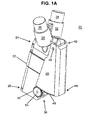
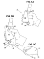
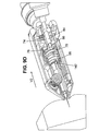
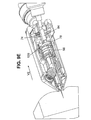
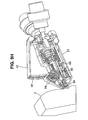
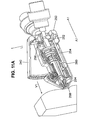
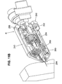
- an applicator device 20 for administering injections preferably includes a housing 22 having an upper end 24 and a lower end 26.
- the upper end 24 of the housing 22 preferably includes a first vial holder 28 adapted to receive a first vial 30 containing a first component, such as a first liquid component, and a second vial holder 32 adapted to receive a second vial 34 containing a second component, such as a second liquid component.
- the first and second vial holders 28, 32 may be adapted to receive replacement vials so that the first and second vials 30, 34 may be removed when empty and replaced with the replacement vials.
- the applicator device 20 preferably includes a drive system 36 for advancing an injection needle (not shown) from the lower end 26 of the housing 22 for insertion into tissue, drawing the first and second components from the first and second vials 30, 34, advancing the components downstream toward the injection needle, mixing the first and second components together, and dispensing the mixed components from the injection needle into tissue.
- the mixing of the two components occurs once the two components exit the first and second tubes (100, 106).
- the embodiment shown in FIG. 1A includes two vials containing two different components, in other embodiments the applicator device 20 may be adapted to receive three or more vials containing three or more components that are mixed together for formulating a mixed, injectable solution.
- the drive system 36 preferably includes an injection actuator, such as a handle 40, having an upper end 42 and a lower end 44.
- the upper end 42 of the handle 40 may be pivotally coupled with the upper end 24 of the housing 22 via a pivot connection 46.
- the handle may be pressed toward the housing 22 for activating the drive system 36.
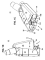
- the lower end 44 of the handle 40 desirably includes at least one set of gear teeth 48 that desirably engage gear teeth 52 on at least one external gear 54 that is rotatably mounted at the lower end 26 of the housing 22.
- the handle 40 desirably has a C-shaped cross-section that conforms to the outer surface of the housing 22.
- the handle 40 may be pressed toward the housing 22 in the direction indicated D 1 for activating the drive system 36 of the applicator device 20.
- the gear teeth 48 at the lower end 44 of the handle 40 preferably engage the gear teeth 52 on the external gear 54 for rotating the external gear 54 in a counterclockwise direction indicated R 1 .
- the drive system 36 of the applicator device 20 preferably includes a first external gear 54A rotatably mounted on a first side of the housing 22 and a second external gear 54B rotatably mounted on a second side of the housing 22.
- the handle 40 desirably includes a first set of gear teeth 48A at a lower end of the handle that are adapted to mesh with the gear teeth of the first external gear 54A and a second set of gear teeth 48B at a lower end of the handle adapted to mesh with the gear teeth on the second external gear 54B.
- the first and second external gears 54A, 54B rotate in a first direction as the handle is pressed toward the device housing 22, and a second, opposite direction as the handle returns to the original position shown in FIGS. 1A-1C .
- the drive system 36 desirably includes an internal gear 56 that is coupled with, and rotates simultaneously with, the first and second external gears 54A, 54B.
- the first and second external gears 54A, 54B and the internal gear 56 are desirably mounted on an elongated shaft 55 and rotate simultaneously with one another in response to rotation of the elongated shaft.
- the first and second sets of gear teeth 48A, 48B at the lower end of the handle 40 engage the teeth 52 on the respective first and second external gears 54A, 54B for rotating the external gears in a counterclockwise direction R 1 .
- the rotating first and second external gears 54A, 54B rotate the elongated shaft 55, which rotates the internal gear 56 in a counterclockwise direction.
- the lower end of the housing 22 preferably includes a bottom surface 58 having an injection needle opening 60 extending therethrough so that an injection needle (not shown) may be advanced through the injection needle opening.
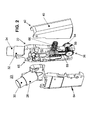
- the housing 22 of the applicator device 20 preferably has a main body 62 and a cover 64 that is adapted to be assembled with the main body 62.
- the main body and the cover preferably have internal surfaces that are adapted to receive and/or seat various parts of the drive system 36 and an injection system 65 for the applicator device.
- the drive system 36 and the injection system 65 are preferably disposed between the cover 64 and the main body 62 of the housing 22.
- an upper end 42 of the handle 40 may be pivotally connected to one or more external surfaces of the housing 22.
- the handle 40 may be pressed toward the housing 22 for commencing an injection cycle.
- the applicator device 20 preferably includes a handle spring 66 that extends between an inner surface of the handle 40 and an outer surface of the housing 22.
- the handle 40 may be released whereupon it is returned to the original position shown in FIGS. 1A-1C under the force of the handle spring 66.
- energy is stored in the handle spring 66.
- the handle 40 is released, the energy stored in the handle spring 66 is released for returning the handle 40 to the original position ( FIGS. 1A-1C ), which, in turn, retracts the injection needle.
- the applicator device includes an injection system 65 that operates in cooperation with the drive system 36.
- the injection system 65 preferably includes the first vial 30 containing a first liquid component, and the second vial 34 containing a second liquid component.
- the first vial 30 desirably has a lower end that is in fluid communication with a first one-way check valve 70, which enables the first liquid component to flow therethrough in only one direction.
- the first one-way check valve 70 is in fluid communication with a first T-connector 72.
- a lower end of the first T-connector 72 is preferably in fluid communication with a first syringe barrel 74 that desirably receives a first reciprocating plunger 76 having a lower end connected with a plunger base 78.
- the injection system 65 preferably includes the second vial 34-having a lower end in fluid communication with a second one-way check valve 80, which enables the second liquid component to flow therethrough in only one direction.
- the second one-way check valve 80 has a lower end in communication with a second T-connector 82, which is preferably in fluid communication with a second syringe barrel 84 that receives a second reciprocating plunger 86.
- each of the lower ends of the first and second reciprocating plungers 76, 86 are desirably connected with or project from the plunger base 78 for moving together with one another and with the plunger base.
- the first and second one-way check valves 70, 80 may include a needle assembly preferably adapted to puncture vial septums on the respective first and second vials 30, 34.
- one or more of the vial septums may be punctured by a needle protruding from the vial holder.
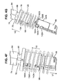
- the injection system preferably includes a needle housing 88 having an upper end 90 adapted for being repeatedly coupled and uncoupled from the plunger base 78 and a lower end 92 that carries an injection needle 94.
- An outer surface of the needle housing 88 desirably includes a rack 96 having a plurality of teeth that extend along the outer surface thereof.
- the teeth on the internal gear 56 preferably mesh with the rack 96 for selectively moving the needle housing 88 along an axis, such as a vertically extending axis.
- the injection system 65 preferably includes a plunger spring 98 that is compressible between the plunger base 78 and one or more internal surfaces of the device housing 22 ( FIG. 2 ) for selectively storing energy in the plunger spring.
- the injection system 65 desirably includes a first tube 100 that provides a first fluid path between the first syringe barrel 74 and the injection needle 94 so as to supply a first liquid component to the injection needle.
- the first tube 100 has an upper end in fluid communication with the first T-connector 72 and a lower end that passes through an opening 102 in the needle housing 88 for supplying the first liquid component to the injection needle 94.
- the first tube 100 preferably includes a one-way check valve 104 that enables the first liquid component to pass in only one direction, i.e., from the upper end to the lower end of the first tube 100.
- the injection system 65 desirably includes a second tube 106 that provides a second fluid path between the second syringe barrel 84 and the injection needle 94 so as to supply a second liquid component to the injection needle.
- the second tube 106 has an upper end in fluid communication with the second T-connector 82 and a lower end that passes through the needle housing opening 102 for supplying the second liquid component to the injection needle 94.
- the second tube 106 desirably includes a second one-way check valve 108 that enables the second liquid component from the second syringe barrel 84 to pass in only one direction, i.e., from the upper end toward the lower end of the second tube 106.
- the first and second sets of gear teeth 48A, 48B at the lower end 44 of the handle 40 rotate the first and second external gears 54A, 54B in a counterclockwise direction indicated R 1
- the first and second external gears 54A, 54B rotate in the counterclockwise direction, they, in turn, rotate the elongated shaft 55 which rotates the internal gear 56 in a counterclockwise direction.
- the teeth on the internal gear 56 desirably engage the rack 96 on the outer surface of the needle housing 88 for moving the needle housing and the injection needle 94 in a downward direction along an axis of the housing, such as a vertical axis.
- the needle housing pulls the plunger base 78 in the same downward direction.
- the first plunger 76 is retracted from the first syringe barrel 74, which draws the first liquid component from the first vial 30, through the first one-way check valve 70, through the first T-connector 72, and into the first syringe barrel 74.
- the second plunger 86 is retracted from the second syringe barrel 84, which draws the second liquid component from the second vial 34, through the second one-way check valve 80, through the second T-connector 82, and into the second syringe barrel 84.
- the plunger spring 98 is compressed between the plunger base 78 and one or more internal surfaces of the device housing 22. Energy is preferably stored in the plunger spring 98 as the plunger spring in compressed. As will be described in more detail below, at a certain stage of an injection cycle, the needle housing 88 decouples from the plunger base 78, which frees the plunger base to move in an upward direction via energy provided by the previously compressed plunger spring 98.
- the plunger base 78 advances the first and second plungers 76, 86 into the respective first and second syringe barrels 74, 84.
- the first plunger 76 forces the first liquid component from the first syringe barrel 74, through the first T-connector 72 and into the first tube 100 from which it flows downstream through an opening 102 in the needle housing 88.
- the first one-way check valve 70 preferably prevents the first liquid component from re-entering the first vial 30.
- the second plunger 86 forces the second liquid component from the second syringe barrel 84, through the second T-connector 82 and into the second tube 106 where it flows downstream through an opening 102 in the needle housing 88 for being mixed with the first liquid component and dispensed from the injection needle 94.
- the second one-way check valve 80 preferably prevents the second liquid component from re-entering the second vial 34.
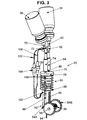
- the injection system 65 preferably includes the needle housing 88 having an upper end 112 and a lower end 114.
- the needle housing 88 desirably includes a main body 116 and a cover 118 that are assembled together.
- the outer surface of the main body 116 of the needle housing preferably includes the rack 96 that is adapted to mesh with the teeth on the internal gear 56 of the drive system 36 shown in FIG. 3 .
- the injection needle 94 is disposed within the main body 116 and extends from the lower end 114 of the needle housing 88.
- the injection needle is preferably connected to the main body 116 by a luer connection.
- the injection system 65 preferably includes the plunger spring 98 that overlies the upper end 112 of the needle housing 88.
- the plunger base 78 is preferably adapted to engage an upper end of the plunger spring 98.
- the plunger spring 98 is preferably compressed between the plunger base 78 and one or more internal surfaces of the housing 22 for storing energy in the plunger spring.
- energy stored in the plunger spring 98 is released for driving the plunger base 78 upward and away from the lower end of the device.
- the injection system 65 preferably includes the first and second plungers 76, 86 projecting from a top surface of the plunger base 78.
- the first and second plungers 76, 86 preferably move simultaneously with one another and with the plunger base.
- the injection system also preferably includes the first and second syringe barrels 74, 84 that are adapted to receive the respective first and second plungers 76, 86.
- the first and second plungers 76, 86 desirably reciprocate up and down within the syringe barrels 74, 84 for alternatively drawing the liquid components into and dispensing the liquid components from the syringe barrels.
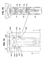
- the plunger base 78 preferably includes a disc 120 having a top surface 122 and a bottom surface 124, and a cylinder 126 projecting from the bottom surface 124 of the disc 120.
- the cylinder 126 preferably has an outer surface 128 and an inner surface 130 defining an elongated bore 132 extending between a lower end of the cylinder 126 and the bottom-surface 124 of the disc 120.
- the elongated bore 132 is adapted to receive an upper end 112 of the needle housing 88 as the needle housing and plunger base are coupled and decoupled from one another.
- the cylinder 126 preferably includes two upper slots 134A, 134B adjacent the bottom surface 124 of the disc 120, and two lower slots 136A, 136B that are open at the lower end of the cylinder 126.
- the two upper slots 134A, 134B are preferably aligned with one another on opposite sides of the cylinder 126.
- the two lower slots 136A, 136B are preferably aligned with one another on opposite sides of the cylinder 126.
- the needle housing 88 preferably includes at least one catch 140 that is adapted for sequentially coupling and decoupling the needle housing 88 and the plunger base 78.
- the needle housing preferably includes at least one catch actuator 142 that is coupled with the at least one catch 140 and is adapted for decoupling the needle housing 88 from the plunger base 78.
- the at least one catch 140 is preferably engaged with at least one of the two upper slots 134A, 134B, and the at least one catch actuator 142 is preferably aligned with one of the two lower slots 136A, 136B.
- the catch actuator 142 is pressed inwardly, such as by an interior surface of the housing 22, the catch 140 coupled therewith is urged inwardly for decoupling the needle housing 88 and the plunger base 78 from one another.
- FIG. 4D shows the needle housing 88 after the cover 118 has been disassembled from the main body 116.
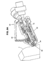
- the needle housing 88 preferably includes the injection needle 94 having an upper end connected with a needle hub 144.
- the needle hub 144 preferably has a reservoir opening 146 adapted to receive the distal ends of the first and second tubes 100, 106 ( FIG. 3 ) for receiving the first and second liquid components stored in the first and second vials.
- the needle hub 144 is desirably assembled with the main body 116 so that the injection needle 94 projects from the lower end of the needle housing 88. After the injection needle is assembled with the main body 116, the injection needle 94 preferably moves simultaneously with the main body 116 of the needle housing. Referring to FIG.
- the cover 118 of the needle housing 88 preferably includes a first elongated element 150 having a first inner surface 152, and an opposing second elongated element 154 having a second inner surface 156 that opposes the first inner surface.
- a first spring 158 preferably couples opposing upper ends of the opposing elongated elements 150, 154
- a second spring 160 preferably couples opposing lower ends of the first and second elongated elements 150, 154.
- the first and second springs 158, 160 normally urge the first and second elongated elements 150, 154 away from one another.
- the first elongated element 150 includes a first catch 140A connected therewith having a top sloping surface 162A and a bottom, horizontally extending surface 164A.
- the first elongated element 150 desirably includes a first catch actuator 142A connected thereto.
- the first catch actuator 142A is urged inwardly
- the first catch 140A connected therewith is also preferably urged inwardly.
- the second elongated element 154 preferably includes a second catch 140B having a top sloping surface 162B and a bottom, horizontally extending surface 164B.
- the second elongated element 154 preferably includes a second catch actuator 142B connected with the second elongated element 154.
- the second catch actuator 142B is urged inwardly
- the second catch 140B connected therewith is also preferably urged inwardly.
- the needle housing 88 is initially moved in a downward direction V 1 by the drive system 36 ( FIG. 3 )
- the catches 140 are seated in the upper slots 134 formed in the cylinder 126 of the plunger base 78.
- the needle housing pulls the plunger base 78 in the downward direction V 1 for compressing the plunger spring 98 and drawing the first and second liquid components into the syringe barrels 74, 84.
- the first and second catch actuators 142A, 142B are preferably pressed inwardly by one or more internal surfaces of the housing 22 for urging the first and second elongated elements 150, 154 ( FIG. 4E ) toward one another.
- the first and second springs 158, 160 extending between the elongated elements may be compressed for storing energy therein.
- the first and second catches 140A, 140B preferably move toward one another so that the first and second catches are decoupled from the two upper slots 134A, 134B formed in the cylinder 126 of the plunger base 78.
- the needle housing and the plunger base are decoupled so that the plunger spring 98, having energy stored therein drives the plunger base 78 in an upward vertical direction designated V 2 for advancing the first and second plungers 76, 86 into the respective first and second syringe barrels 74, 84 so as to dispense the first and second liquid components from the syringe barrels.
- the drive system 36 moves the needle housing 88 in an upward direction so that the first and second catches 140A, 140B may re-engage with the two upper slots 134A, 134B formed in the cylinder 126 of the plunger base 78 for re-coupling the needle housing with the plunger base 78.
- the sloping surfaces 162A, 162B on the respective first and second catches 140A, 140B preferably guide the catches into the upper slots 134A, 134B.
- the lower, horizontally extending surfaces 164A, 164B of the catches may maintain the connection between the needle housing 88 and the plunger base 78.
- the applicator device 20 may be held in an operator's hand with the device housing 22 opposing a palm of the operator's hand and the handle 40 being engaged by the operator's fingers.
- the external gear teeth 48 at the lower end of the handle 40 preferably engage the gear teeth on the external gear 54.
- the operator may press the handle 40 toward the device housing for commencing an injection cycle for the applicator device 20.
- the external gear teeth 48 at the lower end of the handle 40 and the external gear 54 cooperate for advancing an injection needle 94 from the bottom surface 58 of the housing 22.
- the first and second catch actuators 142A, 142B normally extend beyond the outer surface of the main body 116 of the needle housing 88.
- the first and second catch actuators 142A, 142B may be urged towards one another for, in turn, urging the first and second catches 140A, 140B toward one another.
- the respective first and second catches 140A, 140B connected therewith are retracted for decoupling the upper end 112 of the needle housing 88 from a plunger base 78.
- the horizontal surfaces 164A, 164B of the catches 140A, 140B engage the upper slots 134A, 134B formed in the cylinder 126 of the plunger base 78 for pulling the plunger base with the needle housing 88 in a downward direction.
- the plunger spring 98 is compressed, and the first and second plungers are retracted from the first and second syringe barrels for drawing the first and second liquid components into the respective first and second syringe barrels 74, 84.
- the first and second catch actuators 142A, 142B eventually come in contact with one or more internal surfaces 165 of the device housing 22 for moving the catch actuators 142A, 142B inwardly.
- the catches 140A, 140B coupled with the catch actuators are retracted until the horizontal surfaces 164A, 164B of the catches 140A, 140B decouple from the upper slots 134A, 134B of the plunger base 78, whereupon the plunger base is free to move in an opposite, upward direction V 2 under the force of the compressed plunger spring 98.
- the plunger base 78 After the plunger base 78 has been decoupled from the catches 140A, 140B of the needle housing 88, the plunger base 78 is free, under the energy of the plunger spring, to move in an upward direction V 2 . As the plunger base 78 moves in the upward direction, the first and second plungers 76, 86 are driven into the respective first and second syringe barrels 74, 84 for forcing the first and second liquid components present in the barrels 74, 84 downstream and into the respective first and second tubes 100, 106 ( FIG. 3 ).
- the injection system 65 preferably includes the needle housing 88 having an injection needle 94 projecting from a lower end thereof.
- the injection system includes the needle hub 144 coupled with an upper end of the injection needle 94.
- the needle hub 144 preferably includes a reservoir opening 146 at an upper end thereof that is adapted to receive the distal ends of the first and second tubes 100, 106.
- the needle hub 144 preferably includes a mixing chamber 175 that is in fluid communication with the distal ends of the first and second tubes 100, 106 so that the first and second liquid components delivered by the first and second tubes 100, 106 may be mixed together in the mixing chamber 175 before being dispensed from the distal end of the injection needle 94.
- the present invention is not limited by any particular theory of operation, it is believed that providing an applicator device that is able to mix together at least two different liquid components for injection from a single injection needle 94 provides many benefits over prior art devices.
- many prior art injection devices require medical personnel or an individual to use two different injection needles for introducing the two different liquid components into a patient's body.
- the use of two different injection needles may result in incomplete mixing of the first and second liquid components and misalignment of the first injection needle with the second injection needle at a target location. As a result, the two liquid components may not mix properly, which may have adverse consequences for a patient.
- the applicator device disclosed herein provides a number of benefits over prior art injection devices including a simple mechanical design that minimizes the number of parts by combining functions and features such as a needle housing 88 that contains the injection needle 94, functions as a drive system 36, and contains the catch 140.
- the injection needle is disposable and may be replaced by a replacement needle.
- the injection needle is disposable and includes a needle with a standard luer connection.
- the needle may be disposed of automatically such as by providing a pressable button on the device housing and pressing the button for ejection a first needle and replacing it with a second, replacement needle.
- FIGS. 9A-9I show a method of simultaneously injecting at least two liquid components into a patient using a single injection needle, in accordance with one embodiment of the present invention.
- the bottom surface 58 of the applicator device 20 is abutted against tissue T of a patient.
- the handle 40 Prior to commencement of a first stage of an injection cycle shown in FIG. 9A , the handle 40 is fully extended away from the device housing 22, the injection needle 94 is retracted inside the device housing 22, and the first and second plungers 76, 86 projecting from the plunger base 78 are fully advanced into the first and second syringe barrels 74, 84.
- an operator preferably squeezes the handle 40 toward the housing 22 to begin an injection sequence.
- the teeth 48 at the lower end of the handle 40 preferably rotate the first and second external gears 54, which, in turn, rotate the internal gear 56.
- the teeth of the internal gear 56 engage the rack 96 of the needle housing 88 for moving the needle housing in a direction V 1 toward the tissue T.
- the injection needle 94 at the lower end of the needle housing preferably advances into the tissue T.
- the needle housing 88 moves toward the bottom surface of the applicator device, the needle housing 88, which, at this stage of the injection cycle, is coupled with the plunger base 78, pulls the plunger base 78 toward the bottom surface 58 of the applicator device 20.
- the plunger spring 98 is compressed by the plunger base for storing energy in the plunger spring.
- the first and second plungers 76, 86 are withdrawn from the respective first and second syringe barrels 74, 84 for drawing the first and second liquid components from the respective first and second vials 30, 34 for filling the syringe barrels.
- the plunger spring 98 remains between the bottom surface of the plunger base 78 and one or more inner surfaces of the device housing as the plunger spring is compressed. As such, the length of the plunger spring 98 is shortened when being compressed, and then returns to its original length as it uncompresses.
- the handle 40 is fully squeezed against the housing 22 for further advancing the needle housing 88 toward the bottom surface 58 of the applicator device 20.
- the injection needle 94 is preferably fully advanced from the bottom surface 58 of the device for insertion into the tissue T.
- the first and second catches 140A, 140B remain coupled with the plunger base 78 so that the needle housing may continue to pull the plunger base toward the bottom surface 58 of the device housing 22.
- the plunger spring 98 continues to be compressed between the disc of the plunger base 78 and the inner surfaces of the device housing 22 for storing energy in the plunger spring.
- the first and second catch actuators 142A, 142B ( FIG. 7A ) are urged inwardly by the inner surfaces of the housing 22, which, in turn, urges the catches 140A, 140B inwardly for decoupling the needle housing 88 from the plunger base 78.
- the force stored in the plunger spring 98 is transmitted to the plunger base 78 for urging the plunger base 78 to move in an upward direction V 2 .
- the plunger base 78 urges the first and second plungers 76, 86 into the first and second syringe barrels 74, 84 for dispensing the first and second components into the first and second tubes 100, 106 ( FIG. 3 ) for advancing the first and second components downstream through the first and second tubes.
- the plunger base 78 is urged in an upward direction V 2 by the plunger spring 98 until the top surface 122 of the disc 120 of the plunger base 78 is preferably seated against lower ends of the first and second syringe barrels 74, 84.
- the first and second components previously drawn into the syringe barrels 74, 84 are evacuated from the syringe barrels and forced into the first and second tubes 100, 106 ( FIG. 3 ). Referring to FIG.
- the injection needle 94 remains fully inserted in the tissue T so that the mixed solution of the first and second liquid components may be injected into the tissue T.
- the injection device is adapted to dispense the solution from the needle only when the needle is fully extended.
- the needle is extracted from the tissue only when the handle is released by the administrator.
- the handle 40 may be released for enabling the handle to return to the original start position shown in FIG. 9A .
- the handle spring 66 FIG. 2
- the gear teeth 48 at the lower end 44 of the handle 40 preferably rotate the external gears 54 in an opposite direction, which, in turn, rotate the internal gear 56, which, in turn, drives the needle housing 88 in the upward direction V 2 .
- the injection needle 94 is withdrawn from the tissue T.
- FIG. 9H shows the handle 40 during a further stage of the injection cycle with the injection needle 94 fully withdrawn from the tissue T.
- FIG. 9I shows the applicator device 20 after the handle 40 has returned to the original position shown in FIG. 9A .
- the plunger spring 98 has preferably returned the plunger base 78 to the original start position ( FIG. 9A ) so that it seats against the lower ends of the of the respective syringe barrels 74, 84.
- the plunger spring 98 is preferably uncompressed and extends between a lower end of the plunger base 78 and one or more inner surfaces of the device housing 22.
- the catches 140 at the upper end of the needle housing 88 are desirably coupled with the slots 134 in the cylinder 126 of the plunger base 78 for once again coupling the needle housing 88 with the plunger base 78 so that the needle housing and plunger base are ready for another injection cycle.
- the needle housing preferably travels about 18 mm downwardly so that the injection needle may penetrate into tissue.
- the plunger stroke is approximately 12 mm.
- the required dose of each of the liquid components is about 200-500 micro-liters.
- a one milliliter syringe having a diameter of approximately 4.5-15 millimeters may be cut to a length of 10-30 millimeters and installed in the applicator device.
- the two upper slots 134A, 134B formed in the cylinder 126 below the disc 120 of the plunger base 78 may have lengths that are predetermined to provide for lost motion between the needle housing 88 and the plunger base.
- the one or more catches at the upper end of the needle housing initially slide in the upper slots 134A, 134B as the needle housing moves toward the bottom surface of the device housing. Ultimately, the one or more catches engage the lower, closed ends of the two slots 134A, 134B on the plunger base for beginning to pull the plunger base 78 toward the bottom surface of the housing so as to store energy in the plunger spring 98.
- the distance travelled downwardly by the needle housing before the one or more catches engage the slots of the plunger base is considered to be “lost motion” and this length may be changed depending upon the volume of the doses of the first and second components that are desired to be drawn into the first and second syringe barrels.
- the "lost motion" length may be increased for drawing less fluid into the syringe barrels. In one embodiment, the "lost motion" length may be decreased for drawing more fluid into the syringe barrels.
- the applicator device may be used for administering multiple and sequential injections of an at least two-component substance (e.g. Evicel).
- the applicator device preferably enables multiple injections of a fixed-dose of the mixed solution on a 2-D surface of a tissue while moving the device.
- the injection needle is automatically retracted from the patient's skin after the injection is completed without the need for the administrator to lift the device upward from the injection surface.
- the automatic needle extraction is controlled by the administrator.
- the device may be used for the administration of fibrin sealant with a fibrinogen component and a thrombin component.
- the device may be used for the administration of fibrin with cells for induction of revascularization along a severely ischemic limb, e.g. in diabetic patients.
- the device is used for the administration of a cell suspension.
- the cells are formulated with the fibrinogen component, the thrombin component and/or is administered as a separated component.
- the administered cells can be isolated from mammalian tissues.
- the device is used for the administration of a viscous component.
- an applicator device 220 may include an automatic needle ejection system adapted for disposing an injection needle 294 by engaging an actuator such as an injection needle release button 250.
- the needle ejection system preferably has a locked state in which it is impossible to eject an injection needle and an unlocked state in which it is possible to eject an injection needle.
- the needle ejection system preferably uses structure similar to that found in pipette tip ejection systems.
- the injection needle 294 is coupled with the needle housing 288 via a luer connection.
- the needle ejection system preferably includes a safety lever fork 252 that extends between a handle 240 and a needle ejection rod 254.
- the ejection rod 254 is preferably coupled with the release button 250.
- the needle ejection system desirably includes a safety lever spring 256 coupled with the safety lever fork 252.
- the safety lever fork 252 is retracted so that the injection needle release button 250 is unlocked and free to move up and down along an axis A 1 .
- a surface of the handle 240 desirably engages the safety lever fork 252 for urging the safety lever fork in the direction R so that the safety lever fork 252 engages the injection needle release button 250 for locking the injection needle release button in place, and preventing the release button from being pressed downward along the axis A 1 .
- the safety lever spring 256 is compressed for storing energy therein. In one embodiment, as long as the safety lever fork 252 remains in contact with the injection needle release button 250 ( FIG.
- the release button 250 may not be pressed for actuating the needle ejection system for ejecting an injection needle 294.
- the safety lever spring 256 preferably urges the safety lever fork 252 in the direction L for decoupling the safety lever fork 252 from the injection needle release button 250.
- the release button 250 and the rod 254 are free to move along the axis A 1 .
- the needle ejection system preferably includes a fork lever 260 that is coupled with a lower end of the ejection rod 254 for moving simultaneously with the ejection rod along the axis A 1 .
- the fork lever 260 preferably has a first end 262 and a second end 264.
- the first end 262 is preferably coupled with a needle hub load spring 266 and the second end 264 is preferably coupled with a fork lever spring 268.
- the ejection rod 254 may be moved in a downward direction V 1 for, in turn, moving the fork lever 260 in the direction V 1 .
- the needle hub load spring 266 and the fork lever spring 268 are compressed and the needle is ejected.
- the needle hub load spring 266 and the fork lever spring 268 urge the fork lever 260 upward for, in turn, urging the ejection rod 254 upward.
- the needle ejection system is preferably unlocked when the handle 240 is in the position shown in FIG. 11A and locked when the handle 240 is in the position shown in FIG. 11B .
- the handle 240 desirably urges the safety lever fork 252 in the direction R.
- the safety lever fork 252 is seated against the needle release button 250, which prevents both actuation of the release button 250 and movement of the ejection rod 254 in the direction V 1 .
- the safety lever fork 252 is in the extended position shown in FIG.
- the safety lever fork 252 creates a physical barrier that blocks movement of the release button 250 in the direction V 1 so that actuation of the needle ejection system is impossible.
- the safety lever spring 256 is compressed. After an injection has been made, release of the handle -240 results in movement of the safety lever fork 252 in an opposite direction L under the force of the safety lever spring 256 ( FIG. 11A ).
Priority Applications (12)
| Application Number | Priority Date | Filing Date | Title |
|---|---|---|---|
| EP10250976A EP2389969A1 (de) | 2010-05-26 | 2010-05-26 | Vorrichtung zum Injizieren einer Substanz |
| CA2794185A CA2794185C (en) | 2010-03-24 | 2011-03-22 | Devices for injecting a substance and methods therefor |
| JP2013500655A JP5819396B2 (ja) | 2010-03-24 | 2011-03-22 | 物質を注射するためのデバイス |
| ES11716310.5T ES2557406T3 (es) | 2010-03-24 | 2011-03-22 | Dispositivos para inyectar una sustancia y métodos para ello |
| PCT/IL2011/000268 WO2011117867A2 (en) | 2010-03-24 | 2011-03-22 | Devices for injecting a substance and methods therefor |
| AU2011231109A AU2011231109B2 (en) | 2010-03-24 | 2011-03-22 | Devices for injecting a substance and methods therefor |
| US13/053,448 US9278181B2 (en) | 2010-03-24 | 2011-03-22 | Devices for injecting a substance and methods therefor |
| EP11716310.5A EP2550048B1 (de) | 2010-03-24 | 2011-03-22 | Vorrichtungen zur injektion eines substanz und verfahren dafür |
| IL222009A IL222009B (en) | 2010-03-24 | 2012-09-20 | Devices for injecting a substance |
| JP2015077523A JP6087385B2 (ja) | 2010-03-24 | 2015-04-06 | 物質を注射するためのデバイス |
| US15/007,346 US10118002B2 (en) | 2010-03-24 | 2016-01-27 | Devices for injecting a substance and methods therefor |
| JP2016133144A JP6377677B2 (ja) | 2010-03-24 | 2016-07-05 | 物質を注射するためのデバイス |
Applications Claiming Priority (1)
| Application Number | Priority Date | Filing Date | Title |
|---|---|---|---|
| EP10250976A EP2389969A1 (de) | 2010-05-26 | 2010-05-26 | Vorrichtung zum Injizieren einer Substanz |
Publications (1)
| Publication Number | Publication Date |
|---|---|
| EP2389969A1 true EP2389969A1 (de) | 2011-11-30 |
Family
ID=42989654
Family Applications (2)
| Application Number | Title | Priority Date | Filing Date |
|---|---|---|---|
| EP10250976A Withdrawn EP2389969A1 (de) | 2010-03-24 | 2010-05-26 | Vorrichtung zum Injizieren einer Substanz |
| EP11716310.5A Active EP2550048B1 (de) | 2010-03-24 | 2011-03-22 | Vorrichtungen zur injektion eines substanz und verfahren dafür |
Family Applications After (1)
| Application Number | Title | Priority Date | Filing Date |
|---|---|---|---|
| EP11716310.5A Active EP2550048B1 (de) | 2010-03-24 | 2011-03-22 | Vorrichtungen zur injektion eines substanz und verfahren dafür |
Country Status (8)
| Country | Link |
|---|---|
| US (2) | US9278181B2 (de) |
| EP (2) | EP2389969A1 (de) |
| JP (3) | JP5819396B2 (de) |
| AU (1) | AU2011231109B2 (de) |
| CA (1) | CA2794185C (de) |
| ES (1) | ES2557406T3 (de) |
| IL (1) | IL222009B (de) |
| WO (1) | WO2011117867A2 (de) |
Cited By (1)
| Publication number | Priority date | Publication date | Assignee | Title |
|---|---|---|---|---|
| US9468586B2 (en) | 2011-10-31 | 2016-10-18 | Ge Healthcare Limited | Pierce and fill device |
Families Citing this family (17)
| Publication number | Priority date | Publication date | Assignee | Title |
|---|---|---|---|---|
| US7909789B2 (en) | 2006-06-26 | 2011-03-22 | Sight Sciences, Inc. | Intraocular implants and methods and kits therefor |
| US9022987B2 (en) | 2008-07-07 | 2015-05-05 | Gabriel Institute, Inc. | Delivery system for injection through zone of body |
| US9808578B2 (en) | 2008-07-07 | 2017-11-07 | Gabriel Institute, Inc. | Delivery system for injections throughout zone of body |
| US8529516B2 (en) | 2008-07-07 | 2013-09-10 | Gabriel Institute, Inc. | Syringe for injection through zone of body |
| WO2011097408A1 (en) | 2010-02-05 | 2011-08-11 | Sight Sciences, Inc | Intraocular implants and related kits and methods |
| EP2389969A1 (de) * | 2010-05-26 | 2011-11-30 | Omrix Biopharmaceuticals Ltd. | Vorrichtung zum Injizieren einer Substanz |
| WO2013141898A1 (en) | 2012-03-20 | 2013-09-26 | Sight Sciences, Inc. | Ocular delivery systems and methods |
| DK3682920T3 (da) | 2013-06-18 | 2022-10-03 | Enable Injections Inc | Indretning og fremgangsmåde til hætteglasoverførsel og injektion |
| EP2832390A1 (de) * | 2013-07-30 | 2015-02-04 | Sensile Pat AG | Arzneimittelabgabevorrichtung mit Nadelbetätigungsmechanismus |
| US9387151B2 (en) | 2013-08-20 | 2016-07-12 | Anutra Medical, Inc. | Syringe fill system and method |
| ES2712898T3 (es) * | 2014-01-30 | 2019-05-16 | Medical Injection Devices Inc | Dispositivo dispensador de medicamentos |
| USD763433S1 (en) * | 2014-06-06 | 2016-08-09 | Anutra Medical, Inc. | Delivery system cassette |
| USD774182S1 (en) | 2014-06-06 | 2016-12-13 | Anutra Medical, Inc. | Anesthetic delivery device |
| US10299958B2 (en) | 2015-03-31 | 2019-05-28 | Sight Sciences, Inc. | Ocular delivery systems and methods |
| US11517527B2 (en) | 2018-11-05 | 2022-12-06 | Ethicon, Inc. | Systems, devices and methods for making and expressing foam used in medical procedures |
| EP4028081A1 (de) * | 2019-09-11 | 2022-07-20 | Eli Lilly and Company | Medikamentenabgabevorrichtung mit nadelträger |
| US11504270B1 (en) | 2019-09-27 | 2022-11-22 | Sight Sciences, Inc. | Ocular delivery systems and methods |
Citations (7)
| Publication number | Priority date | Publication date | Assignee | Title |
|---|---|---|---|---|
| US4026288A (en) * | 1975-10-21 | 1977-05-31 | Insulin Injector Inc. | Syringe injecting device |
| US4359049A (en) | 1980-04-02 | 1982-11-16 | Immuno Aktiengesellschaft Fur Chemisch-Medizinische Produkte | Apparatus for applying a tissue adhesive on the basis of human or animal proteins |
| US4609371A (en) | 1985-06-24 | 1986-09-02 | Pizzino Joanne L | Dual syringe for either simultaneous or sequential injection of liquids |
| WO2000069488A2 (en) * | 1999-05-12 | 2000-11-23 | Pharmacia Ab | Self-injection device and method for its operation |
| US20040069044A1 (en) * | 1999-04-29 | 2004-04-15 | Gilad Lavi | Device for measuring a volume of drug |
| WO2006020256A2 (en) * | 2004-07-19 | 2006-02-23 | Paragon Intellectual Properties, Llc | Systems and methods for atraumatic implantation of bio-active agents |
| EP1845860A1 (de) | 2005-11-22 | 2007-10-24 | Omrix Biopharmaceuticals S.A. | Applikatorvorrichtung zum aufbringen einer mehrkomponenten-flüssigkeit |
Family Cites Families (21)
| Publication number | Priority date | Publication date | Assignee | Title |
|---|---|---|---|---|
| US3572336A (en) | 1968-04-30 | 1971-03-23 | Daniel R Hershberg | Syringe |
| US4028288A (en) | 1976-02-03 | 1977-06-07 | Tire Recyclers International, Inc. | Moldable end products from primarily reclaimable waste materials |
| DE3417757C2 (de) * | 1984-05-12 | 1994-11-10 | Lucas Dieter Dr | Injektionsspritze |
| WO1991007197A1 (de) * | 1989-11-21 | 1991-05-30 | Andreas Lindner | Injektionsvorrichtung |
| US5298023A (en) * | 1991-03-08 | 1994-03-29 | Habley Medical Technology Corporation | Multiple pharmaceutical dispenser with accumulator |
| US5749968A (en) * | 1993-03-01 | 1998-05-12 | Focal, Inc. | Device for priming for improved adherence of gels to substrates |
| US5478323A (en) | 1993-04-02 | 1995-12-26 | Eli Lilly And Company | Manifold for injection apparatus |
| JPH0767961A (ja) | 1993-07-09 | 1995-03-14 | Terumo Corp | 注射器 |
| US6783514B2 (en) * | 1997-01-31 | 2004-08-31 | United States Surgical Corporation | Fibrin sealant applicator |
| WO1999032173A1 (en) * | 1997-12-19 | 1999-07-01 | United States Surgical Corporation | Two component dispenser system |
| JP2004065737A (ja) | 2002-08-08 | 2004-03-04 | Nemoto Kyorindo:Kk | 薬液注入装置 |
| US20040064102A1 (en) * | 2002-09-30 | 2004-04-01 | Akira Yamada | Double-barrel syringe for ophthalmic surgeries |
| US7641668B2 (en) * | 2003-05-16 | 2010-01-05 | Scimed Life Systems, Inc. | Fluid delivery system and related methods of use |
| PL2058020T3 (pl) | 2005-02-01 | 2013-03-29 | Kaleo Inc | Urządzenie do podawania leków |
| US20080167621A1 (en) | 2005-05-16 | 2008-07-10 | Wagner Gary S | Multi-Barrel Syringe Having Integral Manifold |
| EP1942978B1 (de) * | 2005-09-14 | 2019-07-17 | ACIST Medical Systems, Inc. | Injektionssystem für medizinische flüssigkeiten |
| EP2214757A1 (de) * | 2007-11-22 | 2010-08-11 | Novo Nordisk Health Care AG | Medizinisches mischgerät |
| WO2009086182A1 (en) * | 2007-12-21 | 2009-07-09 | Carticept Medical, Inc. | Articular injection system |
| EP2389969A1 (de) * | 2010-05-26 | 2011-11-30 | Omrix Biopharmaceuticals Ltd. | Vorrichtung zum Injizieren einer Substanz |
| US8568446B2 (en) * | 2010-05-13 | 2013-10-29 | Ethicon Endo-Surgery, Inc. | Multi-chamber therapeutic cell applicator instrument |
| US8491526B2 (en) * | 2010-05-13 | 2013-07-23 | Ethicon Endo-Surgery, Inc. | Therapeutic cell applicator instrument with modular tips |
-
2010
- 2010-05-26 EP EP10250976A patent/EP2389969A1/de not_active Withdrawn
-
2011
- 2011-03-22 CA CA2794185A patent/CA2794185C/en not_active Expired - Fee Related
- 2011-03-22 US US13/053,448 patent/US9278181B2/en not_active Expired - Fee Related
- 2011-03-22 AU AU2011231109A patent/AU2011231109B2/en not_active Ceased
- 2011-03-22 WO PCT/IL2011/000268 patent/WO2011117867A2/en active Application Filing
- 2011-03-22 ES ES11716310.5T patent/ES2557406T3/es active Active
- 2011-03-22 JP JP2013500655A patent/JP5819396B2/ja not_active Expired - Fee Related
- 2011-03-22 EP EP11716310.5A patent/EP2550048B1/de active Active
-
2012
- 2012-09-20 IL IL222009A patent/IL222009B/en not_active IP Right Cessation
-
2015
- 2015-04-06 JP JP2015077523A patent/JP6087385B2/ja not_active Expired - Fee Related
-
2016
- 2016-01-27 US US15/007,346 patent/US10118002B2/en active Active
- 2016-07-05 JP JP2016133144A patent/JP6377677B2/ja not_active Expired - Fee Related
Patent Citations (7)
| Publication number | Priority date | Publication date | Assignee | Title |
|---|---|---|---|---|
| US4026288A (en) * | 1975-10-21 | 1977-05-31 | Insulin Injector Inc. | Syringe injecting device |
| US4359049A (en) | 1980-04-02 | 1982-11-16 | Immuno Aktiengesellschaft Fur Chemisch-Medizinische Produkte | Apparatus for applying a tissue adhesive on the basis of human or animal proteins |
| US4609371A (en) | 1985-06-24 | 1986-09-02 | Pizzino Joanne L | Dual syringe for either simultaneous or sequential injection of liquids |
| US20040069044A1 (en) * | 1999-04-29 | 2004-04-15 | Gilad Lavi | Device for measuring a volume of drug |
| WO2000069488A2 (en) * | 1999-05-12 | 2000-11-23 | Pharmacia Ab | Self-injection device and method for its operation |
| WO2006020256A2 (en) * | 2004-07-19 | 2006-02-23 | Paragon Intellectual Properties, Llc | Systems and methods for atraumatic implantation of bio-active agents |
| EP1845860A1 (de) | 2005-11-22 | 2007-10-24 | Omrix Biopharmaceuticals S.A. | Applikatorvorrichtung zum aufbringen einer mehrkomponenten-flüssigkeit |
Cited By (1)
| Publication number | Priority date | Publication date | Assignee | Title |
|---|---|---|---|---|
| US9468586B2 (en) | 2011-10-31 | 2016-10-18 | Ge Healthcare Limited | Pierce and fill device |
Also Published As
| Publication number | Publication date |
|---|---|
| EP2550048B1 (de) | 2015-09-23 |
| JP2013521972A (ja) | 2013-06-13 |
| JP6377677B2 (ja) | 2018-08-22 |
| US10118002B2 (en) | 2018-11-06 |
| JP5819396B2 (ja) | 2015-11-24 |
| ES2557406T3 (es) | 2016-01-25 |
| JP2015163202A (ja) | 2015-09-10 |
| CA2794185A1 (en) | 2011-09-29 |
| EP2550048A2 (de) | 2013-01-30 |
| JP6087385B2 (ja) | 2017-03-01 |
| WO2011117867A2 (en) | 2011-09-29 |
| US20160136360A1 (en) | 2016-05-19 |
| IL222009B (en) | 2018-04-30 |
| US20110238009A1 (en) | 2011-09-29 |
| US9278181B2 (en) | 2016-03-08 |
| JP2016190068A (ja) | 2016-11-10 |
| AU2011231109A1 (en) | 2012-10-25 |
| AU2011231109B2 (en) | 2016-02-25 |
| WO2011117867A3 (en) | 2011-11-17 |
| CA2794185C (en) | 2019-05-07 |
Similar Documents
| Publication | Publication Date | Title |
|---|---|---|
| US10118002B2 (en) | Devices for injecting a substance and methods therefor | |
| US6599272B1 (en) | Injection device and method for its operation | |
| EP2195052B1 (de) | Externe arzneimittelpumpe | |
| KR100843007B1 (ko) | 주사기 기구 및 유닛과, 액체 방출 방법 | |
| AU675534B2 (en) | Multiple medication injection apparatus and method | |
| AU2009224052B2 (en) | Veterinary syringe for multiple injections | |
| US8640921B2 (en) | Device, system and method for dispensing a fixed dose of fluid | |
| US20020007142A1 (en) | Medical arrangement | |
| JP2009508602A (ja) | 2チャンバアンプルの自動注射装置 | |
| EA019609B1 (ru) | Автоинжектор с возможностью наполнения | |
| EP3468642B1 (de) | Dosiergerät und injektionsvorrichtung | |
| KR102492571B1 (ko) | 적어도 하나의 물질을 분배하기 위한 장치 및 방법 | |
| CN205460432U (zh) | 用药笔 | |
| JP2020517393A (ja) | 自動流体注入装置 | |
| GB2462303A (en) | Auto injector with filling mechanism | |
| EA044677B1 (ru) | Устройство для введения, предназначенное для интравитреального введения жидкости | |
| CZ2009714A3 (cs) | Dvouampulové inzulínové pero/aplikátor | |
| CN114096292A (zh) | 用于施用流体的施用装置 | |
| EP3806931A1 (de) | Medikamentenabgabevorrichtung und medikamentenabgabeanordnung |
Legal Events
| Date | Code | Title | Description |
|---|---|---|---|
| AK | Designated contracting states |
Kind code of ref document: A1 Designated state(s): AL AT BE BG CH CY CZ DE DK EE ES FI FR GB GR HR HU IE IS IT LI LT LU LV MC MK MT NL NO PL PT RO SE SI SK SM TR |
|
| AX | Request for extension of the european patent |
Extension state: BA ME RS |
|
| PUAI | Public reference made under article 153(3) epc to a published international application that has entered the european phase |
Free format text: ORIGINAL CODE: 0009012 |
|
| STAA | Information on the status of an ep patent application or granted ep patent |
Free format text: STATUS: THE APPLICATION IS DEEMED TO BE WITHDRAWN |
|
| 18D | Application deemed to be withdrawn |
Effective date: 20120531 |