EP2389891A2 - Implant analogique - Google Patents
Implant analogique Download PDFInfo
- Publication number
- EP2389891A2 EP2389891A2 EP11167401A EP11167401A EP2389891A2 EP 2389891 A2 EP2389891 A2 EP 2389891A2 EP 11167401 A EP11167401 A EP 11167401A EP 11167401 A EP11167401 A EP 11167401A EP 2389891 A2 EP2389891 A2 EP 2389891A2
- Authority
- EP
- European Patent Office
- Prior art keywords
- dental model
- implant
- analog
- proximal portion
- dental
- Prior art date
- Legal status (The legal status is an assumption and is not a legal conclusion. Google has not performed a legal analysis and makes no representation as to the accuracy of the status listed.)
- Pending
Links
Images


Classifications
-
- A—HUMAN NECESSITIES
- A61—MEDICAL OR VETERINARY SCIENCE; HYGIENE
- A61C—DENTISTRY; APPARATUS OR METHODS FOR ORAL OR DENTAL HYGIENE
- A61C8/00—Means to be fixed to the jaw-bone for consolidating natural teeth or for fixing dental prostheses thereon; Dental implants; Implanting tools
- A61C8/0001—Impression means for implants, e.g. impression coping
Definitions
- the present invention relates to an analog implant, in particular an analog implant, which can be used in a CAD / CAM manufactured dental model for the adaptation of a dental prosthesis.
- An analog implant for the adaptation of dental prostheses is known, which can be embedded in a plaster model.
- a dental implant screw implanted in a bone tissue is fabricated into a plaster model that represents the dental position of the patient's mouth with the implant screw.
- the analog implant is inserted into a suitably formed hole in the plaster model, whereupon the technician can adjust the dental prosthesis.
- That from the US 2003/0162 148 A1 known analog implant is disadvantageous in that it does not contain information that would allow the analog implant to be inserted into a CAD / CAM manufactured dental model.
- the problem in the art is that At present it is only possible to produce a dental model with an analog implant by molding the jaw of the patient with a corresponding impression compound and by embedding a impression post in the impression material.
- the impression post is indispensable for correctly positioning the analog implant in the dental model.
- an object of the present invention to provide an analog implant which overcomes the above disadvantages and which is particularly suitable for adapting a dental prosthesis to a CAD / CAM dental model outside the patient's mouth.
- distal refers to an area farther from the Dental model and the term “proximal” is an area that is closer to the dental model.
- distal is synonymous with “coronal” and “proximal” with “apical”.
- Scanbody 21 includes a proximal end that fits snugly into the distal end of the dental implant screw.
- the scanbody 21 comprises a distal end with a defined scannable surface, which is preferably polygonal and extends from the soft tissue to be detected by a scanner 20.
- the position and direction of the dental implant screw can be determined exactly from the scanned data of the position and direction of the distal part of the scanbody 21, in a manner which is known to the person skilled in the art and will not be explained further here.
- the scanner 20 is located in the mouth of the patient and is directed essentially to the scanbody 21, but can also scan the neighboring areas of the scanbody 21, so that the intact adjacent teeth 22 are also detected.
- the position and direction of the scanbody 21 is detected relative to the intact adjacent teeth 22 as a digital virtual impression of that portion of the mouth.
- Gypsum model of the restored dental area and its intact environment is produced.
- a digital dental model can thus be created, on the basis of which, at a later time, the CAM / CAD dental model 10 can be produced by means of milling, for example.
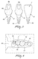
- FIG. 2 Figure 10 shows a screen shot of a CAD software for the design of a dental prosthesis 7.
- a virtual impression is displayed that is in accordance with the virtual impression data of the scanned area of the patient's mouth with the adjacent intact teeth 12 as impressions of the original adjacent ones intact teeth 22, with the soft tissue 11 and with a calculated bore or blind bore of the distal end of the dental implant screw, which is calculated on the basis of the known geometry of the scanbody 21.
- a prosthesis structure with an abutment 6 and a dental prosthesis 7 can be designed.
- the abutment 6 can either be selected from a number of finished abutments or manufactured as a customized piece (customized abutment).
- abutments 6 which are made of different materials (ceramic or titanium) and include a proximal end 6c, which is connectable to the distal end of the dental implant screw.
- a connecting screw which can be seen at the proximal end 6c of the abutment 6, can be inserted through a distal opening 6a at the distal end 6b of the abutment.
- Fig. 3 further shows on the right an abutment 6 connected to the dental prosthesis 7.
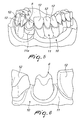
- FIG. 12 shows a portion of a CAM / CAD-fabricated dental model 10 fabricated from the virtual impression data, wherein the dental model 10 includes a plurality of impressions of intact teeth 12.
- the dental prosthesis 7 with a corresponding chewing surface 7a to see.
- Reference numeral 11 denotes the course of the soft tissue on the dental model 10.
- Fig. 5 shows the complete dental model 4, wherein the same reference numerals as in Fig. 4 be used.
- the soft tissue 11 is partially milled integrally with the dental model 10 (or made by equivalent methods).
- a part 11a of the soft tissue 11 can also be processed separately to facilitate its manufacture.
- the accuracy at a connection interface 5 of the analog implant 1 described below having an abutment can be increased.
- Fig. 6 11 shows an enlarged portion of the dental model 10 with the intact teeth 12, the soft tissue 11, and the abutment 6 placed on the analog implant (not shown), in which embodiment the soft tissue 11 of the dental model is integrally formed.
- Fig. 7 is a three-dimensional side view of the CAM / CAD procedures milled or otherwise processed dental model 10, a gate (in about the section of the Fig. 4 correspondingly) around the analogous implant 5 in a cross-sectional view.
- the dental model 10 is connected in the shown by means of a fastening device 13 with a milling cutter.
- the analog implant 1 of the invention has a certain asymmetric geometry, which its precise height, axial and angular orientation in the bore or Blind bore of the dental model allowed.
- the calculated on the basis of the known geometry of the scanbody 21 bore or blind bore exactly reflects the height, axial and angular orientation of the dental implant screw so that the analog implant 1 according to the invention also exactly follows the alignment of the dental implant screw and thus allows a precise adjustment of the dental prosthesis 7 on the dental model ,
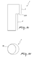
- the analog implant 1 preferably has, as in the FIGS. 8a and 8b shown, a substantially cylindrical distal portion 2 with the connection interface 5 to the abutment 6, which is substantially equal to the connection interface of a dental implant screw.
- the analog implant 1 may be provided at its connection interface 5 with a depression or blind bore 5a and a surface 5b to facilitate placement of the abutment 6.
- a circumferential incision 3 can be provided as a further positioner aid and / or for a better connection to the abutment 6.
- a proximal ledge 222 of the distal portion 2 provides a height stop that allows accurate positioning of the analog implant 1 in height on the dental model 10 and soft tissue 11 of the dental model 10, respectively.
- the proximal section 4 of the analog implant 1 is not round symmetrical and designed to secure the analog implant 1 in the bore of the dental model 10 in a certain angular position. Furthermore, a threaded hole 4d for securing to the dental model can be provided on the analog implant 1.
- the proximal portion 4 is formed with at least two flattened regions 4a obtained by ablation of respective parts of a cylinder and rotationally symmetrical about the axis of the proximal non-circularly symmetric portion 4, whereby the axial securing of the analogous implant 1 and its repositioning in a correspondingly formed bore or blind bore of the dental model 10 is possible. Due to the geometry of the analog implant 1 of the embodiment of the Fig.
- the proximal portion 4 is formed with an elliptical cross-section 4b.
- the distal portion 2 corresponds to that of the embodiment of FIG Fig. 8a and 8b and is therefore not explained in detail.
- the embodiment of the Fig. 8c and 8d offers the same advantages as the one of Fig. 8a and 8b because its geometry also allows for removal and axial adjustment of the length of analog implant 1.
- the analog implant 1 of the embodiment is the Fig. 8c and 8d (like that of the FIGS. 8a and 8b ) in two positions in the bore or blind bore of the dental model 10 by a dental technician repositionable, wherein also in the case of the embodiment of Fig. 8c and 8d the bore or blind bore of the dental model 10 has a shape that is complementary to the elliptical shape of the portion 4.
- the external geometry of the proximal portion 4 is also in this embodiment such that the analog implant 1 is removable from the dental model 10.
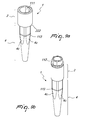
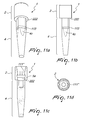
- Fig. 9a shows a further embodiment of an analog implant 1 having a first distal portion 2 and a second proximal portion 4.
- the first distal portion 2 is preferably circularly symmetrical and includes, as usual, in the perspective view only partially visible blind bore or opening, with a suitable connection profile 111 for rotationally secure receiving a (not shown) body part or abutment can be equipped.
- the second proximal portion 4 is provided with a first, preferably cylindrical distal part and a second, preferably conical, proximal part. However, it is conceivable according to the invention to form the second proximal section 4 in its entirety cylindrical or conical.
- the second proximal portion 4 is formed with a plurality of flattened areas or incisions 4c, which is its rotationally secure positioning and repositioning in a in the Fig. 9a not shown dental model and are arranged rotationally symmetrical about the axis of the second proximal portion 4.
- the number of flattened portions or recesses 4c is four and their arrangement about the axis of the second portion 4 is rotationally symmetric.
- the number of flattened regions or cuts 4c may also assume other numerical values greater than two, while maintaining the rotational symmetry.
- the proximally located paragraph 222 of first distal portion 2 of the analog implant 1 provides a height stop that allows accurate positioning of the analog implant 1 in height on the dental model 10 and soft tissue 11 of the dental model 10, respectively.
- the embodiment of the Fig. 9a offers the same advantages as the one of Fig. 8c and 8d because its geometry also allows for removal, repositioning and axial adjustment of the length of analog implant 1.
- the repositionability is adjusted with the number of flattened areas or cuts 4c.
- the shape of the bore or the blind bore of the dental model 10 of the increased number of flattened rotationally symmetrical regions 4a adapt.
- the external geometry of the proximal portion 4 is also in this embodiment such that the analog implant 1 is removable from the dental model 10.
- the Fig. 9a shows an exemplary embodiment of the connection profile 111, which is formed as in the interior of the blind bore in the cylindrical distal portion 2 of the analog implant.
- the connection profile 111 is octagonal, wherein the octagon in addition to the illustrated shape of Fig. 9a also accept the synOcta® connection of the owner of the current application (see FIGS. 10a to 10d ).
- the external geometry of the analog implant 1 with the flattened areas or recesses 4c is with the Connection profile compatible.
- the relationship of the connection profile 111 with the flattened areas or incisions 4c is predetermined.
- the cylindrical distal portion 2 may have various dimensions such as Narrow Neck, RN (Regular Neck), WN (Wide Neck), RC (Regular CrossFit TM), NC (Narrow CrossFit TM ”) and the like, which are manufactured and sold by the assignee of the present application.
- connection profile 112 is formed as a polygon above the cylindrical distal portion 2.
- the polygon is formed as an octagon.
- this modification differs from the embodiment of FIG Fig. 9a basically not.
- connection profile 111 ' is designed as a synOcta® connection in the cylindrical distal section 2 of the analog implant 1.
- blind bore 5a of the analog implant 1 in the sectional view of Fig. 10c in full length the blind bore 5a of the analog implant 1 in the sectional view of Fig. 10c in full length.
- this second modification differs from the embodiment of FIG Fig. 9a basically not and therefore the individual component of this modification will not be further explained.
- connection profile 111 is designed as the CrossFit TM connection of the present application owner with self-supporting internal prosthetic connection elements in the cylindrical distal section 2 of the analog implant 1.
- this third modification differs from the embodiment of FIG Fig. 9a basically not and therefore the individual component of this modification will not be further explained.
- All described embodiments of the analog implant 1 according to the invention advantageously comprise a marking on the proximal non-circularly symmetric section 4, which indicates to the dental technician, up to which point, the analog implant 1 can be shortened without losing its functionality.
- the marker shows the maximum shortenable length of the analog implant 1, without damaging its inner blind bore and / or affecting its rotation lock on the dental model 10.
- the analog implant 1 can be adapted according to the dimensions of the dental model 10 in its length and its functionality is not affected.
- This mark is in the FIGS. 9a, 9b . 10a, 10b . 11a and 11b designated by the reference numeral 113 and may advantageously consist of a laser mark.
- the precise positionability of the analog implant of the invention and the possibility of its repositioning is particularly advantageous when the analog implant is used in a dental model made by CAM / CAD, the dental model being made from a digital virtual impression of the mouth or part of the mouth.
- the adaptability of the length of the analog implant according to the invention allows its optimal integration in a dental model.
Applications Claiming Priority (1)
| Application Number | Priority Date | Filing Date | Title |
|---|---|---|---|
| DE102010021601A DE102010021601A1 (de) | 2010-05-26 | 2010-05-26 | Analogimplantat |
Publications (2)
| Publication Number | Publication Date |
|---|---|
| EP2389891A2 true EP2389891A2 (fr) | 2011-11-30 |
| EP2389891A3 EP2389891A3 (fr) | 2013-05-01 |
Family
ID=44584800
Family Applications (1)
| Application Number | Title | Priority Date | Filing Date |
|---|---|---|---|
| EP11167401.6A Pending EP2389891A3 (fr) | 2010-05-26 | 2011-05-25 | Implant analogique |
Country Status (3)
| Country | Link |
|---|---|
| US (1) | US9775688B2 (fr) |
| EP (1) | EP2389891A3 (fr) |
| DE (1) | DE102010021601A1 (fr) |
Cited By (5)
| Publication number | Priority date | Publication date | Assignee | Title |
|---|---|---|---|---|
| EP2674128A3 (fr) * | 2012-06-06 | 2014-01-01 | Heraeus Kulzer GmbH | Procédé de fabrication d'une réplique pour implants dentaires |
| WO2014135148A1 (fr) * | 2013-03-07 | 2014-09-12 | Harald Feldmann | Douille d'adaptation destinée à être insérée dans des modèles de dentier |
| DE102013104352A1 (de) * | 2013-03-12 | 2014-09-18 | Nt-Trading Gmbh & Co. Kg | Implantat-Analog |
| WO2018172270A1 (fr) | 2017-03-20 | 2018-09-27 | Straumann Holding Ag | Analogue d'implant |
| WO2019007976A3 (fr) * | 2017-07-03 | 2019-03-21 | Sirona Dental Systems Gmbh | Procédé de fabrication d'une gencive artificielle |
Families Citing this family (13)
| Publication number | Priority date | Publication date | Assignee | Title |
|---|---|---|---|---|
| WO2012095851A2 (fr) | 2011-01-13 | 2012-07-19 | Cadent Ltd. | Procédés, systèmes et accessoires utiles pour des interventions relatives à des implants dentaires |
| EP2644155A1 (fr) | 2012-03-27 | 2013-10-02 | Straumann Holding AG | Procédé et dispositif pour obtenir une instantanéité assistée par balayage du corps pour la fabrication d'une prothèse dentaire pour un implant dentaire |
| WO2014161552A2 (fr) * | 2013-04-04 | 2014-10-09 | Elos Medtech Pinol A/S | Combinaison d'un modèle physique d'une dentition d'un patient et d'un analogue d'implant allongé, analogue d'implant allongé et procédé de création d'un modèle physique d'une dentition |
| EP2842493B1 (fr) | 2013-08-30 | 2016-04-06 | Zfx GmbH | Corps de référence intra-orale |
| GB2519296A (en) | 2013-10-15 | 2015-04-22 | Nobel Biocare Services Ag | Dental implant replica |
| US9414898B2 (en) * | 2014-02-18 | 2016-08-16 | Analoyd Ltd. | Dental implants—replicas of customized abutment and implant analogs |
| US10016262B2 (en) | 2014-06-16 | 2018-07-10 | Align Technology, Inc. | Unitary dental model |
| ES1162258Y (es) * | 2016-07-15 | 2016-10-27 | Mangrane Esteban Xam-Mar | Replica digital de implante dental para modelo dental fabricado con tecnologia aditiva 3d |
| US10905528B2 (en) * | 2016-09-21 | 2021-02-02 | Global Dental Science, LLC | System and method for registering implant orientation directly from a dental impression |
| US11273020B2 (en) * | 2017-06-13 | 2022-03-15 | Biomet 3I, Llc | Implant analogs and methods |
| KR102366157B1 (ko) * | 2020-03-17 | 2022-02-22 | 오스템임플란트 주식회사 | 임플란트 용 랩 아날로그, 그것과 결합되는 디지털 입체 모형의 제작 방법 |
| KR102453761B1 (ko) * | 2020-05-14 | 2022-10-14 | 오스템임플란트 주식회사 | 치과용 랩 아날로그 장치 |
| WO2022060017A1 (fr) * | 2020-09-18 | 2022-03-24 | 연세대학교 산학협력단 | Dispositif et procédé pour déterminer la précision d'un guide de chirurgie d'implant |
Citations (1)
| Publication number | Priority date | Publication date | Assignee | Title |
|---|---|---|---|---|
| US20030162148A1 (en) | 2002-02-22 | 2003-08-28 | Prestipino David M. | Dental implant analog having retention groove for soft tissue modeling |
Family Cites Families (10)
| Publication number | Priority date | Publication date | Assignee | Title |
|---|---|---|---|---|
| US5316476B1 (en) * | 1992-06-19 | 1996-06-18 | Jack T Krauser | Dental implant with a longitudinally grooved cylindrical surface |
| US5873721A (en) * | 1993-12-23 | 1999-02-23 | Adt Advanced Dental Technologies, Ltd. | Implant abutment systems, devices, and techniques |
| US5658147A (en) * | 1995-09-19 | 1997-08-19 | Shopvest, Inc. | Working model for prosthodontic preparation of a crown for installation on an implant fixture |
| ES2158777B1 (es) * | 1998-07-08 | 2002-03-01 | Alvaro Manuel Perona | Pieza para implantes dentales. |
| EP1493399A1 (fr) * | 2003-06-30 | 2005-01-05 | Ten Bruggenkate Kaakchirurgie B.V. | Implant intra-osseux |
| DE102005008273A1 (de) * | 2005-02-22 | 2006-08-24 | Mundorf, Sönke, Dr. | Ein- oder zweiteiliges Zahnimplantatsystem |
| AU2006227608B2 (en) * | 2005-03-17 | 2012-07-26 | Nobel Biocare Services Ag | Transfer coping for dental implants |
| DE102005027184B4 (de) * | 2005-03-24 | 2008-06-19 | Biomed Est. | Modellimplantat für Zahnimplantate |
| US20090081613A1 (en) * | 2005-03-24 | 2009-03-26 | Biomed Est. | Implant analog |
| DE102006018726B4 (de) * | 2006-04-20 | 2019-01-31 | Holger Zipprich | Verfahren zur Herstellung eines Dentalimplantats |
-
2010
- 2010-05-26 DE DE102010021601A patent/DE102010021601A1/de not_active Withdrawn
-
2011
- 2011-05-25 EP EP11167401.6A patent/EP2389891A3/fr active Pending
- 2011-05-26 US US13/116,229 patent/US9775688B2/en active Active
Patent Citations (1)
| Publication number | Priority date | Publication date | Assignee | Title |
|---|---|---|---|---|
| US20030162148A1 (en) | 2002-02-22 | 2003-08-28 | Prestipino David M. | Dental implant analog having retention groove for soft tissue modeling |
Cited By (14)
| Publication number | Priority date | Publication date | Assignee | Title |
|---|---|---|---|---|
| US10945822B2 (en) | 2012-06-06 | 2021-03-16 | Heraeus Kulzer Gmbh | Methods for producing a laboratory analogue for dental implants |
| EP3348227A1 (fr) * | 2012-06-06 | 2018-07-18 | Kulzer GmbH | Procédé de fabrication d'un modèle tridimensionnel d'au moins une zone partielle d'une mâchoire |
| EP2674128A3 (fr) * | 2012-06-06 | 2014-01-01 | Heraeus Kulzer GmbH | Procédé de fabrication d'une réplique pour implants dentaires |
| WO2014135148A1 (fr) * | 2013-03-07 | 2014-09-12 | Harald Feldmann | Douille d'adaptation destinée à être insérée dans des modèles de dentier |
| DE102013104352A1 (de) * | 2013-03-12 | 2014-09-18 | Nt-Trading Gmbh & Co. Kg | Implantat-Analog |
| US10292796B2 (en) | 2013-03-12 | 2019-05-21 | Nt-Trading Gmbh & Co. Kg | Implant analog |
| WO2018172270A1 (fr) | 2017-03-20 | 2018-09-27 | Straumann Holding Ag | Analogue d'implant |
| CN110430837B (zh) * | 2017-03-20 | 2021-08-03 | 施特劳曼控股股份公司 | 牙科植入物系统、植入物模拟体、模拟体和基台的组合体 |
| KR20190122730A (ko) * | 2017-03-20 | 2019-10-30 | 스트라우만 홀딩 에이쥐 | 임플란트 아날로그 |
| CN110430837A (zh) * | 2017-03-20 | 2019-11-08 | 施特劳曼控股股份公司 | 植入物模拟体 |
| EP3868329A1 (fr) | 2017-03-20 | 2021-08-25 | Straumann Holding AG | Analogue d'implant |
| US11331171B2 (en) | 2017-03-20 | 2022-05-17 | Straumann Holding Ag | Implant analog |
| WO2019007976A3 (fr) * | 2017-07-03 | 2019-03-21 | Sirona Dental Systems Gmbh | Procédé de fabrication d'une gencive artificielle |
| US11771533B2 (en) | 2017-07-03 | 2023-10-03 | Dentsply Sirona Inc. | Method for producing an artificial gingiva |
Also Published As
| Publication number | Publication date |
|---|---|
| DE102010021601A1 (de) | 2011-12-01 |
| US20110294093A1 (en) | 2011-12-01 |
| EP2389891A3 (fr) | 2013-05-01 |
| US9775688B2 (en) | 2017-10-03 |
Similar Documents
| Publication | Publication Date | Title |
|---|---|---|
| EP2389891A2 (fr) | Implant analogique | |
| EP1855610B1 (fr) | Systeme d'implant dentaire comportant deux parties | |
| DE102005027184B4 (de) | Modellimplantat für Zahnimplantate | |
| EP3348227B1 (fr) | Procédé de fabrication d'un modèle tridimensionnel d'au moins une zone partielle d'une mâchoire | |
| DE102005006979A1 (de) | Keramisches enossales Zahnimplantat | |
| EP1786354B1 (fr) | Systeme d'implant dentaire | |
| EP2229911B1 (fr) | Procédé destiné à la fabrication d'un contrefort | |
| EP2114288A1 (fr) | Procédé concernant des implants, support lisible par ordinateur et ordinateur approprié | |
| DE102006018726A1 (de) | Dentalimplantat und Verfahren zu seiner Herstellung | |
| EP3297569B1 (fr) | Kit d'insertion pour un implant unitaire endo-osseux | |
| EP2874563B1 (fr) | Système de pilier pour implants immédiats servant à remplacer une prothèse dentaire | |
| EP3449869B1 (fr) | Partie d'implant | |
| EP2366360A1 (fr) | Raccord destiné à relier un implant dentaire et une prothèse dentaire, ainsi que sa fabrication | |
| EP3677218B1 (fr) | Implant dentaire permettant de réduire les pertes d'implant dentaire et de prothèse dentaire | |
| DE102007029105A1 (de) | Formendes und oder Spanendes Laborimplantat | |
| EP3661452A1 (fr) | Pilier prothétique pour tenir une prothèse dentaire sur un implant dentaire et procédé pour la fabrication d'une prothèse dentaire | |
| DE102012110318A1 (de) | Dentalimplantat und dentales Implantatsystem | |
| CH707689A1 (de) | Zahnimplatat. | |
| DE202017105987U1 (de) | Abutment | |
| DE102017122788B4 (de) | Abutment | |
| WO2005007012A2 (fr) | Implant dentaire | |
| DE102011009743B4 (de) | Abutment-System für ein Schraubenimplantat in einem Kieferknochen | |
| DE102014105884A1 (de) | Gingivaformer | |
| DE202011002075U1 (de) | Abutment-System für ein Schraubenimplantat in einem Kieferknochen | |
| EP3638147A1 (fr) | Dispositif de fixation pour prothèse dentaire |
Legal Events
| Date | Code | Title | Description |
|---|---|---|---|
| AK | Designated contracting states |
Kind code of ref document: A2 Designated state(s): AL AT BE BG CH CY CZ DE DK EE ES FI FR GB GR HR HU IE IS IT LI LT LU LV MC MK MT NL NO PL PT RO RS SE SI SK SM TR |
|
| AX | Request for extension of the european patent |
Extension state: BA ME |
|
| PUAI | Public reference made under article 153(3) epc to a published international application that has entered the european phase |
Free format text: ORIGINAL CODE: 0009012 |
|
| PUAL | Search report despatched |
Free format text: ORIGINAL CODE: 0009013 |
|
| AK | Designated contracting states |
Kind code of ref document: A3 Designated state(s): AL AT BE BG CH CY CZ DE DK EE ES FI FR GB GR HR HU IE IS IT LI LT LU LV MC MK MT NL NO PL PT RO RS SE SI SK SM TR |
|
| AX | Request for extension of the european patent |
Extension state: BA ME |
|
| RIC1 | Information provided on ipc code assigned before grant |
Ipc: A61C 8/00 20060101AFI20130328BHEP |
|
| 17P | Request for examination filed |
Effective date: 20131031 |
|
| RBV | Designated contracting states (corrected) |
Designated state(s): AL AT BE BG CH CY CZ DE DK EE ES FI FR GB GR HR HU IE IS IT LI LT LU LV MC MK MT NL NO PL PT RO RS SE SI SK SM TR |
|
| STAA | Information on the status of an ep patent application or granted ep patent |
Free format text: STATUS: EXAMINATION IS IN PROGRESS |
|
| 17Q | First examination report despatched |
Effective date: 20191216 |
|
| STAA | Information on the status of an ep patent application or granted ep patent |
Free format text: STATUS: EXAMINATION IS IN PROGRESS |