EP2389861B1 - Vorrichtung zur Längenmessung - Google Patents
Vorrichtung zur Längenmessung Download PDFInfo
- Publication number
- EP2389861B1 EP2389861B1 EP20110400024 EP11400024A EP2389861B1 EP 2389861 B1 EP2389861 B1 EP 2389861B1 EP 20110400024 EP20110400024 EP 20110400024 EP 11400024 A EP11400024 A EP 11400024A EP 2389861 B1 EP2389861 B1 EP 2389861B1
- Authority
- EP
- European Patent Office
- Prior art keywords
- pressure element
- height
- base
- base element
- measuring scale
- Prior art date
- Legal status (The legal status is an assumption and is not a legal conclusion. Google has not performed a legal analysis and makes no representation as to the accuracy of the status listed.)
- Not-in-force
Links
Images


Classifications
-
- G—PHYSICS
- G01—MEASURING; TESTING
- G01B—MEASURING LENGTH, THICKNESS OR SIMILAR LINEAR DIMENSIONS; MEASURING ANGLES; MEASURING AREAS; MEASURING IRREGULARITIES OF SURFACES OR CONTOURS
- G01B5/00—Measuring arrangements characterised by the use of mechanical techniques
- G01B5/02—Measuring arrangements characterised by the use of mechanical techniques for measuring length, width or thickness
- G01B5/06—Measuring arrangements characterised by the use of mechanical techniques for measuring length, width or thickness for measuring thickness
- G01B5/061—Measuring arrangements characterised by the use of mechanical techniques for measuring length, width or thickness for measuring thickness height gauges
-
- A—HUMAN NECESSITIES
- A61—MEDICAL OR VETERINARY SCIENCE; HYGIENE
- A61B—DIAGNOSIS; SURGERY; IDENTIFICATION
- A61B5/00—Measuring for diagnostic purposes; Identification of persons
- A61B5/103—Measuring devices for testing the shape, pattern, colour, size or movement of the body or parts thereof, for diagnostic purposes
- A61B5/107—Measuring physical dimensions, e.g. size of the entire body or parts thereof
- A61B5/1072—Measuring physical dimensions, e.g. size of the entire body or parts thereof measuring distances on the body, e.g. measuring length, height or thickness
Definitions
- the invention relates to a device for measuring length, which has a length measuring rod with retaining elements for wall mounting with a measuring device and a base member having a base for a person to be measured, and in which the base member is fixed relative to the length measuring rod.
- Positioning aids can therefore be arranged in the area of the base.
- the positioning aids can be, for example, markings in the area of the footprint and / or a heel stop.
- the length measuring rod and the base element are separated from each other to facilitate compact transport dimensioning.
- commissioning it is therefore necessary to connect the base element with the length measuring rod.
- the connection should be made such that the base member is sufficiently fixed to maintain an exact positioning even when entering by a person and / or lateral impact loads.
- a device for measuring length which has a length measuring rod with a measuring device and a base element with a footprint.
- the base element can be fixed relative to the length measuring rod.
- From the DE 19 84 779 U is another device for measuring length with a measuring device known.
- a base element can be fixed relative to the length measuring rod.
- DE 198 08 432 A1 describes a device for length measurement with a length measuring rod and a measuring device.
- Object of the present invention is therefore to construct a device of the aforementioned type such that a simple assembly and disassembly of the Base element is supported and a reliable position determination of the base element is achieved.
- the base member is clamped by at least one on the length measuring rod movably guided pressure element between pressure element and floor.
- the base member Due to the ability to clamp the base element, it is possible in a simple manner and with little expenditure of time to establish a connection between the base element and the length measuring rod.
- the base member is visibly fixed relative to the footprint, so that the positioning of the base member is securely maintained even during use.
- the possibility of a quick assembly and disassembly of the base element, a cleaning of a floor is supported under the base element.
- the base member is clamped between the pressure element and the floor.
- High pressure forces can be provided by the pressure element is pressed by at least one spring against the base member.
- the pressure element is pressed by the action of gravity against the base member.
- a reliable position fixing of the base element can be effected in that the base element is positively connected to the pressure element.
- a simple assembly is supported by the fact that the base member is arranged pivotable in a partially assembled state relative to the pressure element.
- a defined positioning of the person to be measured is facilitated by the fact that the pressure element provides a heel stop.
- a stable embodiment is provided in that the pressure element is at least partially formed as an L-profile.
- Another embodiment relates to a T-shape.
- the movable guidance of the pressure element can be realized in that the pressure element is guided by at least one alignment element in the region of the length measuring rod.
- a compact embodiment is provided in that at least one spring is arranged in the region of the alignment element.
- Unintentional rotational movements can be avoided in that the pressure element is guided by at least two alignment elements in the region of the length measuring rod. In principle, however, an alignment element is sufficient.
- a compact and at the same time stable embodiment is provided in that the alignment element is arranged in a receiving space enclosed at least in regions by a wall of the length measuring rod, which is provided, for example, by a hollow profile. According to another embodiment, it is also thought that the alignment is arranged outside a wall of the length measuring rod.
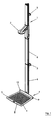
- FIG. 1 is a length measuring rod (1) provided with a head stop (2) for the head of a person to be measured and a base member (3) having a standing surface (4) for the person to be measured.
- the length measuring rod (1) has holding elements (5) for supporting a wall mounting.
- the length measuring rod (1) consists of individual rod segments (6), which can be combined in a modular manner.
- the base element (3) is positioned using a pressure element (7), which is movably guided in the region of the length measuring rod (1).
- a pressure element (7) which is movably guided in the region of the length measuring rod (1).
- Stand surface (4) is preferably a surface profiling (8) arranged to assist a secure standing of the person to be measured.
- the Oberlächenprofilierung can be realized for example in the form ofappelumrissen.
- the pressure element (7) is angular and has a horizontal leg (9) and a vertical leg (10).
- the vertical leg (10) serves as a heel stop.
- the base member (3) may be formed of a solid or flexible material. In particular, it is intended to use plastics or elastomeric materials.
- Fig. 2 shows the base member (3) in a separate from the pressing element (7) state. It can be seen that the base element (3) in the illustrated embodiment has two connection profiles (11).
- the connecting profiles (11) are adapted to counter profiles (12), which are arranged in the region of the pressure element (7), but in Fig. 2 are not recognizable.
- the connecting profile (11) may be formed, for example, as a recess or a pin.
- Fig. 3 shows a partially assembled state of the base member (3).
- the base element (3) is in this case already with a connection profile (11) in the in Fig. 3 also not recognizable counter profile (12) of the pressure element (7) has been inserted.
- This connection process is preferably carried out in a relative to the pressure element (7) horizontally pivoted positioning of the base element (3).
- After a pivoting of the base element (3) in the ground state according to Fig. 1 are then further connection profiles (11) aligned with the respective counter profiles (12).
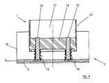
- Fig. 4 shows in a longitudinal section the displaceable guide of the pressure element (7) in the region of the length measuring rod (1). Below the pressure element (7), the base element (3) is arranged.
- the length measuring rod (1) has a wall (13).
- the wall (13) supports a bearing (14), in which the pressure element (7) is guided with at least one alignment element (15).
- the pressure element (7) is guided with at least one alignment element (15).
- two alignment elements (15) are used.
- the alignment elements (15) may be formed like a bolt.
- the horizontal leg (9) is supported by springs (16) opposite the length measuring rod (1).
- the springs (16) With a displacement of the pressure element (7) along a longitudinal axis (17) of the length measuring rod, the springs (16) are compressed and it is possible to position the base element (3) below the pressure element (7). After a corresponding positioning of the base element (3), the springs (16) press the pressure element (7) against the base element (3) and thereby fix the base element (3) in the region of a set-up surface.
Landscapes
- Health & Medical Sciences (AREA)
- Life Sciences & Earth Sciences (AREA)
- Physics & Mathematics (AREA)
- Heart & Thoracic Surgery (AREA)
- Molecular Biology (AREA)
- Dentistry (AREA)
- Biophysics (AREA)
- Pathology (AREA)
- Engineering & Computer Science (AREA)
- Biomedical Technology (AREA)
- General Physics & Mathematics (AREA)
- Medical Informatics (AREA)
- Oral & Maxillofacial Surgery (AREA)
- Surgery (AREA)
- Animal Behavior & Ethology (AREA)
- General Health & Medical Sciences (AREA)
- Public Health (AREA)
- Veterinary Medicine (AREA)
- A Measuring Device Byusing Mechanical Method (AREA)
- Length-Measuring Instruments Using Mechanical Means (AREA)
Description
- Die Erfindung betrifft eine Vorrichtung zur Längenmessung, die einen Längenmessstab mit Halteelementen für eine Wandmontage mit einer Messeinrichtung sowie ein Basiselement mit einer Standfläche für eine zu vermessende Person aufweist, sowie bei der das Basiselement relativ zum Längenmessstab fixierbar ist.
- Bei der Anwendung derartiger Vorrichtungen ist es zur Erreichung ausreichend exakter Messergebnisse erforderlich, daß die zu vermessende Person eine korrekte Lage relativ zum Längenmessstab einnimmt. Im Bereich der Standfläche können deshalb Positionierhilfen angeordnet werden. Die Positionierhilfen können beispielsweise Markierungen im Bereich der Standfläche und/oder ein Fersenanschlag sein.
- Bei einem Transport der Vorrichtung werden typischerweise der Längenmessstab und das Basiselement voneinander getrennt, um eine kompakte Transportdimensionierung zu unterstützen. Bei einer Inbetriebnahme ist es deshalb erforderlich, das Basiselement mit dem Längenmessstab zu verbinden. Die Verbindung soll dabei derart erfolgen, daß das Basiselement ausreichend fixiert ist, um auch bei einem Betreten durch eine Person und/oder bei seitlichen Stoßbelastungen eine exakte Positionierung beizubehalten.
- Aus der
DE 197 13 667 U1 ist eine Vorrichtung zur Längenmessung bekannt, die einen Längenmessstab mit einer Messeinrichtung sowie ein Basiselement mit einer Standfläche aufweist. Das Basiselement ist relativ zum Längenmessstab fixierbar. - Eine ähnliche Vorrichtung wird auch in der
US 2005/155246 A1 beschrieben. - Aus der
DE 19 84 779 U ist eine weitere Vorrichtung zur Längenmessung mit einer Messeinrichtung bekannt. Ein Basiselement ist relativ zum Längenmessstab fixierbar. - Auch die
DE 198 08 432 A1 erläutert eine Vorrichtung zur Längenmessung mit einem Längenmessstab und einer Messeinrichtung. - Aufgabe der vorliegenden Erfindung ist es daher, eine Vorrichtung der einleitend genannten Art derart zu konstruieren, daß eine einfache Montage und Demontage des Basiselementes unterstützt wird und eine zuverlässige Positionsfestlegung des Basiselementes erreicht wird.
- Diese Aufgabe wird erfindungsgemäß dadurch gelöst, daß das Basiselement durch mindestens ein am Längenmessstab beweglich geführtes Andruckelement zwischen Andruckelement und Fußboden festklemmbar ist.
- Durch die Festklemmbarkeit des Basiselementes ist es in einfacher weise und mit einem geringen Zeitaufwand möglich, eine Verbindung zwischen dem Basiselement und dem Längenmessstab herzustellen. Darüber hinaus wird das Basiselement relativ zur Aufstellfläche sichtbar fixiert, so daß die Positionierung des Basiselementes auch bei einer Benutzung sicher beibehalten wird. Durch die Möglichkeit einer schnellen Montage und Demontage des Basiselementes wird eine Reinigung eines Fußbodens unter dem Basiselement unterstützt. Vorzugsweise wird das Basiselement zwischen dem Andruckelement und dem Fußboden festgeklemmt.
- Hohe Andruckkräfte können dadurch bereitgestellt werden, daß das Andruckelement von mindestens einer Feder gegen das Basiselement gedrückt ist.
- Gemäß einer vereinfachten Ausführungsvariante ist auch daran gedacht, daß das Andruckelement durch die Einwirkung der Schwerkraft gegen das Basiselement gedrückt ist.
- Eine zuverlässige Positionsfestlegung des Basiselementes kann dadurch erfolgen, daß das Basiselement formschlüssig mit dem Andruckelement verbunden ist.
- Eine einfache Montage wird dadurch unterstützt, daß das Basiselement in einem teilmontiertem Zustand relativ zum Andruckelement verschwenkbar angeordnet ist.
- Eine definierte Positionierung der zu vermessenden Person wird dadurch erleichtert, daß das Andruckelement einen Fersenanschlag bereitstellt.
- Eine stabile Ausführungsform wird dadurch bereitgestellt, daß das Andruckelement mindestens bereichsweise als ein L-Profil ausgebildet ist. Ein anderes Ausführungsbeispiel betrifft eine T-Form.
- Die bewegliche Führung des Andruckelementes kann dadurch realisiert werden, daß das Andruckelement von mindestens einem Ausrichtelement im Bereich des Längenmessstabes geführt ist.
- Eine kompakte Ausführungsform wird dadurch bereitgestellt, daß im Bereich des Ausrichtelementes mindestens eine Feder angeordnet ist.
- Unbeabsichtigte Drehbewegungen können dadurch vermieden werden, daß das Andruckelement von mindestens zwei Ausrichtelementen im Bereich des Längenmessstabes geführt ist. Grundsätzlich ist aber ein Ausrichtelement ausreichend.
- Eine kompakte und zugleich stabile Ausführungsform wird dadurch bereitgestellt, daß das Ausrichtelement in einem mindestens bereichsweise von einer Wandung des Längenmessstabes umschlossenen Aufnahmeraum angeordnet ist, der beispielsweise durch ein Hohlprofil bereitgestellt wird. Gemäß einer anderen Ausführungsvariante ist auch daran gedacht, daß das Ausrichtelement außerhalb einer Wandung des Längenmessstabes angeordnet ist.
- In den Zeichnungen sind Ausführungsbeispiele der Erfindung schematisch dargestellt. Es zeigen:
- Fig. 1
- eine perspektivische Darstellung eines Längenmessstabes mit Kopfanschlag sowie einem Basiselement mit Standfläche,
- Fig. 2
- die Vorrichtung gemäß
Fig. 1 mit vom Längenmesstab getrenntem Basiselement, - Fig. 3
- die Vorrichtung gemäß
Fig. 2 nach einer Teilmontage des Basiselementes und - Fig. 4
- eine teilweise Darstellung eines Längsschnittes durch den Längenmessstab im Bereich eines Andruckelementes für das Basiselement.
- Gemäß der Ausführungsform in
Fig. 1 ist ein Längenmessstab (1) mit einem Kopfanschlag (2) für den Kopf einer zu vermessenden Person sowie einem Basiselement (3) versehen, das eine Standfläche (4) für die zu vermessende Person aufweist. Der Längenmessstab (1) weist Halteelemente (5) zur Unterstützung einer Wandmontage auf. Beim dargestellten Ausführungsbeispiel besteht der Längenmessstab (1) aus einzelnen Stabsegmenten (6), die modulartig miteinander kombiniert werden können. - Das Basiselement (3) wird unter Verwendung eines Andruckelementes (7) positioniert, das beweglich im Bereich des Längenmessstabes (1) geführt ist. Im Bereich der Standfläche (4) ist vorzugsweise eine Oberflächenprofilierung (8) angeordnet, um ein sicheres Stehen der zu vermessenden Person zu unterstützen. Die Oberlächenprofilierung kann beispielsweise in Form von Fußumrissen realisiert werden.
- Beim dargestellten Ausführungsbeispiel ist das Andruckelement (7) winkelartig ausgebildet und weist einen Horizontalschenkel (9) sowie einen Vertikalschenkel (10) auf. Der Vertikalschenkel (10) dient als Fersenanschlag.
- Das Basiselement (3) kann aus einem festen oder flexiblen Material ausgebildet sein. Gedacht ist insbesondere an die Verwendung von Kunststoffen oder elastomeren Materialien.
-
Fig. 2 zeigt das Basiselement (3) in einem vom Andruckelement (7) getrennten Zustand. Es ist zu erkennen, daß das Basiselement (3) beim dargestellten Ausführungsbeispiel zwei Verbindungsprofile (11) aufweist. Die Verbindungsprofile (11) sind angepaßt an Gegenprofile (12) ausgebildet, die im Bereich des Andruckelementes (7) angeordnet, allerdings inFig. 2 nicht erkennbar sind. Das Verbindungsprofil (11) kann beispielsweise als eine Ausnehmung oder ein zapfen ausgebildet sein. -
Fig. 3 zeigt einen teilmontierten Zustand des Basiselementes (3). Das Basiselement (3) ist hierbei bereits mit einem Verbindungsprofil (11) in das inFig. 3 ebenfalls nicht erkennbare Gegenprofil (12) des Andruckelementes (7) eingefügt worden. Dieser Verbindungsvorgang erfolgt vorzugsweise in einer relativ zum Andruckelement (7) horizontal verschwenkten Positionierung des Basiselementes (3). Nach einem Verschwenken des Basiselementes (3) in den Grundzustand gemäßFig. 1 sind dann weitere Verbindungsprofile (11) zu den jeweiligen Gegenprofilen (12) ausgerichtet. -
Fig. 4 zeigt in einem Längsschnitt die verschiebliche Führung des Andruckelementes (7) im Bereich des Längenmessstabes (1). Unterhalb des Andruckelementes (7) ist das Basiselement (3) angeordnet. - Aus
Fig. 4 ist zu erkennen, daß der Längenmessstab (1) eine Wandung (13) aufweist. Die Wandung (13) haltert ein Lager (14), in dem das Andruckelement (7) mit mindestens einem Ausrichtelement (15) geführt ist. Beim dargestellten Ausführungsbeispiel werden zwei Ausrichtelemente (15) verwendet. Die Ausrichtelemente (15) können bolzenartig ausgebildet sein. - Gemäß dem Ausführungsbeispiel in
Fig. 4 stützt sich der Horizontalschenkel (9) mit Federn (16) gegenüber dem Längenmessstab (1) ab. Bei einer Verschiebung des Andruckelementes (7) entlang einer Längsachse (17) des Längenmessstabes werden die Federn (16) zusammengedrückt und es ist möglich, das Basiselement (3) unterhalb des Andruckelementes (7) zu positionieren. Nach einer entsprechenden Positionierung des Basiselementes (3) drücken die Federn (16) das Andruckelement (7) gegen das Basiselement (3) und fixieren hierdurch das Basiselement (3) im Bereich einer Aufstellfläche.
Claims (13)
- Vorrichtung zur Längenmessung, die einen Längenmessstab (1) mit Halteelementen (5) zur Wandmontage mit einer Messeinrichtung sowie ein Basiselement (3) mit einer Standfläche (4) für eine zu vermessende Person aufweist, sowie bei der das Basiselement (3) relativ zum Längenmessstab (1) fixierbar ist, dadurch gekennzeichnet, daß das Basiselement (3) durch mindestens ein am Längenmessstab (1) beweglich geführtes Andruckelement (7) zwischen Andruckelement (7) und Fußboden festklemmbar ist.
- Vorrichtung nach Anspruch 1, dadurch gekennzeichnet, daß das Andruckelement (7) von mindestens einer Feder (16) gegen das Basiselement (3) gedrückt ist.
- Vorrichtung nach Anspruch 1, dadurch gekennzeichnet, daß das Andruckelement durch die Einwirkung der Schwerkraft gegen das Basiselement (3) gedrückt ist.
- Vorrichtung nach einem der Ansprüche 1 bis 3, dadurch gekennzeichnet, daß das Basiselement (3) formschlüssig mit dem Andruckelement (7) verbunden ist.
- verfahren nach einem der Ansprüche 1 bis 4, dadurch gekennzeichnet, daß das Basiselement (3) in einem teilmontiertem Zustand relativ zum Andruckelement (7) verschwenkbar angeordnet ist.
- Vorrichtung nach einem der Ansprüche 1 bis 5, dadurch gekennzeichnet, daß das Andruckelement (7) einen Fersenanschlag bereitstellt.
- Vorrichtung nach einem der Ansprüche 1 bis 6, dadurch gekennzeichnet, daß das Andruckelement (7) mindestens bereichsweise als ein L-Profil ausgebildet ist.
- Vorrichtung nach einem der Ansprüche 1 bis 7, dadurch gekennzeichnet, daß das Andruckelement (7) von mindestens einem Ausrichtelement (15) im Bereich des Längenmessstabes (1) geführt ist.
- Vorrichtung nach Anspruch 8, dadurch gekennzeichnet, daß im Bereich des Ausrichtelementes (15) mindestens eine Feder (16) angeordnet ist.
- Vorrichtung nach Anspruch 8, dadurch gekennzeichnet, daß das Andruckelement (7) von mindestens zwei Ausrichtelementen (15) im Bereich des Längenmessstabes (1) geführt ist.
- Vorrichtung nach einem der Ansprüche 8 bis 10, dadurch gekennzeichnet, daß das Ausrichtelement (15) in einem mindestens bereichsweise von einer Wandung (13) des Längenmessstabes (1) umschlossenen Aufnahmeraum angeordnet ist.
- Vorrichtung nach einem der Ansprüche 8 bis 10, dadurch gekennzeichnet, daß das Ausrichtelement (15) außerhalb einer Wandung (13) des Längenmessstabes (1) angeordnet ist.
- Vorrichtung nach einem der Ansprüche 1 bis 12, dadurch gekennzeichnet, daß das Andruckelement (7) am Basiselement (3) befestigt und zur Beaufschlagung des Längenmeßstabes (1) ausgebildet ist.
Applications Claiming Priority (1)
| Application Number | Priority Date | Filing Date | Title |
|---|---|---|---|
| DE201010022638 DE102010022638A1 (de) | 2010-05-31 | 2010-05-31 | Vorrichtung zur Längenmessung |
Publications (2)
| Publication Number | Publication Date |
|---|---|
| EP2389861A1 EP2389861A1 (de) | 2011-11-30 |
| EP2389861B1 true EP2389861B1 (de) | 2013-07-24 |
Family
ID=44509816
Family Applications (1)
| Application Number | Title | Priority Date | Filing Date |
|---|---|---|---|
| EP20110400024 Not-in-force EP2389861B1 (de) | 2010-05-31 | 2011-03-24 | Vorrichtung zur Längenmessung |
Country Status (2)
| Country | Link |
|---|---|
| EP (1) | EP2389861B1 (de) |
| DE (1) | DE102010022638A1 (de) |
Families Citing this family (3)
| Publication number | Priority date | Publication date | Assignee | Title |
|---|---|---|---|---|
| EP2532304A1 (de) * | 2011-06-06 | 2012-12-12 | medi GmbH & Co. KG | Messvorrichtung zum Erfassen eines Bein- und Fußlängenmaßes zum Anmessen von Strümpfen, insbesondere medizinischen Kompressionsstrümpfen |
| CN108814612B (zh) * | 2018-05-11 | 2020-09-15 | 中国人民解放军陆军军医大学第一附属医院 | 一种测量仪的自动清洁装置 |
| CN112458847B (zh) * | 2020-10-22 | 2022-01-25 | 中国一冶集团有限公司 | 沥青路面标高控制工具及其使用方法 |
Family Cites Families (5)
| Publication number | Priority date | Publication date | Assignee | Title |
|---|---|---|---|---|
| DE1984779U (de) * | 1967-10-13 | 1968-05-02 | Hans-Rudolf Dr Med Foerster | Laengenmessgeraet, insbesondere fuer medizinische zwecke. |
| US5088504A (en) * | 1990-10-23 | 1992-02-18 | National Upper Cervical Chiropractic Research Assn. | Machine and method for measuring skeletal misalignments |
| US6003235A (en) * | 1997-07-18 | 1999-12-21 | Chen; Han-Liang | Folding collapsible body-height measuring gauge |
| DE19808432A1 (de) * | 1998-03-02 | 1999-09-09 | Keller | Transportables Körperlängenmeßgerät |
| US7200952B2 (en) * | 2004-01-20 | 2007-04-10 | Tanita Corporation | Bioinstrumentation apparatus with height measuring device |
-
2010
- 2010-05-31 DE DE201010022638 patent/DE102010022638A1/de not_active Ceased
-
2011
- 2011-03-24 EP EP20110400024 patent/EP2389861B1/de not_active Not-in-force
Also Published As
| Publication number | Publication date |
|---|---|
| DE102010022638A1 (de) | 2011-12-01 |
| EP2389861A1 (de) | 2011-11-30 |
Similar Documents
| Publication | Publication Date | Title |
|---|---|---|
| DE2502619B2 (de) | Bausatz zum Aufbau eines zur Aufnahme von Instrumenten, insbesondere Laborinstrumenten, bestimmten Gestells | |
| DE102009046944A1 (de) | Montagesystem und Verfahren zur Montage einer Trennwand an eine Halteeinrichtung sowie Vorrichtung zum Trennen von Bereichen | |
| DE102012004128A1 (de) | Standardisiertes Befestigungssystem für Photovoltaikmodule und Montageverfahren | |
| DE102015223762A1 (de) | Schalungsteil und Deckenschalung mit einem solchen Schalungsteil | |
| EP2389861A1 (de) | Vorrichtung zur Längenmessung | |
| EP2267242B1 (de) | Wechselkonsole | |
| EP2216465B1 (de) | Voreilende Geländervorrichtung und Montageverfahren hierfür | |
| EP2193971B1 (de) | Wagenkasten eines Schienenfahrzeugs mit darin eingebauter Nasszelle | |
| DE8331778U1 (de) | Einrichtung zum aufhaengen von rasterdecken bzw. von rasterdeckenelementen | |
| DE202005003790U1 (de) | Fahrbares Schalgerüst | |
| DE8335937U1 (de) | Untermatratze mit quertraegern und elastischen verbindungsstuecken | |
| DE202009012348U1 (de) | Verstellbeschlag zur Härteregulierung einer Matratzenunterfederung | |
| DE9304403U1 (de) | Seilbahn für Kinderspielplätze | |
| EP1333257A1 (de) | Anordnung zur Überwachung des Füllungsgrades von einzelnen Behältern in einem Lagersystem | |
| DE202016002259U1 (de) | Hindernis für den Reitsport | |
| AT310232B (de) | Überbrückungsvorrichtung für Dehnfugen in Fahrbahnen und Gehwegen | |
| DE202014106101U1 (de) | Filterhalter und Halteklammer für einen Filterhalter | |
| DE688592C (de) | Lehrgeruest zur Flugzeugherstellung | |
| DE202009015280U1 (de) | Arbeits- und Montagebock | |
| AT14495U1 (de) | Vorrichtung zum Befestigen von Profilen an einer Unterkonstruktion | |
| DE202011101311U1 (de) | Lagerungselement einer Querlatte eines Bettlattenrostes | |
| DE9004260U1 (de) | Drehmoment-Kalibrierstand | |
| CH510788A (de) | Uberbrückungsvorrichtung für Dehnfugen in Fahrbahnen und Gehwegen | |
| DE2926908A1 (de) | Stuetzvorrichtung fuer ein deckenschalungselement | |
| DE202005011324U1 (de) | Halterungsgesamtheit eines Schuhs auf einem Gleitbrett, insbesondere einem Alpinski |
Legal Events
| Date | Code | Title | Description |
|---|---|---|---|
| AK | Designated contracting states |
Kind code of ref document: A1 Designated state(s): AL AT BE BG CH CY CZ DE DK EE ES FI FR GB GR HR HU IE IS IT LI LT LU LV MC MK MT NL NO PL PT RO RS SE SI SK SM TR |
|
| AX | Request for extension of the european patent |
Extension state: BA ME |
|
| PUAI | Public reference made under article 153(3) epc to a published international application that has entered the european phase |
Free format text: ORIGINAL CODE: 0009012 |
|
| 17P | Request for examination filed |
Effective date: 20111025 |
|
| 17Q | First examination report despatched |
Effective date: 20121211 |
|
| GRAP | Despatch of communication of intention to grant a patent |
Free format text: ORIGINAL CODE: EPIDOSNIGR1 |
|
| GRAS | Grant fee paid |
Free format text: ORIGINAL CODE: EPIDOSNIGR3 |
|
| GRAA | (expected) grant |
Free format text: ORIGINAL CODE: 0009210 |
|
| AK | Designated contracting states |
Kind code of ref document: B1 Designated state(s): AL AT BE BG CH CY CZ DE DK EE ES FI FR GB GR HR HU IE IS IT LI LT LU LV MC MK MT NL NO PL PT RO RS SE SI SK SM TR |
|
| REG | Reference to a national code |
Ref country code: GB Ref legal event code: FG4D Free format text: NOT ENGLISH |
|
| REG | Reference to a national code |
Ref country code: CH Ref legal event code: EP |
|
| REG | Reference to a national code |
Ref country code: AT Ref legal event code: REF Ref document number: 622914 Country of ref document: AT Kind code of ref document: T Effective date: 20130815 |
|
| REG | Reference to a national code |
Ref country code: IE Ref legal event code: FG4D Free format text: LANGUAGE OF EP DOCUMENT: GERMAN |
|
| REG | Reference to a national code |
Ref country code: DE Ref legal event code: R096 Ref document number: 502011001086 Country of ref document: DE Effective date: 20131002 |
|
| REG | Reference to a national code |
Ref country code: NL Ref legal event code: VDEP Effective date: 20130724 |
|
| REG | Reference to a national code |
Ref country code: LT Ref legal event code: MG4D |
|
| PG25 | Lapsed in a contracting state [announced via postgrant information from national office to epo] |
Ref country code: LT Free format text: LAPSE BECAUSE OF FAILURE TO SUBMIT A TRANSLATION OF THE DESCRIPTION OR TO PAY THE FEE WITHIN THE PRESCRIBED TIME-LIMIT Effective date: 20130724 Ref country code: SE Free format text: LAPSE BECAUSE OF FAILURE TO SUBMIT A TRANSLATION OF THE DESCRIPTION OR TO PAY THE FEE WITHIN THE PRESCRIBED TIME-LIMIT Effective date: 20130724 Ref country code: IS Free format text: LAPSE BECAUSE OF FAILURE TO SUBMIT A TRANSLATION OF THE DESCRIPTION OR TO PAY THE FEE WITHIN THE PRESCRIBED TIME-LIMIT Effective date: 20131124 Ref country code: CY Free format text: LAPSE BECAUSE OF FAILURE TO SUBMIT A TRANSLATION OF THE DESCRIPTION OR TO PAY THE FEE WITHIN THE PRESCRIBED TIME-LIMIT Effective date: 20130731 Ref country code: HR Free format text: LAPSE BECAUSE OF FAILURE TO SUBMIT A TRANSLATION OF THE DESCRIPTION OR TO PAY THE FEE WITHIN THE PRESCRIBED TIME-LIMIT Effective date: 20130724 Ref country code: PT Free format text: LAPSE BECAUSE OF FAILURE TO SUBMIT A TRANSLATION OF THE DESCRIPTION OR TO PAY THE FEE WITHIN THE PRESCRIBED TIME-LIMIT Effective date: 20131125 Ref country code: NO Free format text: LAPSE BECAUSE OF FAILURE TO SUBMIT A TRANSLATION OF THE DESCRIPTION OR TO PAY THE FEE WITHIN THE PRESCRIBED TIME-LIMIT Effective date: 20131024 |
|
| PG25 | Lapsed in a contracting state [announced via postgrant information from national office to epo] |
Ref country code: GR Free format text: LAPSE BECAUSE OF FAILURE TO SUBMIT A TRANSLATION OF THE DESCRIPTION OR TO PAY THE FEE WITHIN THE PRESCRIBED TIME-LIMIT Effective date: 20131025 Ref country code: FI Free format text: LAPSE BECAUSE OF FAILURE TO SUBMIT A TRANSLATION OF THE DESCRIPTION OR TO PAY THE FEE WITHIN THE PRESCRIBED TIME-LIMIT Effective date: 20130724 Ref country code: PL Free format text: LAPSE BECAUSE OF FAILURE TO SUBMIT A TRANSLATION OF THE DESCRIPTION OR TO PAY THE FEE WITHIN THE PRESCRIBED TIME-LIMIT Effective date: 20130724 Ref country code: LV Free format text: LAPSE BECAUSE OF FAILURE TO SUBMIT A TRANSLATION OF THE DESCRIPTION OR TO PAY THE FEE WITHIN THE PRESCRIBED TIME-LIMIT Effective date: 20130724 Ref country code: SI Free format text: LAPSE BECAUSE OF FAILURE TO SUBMIT A TRANSLATION OF THE DESCRIPTION OR TO PAY THE FEE WITHIN THE PRESCRIBED TIME-LIMIT Effective date: 20130724 Ref country code: NL Free format text: LAPSE BECAUSE OF FAILURE TO SUBMIT A TRANSLATION OF THE DESCRIPTION OR TO PAY THE FEE WITHIN THE PRESCRIBED TIME-LIMIT Effective date: 20130724 |
|
| PG25 | Lapsed in a contracting state [announced via postgrant information from national office to epo] |
Ref country code: CY Free format text: LAPSE BECAUSE OF FAILURE TO SUBMIT A TRANSLATION OF THE DESCRIPTION OR TO PAY THE FEE WITHIN THE PRESCRIBED TIME-LIMIT Effective date: 20130724 |
|
| PG25 | Lapsed in a contracting state [announced via postgrant information from national office to epo] |
Ref country code: RO Free format text: LAPSE BECAUSE OF FAILURE TO SUBMIT A TRANSLATION OF THE DESCRIPTION OR TO PAY THE FEE WITHIN THE PRESCRIBED TIME-LIMIT Effective date: 20130724 Ref country code: EE Free format text: LAPSE BECAUSE OF FAILURE TO SUBMIT A TRANSLATION OF THE DESCRIPTION OR TO PAY THE FEE WITHIN THE PRESCRIBED TIME-LIMIT Effective date: 20130724 Ref country code: CZ Free format text: LAPSE BECAUSE OF FAILURE TO SUBMIT A TRANSLATION OF THE DESCRIPTION OR TO PAY THE FEE WITHIN THE PRESCRIBED TIME-LIMIT Effective date: 20130724 Ref country code: DK Free format text: LAPSE BECAUSE OF FAILURE TO SUBMIT A TRANSLATION OF THE DESCRIPTION OR TO PAY THE FEE WITHIN THE PRESCRIBED TIME-LIMIT Effective date: 20130724 Ref country code: SK Free format text: LAPSE BECAUSE OF FAILURE TO SUBMIT A TRANSLATION OF THE DESCRIPTION OR TO PAY THE FEE WITHIN THE PRESCRIBED TIME-LIMIT Effective date: 20130724 |
|
| PG25 | Lapsed in a contracting state [announced via postgrant information from national office to epo] |
Ref country code: ES Free format text: LAPSE BECAUSE OF FAILURE TO SUBMIT A TRANSLATION OF THE DESCRIPTION OR TO PAY THE FEE WITHIN THE PRESCRIBED TIME-LIMIT Effective date: 20130724 Ref country code: IT Free format text: LAPSE BECAUSE OF FAILURE TO SUBMIT A TRANSLATION OF THE DESCRIPTION OR TO PAY THE FEE WITHIN THE PRESCRIBED TIME-LIMIT Effective date: 20130724 |
|
| PLBE | No opposition filed within time limit |
Free format text: ORIGINAL CODE: 0009261 |
|
| STAA | Information on the status of an ep patent application or granted ep patent |
Free format text: STATUS: NO OPPOSITION FILED WITHIN TIME LIMIT |
|
| 26N | No opposition filed |
Effective date: 20140425 |
|
| REG | Reference to a national code |
Ref country code: DE Ref legal event code: R097 Ref document number: 502011001086 Country of ref document: DE Effective date: 20140425 |
|
| PG25 | Lapsed in a contracting state [announced via postgrant information from national office to epo] |
Ref country code: LU Free format text: LAPSE BECAUSE OF FAILURE TO SUBMIT A TRANSLATION OF THE DESCRIPTION OR TO PAY THE FEE WITHIN THE PRESCRIBED TIME-LIMIT Effective date: 20140324 |
|
| REG | Reference to a national code |
Ref country code: CH Ref legal event code: PL |
|
| REG | Reference to a national code |
Ref country code: IE Ref legal event code: MM4A |
|
| PG25 | Lapsed in a contracting state [announced via postgrant information from national office to epo] |
Ref country code: CH Free format text: LAPSE BECAUSE OF NON-PAYMENT OF DUE FEES Effective date: 20140331 Ref country code: IE Free format text: LAPSE BECAUSE OF NON-PAYMENT OF DUE FEES Effective date: 20140324 Ref country code: LI Free format text: LAPSE BECAUSE OF NON-PAYMENT OF DUE FEES Effective date: 20140331 |
|
| PG25 | Lapsed in a contracting state [announced via postgrant information from national office to epo] |
Ref country code: MT Free format text: LAPSE BECAUSE OF FAILURE TO SUBMIT A TRANSLATION OF THE DESCRIPTION OR TO PAY THE FEE WITHIN THE PRESCRIBED TIME-LIMIT Effective date: 20130724 |
|
| REG | Reference to a national code |
Ref country code: FR Ref legal event code: PLFP Year of fee payment: 6 |
|
| PG25 | Lapsed in a contracting state [announced via postgrant information from national office to epo] |
Ref country code: SM Free format text: LAPSE BECAUSE OF FAILURE TO SUBMIT A TRANSLATION OF THE DESCRIPTION OR TO PAY THE FEE WITHIN THE PRESCRIBED TIME-LIMIT Effective date: 20130724 |
|
| PG25 | Lapsed in a contracting state [announced via postgrant information from national office to epo] |
Ref country code: MC Free format text: LAPSE BECAUSE OF FAILURE TO SUBMIT A TRANSLATION OF THE DESCRIPTION OR TO PAY THE FEE WITHIN THE PRESCRIBED TIME-LIMIT Effective date: 20130724 |
|
| PG25 | Lapsed in a contracting state [announced via postgrant information from national office to epo] |
Ref country code: BG Free format text: LAPSE BECAUSE OF FAILURE TO SUBMIT A TRANSLATION OF THE DESCRIPTION OR TO PAY THE FEE WITHIN THE PRESCRIBED TIME-LIMIT Effective date: 20130724 Ref country code: RS Free format text: LAPSE BECAUSE OF FAILURE TO SUBMIT A TRANSLATION OF THE DESCRIPTION OR TO PAY THE FEE WITHIN THE PRESCRIBED TIME-LIMIT Effective date: 20130724 |
|
| PG25 | Lapsed in a contracting state [announced via postgrant information from national office to epo] |
Ref country code: HU Free format text: LAPSE BECAUSE OF FAILURE TO SUBMIT A TRANSLATION OF THE DESCRIPTION OR TO PAY THE FEE WITHIN THE PRESCRIBED TIME-LIMIT; INVALID AB INITIO Effective date: 20110324 Ref country code: BE Free format text: LAPSE BECAUSE OF FAILURE TO SUBMIT A TRANSLATION OF THE DESCRIPTION OR TO PAY THE FEE WITHIN THE PRESCRIBED TIME-LIMIT Effective date: 20140331 Ref country code: TR Free format text: LAPSE BECAUSE OF FAILURE TO SUBMIT A TRANSLATION OF THE DESCRIPTION OR TO PAY THE FEE WITHIN THE PRESCRIBED TIME-LIMIT Effective date: 20130724 |
|
| REG | Reference to a national code |
Ref country code: FR Ref legal event code: PLFP Year of fee payment: 7 |
|
| REG | Reference to a national code |
Ref country code: AT Ref legal event code: MM01 Ref document number: 622914 Country of ref document: AT Kind code of ref document: T Effective date: 20160324 |
|
| PG25 | Lapsed in a contracting state [announced via postgrant information from national office to epo] |
Ref country code: AT Free format text: LAPSE BECAUSE OF NON-PAYMENT OF DUE FEES Effective date: 20160324 |
|
| REG | Reference to a national code |
Ref country code: FR Ref legal event code: PLFP Year of fee payment: 8 |
|
| PG25 | Lapsed in a contracting state [announced via postgrant information from national office to epo] |
Ref country code: MK Free format text: LAPSE BECAUSE OF FAILURE TO SUBMIT A TRANSLATION OF THE DESCRIPTION OR TO PAY THE FEE WITHIN THE PRESCRIBED TIME-LIMIT Effective date: 20130724 |
|
| PG25 | Lapsed in a contracting state [announced via postgrant information from national office to epo] |
Ref country code: AL Free format text: LAPSE BECAUSE OF FAILURE TO SUBMIT A TRANSLATION OF THE DESCRIPTION OR TO PAY THE FEE WITHIN THE PRESCRIBED TIME-LIMIT Effective date: 20130724 |
|
| REG | Reference to a national code |
Ref country code: DE Ref legal event code: R082 Ref document number: 502011001086 Country of ref document: DE Representative=s name: PATENTANWAELTE KLICKOW & WETZEL PARTGMBB, DE |
|
| PGFP | Annual fee paid to national office [announced via postgrant information from national office to epo] |
Ref country code: DE Payment date: 20240213 Year of fee payment: 14 Ref country code: GB Payment date: 20240320 Year of fee payment: 14 |
|
| PGFP | Annual fee paid to national office [announced via postgrant information from national office to epo] |
Ref country code: FR Payment date: 20240327 Year of fee payment: 14 |
|
| REG | Reference to a national code |
Ref country code: DE Ref legal event code: R119 Ref document number: 502011001086 Country of ref document: DE |
|
| GBPC | Gb: european patent ceased through non-payment of renewal fee |
Effective date: 20250324 |
|
| PG25 | Lapsed in a contracting state [announced via postgrant information from national office to epo] |
Ref country code: DE Free format text: LAPSE BECAUSE OF NON-PAYMENT OF DUE FEES Effective date: 20251001 |
|
| PG25 | Lapsed in a contracting state [announced via postgrant information from national office to epo] |
Ref country code: GB Free format text: LAPSE BECAUSE OF NON-PAYMENT OF DUE FEES Effective date: 20250324 |
|
| PG25 | Lapsed in a contracting state [announced via postgrant information from national office to epo] |
Ref country code: FR Free format text: LAPSE BECAUSE OF NON-PAYMENT OF DUE FEES Effective date: 20250331 |