EP2389253B1 - Solids discharge centrifugal separator with disposable contact elements - Google Patents
Solids discharge centrifugal separator with disposable contact elements Download PDFInfo
- Publication number
- EP2389253B1 EP2389253B1 EP09810788.1A EP09810788A EP2389253B1 EP 2389253 B1 EP2389253 B1 EP 2389253B1 EP 09810788 A EP09810788 A EP 09810788A EP 2389253 B1 EP2389253 B1 EP 2389253B1
- Authority
- EP
- European Patent Office
- Prior art keywords
- bowl
- piston
- separator
- solids
- assembly
- Prior art date
- Legal status (The legal status is an assumption and is not a legal conclusion. Google has not performed a legal analysis and makes no representation as to the accuracy of the status listed.)
- Not-in-force
Links
- 239000007787 solid Substances 0.000 title claims description 109
- 239000007788 liquid Substances 0.000 claims description 49
- 230000037361 pathway Effects 0.000 claims description 42
- 239000012530 fluid Substances 0.000 claims description 33
- 238000000034 method Methods 0.000 claims description 20
- 239000000463 material Substances 0.000 claims description 16
- 238000002955 isolation Methods 0.000 claims description 12
- 239000000110 cooling liquid Substances 0.000 claims description 9
- 238000001816 cooling Methods 0.000 claims description 7
- 230000009977 dual effect Effects 0.000 claims description 7
- 239000004033 plastic Substances 0.000 claims description 7
- 230000001105 regulatory effect Effects 0.000 claims 2
- 239000007789 gas Substances 0.000 description 32
- 230000000712 assembly Effects 0.000 description 9
- 238000000429 assembly Methods 0.000 description 9
- 238000000926 separation method Methods 0.000 description 9
- 238000013461 design Methods 0.000 description 6
- 230000003287 optical effect Effects 0.000 description 6
- 230000008569 process Effects 0.000 description 6
- 238000012545 processing Methods 0.000 description 6
- 238000012864 cross contamination Methods 0.000 description 4
- 238000007789 sealing Methods 0.000 description 4
- 239000000126 substance Substances 0.000 description 4
- 238000011109 contamination Methods 0.000 description 3
- 238000007599 discharging Methods 0.000 description 3
- 230000005484 gravity Effects 0.000 description 3
- 238000004519 manufacturing process Methods 0.000 description 3
- 238000010926 purge Methods 0.000 description 3
- 238000011084 recovery Methods 0.000 description 3
- XKRFYHLGVUSROY-UHFFFAOYSA-N Argon Chemical compound [Ar] XKRFYHLGVUSROY-UHFFFAOYSA-N 0.000 description 2
- IJGRMHOSHXDMSA-UHFFFAOYSA-N Atomic nitrogen Chemical compound N#N IJGRMHOSHXDMSA-UHFFFAOYSA-N 0.000 description 2
- 230000009471 action Effects 0.000 description 2
- 239000012190 activator Substances 0.000 description 2
- 239000012620 biological material Substances 0.000 description 2
- 230000000694 effects Effects 0.000 description 2
- 239000008241 heterogeneous mixture Substances 0.000 description 2
- 230000036512 infertility Effects 0.000 description 2
- 230000007246 mechanism Effects 0.000 description 2
- 239000002184 metal Substances 0.000 description 2
- 239000000203 mixture Substances 0.000 description 2
- 230000010355 oscillation Effects 0.000 description 2
- XLYOFNOQVPJJNP-UHFFFAOYSA-N water Substances O XLYOFNOQVPJJNP-UHFFFAOYSA-N 0.000 description 2
- 230000001133 acceleration Effects 0.000 description 1
- 239000003570 air Substances 0.000 description 1
- 230000004075 alteration Effects 0.000 description 1
- 229910052786 argon Inorganic materials 0.000 description 1
- 230000015572 biosynthetic process Effects 0.000 description 1
- 238000004364 calculation method Methods 0.000 description 1
- 239000006285 cell suspension Substances 0.000 description 1
- 238000004140 cleaning Methods 0.000 description 1
- 230000000295 complement effect Effects 0.000 description 1
- 239000002826 coolant Substances 0.000 description 1
- 239000000498 cooling water Substances 0.000 description 1
- 238000013500 data storage Methods 0.000 description 1
- 230000001627 detrimental effect Effects 0.000 description 1
- 238000006073 displacement reaction Methods 0.000 description 1
- -1 e.g. Substances 0.000 description 1
- 238000000605 extraction Methods 0.000 description 1
- 239000006260 foam Substances 0.000 description 1
- 230000006870 function Effects 0.000 description 1
- 238000010438 heat treatment Methods 0.000 description 1
- 238000009434 installation Methods 0.000 description 1
- 239000011344 liquid material Substances 0.000 description 1
- 238000012423 maintenance Methods 0.000 description 1
- 230000013011 mating Effects 0.000 description 1
- 229910052757 nitrogen Inorganic materials 0.000 description 1
- 102000039446 nucleic acids Human genes 0.000 description 1
- 108020004707 nucleic acids Proteins 0.000 description 1
- 150000007523 nucleic acids Chemical class 0.000 description 1
- 238000002360 preparation method Methods 0.000 description 1
- 238000011028 process validation Methods 0.000 description 1
- 102000004169 proteins and genes Human genes 0.000 description 1
- 108090000623 proteins and genes Proteins 0.000 description 1
- 230000004044 response Effects 0.000 description 1
- 230000000717 retained effect Effects 0.000 description 1
- 230000002441 reversible effect Effects 0.000 description 1
- 238000004062 sedimentation Methods 0.000 description 1
- 230000001954 sterilising effect Effects 0.000 description 1
- 238000003860 storage Methods 0.000 description 1
- 238000006467 substitution reaction Methods 0.000 description 1
Images


Classifications
-
- B—PERFORMING OPERATIONS; TRANSPORTING
- B04—CENTRIFUGAL APPARATUS OR MACHINES FOR CARRYING-OUT PHYSICAL OR CHEMICAL PROCESSES
- B04B—CENTRIFUGES
- B04B7/00—Elements of centrifuges
- B04B7/08—Rotary bowls
- B04B7/12—Inserts, e.g. armouring plates
-
- B—PERFORMING OPERATIONS; TRANSPORTING
- B04—CENTRIFUGAL APPARATUS OR MACHINES FOR CARRYING-OUT PHYSICAL OR CHEMICAL PROCESSES
- B04B—CENTRIFUGES
- B04B11/00—Feeding, charging, or discharging bowls
- B04B11/02—Continuous feeding or discharging; Control arrangements therefor
-
- B—PERFORMING OPERATIONS; TRANSPORTING
- B04—CENTRIFUGAL APPARATUS OR MACHINES FOR CARRYING-OUT PHYSICAL OR CHEMICAL PROCESSES
- B04B—CENTRIFUGES
- B04B11/00—Feeding, charging, or discharging bowls
- B04B11/04—Periodical feeding or discharging; Control arrangements therefor
-
- B—PERFORMING OPERATIONS; TRANSPORTING
- B04—CENTRIFUGAL APPARATUS OR MACHINES FOR CARRYING-OUT PHYSICAL OR CHEMICAL PROCESSES
- B04B—CENTRIFUGES
- B04B11/00—Feeding, charging, or discharging bowls
- B04B11/04—Periodical feeding or discharging; Control arrangements therefor
- B04B11/05—Base discharge
-
- B—PERFORMING OPERATIONS; TRANSPORTING
- B04—CENTRIFUGAL APPARATUS OR MACHINES FOR CARRYING-OUT PHYSICAL OR CHEMICAL PROCESSES
- B04B—CENTRIFUGES
- B04B13/00—Control arrangements specially designed for centrifuges; Programme control of centrifuges
-
- B—PERFORMING OPERATIONS; TRANSPORTING
- B04—CENTRIFUGAL APPARATUS OR MACHINES FOR CARRYING-OUT PHYSICAL OR CHEMICAL PROCESSES
- B04B—CENTRIFUGES
- B04B15/00—Other accessories for centrifuges
- B04B15/02—Other accessories for centrifuges for cooling, heating, or heat insulating
-
- B—PERFORMING OPERATIONS; TRANSPORTING
- B04—CENTRIFUGAL APPARATUS OR MACHINES FOR CARRYING-OUT PHYSICAL OR CHEMICAL PROCESSES
- B04B—CENTRIFUGES
- B04B9/00—Drives specially designed for centrifuges; Arrangement or disposition of transmission gearing; Suspending or balancing rotary bowls
- B04B9/08—Arrangement or disposition of transmission gearing ; Couplings; Brakes
-
- B—PERFORMING OPERATIONS; TRANSPORTING
- B04—CENTRIFUGAL APPARATUS OR MACHINES FOR CARRYING-OUT PHYSICAL OR CHEMICAL PROCESSES
- B04B—CENTRIFUGES
- B04B9/00—Drives specially designed for centrifuges; Arrangement or disposition of transmission gearing; Suspending or balancing rotary bowls
- B04B9/12—Suspending rotary bowls ; Bearings; Packings for bearings
-
- B—PERFORMING OPERATIONS; TRANSPORTING
- B04—CENTRIFUGAL APPARATUS OR MACHINES FOR CARRYING-OUT PHYSICAL OR CHEMICAL PROCESSES
- B04B—CENTRIFUGES
- B04B5/00—Other centrifuges
- B04B5/04—Radial chamber apparatus for separating predominantly liquid mixtures, e.g. butyrometers
- B04B5/0442—Radial chamber apparatus for separating predominantly liquid mixtures, e.g. butyrometers with means for adding or withdrawing liquid substances during the centrifugation, e.g. continuous centrifugation
- B04B2005/0485—Radial chamber apparatus for separating predominantly liquid mixtures, e.g. butyrometers with means for adding or withdrawing liquid substances during the centrifugation, e.g. continuous centrifugation with a displaceable piston in the centrifuge chamber
Definitions
- centrifugal separators are known for separating heterogeneous mixtures into components based on specific gravity.
- a heterogeneous mixture which may also be referred to as feed material or liquid
- the rotating bowl spins at high speeds and forces components of the mixture that have a high specific gravity to separate therefrom by sedimentation.
- dense solids compress as a cake tightly against an inner surface or wall of the bowl and clarified liquid, or centrate, forms radially inward from the cake.
- the bowl may spin at speeds sufficient to produce forces 20,000 times greater than gravity so as to separate the solids from the centrate.
- the separator As solids accumulate along the wall of the bowl, the centrate exits from the bowl and leaves the separator. Once a desired amount of solids has accumulated, the separator is placed in a discharge mode in which the solids are removed from the separator. Often, for example, an internal scraper is engaged to scrape the solids from the walls of the bowl.
- separators have many shortcomings when discharging particular kinds of solids and liquids. For example, some separators may not be capable of completely discharging solids that are sticky, which can result in poor yields. A poor yield can be especially problematic for high-value solids such as those encountered in pharmaceutical processes.
- Traditional separators also subject a feed material to very high shear forces when accelerating the material to the rotational speed of the bowl, which can damage, for example, sensitive chemical or biological substances such as intact cells.
- Other separators do not provide a convenient means by which to handle and recover sensitive solids. For example, an operator is commonly required to assist with solids discharge and recovery, introducing the potential for contamination.
- conventional separators tend to be difficult to clean or sterilize in place, requiring operations that significantly increase maintenance costs and creating the potential for cross contamination between different preparations.
- the assembly includes a bowl liner, a hollow central core, a first piston assembly, and a second piston assembly.
- the bowl liner conforms to the inner wall of the bowl of the separator.
- the separator bowl includes an upper portion, a cylindrical middle portion, and a conical lower portion.
- the upper portion of the bowl includes a spindle shaft capable of engaging a drive motor.
- the spindle shaft terminates at its upper end in an outlet port, and the lower portion of the bowl includes a cylindrical extension terminating at its lower end in an inlet/solids discharge port.
- the bowl liner extends continuously from the inlet port to the outlet port, and forms the entire sample contacting surface along the walls of the bowl.
- the hollow central core is disposed about the central axis of the bowl and extends from the liner at the spindle shaft to the liner at its lower extension.
- the first piston is movably disposed within the liner and conforms to the inner surface of the liner.
- the first piston also surrounds the central core.
- the second piston is movably disposed within the central core and conforms to the inner surface of the central core.
- the second piston is capable of extension through the cylindrical extension to discharge the last remaining solids from the bowl, after the first piston has extruded the bulk of the solids from the bowl.
- the bowl liner and other components of the assembly each optionally may be made of plastic, and the bowl liner assembly is preferably configured as a single disposable unit, which can be provided in pre-sterilized condition.
- the central core is fitted with channels for a driving fluid or gas that drives one or both of the first and second pistons.
- the liner assembly is configured for use with a separator bowl that possesses a removable lower end, thereby permitting the bowl to be opened for replacement of the bowl assembly.
- the separator contains a dual piston separator bowl assembly, which includes a separator bowl, a hollow central core, a first piston, and a second piston.
- the separator bowl has an upper portion, a cylindrical middle portion, and a conical lower portion.
- the upper portion of the bowl includes a spindle shaft capable of engaging a drive motor.
- the spindle shaft terminates at its upper end in an outlet port, and the lower portion of the bowl includes a cylindrical extension terminating at its lower end in an inlet/solids discharge port.
- the hollow central core is disposed about the central axis of the bowl and extends from the spindle shaft to the lower extension of the bowl.
- the first piston is movably disposed within the bowl and conforms to the inner surface of the bowl.
- the first piston also surrounds the central core.
- the second piston is movably disposed within the central core and conforms to the inner surface of the central core.
- the second piston is capable of extension through the cylindrical extension to discharge the last remaining solids from the bowl, after the first piston has extruded the bulk of the solids from the bowl.
- the lower portion of the separator bowl is removable, and can be attached with a lower portion lock nut.
- the separator also includes a bowl liner, a centrate valve assembly, a feed/discharge valve assembly, or a piston position sensing system.
- the piston position sensing system can be configured to measure the position of the first and/or second pistons within the bowl during operation.
- Some embodiments of the separator also may include a variable speed vector-type drive motor with speed and angular position sensing.
- Certain embodiments of the separator also include a piston air supply actuator, which can be driven up or down by ports supplying a drive gas.
- the separator is hermetically sealed by seal/sleeve assemblies at the upper and lower ends of the separator bowl, or bowl liner. The seals can be provided with cooling ports and drain ports for a cooling liquid flow to cool the seals and seal assemblies.
- the separator includes structures to maintain stability and dampen oscillation.
- Such structures include an upper bearing assembly with a spherical or partially spherical mounting, and upper and lower bearing assemblies having anti-rotation pins.
- the separator bowl is surrounded by a housing containing a cooling jacket. In some embodiments the housing can be separated into upper and lower portions.
- the separator includes one or more disposable elements such as a disposable bowl liner, a disposable bowl liner/first piston assembly, a disposable separator bowl/bowl liner/first piston assembly, a disposable centrate valve assembly, a disposable second piston assembly, a disposable centrate valve/second piston assembly, or a disposable feed/discharge valve assembly.
- all sample contacting surfaces of the separator are disposable. In some embodiments, all sample contacting surfaces of the separator are disposable and the separator is hermetically sealed.
- step (a) a feed liquid is flowed into the separator bowl through the inlet port.
- step (b) the separator bowl is rotated, whereby solid components of the feed liquid accumulate on the inner surface of the bowl.
- step (c) the bowl continues to rotate while feed liquid flows into the inlet port, and a clarified centrate liquid flows out through the outlet port.
- step (d) the rotation of the bowl is halted and residual liquid is drained from the bowl through the inlet port.
- step (e) a pressurized fluid or drive gas is driven into the bowl, whereby the first piston is displaced downward within the bowl and accumulated solids are discharged through the inlet port.
- step (f) an actuator for the second piston is driven downward, whereby the second piston moves downward within the central core and causes the final residual solids to be discharged through the inlet port.
- the method also includes step (g), introducing a pressurized fluid or gas through the inlet port into the bowl, whereby the first piston is displaced upward in the bowl.
- the separator includes one or more disposable components, and the method includes step (h), replacing one or more of the disposable components prior to repeating step (a).
- steps (a) through (g) or (a) through (h) are repeated for two or more cycles of operation with a single type of feed liquid, or with switching over to a different type of feed liquid between cycles.
- a piston position sensing system is used to track the motion of the first and/or second pistons within the bowl during any of steps (a) through (g).
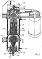
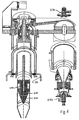
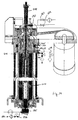
- FIG. 1 shows an embodiment of a centrifugal separator according to the invention in vertical section, with a middle section removed.
- Separator 100 includes separator bowl 150, separator housing 110, and variable speed drive motor 300.
- the housing has upper, middle, and lower portions.
- the middle portion of the separator housing encloses separator bowl 150.
- this portion of the housing is temperature controlled by fluid jacket 113 for flowing a controlled temperature fluid, such as water, in through cooling inlet port 114 in the lower portion of the housing and out through cooling outlet port 116 near the top of the middle portion of the housing.
- a controlled temperature fluid such as water
- the fluid jacket of the housing can be used either to cool or warm the centrifuge interior, and therefore the sample during separation.
- cooling water for example to a temperature such as 4°C, in order to preserve the structure and function of biological materials such as cells, proteins, or nucleic acids.
- the upper portion of the housing contains upper bearing assembly 115 that engages spindle shaft 160 which extends upwardly from the separator bowl.
- the bearing assembly 115 includes a semi-spherical upper portion, a short cylindrical middle portion, and a lower semi-hemispherical portion.
- the semi-spherical portions can rest against mating surfaces of one or more seats.
- An exemplary semi-spherical portion that can be employed in a separator of the invention has been described by U.S. Patent No. 6,986,734 , which is hereby incorporated by reference.
- the lower portion of the housing includes feed cone and lower bearing assembly 120.
- the feed cone serves as the lower portion of the bowl, and attaches to the upper portion of the bowl by means of feed cone lock nut 122, which attaches to a thread at the bottom of the cylindrical bowl portion.
- the lower bearing assembly is integral with lower bowl extension 154 that extends downward from the feed cone.
- Bowl lock handles 124 are used to secure the bowl during attachment or removal of the feed cone and lower bearing assembly.
- the lower portion of the housing can be opened by removing lower housing clamp ring 112 for accessing the feed cone and bowl assembly.
- Other features of the upper and lower housing portions are the lower (117) and upper (118) anti-rotation pins and rubber oscillation restraint ring 119.
- Separator bowl 150 has a cylindrical upper portion and a conical lower portion.
- the lower portion of the bowl includes inlet port 170 at the bottom of the bowl, through which feed liquid is pumped during the feed mode of operation. Rotation of the bowl causes the feed liquid to rise up the inner surface of the conical lower end of the bowl and move radially outward. Solids then separate from the feed liquid and accumulate along the inner surface of the bowl, for example, as a cake.
- Spindle shaft 160 engages drive belt 310 through drive pulley 162.
- Outlet port 180 at the top of the spindle shaft allows centrate to exit the bowl.
- the bowl By positioning the inlet and outlet ports at the bottom and top of the bowl, respectively, the bowl can be filled gently and completely with feed liquid from bottom to top of the bowl, leaving no air, so as to avoid or minimize the formation of bubbles or foam that could harm sample components, e.g., through surface tension effects and shear forces that result with other designs.
- Piston 200 is disposed within the bowl liner 220.
- the piston features an upper portion that conforms to the upper portion of the bowl liner and a lower portion that conforms to the lower portion of the bowl liner.
- the upper portion of the piston is cylindrical, and the lower portion is conical in form.
- the piston is capable of moving up and down along the central axis of the bowl. During the feed mode of operation the piston is raised to the top of the bowl, and during the solids discharge mode of operation the piston is gradually lowered in the bowl to displace the accumulated solids from the inner wall of the bowl liner and out through the inlet port at the bottom of the bowl.
- the lower end of the bowl liner and the lower portion of the piston have closely complementary shapes, the lower surface of the piston fitting snugly within the bottom inner surface of the bowl liner, to achieve maximum discharge of solids in a single cycle of operation.
- the piston contains a fluid pathway for transport of fluid, such as feed liquid, centrate liquid, or a drive fluid (an inert liquid or gas) through the piston.
- fluid such as feed liquid, centrate liquid, or a drive fluid (an inert liquid or gas)
- shuttle valve 250 Disposed within the piston, and situated within the fluid pathway, is shuttle valve 250 that regulates fluid flow through the pathway in response to the pressure across the valve.
- Two alternative designs for the shuttle valve are depicted.
- a close-up view of a cylindrical or cog-shaped shuttle valve 250 is shown to the left of the separator, having a mirrored surface 260 at the top.
- An alternative ball-shaped shuttle valve 250 is depicted to the right of the separator; the ball has a mirrored surface. Seals can be added as appropriate to the piston cavity and/or to the shuttle valve to promote efficient sealing of the valve at its upper and lower limits of travel.
- the fluid pathway has two parts: a first pathway 212 opening at the top of the piston, extending along the central axis of the piston and ending at the upper side of the shuttle valve; and a second pathway 214 that communicates with the lower side of the shuttle valve and extends a passage radially outward, providing an opening in the lower, conical portion of the piston approximately at the middle thereof.
- the height of the second pathway along the piston axis is selected such that the pathway openings in the piston lower portion are at an appropriate diameter to avoid taking in accumulated solids from the wall of the bowl liner, which might clog the fluid pathway.
- the shuttle valve When pressure is applied in the first pathway, such as during the solids discharge cycle, the shuttle valve prevents flow from the first pathway down through the second pathway; in the absence of applied pressure in the first pathway, the shuttle valve remains open and allows fluid flow through the piston fluid pathway. Similarly, when pressure in the second pathway exceeds the pressure in the first pathway by another threshold amount, such as when raising the piston after solids discharge, the shuttle valve prevents flow from the second pathway up through the first pathway.
- Upper valve and seal assembly 230 and lower valve and seal assembly 232 are attached to the upper and lower ends of the bowl assembly, at the outlet and inlet ports, respectively. These assemblies mediate the switching of fluid pathways for filling and draining the bowl. They also contain hermetic seals that prevent materials from entering or leaving the bowl interior, thereby ensuring the sterility and purity of bowl contents and protecting the external environment from contamination by bowl contents. Lip seals (176, 186) embedded within the lower and upper valve and seal assemblies, as shown in Fig. 1 , provide an appropriate sealing mechanism between the valve assembly body and both lower bowl extension 154 and spindle shaft 160.
- cooling ports are provided within the lower and upper valve and seal assemblies for the flow of cooling liquid, e.g., water.
- a seal leakage drain port 189 is also provided to drain away any cooling liquid leaks from the upper lip seal.
- the lower valve and seal assembly contains a feed port 172 and a solids discharge port 174, switchable via a three-way ball valve 175 to connect either port to inlet port 170.
- the upper valve and seal assembly contains a centrate port 182 and an optical port 184.
- a three-way ball valve 185 switches access from these ports to outlet port 180.
- the separator shown in Fig. 1 is fitted with a piston position sensing optical system for automation and increased precision of solids discharge cycles.
- Laser 280 is mounted to the upper portion of the separator housing such that laser beam 282 can be directed through optical window 164 at the top of upper valve and seal assembly 230.
- the laser beam is projected through optical port 184, through an open pathway in ball valve 185, and down through spindle shaft 160, and down through first fluid path 212 in piston 200 to be reflected off the surface of mirror 260 mounted on shuttle valve 250.
- the beam returns back up the same optical pathway and enters signal processing unit 290, where the light is analyzed by a signal processor to produce an output signal that is a measure of the position of the piston within the bowl.
- the signal processing unit can also contain electronic components such as one or more microprocessors, memory chips, a display, and input devices such as buttons or a keyboard so that operation cycle parameters and settings can be input by an operator or actual operation cycle parameter values can be read by an operator or stored for later retrieval. Input and/or output connections can also be supplied so that input and output of operation parameters, calculations for signal processing, and data storage can be performed by a device such as a computer connected to the separator via the signal processing unit.
- electronic components such as one or more microprocessors, memory chips, a display, and input devices such as buttons or a keyboard so that operation cycle parameters and settings can be input by an operator or actual operation cycle parameter values can be read by an operator or stored for later retrieval.
- Input and/or output connections can also be supplied so that input and output of operation parameters, calculations for signal processing, and data storage can be performed by a device such as a computer connected to the separator via the signal processing unit.
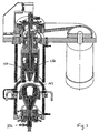
- Figure 2 depicts the centrifuge of Fig. 1 in a feed mode of operation.
- the lower and middle portions of the separator housing are cooled by the flow of cooling liquid 113.
- Lower and upper lip seals, as well as the lower bearing assembly, are cooled by coolant flow 179.
- Rotation (152) of the separator bowl is caused by the drive motor at a speed sufficient to achieve an appropriate level of centrifugal force within the bowl as required for the desired separation.
- the lower three-way ball valve 175 is set to open a pathway from feed liquid port 172 to inlet port 170.
- the upper three-way ball valve 185 is set to open a pathway from centrate port 183 to outlet port 180. Feed liquid 171 is pumped into the bowl from below.
- centrate liquid As feed liquid enters the bowl cavity, solids are deposited onto the inner wall of the bowl liner, and clarified centrate fluid accumulates around the bowl's central axis.
- the centrate liquid flows into the second fluid pathway 214 of the piston.
- the rate of flow is sufficient to cause shuttle valve 250 to open, allowing the flow of centrate liquid 183 up through the piston and out through centrate port 182.
- the rate of flow is not so high as to cause the shuttle valve to seal at its upper surface, which would block flow through first fluid pathway 212.
- the feed mode can continue until sufficient solids have accumulated inside the bowl to justify or require draining the bowl and running a solids discharge cycle.
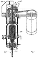
- Figure 3 depicts the centrifuge of Fig. 1 in a drain mode.
- the drive motor and bowl 150 have braked to a stop.
- Residual feed liquid 371 is drained or pumped back through the feed liquid port, and can be collected or recycled back to a feed liquid holding tank.
- shuttle valve 250 closes to prevent backflow of centrate through the first fluid pathway of the piston and into the bowl chamber.
- the collected solids 173 remain adhered to the bowl liner.
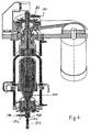
- FIG. 4 shows the centrifuge of Fig. 1 just after draining as shown in Fig. 3 .
- the centrifuge is shown in a centrate purge mode.
- An inert drive gas 190 e.g., air, nitrogen, or argon
- the flow rate of the gas is sufficient to open the shuttle valve from the second fluid pathway, but not sufficient to close the shuttle valve to the first fluid pathway.
- Centrate liquid 183 remaining from the drain cycle is driven out the centrate port 182 by the drive gas.
- FIG. 5 depicts the centrifugal separator of Fig. 1 in a solids discharge mode.
- Lower three-way ball valve 175 has been switched to provide a pathway from the inlet port to solids discharge port 174.
- Upper three-way ball valve 185 has been switched to provide a pathway from the outlet port to both centrate port 182 and optical port 184, which contains a window for transmitting laser beam 282 in both directions.
- Drive gas 190 is introduced through centrate port 182, causing the shuttle valve 250 to close at its lower surface, preventing flow of the gas through the second fluid pathway in the piston. The pressure of the drive gas causes the piston to move downward in the bowl, displacing the accumulated solids from the inner face of the bowl liner and out through the solids discharge valve for collection.
- the motion of the piston is tracked by the laser beam, which is reflected off the mirror on the shuttle valve back into a signal processing unit attached to the separator housing. Because the solids consistency may vary, the time required to complete solids discharge may also vary.
- the use of an automated piston position sensing system allows the piston position within the bowl to be known, so that the cycle can be terminated by stopping the flow of drive gas at the appropriate time, e.g., when the piston has reached the bottom of the bowl.
- FIG. 7 the separator of Fig. 1 is shown in a piston retraction mode. Following a solids discharge cycle, the piston is returned to its uppermost position prior to beginning another feed cycle. Lower three-way valve 175 has been switched to connect only the feed liquid port 172 to the inlet port. Drive gas 190 is applied through feed liquid port 172 to urge the piston upward. The gas pressure is sufficient to close the shuttle valve against the first fluid pathway in the piston. The supply of drive gas at centrate port 182 has been cut off, but the valve remains open to permit gas to escape as the piston rises. Laser 280 is used to track the movement of the piston, sensing when the piston has reached the top of its stroke.
- FIG. 8 schematically depicts how disposable elements of the separator are removed and replaced.
- Upper valve and seal assembly 230 and lower valve and seal assembly 232 are removed and discarded.
- the lower portion of the separator housing is removed, and then the feed cone nut is unscrewed and the feed cone and lower bearing assembly is removed; these components are set aside for reuse.
- Bowl liner 220 containing piston 200 with shuttle valve 250 are removed and discarded.
- a new bowl liner assembly containing a new piston and shuttle valve can then be installed in the housing.
- the feed cone and lower bearing assembly is replaced and retained using the feed cone lock nut.
- the lower housing portion is replaced, and new upper and lower valve and seal assemblies are installed.
- the separator is then prepared to separate a new sample.
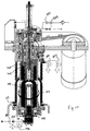
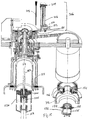
- Figure 9 shows another embodiment of a centrifugal separator according to the invention having dual solids discharge pistons.
- the separator is shown in vertical section with a middle section removed. Many of the parts are the same as, or similar to, the embodiment depicted in Fig. 1 . The differences are discussed below.
- the dual piston design allows for more complete extraction of solids, and also less cross-contamination between cycles, than a single piston design.
- Separator bowl 150 encases bowl liner 220, which is removable from the bowl and preferably disposable.
- First piston 200 which is responsible for discharging most of the solids accumulated along the inner wall of the bowl liner, is encased by the liner, and the sides of the piston conform to the inner wall of the bowl liner.
- central core 225 Aligned with the central vertical axis of the bowl liner is central core 225, which extends from the top to the bottom of the bowl liner.
- the lower inner surface of the bowl liner preferably conforms to the lower surface of the first piston.
- the first piston includes a central hole to accommodate the central core, along which the first piston moves within the bowl liner.
- second piston 205 which is attached at its top surface to pushrod 208, used to drive the second piston downward to expel residual solids during the discharge cycle.
- the second piston can be configured in different diameters, according to the needs of the separation.
- Fig. 9A depicts a large second piston design, appropriate for a thicker, more viscous solid paste
- Fig. 9C depicts a small second piston design with smaller piston diameter, suitable for thinner, less viscous solid paste.
- the large configuration of the second piston preferably has a diameter from about 30 to about 40 mm
- the small configuration preferably has a diameter from about 10 mm to about 30 mm, though other sizes also can be used according to the needs of a particular application.
- Cylindrical extension 154 extends from the bottom of the bowl liner and forms the pathway for both adding feed liquid to the separator during separation and removing accumulated solids during the solids discharge process.
- seals can be "Flexlip” all plastic lip seals (Parker, Cleveland, Ohio), and the sleeve can be a CR “Speedi Sleeve®” (SKF Sealing Solutions, Elgin, Illinois).
- Ports 188 for seal cooling liquid can be included in the centrate valve assembly, as well as a seal leakage drain port 189.
- Feed/discharge valve assembly 175 is attached to the lower end of lower bearing assembly 121, and includes a three-way valve to allow switching between one pathway providing access to feed liquid and another pathway providing an exit port for solids discharge from the separator.
- the solids discharge path through the valve has a diameter that just accommodates the second piston, which is extended through the valve to remove the last remaining residual solids from the valve during a final discharge operation.
- the three-way valve can be, for example, a ball valve.
- the feed/discharge assembly can be configured in large and small versions, for use with the large and small embodiments of the second piston, as described above.
- the feed/discharge valve assembly is disposable, and preferably made of one or more plastic materials.
- Figure 10 shows the separator of Fig. 9 in a feed and separation mode.
- the first and second pistons are in their uppermost positions.
- the bowl is rotated 152 at a speed appropriate for separation.
- Drive motor 300 is preferably a variable speed vector-type motor with speed and angular position sensing.
- cooling liquid 113 is circulated through the separator housing. Solids 173 accumulate along the inner wall of the bowl liner. The presence of the central core eliminates most of the air space within the bowl, thereby eliminating a source of turbulence that can be detrimental to both the separation and to components of the feed liquid that are being separated.
- Second piston push rod 308 includes one or more openings just above its contact point with the second piston; these openings allow centrate fluid to escape upwards through the hollow push rod 308. Cooling liquid is circulated through seal cooling ports 178 and 188.
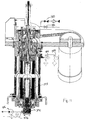
- Figure 12 shows the separator of Fig. 9 in an initial solids discharge mode following the drain mode.
- the drive motor is stopped.
- Feed/discharge valve 175 is rotated to the discharge position, and accumulated solids 373 are discharged through the discharge port.
- Feed retract valve 376 is closed, and feed pump 372 is off.
- Drive gas 190 is applied through solids discharge valve 374.
- a solids discharge piston air supply isolation actuator 201 is urged downward by drive gas applied to isolation actuator port 202. In this position, the isolation actuator opens a pathway from first piston down port 204 to allow drive gas from the discharge valve to reach the space above first piston 200, thereby urging the piston downward. Valves 375, 376, 382, and 383 remain closed.
- the position of the first piston within the bowl can be tracked using time-of-flight laser unit 280, which sends laser beam 282 through the upper bearing assembly and a window in the bowl and bowl liner to be reflected off a mirrored surface or reflective tape 260 on the top surface of the first piston.
- Figure 13 shows the separator of Fig. 9 in a final discharge mode following the initial discharge mode shown in Fig. 12 .
- the drive motor is stopped.
- the first piston 200 is lowered all the way to the bottom of the bowl, and second piston 205 is lowered through the feed/discharge valve to remove the last remaining solids 373 from the valve.
- the second piston is driven downward through the action of hollow push rod 208, which in turn is driven by second piston actuator 206.
- the actuator is driven by gas applied to second piston down port 209.
- Second piston actuator drive rod 208 contacts second piston push rod 308.
- Push rod 308 Discharge valve 374 remains open and the first piston isolation actuator remains in the down position with gas applied at ports 202 and 204, which maintains the first piston in its lowermost position.
- the position of the second piston within the bowl or discharge valve can be tracked using second piston position sensor 207, which can be, e.g., a magnetic or capacitive position sensor within actuator 206.
- second piston position sensor 207 can be, e.g., a magnetic or capacitive position sensor within actuator 206.
- Remaining valves 376, 375, 382, and 383 are closed.
- Figure 14 shows the separator of Fig. 9 in a piston retract mode following the final discharge mode shown in Fig. 13 .
- the drive motor is stopped.
- Retract valve 376 is open and in feed position, and drive gas is applied through the feed/discharge valve to raise the first piston.
- Gas is also applied to piston isolation actuator down port 202 to maintain isolation actuator 201 in the lowered position, which opens a pathway to allow drive gas from port 203 to reach the underside of the second piston.
- the drive gas drives the second piston upward to its starting position, and the second piston in turn drives push rod 308 upwards as well, to its starting position within the separator bowl spindle.
- Drive gas is also applied to second piston actuator up port 210 to retract second piston drive rod 208.
- Piston vent valve 375 is open to allow gas trapped above the first piston to escape through port 204; this is also enabled by the lowered position of the isolation activator, which opens a pathway between port 204 and the space above the first piston. Valves 374, 382, and 383 are closed. The positions of the first and second pistons can be monitored during retraction using their respective position sensing systems. Once the first piston has been fully retracted, the isolation actuator is also retracted to the raised position by applying drive gas to isolation activator up port 302.
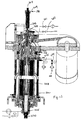
- FIG. 15 shows the separator of Fig. 9 disassembled for replacement of disposable parts between runs.
- Displacement transducer 207 is removed for reuse or replacement from the disposable centrate valve/second piston actuator assembly 306, which is replaced by a fresh, preferably sterile assembly.
- feed/discharge valve assembly 232 is removed and replaced with a new, preferably sterile assembly.
- lower housing claim ring 112 and lower housing cap 312 are first removed. Then, once the bowl is locked in place by tightening lock handles 124, the lower bearing assembly 121 and bowl bottom lock nut 156 can be removed. This exposes the assembly containing bowl liner 200, first piston 200, central core 225, lower liner extension 153, and upper liner extension 353. The assembly is removed and replaced by a new, preferably sterilized assembly.
- kits containing any combination of the disposable elements or assemblies used in a dual piston centrifugal separator according to the invention can contain any of the following, or any combination thereof: a disposable bowl liner, a disposable bowl liner/first piston assembly, a disposable separator bowl/bowl liner/first piston assembly, a disposable centrate valve assembly, a disposable second piston assembly, a disposable centrate valve/second piston assembly, or a disposable feed/discharge valve assembly.
- kits may also include instructions for installation and/or use of the provided disposable components in the separator.
- step (a) feed liquid is flowed or pumped into the separator bowl through an inlet port.
- the separator bowl contains a hollow central core, a first piston surrounding the core, and a second piston within the core.
- step (b) the separator bowl is rotated through the action of a drive motor, and in the process, solid or denser components of the feed liquid accumulate on the inner surface of the bowl or bowl liner.
- step (c) the separator bowl is continued to be rotated while feed liquid flows into the inlet port, resulting in the production of a clarified centrate liquid that flows out through an outlet port.
- step (d) bowl rotation is stopped, and residual liquid is drained from the bowl through the inlet port.
- a pressurized fluid such as a drive gas, is introduced into the bowl, causing the first piston to be displaced downward within the bowl, and causing accumulated solids to be discharged through the inlet port.
- step (f) an actuator for the second piston is driven downward, causing the second piston to move downward within the central core, and causing residual solids to be discharged through the inlet port.
- step (g) a pressurized fluid or drive gas is introduced through the inlet port into the bowl, forcing the first piston to be displaced upward in the bowl, recreating the starting conditions for step (a).
- steps (a) through (g) are repeated for two or more cycles, which can be useful to process large amounts of a single feed liquid material, for example.
- step (h) the separator is partially disassembled following step (f) or step (g), and one or more disposable components of the separator are replaced prior to repeating step (a). This is useful when switching the feed material to a different material, avoids cross-contamination between different types of feed material, and also helps to maintain sterility.
- fluid pressure may be replaced in other embodiments by, without limitation, an electromechanical force.
- the lower portion and end of the piston and bowl, respectively may be non-conical in shape, although it is preferable for solids recovery that their shapes be complimentary.
- Valves can be operated manually or by, e.g., electrically or pressure-driven actuators.
- the invention also contemplates that the various passages, valves, pistons, actuators, assemblies, ports, members and the like described herein can be in any configuration or arrangement that would be suitable for operation of a centrifugal separator.
- the embodiments described above may also each include or incorporate any of the variations of all other embodiments.
- the laser piston position sensor assembly described herein can be used in conjunction with any or all of the embodiments of the present invention.
- the centrifugal separator can be hermetically sealed or can lack hermetic seals.
- Various components e.g., bowls, bowl liners, pistons, or valves, can be provided as separate items or combined with related items as a kit, including instructions for use with a separator or a method according to the invention.
- the embodiments described herein may also include any of the components or configurations described in any of U.S. Published Patent Application Nos. 2007-0049479 and 2007-0114161 , U.S. Patent 7,261,683 , U.S. Patent 7,052,451 , and U.S. Patent 6,986,734 . It is therefore intended that the protection granted by Letter Patent hereon be limited only by the definitions contained in the appended claims.
Landscapes
- Centrifugal Separators (AREA)
- Cyclones (AREA)
Applications Claiming Priority (2)
| Application Number | Priority Date | Filing Date | Title |
|---|---|---|---|
| US14104008P | 2008-12-29 | 2008-12-29 | |
| PCT/IB2009/007990 WO2010076657A2 (en) | 2008-12-29 | 2009-12-29 | Solids discharge centrifugal separator with disposable contact elements |
Publications (2)
| Publication Number | Publication Date |
|---|---|
| EP2389253A2 EP2389253A2 (en) | 2011-11-30 |
| EP2389253B1 true EP2389253B1 (en) | 2016-03-30 |
Family
ID=42244192
Family Applications (1)
| Application Number | Title | Priority Date | Filing Date |
|---|---|---|---|
| EP09810788.1A Not-in-force EP2389253B1 (en) | 2008-12-29 | 2009-12-29 | Solids discharge centrifugal separator with disposable contact elements |
Country Status (6)
| Country | Link |
|---|---|
| US (1) | US8475352B2 (enExample) |
| EP (1) | EP2389253B1 (enExample) |
| JP (1) | JP5688374B2 (enExample) |
| CN (1) | CN102387867B (enExample) |
| AU (1) | AU2009334385B2 (enExample) |
| WO (1) | WO2010076657A2 (enExample) |
Cited By (1)
| Publication number | Priority date | Publication date | Assignee | Title |
|---|---|---|---|---|
| WO2019008121A1 (en) | 2017-07-06 | 2019-01-10 | Riera Nadeu, Sa | SUPERCENTRIFUGE WITH AUTOMATIC EVACUATION OF SOLID PARTICLES |
Families Citing this family (12)
| Publication number | Priority date | Publication date | Assignee | Title |
|---|---|---|---|---|
| US7618361B2 (en) * | 2005-09-01 | 2009-11-17 | Wagner Development, Inc. | Gas driven solids discharge and pumping piston for a centrifugal separator |
| AU2009334385B2 (en) * | 2008-12-29 | 2015-10-08 | Wagner Development, Inc. | Solids discharge centrifugal separator with disposable contact elements |
| DE102012105499A1 (de) * | 2012-06-25 | 2014-01-02 | Gea Mechanical Equipment Gmbh | Separator |
| ES2424272B1 (es) * | 2013-07-23 | 2014-01-29 | Riera Nadeu, S.A. | Supercentrífuga con dispositivo no intrusivo de extracción de sólido y procedimiento de extracción del mismo |
| EP3148701B2 (de) | 2014-05-28 | 2025-08-27 | GEA Mechanical Equipment GmbH | Separator |
| US9656287B2 (en) * | 2015-05-21 | 2017-05-23 | Nordson Corporation | Handheld valve dispensers and related methods |
| CN104907188A (zh) * | 2015-06-30 | 2015-09-16 | 江苏泰仓农化有限公司 | 一种苯菌灵生产用离心机排出系统 |
| US10449555B2 (en) * | 2017-05-16 | 2019-10-22 | Robert Bret Carr | Centrifugal separator with annular piston for solids extrusion |
| KR102051207B1 (ko) * | 2018-01-30 | 2019-12-03 | 이준석 | 원심분리용 피스톤 |
| EP3801920A4 (en) * | 2018-06-08 | 2022-07-13 | Pneumatic Scale Corporation | Centrifuge system for separating cells in suspension |
| CN110639711A (zh) * | 2019-10-12 | 2020-01-03 | 陈春友 | 一种生物无菌离心续接分选生物反应器 |
| CN115646667B (zh) * | 2022-11-03 | 2023-10-27 | 宜兴市华鼎机械有限公司 | 一种两相全密闭防爆卧式离心机 |
Family Cites Families (66)
| Publication number | Priority date | Publication date | Assignee | Title |
|---|---|---|---|---|
| US1909188A (en) * | 1931-04-15 | 1933-05-16 | Western States Machine Co | Apparatus for discharging centrifugal machines |
| US2040351A (en) * | 1932-11-23 | 1936-05-12 | Frank I Williams | Centrifugal machine |
| GB400809A (en) * | 1933-01-18 | 1933-11-02 | Aage Nyrop | Improvements in centrifugal separators |
| US2094058A (en) * | 1934-11-03 | 1937-09-28 | American Machine & Metals | Aperiodic mounting for centrifugal separators |
| US3239136A (en) * | 1962-05-07 | 1966-03-08 | George N Hein | Centrifuge and centrifuge head for separating constituents of a liquid and a liner therefor |
| US3306681A (en) * | 1964-08-07 | 1967-02-28 | Hubert P Barringer | Damped bearing for centrifuges |
| US3403848A (en) * | 1967-04-03 | 1968-10-01 | Star Cutter Company | Centrifugal separator apparatus |
| US3539096A (en) * | 1967-04-27 | 1970-11-10 | Dow Oliver Inc | Hy-g centrifuge |
| US3741465A (en) * | 1971-01-20 | 1973-06-26 | Star Cutter Co | Centrifugal separator with internal scraper blades |
| US3770191A (en) * | 1971-06-28 | 1973-11-06 | Sorvall Inc Ivan | Means for stabilizing high speed rotors |
| SE370501B (enExample) * | 1973-02-13 | 1974-10-21 | Pellerin Ab Zenith | |
| US3972514A (en) * | 1975-07-02 | 1976-08-03 | Voitsekhovsky Bogdan Vyachesla | Centrifuge for the refining of nonferrous metals |
| CH604906A5 (en) | 1977-03-16 | 1978-09-15 | Werner K Dorner | Centrifugal impeller with open frame blades |
| SU772567A2 (ru) * | 1977-03-23 | 1980-10-23 | Севастопольский Приборостроительный Институт | Устройство дл очистки воды от нефтепродуктов |
| EP0056511A3 (en) * | 1981-01-19 | 1984-07-11 | The Chartwell House Group Limited | Improved centrifuge and method of cleaning a centrifuge drum |
| CS238202B1 (en) * | 1982-05-31 | 1985-11-13 | Zdenek Rajsigl | High-speed rotor resilient mounting |
| FR2530489B1 (fr) * | 1982-07-26 | 1987-02-27 | Pro Catalyse | Procede de fabrication de catalyseurs pour le traitement des gaz d'echappement des moteurs a combustion interne |
| CH656326A5 (de) * | 1982-09-06 | 1986-06-30 | Escher Wyss Ag | Doppel-schubzentrifuge mit einer rotierbaren schubeinrichtung. |
| IL74527A0 (en) * | 1985-03-07 | 1985-06-30 | Amiad Sinon Vehashkaya | Fluid filtering device |
| FR2583993B1 (fr) * | 1985-07-01 | 1990-08-24 | Cogema | Decanteuse centrifuge du type pendulaire |
| DE3533306A1 (de) | 1985-09-18 | 1987-03-26 | Adolf Reiter | Verfahren zur auftrennung und klarfiltration von suspensionen und vorrichtung zu seiner durchfuehrung |
| JPS63171656A (ja) | 1986-12-30 | 1988-07-15 | Hasegawa Etsuko | 液体遠心脱水装置 |
| CS266602B1 (en) * | 1987-11-19 | 1990-01-12 | Rajsigl Zdenek | Rolling seating for a textile spindle |
| JPH01218602A (ja) * | 1988-02-25 | 1989-08-31 | Nitto Denko Corp | 微粒子含有液体の分離処理方法 |
| US5328441A (en) * | 1991-12-04 | 1994-07-12 | Carr Engineering Associates, Inc. | Imperforate bowl centrifugal separator with solids gate |
| US5356367A (en) * | 1991-12-04 | 1994-10-18 | Carr Engineering Associates, Inc. | Centrifugal separator with flexibly suspended restrainable bowl |
| US5250180A (en) * | 1992-11-10 | 1993-10-05 | Fwu Kuang Enterprises Co., Ltd. | Oil recovering apparatus from used lubricant |
| JPH07144150A (ja) | 1993-04-13 | 1995-06-06 | N S P:Kk | 液体分離装置 |
| US5364335A (en) * | 1993-12-07 | 1994-11-15 | Dorr-Oliver Incorporated | Disc-decanter centrifuge |
| US5454777A (en) * | 1994-10-05 | 1995-10-03 | Glassline Corporation | Centrifugal separator apparatus with load sensing circuit for optimizing clearing cycle frequency |
| JP3375014B2 (ja) | 1994-11-15 | 2003-02-10 | トリニティ工業株式会社 | スラッジ回収装置 |
| JP3522884B2 (ja) | 1995-03-31 | 2004-04-26 | トリニティ工業株式会社 | スラッジ回収装置 |
| JP2954862B2 (ja) | 1995-09-21 | 1999-09-27 | 住友建機株式会社 | 小物部品の洗浄方法及び洗浄装置 |
| US5733238A (en) * | 1995-10-24 | 1998-03-31 | Carr Separations, Inc. | Scraping assembly having angularly offset scraper blades for removing solids from an imperforate bowl centrifuge |
| US5674174A (en) | 1995-11-01 | 1997-10-07 | Carr Separations, Inc. | Low-shear feeding system for use with bottom feed centrifuges |
| US5823937A (en) * | 1995-11-01 | 1998-10-20 | Carr; Robert B. | Low-shear feeding system for use with centrifuges |
| US6123655A (en) * | 1996-04-24 | 2000-09-26 | Fell; Claude | Cell separation system with variable size chamber for the processing of biological fluids |
| US5743840A (en) * | 1996-06-24 | 1998-04-28 | Carr Separations, Inc. | Centrifuge with a heating jacket for drying collected solids |
| US5879279A (en) * | 1996-09-05 | 1999-03-09 | U.S. Centrifuge | Centrifugal separator apparatus having a vibration sensor |
| EP0951360A4 (en) * | 1997-01-08 | 2003-08-27 | Bristol Myers Squibb Co | BLOOD SEPARATION CENTRIFUGE |
| US6126587A (en) * | 1998-04-08 | 2000-10-03 | U.S. Centrifuge | Centrifugal separator apparatus including a plow blade assembly |
| US6478724B1 (en) * | 1998-06-03 | 2002-11-12 | Jeffery N. Beattey | Centrifuge with clutch mechanism for synchronous blade and bowl rotation |
| US6224532B1 (en) * | 1998-06-03 | 2001-05-01 | Jeffery N. Beattey | Centrifuge blade design and control mechanism |
| US5916082A (en) * | 1998-08-12 | 1999-06-29 | Glassline Corporation | Centrifugal separator with invertable bladder |
| PT1144026E (pt) | 1998-12-24 | 2004-12-31 | Biosafe Sa | Sistema para separacao sanguinea util, em particular, para concentracoes de celulas estaminais hematopoieticas |
| EP1028163A1 (de) | 1999-02-10 | 2000-08-16 | Filtrox AG | Verfahren und Vorrichtung zur Crossflow-Mikrofiltration einer Flüssigkeit |
| US6244256B1 (en) | 1999-10-07 | 2001-06-12 | Behr Gmbh & Co. | High-temperature coolant loop for cooled exhaust gas recirculation for internal combustion engines |
| US6613232B2 (en) * | 2000-03-21 | 2003-09-02 | Warren Howard Chesner | Mobile floating water treatment vessel |
| WO2001089706A1 (en) * | 2000-05-19 | 2001-11-29 | Kendro Laboratory Products, L.P. | Low-shear feeding system for use with centrifuges |
| US6387030B1 (en) * | 2000-06-30 | 2002-05-14 | Beckman Coulter, Inc. | Internal adapter with a pellet well for a centrifuge container |
| US6632166B2 (en) * | 2000-08-04 | 2003-10-14 | Robert B. Carr | Centrifuge having axially movable scraping assembly for automatic removal of solids |
| US20030127391A1 (en) * | 2001-07-26 | 2003-07-10 | Craft Frank S. | Method for treatment of circulating cooling water |
| JP2003144973A (ja) | 2001-11-09 | 2003-05-20 | Horyo Corp | 遠心分離装置 |
| CN100435969C (zh) * | 2002-04-12 | 2008-11-26 | 瓦格纳发展公司 | 具有刮削器或活塞的用于卸出固体的离心机 |
| US6800053B2 (en) * | 2002-12-23 | 2004-10-05 | Kendro Laboratory Products, Lp | Method and apparatus for sterilizing internal passages of a centrifuge centrate gate |
| PT1503032E (pt) * | 2003-07-28 | 2006-05-31 | Herrenknecht Ag | Dispositivo para a captacao do estado de rotacao dos rolos de corte de uma maquina tuneladora de escudo |
| US20050023883A1 (en) * | 2003-08-01 | 2005-02-03 | Shimano Inc. | Bicycle rim |
| US6997860B2 (en) * | 2003-08-18 | 2006-02-14 | Glassline Corporation | Single drive centrifugal separator |
| US7052451B2 (en) * | 2004-04-14 | 2006-05-30 | Wagner Development, Inc. | Conical piston solids discharge centrifugal separator |
| US7261683B2 (en) * | 2004-04-14 | 2007-08-28 | Wagner Development, Inc. | Conical piston solids discharge and pumping centrifugal separator |
| US7261783B1 (en) * | 2004-09-22 | 2007-08-28 | The United States Of America As Represented By The Administrator Of Nasa | Low density, high creep resistant single crystal superalloy for turbine airfoils |
| US7628749B2 (en) | 2005-09-01 | 2009-12-08 | Wagner Development Inc. | Solids recovery using cross-flow microfilter and automatic piston discharge centrifuge |
| US7618361B2 (en) * | 2005-09-01 | 2009-11-17 | Wagner Development, Inc. | Gas driven solids discharge and pumping piston for a centrifugal separator |
| WO2007135481A2 (en) * | 2005-12-05 | 2007-11-29 | Wagner Development, Inc. | Solids recovery using cross-flow microfilter and automatic piston discharge centrifuge |
| JP2008012375A (ja) * | 2006-07-03 | 2008-01-24 | Nittetsu Mining Co Ltd | 遠心脱液装置 |
| AU2009334385B2 (en) * | 2008-12-29 | 2015-10-08 | Wagner Development, Inc. | Solids discharge centrifugal separator with disposable contact elements |
-
2009
- 2009-12-29 AU AU2009334385A patent/AU2009334385B2/en not_active Ceased
- 2009-12-29 WO PCT/IB2009/007990 patent/WO2010076657A2/en not_active Ceased
- 2009-12-29 EP EP09810788.1A patent/EP2389253B1/en not_active Not-in-force
- 2009-12-29 US US12/648,625 patent/US8475352B2/en not_active Expired - Fee Related
- 2009-12-29 CN CN2009801576701A patent/CN102387867B/zh not_active Expired - Fee Related
- 2009-12-29 JP JP2011542924A patent/JP5688374B2/ja not_active Expired - Fee Related
Cited By (1)
| Publication number | Priority date | Publication date | Assignee | Title |
|---|---|---|---|---|
| WO2019008121A1 (en) | 2017-07-06 | 2019-01-10 | Riera Nadeu, Sa | SUPERCENTRIFUGE WITH AUTOMATIC EVACUATION OF SOLID PARTICLES |
Also Published As
| Publication number | Publication date |
|---|---|
| WO2010076657A2 (en) | 2010-07-08 |
| JP2012513888A (ja) | 2012-06-21 |
| CN102387867A (zh) | 2012-03-21 |
| AU2009334385A1 (en) | 2011-07-21 |
| US20100167899A1 (en) | 2010-07-01 |
| US8475352B2 (en) | 2013-07-02 |
| AU2009334385B2 (en) | 2015-10-08 |
| CN102387867B (zh) | 2013-12-11 |
| WO2010076657A3 (en) | 2011-03-24 |
| JP5688374B2 (ja) | 2015-03-25 |
| EP2389253A2 (en) | 2011-11-30 |
Similar Documents
| Publication | Publication Date | Title |
|---|---|---|
| EP2389253B1 (en) | Solids discharge centrifugal separator with disposable contact elements | |
| US7935042B2 (en) | Gas driven solids discharge and pumping piston for a centrifugal separator | |
| KR101466923B1 (ko) | 재생성 세포 추출장치, 재생성 세포 추출 시스템, 이를 이용한 재생성 세포 추출방법 | |
| US6776752B2 (en) | Automatic tube bowl centrifuge for centrifugal separation of liquids and solids with solids discharge using a scraper or piston | |
| NO314715B1 (no) | Apparat og fremgangsmate for separering av en vaeskeprove | |
| JP2012513888A5 (enExample) | ||
| US7628749B2 (en) | Solids recovery using cross-flow microfilter and automatic piston discharge centrifuge | |
| US10449555B2 (en) | Centrifugal separator with annular piston for solids extrusion | |
| US11135599B2 (en) | Two zone disposable process contact centrifuge for bio-separations | |
| AU2006343994A1 (en) | Solids recovery using cross-flow microfilter and automatic piston discharge centrifuge | |
| US7261683B2 (en) | Conical piston solids discharge and pumping centrifugal separator | |
| KR101544076B1 (ko) | 원심분리기 | |
| KR101707474B1 (ko) | 통합밸브유닛과 이를 이용한 유핵세포추출장치 | |
| US20160175853A1 (en) | Centrifuge Feed Accelerator with Feed Vanes |
Legal Events
| Date | Code | Title | Description |
|---|---|---|---|
| PUAI | Public reference made under article 153(3) epc to a published international application that has entered the european phase |
Free format text: ORIGINAL CODE: 0009012 |
|
| 17P | Request for examination filed |
Effective date: 20110713 |
|
| AK | Designated contracting states |
Kind code of ref document: A2 Designated state(s): AT BE BG CH CY CZ DE DK EE ES FI FR GB GR HR HU IE IS IT LI LT LU LV MC MK MT NL NO PL PT RO SE SI SK SM TR |
|
| DAX | Request for extension of the european patent (deleted) | ||
| 17Q | First examination report despatched |
Effective date: 20150701 |
|
| GRAP | Despatch of communication of intention to grant a patent |
Free format text: ORIGINAL CODE: EPIDOSNIGR1 |
|
| INTG | Intention to grant announced |
Effective date: 20151006 |
|
| GRAS | Grant fee paid |
Free format text: ORIGINAL CODE: EPIDOSNIGR3 |
|
| GRAA | (expected) grant |
Free format text: ORIGINAL CODE: 0009210 |
|
| AK | Designated contracting states |
Kind code of ref document: B1 Designated state(s): AT BE BG CH CY CZ DE DK EE ES FI FR GB GR HR HU IE IS IT LI LT LU LV MC MK MT NL NO PL PT RO SE SI SK SM TR |
|
| REG | Reference to a national code |
Ref country code: GB Ref legal event code: FG4D |
|
| REG | Reference to a national code |
Ref country code: CH Ref legal event code: EP |
|
| REG | Reference to a national code |
Ref country code: AT Ref legal event code: REF Ref document number: 784774 Country of ref document: AT Kind code of ref document: T Effective date: 20160415 |
|
| REG | Reference to a national code |
Ref country code: IE Ref legal event code: FG4D |
|
| REG | Reference to a national code |
Ref country code: DE Ref legal event code: R096 Ref document number: 602009037388 Country of ref document: DE |
|
| REG | Reference to a national code |
Ref country code: LT Ref legal event code: MG4D |
|
| PG25 | Lapsed in a contracting state [announced via postgrant information from national office to epo] |
Ref country code: FI Free format text: LAPSE BECAUSE OF FAILURE TO SUBMIT A TRANSLATION OF THE DESCRIPTION OR TO PAY THE FEE WITHIN THE PRESCRIBED TIME-LIMIT Effective date: 20160330 Ref country code: GR Free format text: LAPSE BECAUSE OF FAILURE TO SUBMIT A TRANSLATION OF THE DESCRIPTION OR TO PAY THE FEE WITHIN THE PRESCRIBED TIME-LIMIT Effective date: 20160701 Ref country code: NO Free format text: LAPSE BECAUSE OF FAILURE TO SUBMIT A TRANSLATION OF THE DESCRIPTION OR TO PAY THE FEE WITHIN THE PRESCRIBED TIME-LIMIT Effective date: 20160630 Ref country code: HR Free format text: LAPSE BECAUSE OF FAILURE TO SUBMIT A TRANSLATION OF THE DESCRIPTION OR TO PAY THE FEE WITHIN THE PRESCRIBED TIME-LIMIT Effective date: 20160330 |
|
| REG | Reference to a national code |
Ref country code: NL Ref legal event code: MP Effective date: 20160330 |
|
| REG | Reference to a national code |
Ref country code: AT Ref legal event code: MK05 Ref document number: 784774 Country of ref document: AT Kind code of ref document: T Effective date: 20160330 |
|
| PG25 | Lapsed in a contracting state [announced via postgrant information from national office to epo] |
Ref country code: SE Free format text: LAPSE BECAUSE OF FAILURE TO SUBMIT A TRANSLATION OF THE DESCRIPTION OR TO PAY THE FEE WITHIN THE PRESCRIBED TIME-LIMIT Effective date: 20160330 Ref country code: LT Free format text: LAPSE BECAUSE OF FAILURE TO SUBMIT A TRANSLATION OF THE DESCRIPTION OR TO PAY THE FEE WITHIN THE PRESCRIBED TIME-LIMIT Effective date: 20160330 Ref country code: LV Free format text: LAPSE BECAUSE OF FAILURE TO SUBMIT A TRANSLATION OF THE DESCRIPTION OR TO PAY THE FEE WITHIN THE PRESCRIBED TIME-LIMIT Effective date: 20160330 |
|
| PG25 | Lapsed in a contracting state [announced via postgrant information from national office to epo] |
Ref country code: NL Free format text: LAPSE BECAUSE OF FAILURE TO SUBMIT A TRANSLATION OF THE DESCRIPTION OR TO PAY THE FEE WITHIN THE PRESCRIBED TIME-LIMIT Effective date: 20160330 |
|
| PG25 | Lapsed in a contracting state [announced via postgrant information from national office to epo] |
Ref country code: PL Free format text: LAPSE BECAUSE OF FAILURE TO SUBMIT A TRANSLATION OF THE DESCRIPTION OR TO PAY THE FEE WITHIN THE PRESCRIBED TIME-LIMIT Effective date: 20160330 Ref country code: IS Free format text: LAPSE BECAUSE OF FAILURE TO SUBMIT A TRANSLATION OF THE DESCRIPTION OR TO PAY THE FEE WITHIN THE PRESCRIBED TIME-LIMIT Effective date: 20160730 Ref country code: EE Free format text: LAPSE BECAUSE OF FAILURE TO SUBMIT A TRANSLATION OF THE DESCRIPTION OR TO PAY THE FEE WITHIN THE PRESCRIBED TIME-LIMIT Effective date: 20160330 |
|
| REG | Reference to a national code |
Ref country code: DE Ref legal event code: R082 Ref document number: 602009037388 Country of ref document: DE |
|
| PG25 | Lapsed in a contracting state [announced via postgrant information from national office to epo] |
Ref country code: ES Free format text: LAPSE BECAUSE OF FAILURE TO SUBMIT A TRANSLATION OF THE DESCRIPTION OR TO PAY THE FEE WITHIN THE PRESCRIBED TIME-LIMIT Effective date: 20160330 Ref country code: PT Free format text: LAPSE BECAUSE OF FAILURE TO SUBMIT A TRANSLATION OF THE DESCRIPTION OR TO PAY THE FEE WITHIN THE PRESCRIBED TIME-LIMIT Effective date: 20160801 Ref country code: RO Free format text: LAPSE BECAUSE OF FAILURE TO SUBMIT A TRANSLATION OF THE DESCRIPTION OR TO PAY THE FEE WITHIN THE PRESCRIBED TIME-LIMIT Effective date: 20160330 Ref country code: SK Free format text: LAPSE BECAUSE OF FAILURE TO SUBMIT A TRANSLATION OF THE DESCRIPTION OR TO PAY THE FEE WITHIN THE PRESCRIBED TIME-LIMIT Effective date: 20160330 Ref country code: CZ Free format text: LAPSE BECAUSE OF FAILURE TO SUBMIT A TRANSLATION OF THE DESCRIPTION OR TO PAY THE FEE WITHIN THE PRESCRIBED TIME-LIMIT Effective date: 20160330 Ref country code: SM Free format text: LAPSE BECAUSE OF FAILURE TO SUBMIT A TRANSLATION OF THE DESCRIPTION OR TO PAY THE FEE WITHIN THE PRESCRIBED TIME-LIMIT Effective date: 20160330 Ref country code: AT Free format text: LAPSE BECAUSE OF FAILURE TO SUBMIT A TRANSLATION OF THE DESCRIPTION OR TO PAY THE FEE WITHIN THE PRESCRIBED TIME-LIMIT Effective date: 20160330 |
|
| PG25 | Lapsed in a contracting state [announced via postgrant information from national office to epo] |
Ref country code: IT Free format text: LAPSE BECAUSE OF FAILURE TO SUBMIT A TRANSLATION OF THE DESCRIPTION OR TO PAY THE FEE WITHIN THE PRESCRIBED TIME-LIMIT Effective date: 20160330 Ref country code: BE Free format text: LAPSE BECAUSE OF FAILURE TO SUBMIT A TRANSLATION OF THE DESCRIPTION OR TO PAY THE FEE WITHIN THE PRESCRIBED TIME-LIMIT Effective date: 20160330 |
|
| REG | Reference to a national code |
Ref country code: DE Ref legal event code: R097 Ref document number: 602009037388 Country of ref document: DE |
|
| PG25 | Lapsed in a contracting state [announced via postgrant information from national office to epo] |
Ref country code: DK Free format text: LAPSE BECAUSE OF FAILURE TO SUBMIT A TRANSLATION OF THE DESCRIPTION OR TO PAY THE FEE WITHIN THE PRESCRIBED TIME-LIMIT Effective date: 20160330 |
|
| PLBE | No opposition filed within time limit |
Free format text: ORIGINAL CODE: 0009261 |
|
| STAA | Information on the status of an ep patent application or granted ep patent |
Free format text: STATUS: NO OPPOSITION FILED WITHIN TIME LIMIT |
|
| 26N | No opposition filed |
Effective date: 20170103 |
|
| PG25 | Lapsed in a contracting state [announced via postgrant information from national office to epo] |
Ref country code: SI Free format text: LAPSE BECAUSE OF FAILURE TO SUBMIT A TRANSLATION OF THE DESCRIPTION OR TO PAY THE FEE WITHIN THE PRESCRIBED TIME-LIMIT Effective date: 20160330 |
|
| REG | Reference to a national code |
Ref country code: DE Ref legal event code: R119 Ref document number: 602009037388 Country of ref document: DE |
|
| REG | Reference to a national code |
Ref country code: CH Ref legal event code: PL |
|
| GBPC | Gb: european patent ceased through non-payment of renewal fee |
Effective date: 20161229 |
|
| PG25 | Lapsed in a contracting state [announced via postgrant information from national office to epo] |
Ref country code: MC Free format text: LAPSE BECAUSE OF FAILURE TO SUBMIT A TRANSLATION OF THE DESCRIPTION OR TO PAY THE FEE WITHIN THE PRESCRIBED TIME-LIMIT Effective date: 20160330 |
|
| REG | Reference to a national code |
Ref country code: FR Ref legal event code: ST Effective date: 20170831 |
|
| REG | Reference to a national code |
Ref country code: IE Ref legal event code: MM4A |
|
| PG25 | Lapsed in a contracting state [announced via postgrant information from national office to epo] |
Ref country code: LI Free format text: LAPSE BECAUSE OF NON-PAYMENT OF DUE FEES Effective date: 20161231 Ref country code: FR Free format text: LAPSE BECAUSE OF NON-PAYMENT OF DUE FEES Effective date: 20170102 Ref country code: CH Free format text: LAPSE BECAUSE OF NON-PAYMENT OF DUE FEES Effective date: 20161231 Ref country code: LU Free format text: LAPSE BECAUSE OF NON-PAYMENT OF DUE FEES Effective date: 20161229 |
|
| PG25 | Lapsed in a contracting state [announced via postgrant information from national office to epo] |
Ref country code: IE Free format text: LAPSE BECAUSE OF NON-PAYMENT OF DUE FEES Effective date: 20161229 Ref country code: GB Free format text: LAPSE BECAUSE OF NON-PAYMENT OF DUE FEES Effective date: 20161229 Ref country code: DE Free format text: LAPSE BECAUSE OF NON-PAYMENT OF DUE FEES Effective date: 20170701 |
|
| PG25 | Lapsed in a contracting state [announced via postgrant information from national office to epo] |
Ref country code: CY Free format text: LAPSE BECAUSE OF FAILURE TO SUBMIT A TRANSLATION OF THE DESCRIPTION OR TO PAY THE FEE WITHIN THE PRESCRIBED TIME-LIMIT Effective date: 20160330 Ref country code: HU Free format text: LAPSE BECAUSE OF FAILURE TO SUBMIT A TRANSLATION OF THE DESCRIPTION OR TO PAY THE FEE WITHIN THE PRESCRIBED TIME-LIMIT; INVALID AB INITIO Effective date: 20091229 |
|
| PG25 | Lapsed in a contracting state [announced via postgrant information from national office to epo] |
Ref country code: TR Free format text: LAPSE BECAUSE OF FAILURE TO SUBMIT A TRANSLATION OF THE DESCRIPTION OR TO PAY THE FEE WITHIN THE PRESCRIBED TIME-LIMIT Effective date: 20160330 Ref country code: MK Free format text: LAPSE BECAUSE OF FAILURE TO SUBMIT A TRANSLATION OF THE DESCRIPTION OR TO PAY THE FEE WITHIN THE PRESCRIBED TIME-LIMIT Effective date: 20160330 |
|
| PG25 | Lapsed in a contracting state [announced via postgrant information from national office to epo] |
Ref country code: BG Free format text: LAPSE BECAUSE OF FAILURE TO SUBMIT A TRANSLATION OF THE DESCRIPTION OR TO PAY THE FEE WITHIN THE PRESCRIBED TIME-LIMIT Effective date: 20160330 |
|
| PG25 | Lapsed in a contracting state [announced via postgrant information from national office to epo] |
Ref country code: MT Free format text: LAPSE BECAUSE OF NON-PAYMENT OF DUE FEES Effective date: 20161229 |