EP2389054B1 - Einsteckanordnung - Google Patents
Einsteckanordnung Download PDFInfo
- Publication number
- EP2389054B1 EP2389054B1 EP10163244.6A EP10163244A EP2389054B1 EP 2389054 B1 EP2389054 B1 EP 2389054B1 EP 10163244 A EP10163244 A EP 10163244A EP 2389054 B1 EP2389054 B1 EP 2389054B1
- Authority
- EP
- European Patent Office
- Prior art keywords
- plug
- actuating member
- unit
- handle
- releasing
- Prior art date
- Legal status (The legal status is an assumption and is not a legal conclusion. Google has not performed a legal analysis and makes no representation as to the accuracy of the status listed.)
- Active
Links
Images


Classifications
-
- H—ELECTRICITY
- H05—ELECTRIC TECHNIQUES NOT OTHERWISE PROVIDED FOR
- H05K—PRINTED CIRCUITS; CASINGS OR CONSTRUCTIONAL DETAILS OF ELECTRIC APPARATUS; MANUFACTURE OF ASSEMBLAGES OF ELECTRICAL COMPONENTS
- H05K7/00—Constructional details common to different types of electric apparatus
- H05K7/14—Mounting supporting structure in casing or on frame or rack
- H05K7/1401—Mounting supporting structure in casing or on frame or rack comprising clamping or extracting means
- H05K7/1411—Mounting supporting structure in casing or on frame or rack comprising clamping or extracting means for securing or extracting box-type drawers
Definitions
- the invention relates to a plug-in unit assembly comprising a case and a plug-in unit arranged to be removably connected to the case.
- a plug-in unit assembly having a plurality of electrical connectors adapted to be coupled when the plug-in unit is connected to the case, it may be necessary to reduce the force required to connect the plug-in unit to the case.
- the plurality of electrical connectors consists of electrical connectors having high rated currents.
- a required connecting force of an electrical connector correlates with a rated current of the electrical connector; the higher the rated current, the greater the required connecting force.
- An object of the invention is to provide a plug-in unit assembly which helps to reduce the force required to connect a plug-in unit to a case.
- the object of the invention is achieved by a plug-in unit assembly which is characterized in what is stated in the independent claim. Preferred embodiments are described in the dependent claims.
- the invention is based on an idea of providing a plug-in unit with an actuating member which can be moved between a locking position and a releasing position by turning a handle of the plug-in unit, the actuating member being arranged to co-operate with the case for moving the plug-in unit to a plugged-in position in response to movement of the actuating member from the releasing position to the locking position.
- the plug-in unit assembly according to the invention enables a reduction in the force required to connect a plug-in unit to a case.
- Figure 1 shows a plug-in unit assembly comprising a case 13 and a plug-in unit 12 arranged to be removably connected to the case 13.
- the plug-in unit 12 has a plugged-in position and a detached position in relation to the case 13.
- the plug-in unit 12 is in the detached position, wherein the plug-in unit 12 is completely detached from the case 13.
- the plugged-in position is shown in Figure 2 .
- the plug-in unit 12 comprises a unit body 121, a unit housing 128, a handle 2 and an actuating member 9.
- the unit housing 128 is immovably connected to the unit body 121 and is adapted to be received inside the case 13 when the plug-in unit 12 is in the plugged-in position.
- the handle 2 is pivotally connected to the unit body 121 for pivoting between a normal position and a mounting position in relation to the unit body 121.
- the actuating member 9 is movably connected to the unit body 121 for movement between a locking position and a releasing position in relation to the unit body 121. In Figure 1 , the handle 2 is in the mounting position and the actuating member 9 is in the releasing position.
- the normal position of the handle is shown in Figure 2 .
- the handle 2 is operationally connected to the actuating member 9 such that pivoting the handle 2 from the mounting position to the normal position moves the actuating member 9 from the releasing position to the locking position.
- pivoting the handle 2 from the normal position to the mounting position moves the actuating member 9 from the locking position to the releasing position.
- the case 13 comprises a locking counterpart element 15 and a releasing counterpart element 16.
- the locking counterpart element 15 and the releasing counterpart element 16 are spaced apart and located on a vertical line, the vertical line being parallel with a vertical direction D vert perpendicular in relation to both the pivoting axis of the handle 2 and a mounting direction D mnt , the mounting direction D mnt being a direction in which the plug-in unit 12 is adapted to be pushed when connecting the plug-in unit 12 to the case 13.
- Both the locking counterpart element 15 and the releasing counterpart element 16 are formed by heads of corresponding hexagonal socket-head screws screwed from inside the unit body 121.
- a peripheral surface of the head of each of the hexagonal socket-head screws is a symmetrical and cylindrical surface having a symmetry axis parallel with the pivoting axis of the handle 2.
- both the locking counterpart element and the releasing counterpart element are formed by portions of shanks of screws.
- the portions of shanks may or may not comprise threading.
- the screws are screwed from outside the unit body.
- the locking counterpart element 15 is adapted to co-operate with the actuating member 9 for moving the plug-in unit 12 from an outer plugging position to the plugged-in position in response to movement of the actuating member 9 from the releasing position to the locking position, the outer plugging position being located at a predetermined plugging distance from the plugged-in position towards the detached position.
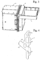
- the outer plugging position of the plug-in unit 12 is shown in Figure 3 .
- the locking counterpart element 15 is adapted to co-operate with the actuating member 9, while the actuating member 9 is in the locking position, in order to prevent movement of the plug-in unit 12 from the plugged-in position towards the detached position.
- the plug-in unit comprises at least one electrical component having an electrical connector arranged to be coupled to a corresponding mating connector installed in the case when the plug-in unit is being attached to its case.
- the outer plugging position is located such that substantially the entire coupling event, i.e. the coupling of the electrical connector to the mating connector, takes place between the outer plugging position and the plugged-in position. This reduces the force required to connect the plug-in unit to the case.
- the releasing counterpart element 16 is adapted to co-operate with the actuating member 9 for moving the plug-in unit 12 from the plugged-in position to an outer releasing position in relation to the case 13 in response to movement of the actuating member 9 from the locking position to the releasing position, the outer releasing position being located at a predetermined release distance from the plugged-in position towards the detached position.
- the outer releasing position is equal to the outer plugging position shown in Figure 3 . In an alternative embodiment, there is a distance between the outer plugging position and the outer releasing position.
- the locking counterpart element 15 is located in the upper half of the case 13.
- the releasing counterpart element 16 is located in the lower half of the case 13.
- the distance between the locking counterpart element 15 and the upper surface of the case 13 is identical to the distance between the releasing counterpart element 16 and the lower surface of the case 13.
- Figure 4 shows a side view of the actuating member 9.
- a circular connecting aperture 919 is provided on the upper end of the actuating member 9, and a linearly extending guiding slot 921 on the lower end of the actuating member 9.
- the actuating member 9 also comprises a locking surface 915 arranged to co-operate with the locking counterpart element 15, and a releasing surface 916 arranged to co-operate with the releasing counterpart element 16. Both the locking surface 915 and the releasing surface 916 extend perpendicularly in relation to the image plane of Figure 4 and are narrow, planar surfaces.
- the locking surface 915 forms an angle ⁇ in relation to an actuating member centre line 901 which extends between a centre point of the connecting aperture 919 and a centre point of the guiding slot 921.
- the releasing surface 916 forms an angle ⁇ in relation to the actuating member centre line 901.
- both the angle ⁇ and the angle ⁇ are approximately 50°.
- the angles ⁇ and ⁇ may be in a range of 30° to 70°.
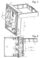
- FIG. 5 shows an upper corner of the interior of the unit body 121.
- a pivotal shaft 912 is formed on the handle 2, the pivotal shaft 912 having a free end adapted to be received in the connecting aperture 919 of the actuating member 9.
- the pivotal shaft 912 is located at a distance from a pivoting axis of the handle 2 and it allows the actuating member 9 to pivot in relation to the handle 2.
- a point through which the pivoting axis of the handle 2 passes is denoted with reference numeral 201.
- the pivotal shaft 912 is formed by a head of a hexagonal socket-head screw. The screw is screwed into the handle 2. Under the head of the screw a washer 955 is provided which prevents release of the handle 2 from the unit body 121.
- the pivotal shaft is formed by a portion of a shank of a screw.
- the screw may be screwed into the handle from outside the unit body.
- a screw is screwed into the actuating member and a portion of the screw forms the pivotal shaft.
- the connecting aperture is provided on the handle.
- FIGs 6 and 7 illustrate mounting of the actuating member 9 into the plug-in unit 12.
- no unit housing 128 is shown.
- the pivotal shaft 912 has been fitted in the connecting aperture 919 of the actuating member 9 in order to provide an off-centre pivotal connection 91.
- the off-centre pivotal connection 91 is located at a distance from the pivoting axis of the handle 2 and it allows the actuating member 9 to pivot in relation to the handle 2.
- the actuating member 9 is in a position where the actuating member centre line 901 extends at an angle greater than 45° in relation to the vertical direction D vert . This position of the actuating member 9 enables the pivotal shaft 912 to be fitted into the connecting aperture 919.
- the actuating member 9 is pivoted around the pivotal shaft 912 into a position where the actuating member centre line 901 extends substantially parallel with the vertical direction D vert as depicted in Figure 7 .
- a support screw 126 is screwed into the guiding slot 921 in order to provide a guiding slot connection 92.
- the support screw 126 has a free end which forms a slot pin 922 adapted to co-operate with the guiding slot 921 by sliding in the guiding slot 921.
- the support screw 126 is screwed from outside the unit body 121.
- Figure 7 shows that a lateral movement of the actuating member 9 is prevented when the actuating member centre line 901 extends substantially parallel with the vertical direction D vert .
- the lateral movement of the actuating member 9 is parallel with the pivoting axis of the handle 2.
- the lateral movement of the actuating member 9 is prevented by an inner side surface of the unit body 121, and on the other side the lateral movement of the actuating member 9 is prevented by guide pins 95.
- Figures 8 to 10 show a sectional view of the plug-in unit assembly, illustrating the operation of the actuating member 9.
- the upper part of the actuating member 9 is pivotally connected to the handle 2 through the off-centre pivotal connection 91 which allows the actuating member 9 to pivot in relation to the handle 2.
- the lower part of the actuating member 9 is connected to the unit body 121 through the guiding slot connection 92 as explained above.
- the handle 2 is in the mounting position, the actuating member 9 is in the releasing position, and the plug-in unit 12 is in the outer plugging position.
- the releasing surface 916 of the actuating member 9 is in contact with the releasing counterpart element 16.
- the locking surface 915 is at a distance from the locking counterpart element 15.
- the handle 2 is in the normal position, the actuating member 9 is in the locking position, and the plug-in unit 12 is in the plugged-in position.
- the locking surface 915 of the actuating member 9 is in contact with the locking counterpart element 15.
- the releasing surface 916 is at a distance from the releasing counterpart element 16.
- the movement of the plug-in unit 12 from the outer plugging position of Figure 8 to the plugged-in position of Figure 10 is achieved by turning the handle 2 from the mounting position to the normal position.
- the turning of the handle 2 moves the actuating member 9 from the releasing position to the locking position owing to the off-centre pivotal connection 91 which moves the pivotal shaft 912 upwards and in a detaching direction D dtc in relation to the unit body 121.
- the upwards direction is a direction parallel to the vertical direction D vert and directed away from the slot pin 922.
- the detaching direction D dtc is a direction opposite to the mounting direction D mnt .
- Figure 9 illustrates an intermediate state between the states illustrated in Figures 8 and 10 .
- the locking surface 915 co-operates with the locking counterpart element 15 transferring forces that move the plug-in unit 12 towards the plugged-in position.
- Figures 8 to 10 show that the handle 2 provides a long lever arm, almost as long as the height of the front surface of the unit body 121. This is made possible by locating the pivoting axis of the handle 2 near the upper surface of the unit body 121.
- the long lever arm of the handle 2 reduces the force necessary to operate the handle 2.
Landscapes
- Engineering & Computer Science (AREA)
- Microelectronics & Electronic Packaging (AREA)
- Details Of Connecting Devices For Male And Female Coupling (AREA)
- Lock And Its Accessories (AREA)
Claims (11)
- Einsteckanordnung, umfassend ein Gehäuse (13) und eine Steckeinheit (12), die eingerichtet ist, entfernbar mit dem Gehäuse (13) verbunden zu sein, die Steckeinheit (12) aufweisend eine eingesteckte Position und eine getrennte Position in Bezug auf das Gehäuse (13);
die Steckeinheit (12) umfassend einen Einheitskörper (121), einen Griff (2) und ein Betätigungselement (9), wobei der Griff (2) zur Drehung zwischen einer Normalposition und einer Montageposition in Bezug auf den Einheitskörper (121) drehbar mit dem Einheitskörper (121) verbunden ist, wobei das Betätigungselement (9) zur Bewegung zwischen einer Verriegelungsposition und einer Entriegelungsposition in Bezug auf den Einheitskörper (121) beweglich mit dem Einheitskörper (121) verbunden ist, wobei der Griff (2) funktional derart mit dem Betätigungselement (9) verbunden ist, dass ein Drehen des Griffs (2) aus der Montageposition in die Normalposition das Betätigungselement (9) aus der Entriegelungsposition in die Verriegelungsposition bewegt, und ein Drehen des Griffs (2) aus der Normalposition in die Montageposition das Betätigungselement (9) aus der Verriegelungsposition in die Entriegelungsposition bewegt;
das Gehäuse (13) umfassend ein Verriegelungs-Gegenelement (15) und ein Entriegelungs-Gegenelement (16), wobei das Verriegelungs-Gegenelement (15) ausgelegt ist, mit dem Betätigungselement (9) zum Bewegen der Steckeinheit (12) aus einer äußeren Steckposition in die eingesteckte Position in Reaktion auf eine Bewegung des Betätigungselements (9) aus der Entriegelungsposition in die Verriegelungsposition zusammenzuwirken, wobei sich die äußere Steckposition in einem vorbestimmten Steckabstand von der eingesteckten Position in Richtung der getrennten Position befindet, und wobei
das Entriegelungs-Gegenelement (16) ausgelegt ist, mit dem Betätigungselement (9) zum Bewegen der Steckeinheit (12) aus der eingesteckten Position in eine äußere Entriegelungsposition in Bezug auf das Gehäuse (13) in Reaktion auf eine Bewegung des Betätigungselements (9) aus der Verriegelungsposition in die Entriegelungsposition zusammenzuwirken, wobei sich die äußere Entriegelungsposition in einem vorbestimmten Entriegelungsabstand von der eingesteckten Position in Richtung der getrennten Position befindet,
das Betätigungselement (9) umfasst eine Verriegelungsfläche (915), die eingerichtet ist, mit dem Verriegelungs-Gegenelement (15) zusammenzuwirken, und eine Entriegelungsfläche (916), die eingerichtet ist, mit dem Entriegelungs-Gegenelement (16) zusammenzuwirken,
dadurch gekennzeichnet, dass
der Griff einen kreisförmigen Drehabschnitt umfasst, der die Drehverbindung zwischen dem Griff und dem Einheitskörper bereitstellt, wobei der Einheitskörper eine kreisförmige Öffnung in der Seitenwand des Gehäuses zur Aufnahme des kreisförmigen Drehabschnitts des Griffs umfasst,
die Drehachse des Griffs senkrecht zu der Seitenwand ist und in der Mitte des kreisförmigen Drehabschnitts und der kreisförmigen Öffnung angeordnet ist,
das Betätigungselement (9) durch eine außermittige Drehverbindung (91) drehbar mit dem Griff (2) verbunden ist, wobei die außermittige Drehverbindung (91) im Inneren des Einheitskörpers angeordnet ist, und die außermittige Drehverbindung eine Drehwelle (912), die auf einem von dem Griff (2) und dem Betätigungselement (9) vorgesehen ist, wobei die Drehwelle (912) ein freies Ende aufweist; und ein Verbindungsloch (919) umfasst, das auf dem anderen von dem Griff (2) und dem Betätigungselement (9) vorgesehen ist, wobei das Verbindungsloch (919) ausgelegt ist, das freie Ende der Drehwelle (912) zum Verwirklichen der außermittigen Drehverbindung (91) aufzunehmen, und die Drehwelle in einem Abstand von einer Drehachse des Griffs (2) und der außermittigen Verbindung angeordnet ist, um dem Betätigungselement (9) ein Drehen in Bezug auf den Griff (2) zu erlauben, das Betätigungselement durch eine Führungsschlitzverbindung mit dem Einheitskörper verbunden ist, und die außermittige Drehverbindung (91) derart angeordnet ist, dass ein Drehen des Griffs (2) aus der Montageposition in die Normalposition die Drehwelle (912) aufwärts und in eine Trennrichtung (Ddtc) bewegt, wobei die Aufwärtsrichtung eine Richtung parallel zu einer vertikalen Richtung (Dvert) und von der Führungsschlitzverbindung (92) weg gerichtet ist, wobei die Trennrichtung (Ddtc) eine Richtung entgegengesetzt zu einer Montagerichtung (Dmnt) ist, wobei die vertikale Richtung (Dvert) senkrecht sowohl in Bezug auf die Drehachse des Griffs (2) als auch die Montagerichtung (Dmnt) ist, wobei die Montagerichtung (Dmnt) eine Richtung ist, in welche die Steckeinheit (12) ausgelegt ist, gestoßen zu werden, wenn die Steckeinheit (12) mit dem Gehäuse (13) verbunden wird. - Einsteckanordnung nach Anspruch 1, dadurch gekennzeichnet, dass die Drehwelle (912) auf dem Griff (2) vorgesehen ist, und das Verbindungsloch (919) auf dem Betätigungselement (9) vorgesehen ist.
- Einsteckanordnung nach einem der vorhergehenden Ansprüche, dadurch gekennzeichnet, dass die Führungsschlitzverbindung (92) einen Führungsschlitz (921), der auf einem von dem Betätigungselement (9) und dem Einheitskörper (121) vorgesehen ist, und einen Schlitzstift (922) umfasst, der auf dem anderen von dem Betätigungselement (9) und dem Einheitsgehäuse (121) vorgesehen ist, wobei der Schlitzstift (922) ausgelegt ist, mit dem Führungsschlitz (921) durch Gleiten im Führungsschlitz (921) zusammenzuwirken.
- Einsteckanordnung nach Anspruch 3, dadurch gekennzeichnet, dass der Führungsschlitz (921) linear verläuft.
- Einsteckanordnung nach Anspruch 3 oder 4, dadurch gekennzeichnet, dass der Führungsschlitz (921) auf dem Betätigungselement (9) vorgesehen ist, und der Schlitzstift (922) auf dem Einheitskörper (121) vorgesehen ist.
- Einsteckanordnung nach Anspruch 1, dadurch gekennzeichnet, dass
die außermittige Drehverbindung (91) eine Drehwelle (912), die auf dem Griff (2) vorgesehen ist, und ein Verbindungsloch (919) umfasst, das auf dem Betätigungselement (9) vorgesehen ist, wobei die Drehwelle (912) ein freies Ende aufweist, und wobei das Verbindungsloch (919) ausgelegt ist, das freie Ende der Drehwelle (912) zum Verwirklichen der außermittigen Drehverbindung (91) aufzunehmen;
der Führungsschlitz (921) linear verläuft und auf dem Betätigungselement (9) vorgesehen ist, und die Führungsschlitzverbindung (92) ferner einen Schlitzstift (922) umfasst, der auf dem Einheitskörper (121) vorgesehen und ausgelegt ist, mit dem Führungsschlitz (921) durch Gleiten im Führungsschlitz (921) zusammenzuwirken; und
sowohl die Verriegelungsfläche (915) als auch die Entriegelungsfläche (916) ebene Flächen sind, wobei die Verriegelungsfläche (915) einen Winkel α in Bezug auf eine Mittellinie (901) des Betätigungselements bildet, welche zwischen einem Mittelpunt des Verbindungslochs (919) und einem Mittelpunkt des Führungsschlitzes (921) verläuft, und wobei die Entriegelungsfläche (916) einen Winkel β in Bezug auf die Mittellinie (901) des Betätigungselements bildet. - Einsteckanordnung nach Anspruch 6, dadurch kennzeichnet, dass sowohl der Winkel α als auch der Winkel β in einem Bereich von 30° bis 70° liegen.
- Einsteckanordnung nach einem der vorhergehenden Ansprüche, dadurch gekennzeichnet, dass das Verriegelungs-Gegenelement (15) eine Umfangsfläche umfasst, die ausgelegt ist, mit der Verriegelungsfläche (915) zusammenzuwirken, und das Entriegelungs-Gegenelement (16) eine Umfangsfläche umfasst, die ausgelegt ist, mit der Entriegelungsfläche (916) zusammenzuwirken, wobei jede der Umfangsflächen eine symmetrische und zylindrische Fläche mit einer Symmetrieachse parallel zur Drehachse des Griffs (2) ist.
- Einsteckanordnung nach Anspruch 8, dadurch gekennzeichnet, dass zumindest eines der Folgenden: die Drehwelle (912), das Verriegelungs-Gegenelement (15) und das Entriegelungs-Gegenelement (16) durch einen Abschnitt einer Schraube gebildet ist.
- Einsteckanordnung nach einem der vorhergehenden Ansprüche, dadurch gekennzeichnet, dass das Verriegelungs-Gegenelement (15) und das Entriegelungs-Gegenelement (16) voneinander beabstandet und auf einer vertikalen Linie angeordnet sind, wobei die vertikale Linie parallel zu einer vertikalen Richtung (Dvert) ist, die sowohl in Bezug auf die Drehachse des Griffs (2) als auch eine Montagerichtung (Dmnt) senkrecht ist, wobei die Montagerichtung (Dmnt) eine Richtung ist, in welche die Steckeinheit (12) ausgelegt ist, gestoßen zu werden, wenn die Steckeinheit (12) mit dem Gehäuse (13) verbunden wird.
- Einsteckanordnung nach einem der vorhergehenden Ansprüche, dadurch gekennzeichnet, dass das Betätigungselement (9) ausgelegt ist, um, während es in der Verriegelungsposition ist, mit dem Verriegelungs-Gegenelement (15) zusammenzuwirken, um eine Bewegung der Steckeinheit (12) aus der eingesteckten Position in Richtung der getrennten Position zu verhindern.
Priority Applications (5)
| Application Number | Priority Date | Filing Date | Title |
|---|---|---|---|
| EP14150937.2A EP2720522B8 (de) | 2010-05-19 | 2010-05-19 | Einsteckanordnung |
| EP10163244.6A EP2389054B1 (de) | 2010-05-19 | 2010-05-19 | Einsteckanordnung |
| CN201110126513.3A CN102256466B (zh) | 2010-05-19 | 2011-05-13 | 插入单元组件 |
| US13/110,363 US8231396B2 (en) | 2010-05-19 | 2011-05-18 | Plug-in-unit assembly with an off-center pivotal connection between a handle and an actuating member |
| RU2011119777/07A RU2474096C1 (ru) | 2010-05-19 | 2011-05-18 | Подключаемый блок агрегата |
Applications Claiming Priority (1)
| Application Number | Priority Date | Filing Date | Title |
|---|---|---|---|
| EP10163244.6A EP2389054B1 (de) | 2010-05-19 | 2010-05-19 | Einsteckanordnung |
Related Child Applications (2)
| Application Number | Title | Priority Date | Filing Date |
|---|---|---|---|
| EP14150937.2A Division EP2720522B8 (de) | 2010-05-19 | 2010-05-19 | Einsteckanordnung |
| EP14150937.2A Division-Into EP2720522B8 (de) | 2010-05-19 | 2010-05-19 | Einsteckanordnung |
Publications (3)
| Publication Number | Publication Date |
|---|---|
| EP2389054A1 EP2389054A1 (de) | 2011-11-23 |
| EP2389054A9 EP2389054A9 (de) | 2012-01-18 |
| EP2389054B1 true EP2389054B1 (de) | 2014-08-06 |
Family
ID=42983310
Family Applications (2)
| Application Number | Title | Priority Date | Filing Date |
|---|---|---|---|
| EP14150937.2A Active EP2720522B8 (de) | 2010-05-19 | 2010-05-19 | Einsteckanordnung |
| EP10163244.6A Active EP2389054B1 (de) | 2010-05-19 | 2010-05-19 | Einsteckanordnung |
Family Applications Before (1)
| Application Number | Title | Priority Date | Filing Date |
|---|---|---|---|
| EP14150937.2A Active EP2720522B8 (de) | 2010-05-19 | 2010-05-19 | Einsteckanordnung |
Country Status (4)
| Country | Link |
|---|---|
| US (1) | US8231396B2 (de) |
| EP (2) | EP2720522B8 (de) |
| CN (1) | CN102256466B (de) |
| RU (1) | RU2474096C1 (de) |
Cited By (1)
| Publication number | Priority date | Publication date | Assignee | Title |
|---|---|---|---|---|
| USD724073S1 (en) | 2013-08-29 | 2015-03-10 | Abb Technology Ag | Intelligent electronic device enclosure |
Families Citing this family (10)
| Publication number | Priority date | Publication date | Assignee | Title |
|---|---|---|---|---|
| FR2986937B1 (fr) * | 2012-02-14 | 2014-12-12 | Schneider Electric Ind Sas | Dispositif support extractible pour equipement electrique |
| CN104244657B (zh) * | 2013-06-14 | 2017-11-07 | 鸿富锦精密电子(天津)有限公司 | 电子装置及其电源固定装置 |
| US9451719B2 (en) | 2013-08-29 | 2016-09-20 | Abb Technology Ag | U form-factor intelligent electronic device (IED) hardware platform with matching of IED wiring, from a non U form-factor IED hardware platform using adapter structure |
| US9510475B2 (en) | 2013-08-29 | 2016-11-29 | Abb Schweiz Ag | Mechanical assembly and method to provide form-factor and wire alike adaptation of existing platform hardware modules into new products |
| US9568963B2 (en) * | 2014-03-29 | 2017-02-14 | Lenovo (Singapore) Pte. Ltd. | Computer power supply assembly |
| US9811128B2 (en) * | 2014-09-08 | 2017-11-07 | Dell Products L.P. | Structural subassembly for use in an information handling system chassis |
| CN204761920U (zh) * | 2015-06-17 | 2015-11-11 | 中兴通讯股份有限公司 | 快速免工具安装的通讯设备框体架构 |
| US9629263B2 (en) * | 2015-08-10 | 2017-04-18 | Lenovo Enterprise Solutions (Singapore) Pte. Ltd. | Apparatus and system for multifunction camming support shelf |
| EP4104033A1 (de) * | 2020-02-11 | 2022-12-21 | Schneider Electric IT Corporation | Elektrisches basismodul für modulare datenzentrale |
| RU198474U1 (ru) * | 2020-03-25 | 2020-07-13 | Российская Федерация, От Имени Которой Выступает Министерство Промышленности И Торговли Российской Федерации | Подключаемый блок |
Family Cites Families (17)
| Publication number | Priority date | Publication date | Assignee | Title |
|---|---|---|---|---|
| SU1339912A1 (ru) * | 1985-06-21 | 1987-09-23 | Предприятие П/Я Г-4677 | Запирающее устройство |
| SU1309339A1 (ru) * | 1985-12-09 | 1987-05-07 | Предприятие П/Я А-1001 | Устройство дл креплени |
| KR0148533B1 (ko) * | 1995-09-19 | 1998-11-02 | 김광호 | 통신/전송기기 장비의 래크의 셀프로킹장치 |
| US5791753A (en) * | 1996-08-29 | 1998-08-11 | Compaq Computer Corp. | Computer component handle assembly |
| US5949652A (en) * | 1997-10-24 | 1999-09-07 | Dell U.S.A., L.P. | Computer power supply insertion and extraction apparatus and method |
| US6137684A (en) * | 1998-04-21 | 2000-10-24 | International Business Machines Corporation | Camming mechanism for joining modular electronic enclosures |
| US6222736B1 (en) * | 1999-01-26 | 2001-04-24 | Dell Usa, L.P. | Computer with component installation handle |
| TW428743U (en) * | 1999-03-16 | 2001-04-01 | Hon Hai Prec Ind Co Ltd | Case body separation mechanism of electronic apparatus |
| US6671184B1 (en) * | 2002-07-12 | 2003-12-30 | International Business Machines Corporation | Latching and locking handles |
| TW587730U (en) * | 2002-07-26 | 2004-05-11 | Hon Hai Prec Ind Co Ltd | A retainer device for drive bracket |
| FI119073B (fi) | 2003-05-06 | 2008-07-15 | Abb Oy | Pistoyksikön lukitus- ja irrotusmekanismi |
| CN100462895C (zh) * | 2005-09-05 | 2009-02-18 | 鸿富锦精密工业(深圳)有限公司 | 刀片式服务器背板测试治具 |
| CN201194202Y (zh) * | 2007-03-23 | 2009-02-11 | 安士能有限公司 | 一种用于转换电连接的装置 |
| US7586748B2 (en) * | 2007-04-23 | 2009-09-08 | Super Micro Computer, Inc. | Clasp device for a handle of a power supply |
| US7675754B2 (en) * | 2007-09-20 | 2010-03-09 | International Business Machines Corporation | Mechanically-assisted insertion and removal of modular device |
| US8040687B2 (en) * | 2008-03-27 | 2011-10-18 | Methode Electronics, Inc. | Retracting lock mechanism for an electronics device |
| US7771218B2 (en) * | 2008-05-05 | 2010-08-10 | Dell Products L.P. | Electrical coupler mating system |
-
2010
- 2010-05-19 EP EP14150937.2A patent/EP2720522B8/de active Active
- 2010-05-19 EP EP10163244.6A patent/EP2389054B1/de active Active
-
2011
- 2011-05-13 CN CN201110126513.3A patent/CN102256466B/zh active Active
- 2011-05-18 US US13/110,363 patent/US8231396B2/en active Active
- 2011-05-18 RU RU2011119777/07A patent/RU2474096C1/ru not_active IP Right Cessation
Cited By (1)
| Publication number | Priority date | Publication date | Assignee | Title |
|---|---|---|---|---|
| USD724073S1 (en) | 2013-08-29 | 2015-03-10 | Abb Technology Ag | Intelligent electronic device enclosure |
Also Published As
| Publication number | Publication date |
|---|---|
| EP2720522A1 (de) | 2014-04-16 |
| EP2389054A1 (de) | 2011-11-23 |
| US8231396B2 (en) | 2012-07-31 |
| CN102256466A (zh) | 2011-11-23 |
| EP2720522B1 (de) | 2018-07-04 |
| EP2720522B8 (de) | 2018-08-15 |
| EP2389054A9 (de) | 2012-01-18 |
| CN102256466B (zh) | 2014-12-03 |
| RU2474096C1 (ru) | 2013-01-27 |
| US20110287650A1 (en) | 2011-11-24 |
| RU2011119777A (ru) | 2012-11-27 |
Similar Documents
| Publication | Publication Date | Title |
|---|---|---|
| EP2389054B1 (de) | Einsteckanordnung | |
| US9608369B1 (en) | Connector system with connector position assurance | |
| US8834190B2 (en) | Electrical connector with latch | |
| US9054456B2 (en) | Power connector assembly having an alignment body | |
| US7864522B1 (en) | Hard disk drive holder | |
| US8043106B1 (en) | Low profile socket connector with flexing lock arm | |
| US20130040482A1 (en) | Electrical connector with side-mounted latch | |
| JP2019509616A (ja) | コネクタ位置保証を有するコネクタシステム | |
| US8721348B2 (en) | Daughter card assembly having a guide element | |
| US9263809B2 (en) | Terminal block | |
| US8724955B2 (en) | Ejection mechanism and actuator for small form factor pluggable unit | |
| US10297962B1 (en) | Electrical connector for a power busbar | |
| US20210270056A1 (en) | Latch for a computing system | |
| US20130273780A1 (en) | Connector | |
| US12451649B2 (en) | Ganged coaxial connector assembly with latch | |
| US7534133B2 (en) | Electrical connector assembly with alignment pin | |
| US9160109B2 (en) | Lever actuated electrical center assembly | |
| CN105244686A (zh) | 一种连接器 | |
| JP2003077585A (ja) | ケーブルコネクタ | |
| JP2008147008A (ja) | 電気コネクタ | |
| JP4082512B2 (ja) | 垂直嵌合コネクタ | |
| CN214673227U (zh) | 一种电子连接器 | |
| KR100969115B1 (ko) | 커넥터 결합장치 | |
| KR101632704B1 (ko) | 커넥터 어셈블리 | |
| KR100996146B1 (ko) | 암형 커넥터 핀 고정장치 |
Legal Events
| Date | Code | Title | Description |
|---|---|---|---|
| 17P | Request for examination filed |
Effective date: 20110518 |
|
| AK | Designated contracting states |
Kind code of ref document: A1 Designated state(s): AL AT BE BG CH CY CZ DE DK EE ES FI FR GB GR HR HU IE IS IT LI LT LU LV MC MK MT NL NO PL PT RO SE SI SK SM TR |
|
| AX | Request for extension of the european patent |
Extension state: BA ME RS |
|
| PUAI | Public reference made under article 153(3) epc to a published international application that has entered the european phase |
Free format text: ORIGINAL CODE: 0009012 |
|
| 17Q | First examination report despatched |
Effective date: 20120111 |
|
| GRAP | Despatch of communication of intention to grant a patent |
Free format text: ORIGINAL CODE: EPIDOSNIGR1 |
|
| INTG | Intention to grant announced |
Effective date: 20140311 |
|
| GRAS | Grant fee paid |
Free format text: ORIGINAL CODE: EPIDOSNIGR3 |
|
| GRAA | (expected) grant |
Free format text: ORIGINAL CODE: 0009210 |
|
| AK | Designated contracting states |
Kind code of ref document: B1 Designated state(s): AL AT BE BG CH CY CZ DE DK EE ES FI FR GB GR HR HU IE IS IT LI LT LU LV MC MK MT NL NO PL PT RO SE SI SK SM TR |
|
| REG | Reference to a national code |
Ref country code: GB Ref legal event code: FG4D |
|
| REG | Reference to a national code |
Ref country code: CH Ref legal event code: EP Ref country code: AT Ref legal event code: REF Ref document number: 681556 Country of ref document: AT Kind code of ref document: T Effective date: 20140815 |
|
| REG | Reference to a national code |
Ref country code: IE Ref legal event code: FG4D |
|
| REG | Reference to a national code |
Ref country code: DE Ref legal event code: R096 Ref document number: 602010017992 Country of ref document: DE Effective date: 20140918 |
|
| REG | Reference to a national code |
Ref country code: AT Ref legal event code: MK05 Ref document number: 681556 Country of ref document: AT Kind code of ref document: T Effective date: 20140806 |
|
| REG | Reference to a national code |
Ref country code: NL Ref legal event code: VDEP Effective date: 20140806 |
|
| REG | Reference to a national code |
Ref country code: LT Ref legal event code: MG4D |
|
| PG25 | Lapsed in a contracting state [announced via postgrant information from national office to epo] |
Ref country code: GR Free format text: LAPSE BECAUSE OF FAILURE TO SUBMIT A TRANSLATION OF THE DESCRIPTION OR TO PAY THE FEE WITHIN THE PRESCRIBED TIME-LIMIT Effective date: 20141107 Ref country code: SE Free format text: LAPSE BECAUSE OF FAILURE TO SUBMIT A TRANSLATION OF THE DESCRIPTION OR TO PAY THE FEE WITHIN THE PRESCRIBED TIME-LIMIT Effective date: 20140806 Ref country code: NO Free format text: LAPSE BECAUSE OF FAILURE TO SUBMIT A TRANSLATION OF THE DESCRIPTION OR TO PAY THE FEE WITHIN THE PRESCRIBED TIME-LIMIT Effective date: 20141106 Ref country code: BG Free format text: LAPSE BECAUSE OF FAILURE TO SUBMIT A TRANSLATION OF THE DESCRIPTION OR TO PAY THE FEE WITHIN THE PRESCRIBED TIME-LIMIT Effective date: 20141106 Ref country code: LT Free format text: LAPSE BECAUSE OF FAILURE TO SUBMIT A TRANSLATION OF THE DESCRIPTION OR TO PAY THE FEE WITHIN THE PRESCRIBED TIME-LIMIT Effective date: 20140806 Ref country code: ES Free format text: LAPSE BECAUSE OF FAILURE TO SUBMIT A TRANSLATION OF THE DESCRIPTION OR TO PAY THE FEE WITHIN THE PRESCRIBED TIME-LIMIT Effective date: 20140806 Ref country code: PT Free format text: LAPSE BECAUSE OF FAILURE TO SUBMIT A TRANSLATION OF THE DESCRIPTION OR TO PAY THE FEE WITHIN THE PRESCRIBED TIME-LIMIT Effective date: 20141209 |
|
| PG25 | Lapsed in a contracting state [announced via postgrant information from national office to epo] |
Ref country code: IS Free format text: LAPSE BECAUSE OF FAILURE TO SUBMIT A TRANSLATION OF THE DESCRIPTION OR TO PAY THE FEE WITHIN THE PRESCRIBED TIME-LIMIT Effective date: 20141206 Ref country code: AT Free format text: LAPSE BECAUSE OF FAILURE TO SUBMIT A TRANSLATION OF THE DESCRIPTION OR TO PAY THE FEE WITHIN THE PRESCRIBED TIME-LIMIT Effective date: 20140806 Ref country code: HR Free format text: LAPSE BECAUSE OF FAILURE TO SUBMIT A TRANSLATION OF THE DESCRIPTION OR TO PAY THE FEE WITHIN THE PRESCRIBED TIME-LIMIT Effective date: 20140806 Ref country code: NL Free format text: LAPSE BECAUSE OF FAILURE TO SUBMIT A TRANSLATION OF THE DESCRIPTION OR TO PAY THE FEE WITHIN THE PRESCRIBED TIME-LIMIT Effective date: 20140806 Ref country code: CY Free format text: LAPSE BECAUSE OF FAILURE TO SUBMIT A TRANSLATION OF THE DESCRIPTION OR TO PAY THE FEE WITHIN THE PRESCRIBED TIME-LIMIT Effective date: 20140806 Ref country code: LV Free format text: LAPSE BECAUSE OF FAILURE TO SUBMIT A TRANSLATION OF THE DESCRIPTION OR TO PAY THE FEE WITHIN THE PRESCRIBED TIME-LIMIT Effective date: 20140806 Ref country code: PL Free format text: LAPSE BECAUSE OF FAILURE TO SUBMIT A TRANSLATION OF THE DESCRIPTION OR TO PAY THE FEE WITHIN THE PRESCRIBED TIME-LIMIT Effective date: 20140806 |
|
| PG25 | Lapsed in a contracting state [announced via postgrant information from national office to epo] |
Ref country code: SK Free format text: LAPSE BECAUSE OF FAILURE TO SUBMIT A TRANSLATION OF THE DESCRIPTION OR TO PAY THE FEE WITHIN THE PRESCRIBED TIME-LIMIT Effective date: 20140806 Ref country code: CZ Free format text: LAPSE BECAUSE OF FAILURE TO SUBMIT A TRANSLATION OF THE DESCRIPTION OR TO PAY THE FEE WITHIN THE PRESCRIBED TIME-LIMIT Effective date: 20140806 Ref country code: DK Free format text: LAPSE BECAUSE OF FAILURE TO SUBMIT A TRANSLATION OF THE DESCRIPTION OR TO PAY THE FEE WITHIN THE PRESCRIBED TIME-LIMIT Effective date: 20140806 Ref country code: RO Free format text: LAPSE BECAUSE OF FAILURE TO SUBMIT A TRANSLATION OF THE DESCRIPTION OR TO PAY THE FEE WITHIN THE PRESCRIBED TIME-LIMIT Effective date: 20140806 Ref country code: EE Free format text: LAPSE BECAUSE OF FAILURE TO SUBMIT A TRANSLATION OF THE DESCRIPTION OR TO PAY THE FEE WITHIN THE PRESCRIBED TIME-LIMIT Effective date: 20140806 |
|
| REG | Reference to a national code |
Ref country code: DE Ref legal event code: R097 Ref document number: 602010017992 Country of ref document: DE |
|
| PLBE | No opposition filed within time limit |
Free format text: ORIGINAL CODE: 0009261 |
|
| STAA | Information on the status of an ep patent application or granted ep patent |
Free format text: STATUS: NO OPPOSITION FILED WITHIN TIME LIMIT |
|
| 26N | No opposition filed |
Effective date: 20150507 |
|
| PG25 | Lapsed in a contracting state [announced via postgrant information from national office to epo] |
Ref country code: SI Free format text: LAPSE BECAUSE OF FAILURE TO SUBMIT A TRANSLATION OF THE DESCRIPTION OR TO PAY THE FEE WITHIN THE PRESCRIBED TIME-LIMIT Effective date: 20140806 |
|
| REG | Reference to a national code |
Ref country code: CH Ref legal event code: PL |
|
| PG25 | Lapsed in a contracting state [announced via postgrant information from national office to epo] |
Ref country code: LU Free format text: LAPSE BECAUSE OF FAILURE TO SUBMIT A TRANSLATION OF THE DESCRIPTION OR TO PAY THE FEE WITHIN THE PRESCRIBED TIME-LIMIT Effective date: 20150519 Ref country code: CH Free format text: LAPSE BECAUSE OF NON-PAYMENT OF DUE FEES Effective date: 20150531 Ref country code: MC Free format text: LAPSE BECAUSE OF FAILURE TO SUBMIT A TRANSLATION OF THE DESCRIPTION OR TO PAY THE FEE WITHIN THE PRESCRIBED TIME-LIMIT Effective date: 20140806 Ref country code: LI Free format text: LAPSE BECAUSE OF NON-PAYMENT OF DUE FEES Effective date: 20150531 |
|
| REG | Reference to a national code |
Ref country code: IE Ref legal event code: MM4A |
|
| PG25 | Lapsed in a contracting state [announced via postgrant information from national office to epo] |
Ref country code: IE Free format text: LAPSE BECAUSE OF NON-PAYMENT OF DUE FEES Effective date: 20150519 |
|
| REG | Reference to a national code |
Ref country code: FR Ref legal event code: PLFP Year of fee payment: 7 |
|
| PG25 | Lapsed in a contracting state [announced via postgrant information from national office to epo] |
Ref country code: BE Free format text: LAPSE BECAUSE OF FAILURE TO SUBMIT A TRANSLATION OF THE DESCRIPTION OR TO PAY THE FEE WITHIN THE PRESCRIBED TIME-LIMIT Effective date: 20140806 |
|
| PG25 | Lapsed in a contracting state [announced via postgrant information from national office to epo] |
Ref country code: MT Free format text: LAPSE BECAUSE OF FAILURE TO SUBMIT A TRANSLATION OF THE DESCRIPTION OR TO PAY THE FEE WITHIN THE PRESCRIBED TIME-LIMIT Effective date: 20140806 |
|
| REG | Reference to a national code |
Ref country code: DE Ref legal event code: R081 Ref document number: 602010017992 Country of ref document: DE Owner name: ABB SCHWEIZ AG, CH Free format text: FORMER OWNER: ABB TECHNOLOGY AG, ZUERICH, CH |
|
| REG | Reference to a national code |
Ref country code: FR Ref legal event code: PLFP Year of fee payment: 8 |
|
| PG25 | Lapsed in a contracting state [announced via postgrant information from national office to epo] |
Ref country code: HU Free format text: LAPSE BECAUSE OF FAILURE TO SUBMIT A TRANSLATION OF THE DESCRIPTION OR TO PAY THE FEE WITHIN THE PRESCRIBED TIME-LIMIT; INVALID AB INITIO Effective date: 20100519 Ref country code: SM Free format text: LAPSE BECAUSE OF FAILURE TO SUBMIT A TRANSLATION OF THE DESCRIPTION OR TO PAY THE FEE WITHIN THE PRESCRIBED TIME-LIMIT Effective date: 20140806 |
|
| PG25 | Lapsed in a contracting state [announced via postgrant information from national office to epo] |
Ref country code: TR Free format text: LAPSE BECAUSE OF FAILURE TO SUBMIT A TRANSLATION OF THE DESCRIPTION OR TO PAY THE FEE WITHIN THE PRESCRIBED TIME-LIMIT Effective date: 20140806 |
|
| REG | Reference to a national code |
Ref country code: FR Ref legal event code: PLFP Year of fee payment: 9 |
|
| REG | Reference to a national code |
Ref country code: GB Ref legal event code: 732E Free format text: REGISTERED BETWEEN 20180426 AND 20180502 |
|
| PG25 | Lapsed in a contracting state [announced via postgrant information from national office to epo] |
Ref country code: MK Free format text: LAPSE BECAUSE OF FAILURE TO SUBMIT A TRANSLATION OF THE DESCRIPTION OR TO PAY THE FEE WITHIN THE PRESCRIBED TIME-LIMIT Effective date: 20140806 |
|
| REG | Reference to a national code |
Ref country code: FR Ref legal event code: TP Owner name: ABB SCHWEIZ AG, CH Effective date: 20180912 |
|
| PG25 | Lapsed in a contracting state [announced via postgrant information from national office to epo] |
Ref country code: AL Free format text: LAPSE BECAUSE OF FAILURE TO SUBMIT A TRANSLATION OF THE DESCRIPTION OR TO PAY THE FEE WITHIN THE PRESCRIBED TIME-LIMIT Effective date: 20140806 |
|
| PGFP | Annual fee paid to national office [announced via postgrant information from national office to epo] |
Ref country code: FI Payment date: 20250526 Year of fee payment: 16 |
|
| PGFP | Annual fee paid to national office [announced via postgrant information from national office to epo] |
Ref country code: DE Payment date: 20250521 Year of fee payment: 16 |
|
| PGFP | Annual fee paid to national office [announced via postgrant information from national office to epo] |
Ref country code: GB Payment date: 20250521 Year of fee payment: 16 |
|
| PGFP | Annual fee paid to national office [announced via postgrant information from national office to epo] |
Ref country code: IT Payment date: 20250527 Year of fee payment: 16 |
|
| PGFP | Annual fee paid to national office [announced via postgrant information from national office to epo] |
Ref country code: FR Payment date: 20250528 Year of fee payment: 16 |