EP2388561B1 - Laborgerät zur Probenvorbereitung - Google Patents
Laborgerät zur Probenvorbereitung Download PDFInfo
- Publication number
- EP2388561B1 EP2388561B1 EP10163365.9A EP10163365A EP2388561B1 EP 2388561 B1 EP2388561 B1 EP 2388561B1 EP 10163365 A EP10163365 A EP 10163365A EP 2388561 B1 EP2388561 B1 EP 2388561B1
- Authority
- EP
- European Patent Office
- Prior art keywords
- work head
- laboratory instrument
- multifunctional
- head
- multifunctional work
- Prior art date
- Legal status (The legal status is an assumption and is not a legal conclusion. Google has not performed a legal analysis and makes no representation as to the accuracy of the status listed.)
- Not-in-force
Links
- 238000002360 preparation method Methods 0.000 title claims description 14
- 230000001681 protective effect Effects 0.000 claims description 43
- 238000007789 sealing Methods 0.000 claims description 33
- 238000004140 cleaning Methods 0.000 claims description 16
- 239000007788 liquid Substances 0.000 claims description 11
- 230000033001 locomotion Effects 0.000 claims description 11
- 238000005303 weighing Methods 0.000 claims description 10
- 239000000463 material Substances 0.000 claims description 5
- 238000000034 method Methods 0.000 description 8
- 239000007789 gas Substances 0.000 description 4
- 239000002904 solvent Substances 0.000 description 4
- 238000005520 cutting process Methods 0.000 description 3
- 238000001514 detection method Methods 0.000 description 3
- 239000000126 substance Substances 0.000 description 3
- 230000005540 biological transmission Effects 0.000 description 2
- 238000013461 design Methods 0.000 description 2
- 238000006073 displacement reaction Methods 0.000 description 2
- 238000000605 extraction Methods 0.000 description 2
- 230000005484 gravity Effects 0.000 description 2
- 238000005259 measurement Methods 0.000 description 2
- 239000002245 particle Substances 0.000 description 2
- 231100000614 poison Toxicity 0.000 description 2
- 239000003440 toxic substance Substances 0.000 description 2
- 230000002792 vascular Effects 0.000 description 2
- 240000003517 Elaeocarpus dentatus Species 0.000 description 1
- 238000007664 blowing Methods 0.000 description 1
- 230000001112 coagulating effect Effects 0.000 description 1
- 239000000428 dust Substances 0.000 description 1
- 238000001704 evaporation Methods 0.000 description 1
- 230000008020 evaporation Effects 0.000 description 1
- 230000009969 flowable effect Effects 0.000 description 1
- 239000012530 fluid Substances 0.000 description 1
- 239000012535 impurity Substances 0.000 description 1
- 239000011159 matrix material Substances 0.000 description 1
- 239000000203 mixture Substances 0.000 description 1
- 230000003287 optical effect Effects 0.000 description 1
- 239000000843 powder Substances 0.000 description 1
- 238000012545 processing Methods 0.000 description 1
- 230000035484 reaction time Effects 0.000 description 1
- 238000009738 saturating Methods 0.000 description 1
- 239000012780 transparent material Substances 0.000 description 1
- 238000012795 verification Methods 0.000 description 1
Images


Classifications
-
- G—PHYSICS
- G01—MEASURING; TESTING
- G01G—WEIGHING
- G01G19/00—Weighing apparatus or methods adapted for special purposes not provided for in the preceding groups
-
- G—PHYSICS
- G01—MEASURING; TESTING
- G01G—WEIGHING
- G01G21/00—Details of weighing apparatus
-
- G—PHYSICS
- G01—MEASURING; TESTING
- G01G—WEIGHING
- G01G23/00—Auxiliary devices for weighing apparatus
Definitions
- the present invention relates to a laboratory apparatus for providing samples.
- Sample preparation is becoming increasingly automated to reduce preparation time and eliminate potential errors that can occur during manual preparation.
- automated sample preparation a basic platform with individual treatment stations and a two- or three-axis robotic system are usually used.
- Such multifunctional laboratory equipment for example, in the EP 1 674 393 B1 . AU 2008200146 A1 . US 2004/0175295 A1 and US 5398556 disclosed.
- these laboratory devices have the disadvantage that they require a large area in relation to a laboratory balance, on which usually the sample preparation is carried out manually. If toxic substances have to be processed, the laboratory balance is placed in a working cabin with a suction device and the sample preparation is carried out there.
- the robot systems described above are usually too large, which is why they have their own, the entire system enclosing protective cabin. Accordingly, these multifunctional laboratory devices cost many times a laboratory balance. Furthermore, the cleaning effort of these systems is considerable solely due to the spatial extent of the staging area enclosed by the protective cabin, which is why, with a small number of samples to be provided, the automated sample preparation is still dispensed with. In contrast, the staging area of a laboratory balance, which is delimited by its windbreak, can be cleaned quickly and easily.
- Object of the present invention is therefore to provide a laboratory device for providing samples of the type described above, the staging space is kept as small as possible.
- a laboratory device for providing samples comprises a base housing with a provision space enclosed by protective walls and at least one multifunctional head mounted rotatably mounted on the base housing about a rotation axis.
- the latter has at least two defined functional positions, wherein each of these functional positions can be aligned by means of a rotation of the multifunctional head to at least one vessel receptacle arranged in the staging area.
- a target vessel can be placed in which afterwards the sample is filled and prepared.
- the first functional position includes a receiving device for receiving a metering device with flowable Dosiergut and every other functional position has ever a further device. As described below, these can be other recording devices, but also devices with other functions.
- At least one protective wall has an opening, wherein the at least one multifunctional head is arranged partially in the opening, so that a part of the multifunctional head is arranged outside the staging area and the other part of the multifunctional head within the staging area. Depending on the design of the multifunctional head, it can be rotated 360 ° or rotated only partially.
- the staging area very small, whereby the cleaning work is limited only to this small space. Furthermore, always a part of the multi-function head outside the staging area and thus the arranged in this part function positions accessible.
- the receiving device located outside the staging area may be equipped with a metering device, while metering stock is metered into the destination vessel with the other metering device located in the staging area.
- the embodiment of the invention offers enormous advantages, since the staging space has a very small volume and therefore the trapped air in this room quickly loses momentum when it is moved by changes in the staging area. This can happen, for example, when placing or removing a target vessel.
- the rotational movement of the multi-function head also causes extremely little air movements, since during the turning operation to this barely protruding parts may be present, which move the air mass in the staging space in motion.
- the multifunctional head may be populated during operation, thus, while the sample preparation is in progress, without having to open the ready room.
- High-resolution load cells are devices by means of which the mass of a sample can be measured accurately down to one microgram.
- load cells can be arranged in the base housing and connected to a respective vessel receptacle.
- multifunctional heads can be arranged on the basic housing.
- the axis of rotation of the at least one multi-function head can be arranged spatially arbitrary, but preferably it is arranged horizontally or vertically.
- the breakthrough is formed only in a protective wall.
- the at least one breakthrough can extend into at least two adjacent protective walls.
- the multi-functional head for at least partial release of the opening of the opening can be formed linearly displaceable and / or pivotable.
- a gripper of a laboratory robot can reach the vessel receptacle of the laboratory device without having to open one of the protective walls.
- the multi-functional head does not necessarily have to be designed to be partially displaceable or pivotable in order to partially open the opening of the opening.
- the multi-function head may also have a further functional position with an exemption. This release is brought to release the breakthrough in the appropriate position, so that a gripper of a laboratory robot can extend through this exemption in the staging area.
- the multifunctional head may further comprise a first plane and at least a second plane which are arranged orthogonal to the axis of rotation. At least one first functional position is formed in the first level and another functional position in the at least second level on the multi-function head. Both the first plane and the second plane can be brought into line with the vessel receptacle by linear displacement of the multifunctional head along its axis of rotation. It is also conceivable that the multi-function head is divided into several sections, each section containing a plane and the individual sections are independently rotatable about the common axis of rotation.
- one or more protective walls can also be designed to be displaceable or pivotable relative to the main housing, so that the provisioning space can be reached via open protective walls.
- the multifunction head completes the breakthrough and thus the staging area to the labware environment.
- the multifunctional head is not only a changing device or a process head with multiple functions, but also forms part of the protective walls.
- a sealing device can be arranged in the region of the opening. This sealing device preferably seals all gaps, exemptions and gaps that are inevitably present between the protective wall and the multi-functional head.
- the sealing device may be an elastic sealing strip, sealing brush or sealing roll arranged between the protective wall and the multifunctional head.
- the sealing device may also be a hood or a cover, which covers the opening and spans that part of the multi-function head, which is arranged outside the staging area.
- the sealing device may also be a hood or a cover, which covers the opening and spans that part of the multi-function head, which is arranged outside the staging area.
- a cleaning device for cleaning the multi-function head and / or the sealing device can be arranged in the region of the sealing device.
- this cleaning device may be a suction device, a suction device with additional blowing nozzles, rotating brushes and the like.
- the gap between the multi-function head and the protective wall is minimal or the sealing device always rests on the multi-function head, this may have a cylindrical basic shape.
- the multi-function head may also have any cross-sectional shapes, but preferably those in which the multi-function head can make at least one full turn in the breakthrough.
- the further functional positions of a multifunctional head can have a multiplicity of very different devices, for example a further receiving device for a dosing device, an electro-optical unit for identifying and / or positioning a target vessel on the vessel receptacle, a device for removing or placing the closure of a target vessel, a gripper for gripping objects, a liquid metering device, a liquid metering device receptacle or at least the outlet port of a liquid metering device, an electrostatic charge detection sensor, an ionizer, an identification device, a distance sensor or a cleaning device.
- the further functional positions of the multifunctional head and the other devices preferably have a standardized mechanical and electrical interface. The multifunctional head can thereby be easily equipped according to customer requirements with appropriate function modules.
- the functional positions may comprise devices which repeatedly fill larger quantities of a dosage material, for example a solvent, into the target vessel.
- the multi-function head can have at least one connection point for a connection line or an exchangeable extraction vessel.
- the discharge opening of the dosing device should be arranged directly above the filling opening of the target vessel during the dosing process.
- the distance between the vessel intake and the multifunctional head can be fixed.
- the multifunctional head is additionally arranged so as to be displaceable relative to the vessel receptacle in the vertical direction so as to be displaceable on the basic housing, so that target vessels of different height can be placed on the vessel receptacle.
- the at least one provided with the breakthrough protective wall can be designed to be vertically displaceable together with the multi-functional head.
- other walls without breakthrough together with the multi-function head can be displaced.
- the volume of the staging area of the vessel height can be adjusted, whereby this can always be kept to a minimum.
- the load cell can quickly deliver a stable weighing value in small target vessels, whereby small quantities can be metered with high precision.
- the resolution of the load cell that is to say its ability to clearly differentiate between measured values lying close to each other, can be controlled as a function of the space of provision of the measurement in order to keep the short reaction time of the measured value detection as far as possible.
- FIG. 1 In a three-dimensional view, a laboratory device 100 is shown in a first embodiment with a staging area 130 enclosed by protective walls 101, 102, 103, 104, 105, 106.
- the laboratory apparatus 100 has a base housing 110, which is divided into an upper part 112 and a lower part 111.
- the upper part 112 can be displaced linearly relative to the lower part 111 in the vertical direction.
- the lower part 111 is essentially a cuboidal box, in which a load cell, not shown, is arranged.
- a multi-function head 120 is rotatably mounted about a horizontal axis of rotation 121.
- the four of the protective walls 102, 103, 104, 105 extend in their vertical extent in the vertical direction, wherein two of the vertical protective walls side walls 102, 104, the third a front wall 103 and the fourth a rear wall 105 of the staging space 130.
- the two side walls 102, 104 are linearly displaceably connected to the upper part 112 in the horizontal direction.
- the front wall 103 is detachably connected to the upper part 112.
- the rear wall 105 is formed in two parts, wherein the first rear wall portion 107 with the lower part 111 and the second rear wall portion 108 with the upper part 112 are firmly connected. Further, the two rear wall portions 107, 108 are arranged partially overlapping each other, so that a displacement of the upper part 112 to the lower part 111 is made possible and the supply space 130 is separated in each shift position from the environment.
- the fifth protective wall 101 extends in its planar extent in the horizontal direction, is also firmly connected to the upper part 112 and forms the cover 101 of the staging space 130.
- a sixth protective wall 106 of the staging area 130 forms the bottom 106, whose areal extent also extends in the horizontal direction and which is firmly connected to the lower part 111.
- the vessel receptacle 131 arranged in the preparation space 130 is connected in a load-transmitting manner to the weighing cell arranged in the lower part 111.
- the front wall 103 and the two side walls 102, 104 are arranged to be guided past the box walls of the lower part 111, so that the upper part 112 can be moved vertically for this purpose unhindered.
- these protective walls 102, 103, 104 fit snugly against the box walls of the lower part 111, so that no air movements present in the surroundings are transmitted to the provisioning space 130 via excessively large leaks.
- the multifunction head 120 has a plurality of functional positions 122, 123, 124, which are equipped with different devices from each other, only three of these functional positions 122, 123, 124 are visible.
- a receiving device 126 is formed into which a metering device 140 is inserted.
- This metering device 140 has an outlet opening 141, which can be closed by a valve, not shown. The valve can be opened or closed by a drive device, also not shown.
- the metering device 140 is located outside the supply space 130, with its outlet opening 141 pointing in the direction opposite to the force of gravity.
- the multifunction head 120 is rotated until the metering device 140 is within the staging area 130, the outlet opening 141 points in the direction of gravity and can be discharged under the influence of the same metered material.
- pulverulent, coagulating dosing stock contained in the dosing device 140 can also be loosened, optionally by repeated rotation, by oscillating rotational movements and the like more.
- the metering device 140 can be inserted manually into the receiving device 126 of the multifunctional head 120, but also by means of a robot gripper 150.
- the robot and its robot gripper 150 outside the staging area 130.
- the multi-function head 120 can be linearly displaced along its axis of rotation 121, so that when retracted into the upper part 112 Multifunction head 120 of the opening 109 is released.
- this always remains outside the staging area, which is why only the robotic gripper 150 has to be cleaned occasionally.
- the volume of the staging area 130 can be minimized by the inventive arrangement of the multi-function head 120, so that the trapped air mass in the staging space 130 quickly comes to rest and a precise, rapid detection of the weighing values is made possible.
- the second functional position 123 has a lid opening device 127 and the third functional position 124 the outlet nozzle of a liquid metering device 128, not shown in detail.
- the lid opening device 127 can open a closure or a screw cap 161 of a target vessel 160
- two clamping devices 132, 133 are provided in the preparation space 130 at the side of the vessel receptacle 131, by means of which the target vessel 160 can be temporarily clamped to support the torque.
- the two clamping devices 132, 133 may be simultaneously displaceable in the horizontal plane, as indicated by the arrows.
- the target vessel 160 can not only be clamped but also precisely positioned with the aid of the clamping devices 132, 133.
- an optical aid can in the positioning process in FIG. 3 described camera serve whose image is transmitted to an unillustrated display of the laboratory device 100 and the user indicates how he has to move manually or by means of the input keyboard semi-automatic, the clamping devices.
- the image of the camera also in a laboratory device-internal Processing unit processed and performed by means of these data, the positioning process automatically.
- the clamping devices 132, 133 are completely separated from the target vessel 160, so that the weighing result is not influenced by the clamping devices 132, 133.
- FIG. 2 3 shows a three-dimensional view of a laboratory device 200 in a second embodiment with a staging area 230 enclosed by protective walls 201, 202, 203, 204, 205, 206.
- the laboratory device comprises a C-shaped base housing 210, wherein three walls of the main housing 210 also form protective walls of the staging area 230, namely its bottom 206, its rear wall 205 and its cover 201.
- the further protective walls, namely the front wall 203 and the two side walls 202, 204 are made of transparent material, so that the processes in the staging area 230 can be observed.
- the opening 209 extends in this laboratory device 200 via the one side wall 204 and the front wall 203.
- a multi-functional head 220 is arranged, the axis of rotation 221 is arranged in the vertical direction.
- This multifunctional head 220 also has a plurality of functional positions 222, 223, 224, wherein a further functional position is an exemption 225 for the partial release of the opening 209, by means of which a free passage to the provisioning space 230 can be created for a robot gripper 250.
- the protective walls 201, 202, 203, 204, 205, 206 need not be rigidly connected to the base housing 210 but can also, as in the first embodiment in FIG. 1 shown to be arranged linearly displaceable on this.
- the multi-function head 220 also has recesses 227 on its underside, so that, for example, a metering device 240 can be inserted from below into the receptacle of the first functional position 222 and removed again.
- a load cell is arranged, the load cell housing 234 protrudes partially from the bottom 206 and which is relative to the bottom 206 in the vertical direction linearly displaceable.
- FIG. 3 a partial section of a laboratory device 300 is shown in a sectional plan view, which largely corresponds to the in FIG. 1 shown laboratory device 100 corresponds, but the function positions 322, 323, 324 of the multifunction head 320 are partially equipped differently.
- a receiving device 326 is arranged, in which a metering device 340 is inserted.
- a liquid metering head 341 is arranged, which is supplied via a connecting line 342 with a liquid.
- the connecting line 342 also has a valve 353, through which the exiting amount of liquid can be controlled.
- the end of the connecting line 342 has a sharp cutting edge and protrudes into a connection point 343 for a removal vessel 344.
- connection point 343 must be able to accommodate the entire removal vessel 344 as shown, since otherwise the multifunctional head 320 can only be rotated to a limited extent.
- a pressure line 354 is connected to a compressed gas source 355, wherein the pressure line 354 also projects into the connection point 343 and has a cutting edge.
- the removal vessel 344 has a septum 349 which, as shown, can be pierced by means of the cutting edges in order to tap the contents of the removal vessel 344. It goes without saying that the arrangement and position shown is only one of many variants of how the extraction vessel 344 can be connected to the liquid metering head 341.
- One of the alternatives is, for example, that the connecting line 342 is passed out of the laboratory apparatus 300 through the basic housing and connected to an external supply station.
- a camera 345 is arranged, by means of which a target vessel 360 can be aligned on the vessel receptacle 331, so that during the subsequent metering operations, the outflowing metered product stream also reliably meets the filling opening 362 of the target vessel 360.
- the target vessel 360 may be identified with the camera 345, as long as it carries a readable label.
- the height of the target vessel 360 can be detected by means of the camera 345 so that the minimum distance H min between the multifunction head 320 and the inlet opening 362 can be established.
- a laser diode 356 may be arranged, the light beam parallel to Rotary axis is aligned.
- the upper edge of the target vessel 360 can be scanned precisely, since the light beam illuminates the filling opening 362 as soon as the desired distance H min is reached and this can be detected with the camera 345. In addition, it can be checked after dosing with the camera 345, whether the target vessel 360 has been filled correctly or whether, for example, traces of Dosierguts adhere to the edge of the filling opening 362.
- the edge of the opening 309 formed in the cover 301 surrounding the multifunction head 320 is provided with a sealing device in the form of a flexible sealing strip 346, the sealing surface of which is pressed against the cylindrical wall of the multifunctional head 320 with slight pressure.
- the illustrated cross-section of the sealing strip 346 is only one of many possible variants and to be understood by way of example. If particles adhering to the cylinder wall are to be wiped off during rotation, the sealing strip 346 can be provided with other profile cross sections with sharp edges, such as, for example, windscreen wiper blades.
- a further sealing device in the form of a hood 347 is present, which spans the part of the multifunctional head 320 arranged outside the staging area 330 and protects the multifunctional head 320 against unwanted access during certain operating phases of the laboratory device.
- the hood 347 is pivotally mounted on one side by means of a hinge 348 connected to the cover 301, so that it can be folded away to remove the metering device 340 from the receiving device 326 or use.
- the weighing cell 380 is connected in a load-transmitting manner to the vessel receptacle 331 by means of a transmission linkage 381.
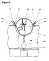
- FIG. 4 shows essentially the same subsection of the in FIG. 3 shown laboratory device in a sectional plan view, which is why all identical elements have the same reference numerals.
- the difference is that instead of the in FIG. 3 shown hood, the laboratory device 400 of the FIG. 4 a cleaning device 481 is arranged.
- the cleaning device 481 has one of the sealing strip 346 following, circumferential suction channel 482, which one to the sealing strip 346 out directed suction slot 483 has.
- the mouth of the suction slot 483 is located in the immediate vicinity of the line of contact between the multifunction head 320 and the sealing strip 346.
- the suction channel 482 is connected to a suction device, not shown, which sucks the air in the region of the sealing strip 346 at least during rotation of the multi-function head 320 continuously. If Dosiergut Wegdecknote on the cylinder surface of the multi-functional head 320, for example in wells, are not stripped from the sealing strip 346, they are sucked by the cleaning device 481 from the multifunction head 320. The same naturally also applies to impurities coming from the outside onto the multifunction head 320, such as dust particles, which are sucked off by the surface of the multifunctional head 320 which screws into the staging area 330.
- the vessel receptacle 331 On the vessel receptacle 331 is a target vessel 460 with an elongated vessel body, which is why the distance H between the multi-function head 320 and the vessel receptacle 331 is selected to be correspondingly greater than in FIG. 3 ,
- FIG. 5 essentially shows the inventive laboratory device FIG. 1 , where in FIG. 5 shown laboratory device 500 has a linearly displaceable multi-functional head 520, which extends beyond the staging area 530 addition. Accordingly, the opening 509 extends both over the entire cover 501 as well as over part of the front wall 503. As already in FIG. 1 described, the multifunction head 520 along its axis of rotation 521 can be moved arbitrarily. This allows functional positions 522, 525 to be disposed on different planes 513, 514 extending orthogonally to the axis of rotation 521. In the illustrated embodiment, a first level 513 is present, on which the first functional position 522 and the others, already in connection with FIG. 1 arranged functional positions are arranged.
- a fourth functional position 525 is formed on the multifunctional head 520. Both the first plane 513 and the second plane 514 can be brought into alignment with the vessel receptacle 531 by moving the multifunctional head 520 linearly.
- the laboratory device 500 also has a hood 547, which not as in the FIG. 3 is pivotable, but parallel to the multi-function head 520 in the same direction is linearly displaceable.
- the hood 547 in FIG. 5 is shown almost completely pushed into the upper part 512, so that the multi-function head 520 is better recognizable.
- the cleaning device may also be disposed in the ready room or that the cleaning device be used in combination with the hood can.
- a plurality of vessel receptacles can be arranged in the staging area, which are all connected load-transmitting together with a weighing cell or individually with an assigned weighing cell.
- Embodiments of the laboratory apparatus are also conceivable in which a plurality of multifunctional heads are present, which extend into the same ready room.
- identification means such as barcodes, matrix codes and / or radio-frequency identification means (RFID tags).
- RFID tags radio-frequency identification means
Landscapes
- Physics & Mathematics (AREA)
- General Physics & Mathematics (AREA)
- Automatic Analysis And Handling Materials Therefor (AREA)
- Sampling And Sample Adjustment (AREA)
- Manipulator (AREA)
Priority Applications (5)
| Application Number | Priority Date | Filing Date | Title |
|---|---|---|---|
| EP10163365.9A EP2388561B1 (de) | 2010-05-20 | 2010-05-20 | Laborgerät zur Probenvorbereitung |
| PL10163365T PL2388561T3 (pl) | 2010-05-20 | 2010-05-20 | Urządzenie laboratoryjne do przygotowywania próbek |
| US13/106,698 US8551421B2 (en) | 2010-05-20 | 2011-05-12 | Laboratory instrument for the preparation of samples |
| JP2011110339A JP5804767B2 (ja) | 2010-05-20 | 2011-05-17 | 試料準備のためのラボラトリ用計器 |
| CN201110135760.XA CN102323118B (zh) | 2010-05-20 | 2011-05-20 | 用于样品制备的实验仪器 |
Applications Claiming Priority (1)
| Application Number | Priority Date | Filing Date | Title |
|---|---|---|---|
| EP10163365.9A EP2388561B1 (de) | 2010-05-20 | 2010-05-20 | Laborgerät zur Probenvorbereitung |
Publications (2)
| Publication Number | Publication Date |
|---|---|
| EP2388561A1 EP2388561A1 (de) | 2011-11-23 |
| EP2388561B1 true EP2388561B1 (de) | 2015-12-02 |
Family
ID=42543431
Family Applications (1)
| Application Number | Title | Priority Date | Filing Date |
|---|---|---|---|
| EP10163365.9A Not-in-force EP2388561B1 (de) | 2010-05-20 | 2010-05-20 | Laborgerät zur Probenvorbereitung |
Country Status (5)
| Country | Link |
|---|---|
| US (1) | US8551421B2 (zh) |
| EP (1) | EP2388561B1 (zh) |
| JP (1) | JP5804767B2 (zh) |
| CN (1) | CN102323118B (zh) |
| PL (1) | PL2388561T3 (zh) |
Families Citing this family (35)
| Publication number | Priority date | Publication date | Assignee | Title |
|---|---|---|---|---|
| ES2534361T3 (es) * | 2011-06-20 | 2015-04-21 | F. Hoffmann-La Roche Ag | Dispositivo para destapar y re-tapar tubos de muestra |
| CN102829851A (zh) * | 2012-06-27 | 2012-12-19 | 郝志付 | 一种单体多格秤及称量方法 |
| WO2014033055A1 (en) | 2012-08-27 | 2014-03-06 | Aktiebolaget Electrolux | Robot positioning system |
| CN110448222A (zh) | 2013-04-15 | 2019-11-15 | 伊莱克斯公司 | 机器人真空吸尘器 |
| JP6198234B2 (ja) | 2013-04-15 | 2017-09-20 | アクティエボラゲット エレクトロラックス | 突出サイドブラシを備えたロボット真空掃除機 |
| WO2015090399A1 (en) | 2013-12-19 | 2015-06-25 | Aktiebolaget Electrolux | Robotic cleaning device and method for landmark recognition |
| WO2015090398A1 (en) | 2013-12-19 | 2015-06-25 | Aktiebolaget Electrolux | Robotic vacuum cleaner with side brush moving in spiral pattern |
| WO2015090404A1 (en) | 2013-12-19 | 2015-06-25 | Aktiebolaget Electrolux | Prioritizing cleaning areas |
| CN105744872B (zh) | 2013-12-19 | 2020-01-14 | 伊莱克斯公司 | 旋转侧刷的自适应速度控制 |
| WO2015090405A1 (en) | 2013-12-19 | 2015-06-25 | Aktiebolaget Electrolux | Sensing climb of obstacle of a robotic cleaning device |
| US9811089B2 (en) | 2013-12-19 | 2017-11-07 | Aktiebolaget Electrolux | Robotic cleaning device with perimeter recording function |
| US10209080B2 (en) | 2013-12-19 | 2019-02-19 | Aktiebolaget Electrolux | Robotic cleaning device |
| US10231591B2 (en) | 2013-12-20 | 2019-03-19 | Aktiebolaget Electrolux | Dust container |
| KR102325130B1 (ko) | 2014-07-10 | 2021-11-12 | 에이비 엘렉트로룩스 | 로봇 청소 장치에서 측정 에러를 검출하는 방법 |
| KR102271782B1 (ko) | 2014-09-08 | 2021-06-30 | 에이비 엘렉트로룩스 | 로봇 진공 청소기 |
| CN106716086A (zh) | 2014-09-08 | 2017-05-24 | 贝克顿·迪金森公司 | 用于制备药物化合物的系统和方法 |
| EP3190939B1 (en) | 2014-09-08 | 2021-07-21 | Aktiebolaget Electrolux | Robotic vacuum cleaner |
| EP3230814B1 (en) | 2014-12-10 | 2021-02-17 | Aktiebolaget Electrolux | Using laser sensor for floor type detection |
| EP3229983B1 (en) | 2014-12-12 | 2019-02-20 | Aktiebolaget Electrolux | Side brush and robotic cleaner |
| EP3234714B1 (en) | 2014-12-16 | 2021-05-12 | Aktiebolaget Electrolux | Experience-based roadmap for a robotic cleaning device |
| US10678251B2 (en) | 2014-12-16 | 2020-06-09 | Aktiebolaget Electrolux | Cleaning method for a robotic cleaning device |
| KR102343513B1 (ko) | 2015-04-17 | 2021-12-28 | 에이비 엘렉트로룩스 | 로봇 청소 장치 및 로봇 청소 장치의 제어 방법 |
| WO2016210420A1 (en) | 2015-06-26 | 2016-12-29 | Abbott Laboratories | Reaction vessel exchanger device for a diagnostic analyzer |
| US10288633B2 (en) | 2015-06-26 | 2019-05-14 | Abbott Laboratories | Reaction vessel moving member for moving reaction vessels from a processing track to a rotating device in a diagnostic analyzer |
| KR102445064B1 (ko) | 2015-09-03 | 2022-09-19 | 에이비 엘렉트로룩스 | 로봇 청소 장치의 시스템 |
| CN108603935A (zh) | 2016-03-15 | 2018-09-28 | 伊莱克斯公司 | 机器人清洁设备以及机器人清洁设备进行陡壁检测的方法 |
| WO2017194102A1 (en) | 2016-05-11 | 2017-11-16 | Aktiebolaget Electrolux | Robotic cleaning device |
| DE102016113494A1 (de) | 2016-07-21 | 2018-01-25 | Vorwerk & Co. Interholding Gmbh | Verfahren zur Schätzung einer zeitlich veränderbaren Messgröße eines Systems |
| EP3327409B1 (en) * | 2016-11-29 | 2019-09-11 | Mettler-Toledo GmbH | Automated dosage-dispensing system for powdery substances, and method of ascertaining that the system is ready for operation |
| CN110383034B (zh) | 2017-03-09 | 2022-07-12 | 霍罗杰克股份有限公司 | 自动化制备生物样本的系统及方法 |
| JP7243967B2 (ja) | 2017-06-02 | 2023-03-22 | アクチエボラゲット エレクトロルックス | ロボット清掃デバイスの前方の表面のレベル差を検出する方法 |
| CN107377034B (zh) * | 2017-08-11 | 2023-07-14 | 重庆微浪生物科技有限公司 | 生物实验工作站 |
| WO2019063066A1 (en) | 2017-09-26 | 2019-04-04 | Aktiebolaget Electrolux | CONTROL FOR MOVING A ROBOTIC CLEANING DEVICE |
| EP3578935B1 (en) * | 2018-06-07 | 2021-03-31 | Mettler-Toledo GmbH | A weighing device with a movable mounting unit |
| CN111458255B (zh) * | 2020-04-12 | 2023-01-31 | 北京工业大学 | 一种岩样浸水试验中自动测试记录其含水率的装置 |
Family Cites Families (14)
| Publication number | Priority date | Publication date | Assignee | Title |
|---|---|---|---|---|
| CA1099951A (en) * | 1976-12-17 | 1981-04-28 | Clyde P. Glover | Automatic chemical analysis of biological fluids |
| US4224032A (en) * | 1976-12-17 | 1980-09-23 | Eastman Kodak Company | Method and apparatus for chemical analysis |
| US4298571A (en) * | 1976-12-17 | 1981-11-03 | Eastman Kodak Company | Incubator including cover means for an analysis slide |
| JPS5597631U (zh) * | 1978-12-28 | 1980-07-07 | ||
| US5187976A (en) * | 1991-08-16 | 1993-02-23 | The Babcock & Wilcox Company | Mass-moment weighing beam |
| CH684214A5 (de) * | 1992-08-12 | 1994-07-29 | Mettler Toledo Ag | Vorrichtung zum Beschicken von thermoanalytischen Messgeräten mit in Behältern abgefüllten Materialproben. |
| US5606153A (en) * | 1994-04-07 | 1997-02-25 | R. J. Reynolds Tobacco Company | Robotic filter weighing system |
| US6557391B2 (en) * | 2000-10-04 | 2003-05-06 | Mettler-Toledo Gmbh | Balance with a weighing-load carrier and a calibration device |
| US6457496B1 (en) * | 2001-07-10 | 2002-10-01 | Copower Technology Co., Ltd. | Liquid dispensing and metering system |
| US7172729B2 (en) * | 2003-03-04 | 2007-02-06 | Jose Maria Las Navas Garcia | Mixed sample moisture or ash analyzer |
| ATE396919T1 (de) | 2004-12-23 | 2008-06-15 | Mettler Toledo Flexilab Sas | Vorrichtung und verfahren zum dosieren von substanzen in behältern |
| DE102007006553A1 (de) * | 2007-02-09 | 2008-08-14 | ELTRA Entwicklungs- und Vertriebsgesellschaft von elektronischen und physikalischen Geräten mbH | Thermogravimetrischer Analysator |
| EP1959244B1 (de) | 2007-02-13 | 2011-05-25 | Mettler-Toledo AG | Dosiervorrichtung mit Schlagwerk |
| AU2008200146A1 (en) * | 2008-01-11 | 2009-07-30 | Labfit Pty Ltd | Automatic sample handling apparatus |
-
2010
- 2010-05-20 PL PL10163365T patent/PL2388561T3/pl unknown
- 2010-05-20 EP EP10163365.9A patent/EP2388561B1/de not_active Not-in-force
-
2011
- 2011-05-12 US US13/106,698 patent/US8551421B2/en active Active
- 2011-05-17 JP JP2011110339A patent/JP5804767B2/ja not_active Expired - Fee Related
- 2011-05-20 CN CN201110135760.XA patent/CN102323118B/zh not_active Expired - Fee Related
Also Published As
| Publication number | Publication date |
|---|---|
| JP2011242396A (ja) | 2011-12-01 |
| US8551421B2 (en) | 2013-10-08 |
| EP2388561A1 (de) | 2011-11-23 |
| PL2388561T3 (pl) | 2016-05-31 |
| JP5804767B2 (ja) | 2015-11-04 |
| US20110286886A1 (en) | 2011-11-24 |
| CN102323118A (zh) | 2012-01-18 |
| CN102323118B (zh) | 2015-05-13 |
Similar Documents
| Publication | Publication Date | Title |
|---|---|---|
| EP2388561B1 (de) | Laborgerät zur Probenvorbereitung | |
| EP1715312B1 (de) | Waage mit einem Windschutz | |
| EP2207019B1 (de) | Wägegutträger für eine Waage | |
| EP2259032B1 (de) | Windschutzvorrichtung für ein Laborgerät | |
| EP3405290B1 (de) | Zentrifuge | |
| DE4107262C2 (zh) | ||
| WO2018069401A1 (de) | Verfahren und vorrichtung zum mischen von pulver- oder granulatförmigen stoffen | |
| CH709629B1 (de) | Vorrichtung mit einem Werkzeughalter, einem Werkzeug und einer Waage. | |
| DE60021104T2 (de) | Vorrichtung zur analyse des inhalts eines aerosolbehälters | |
| DE102008020218B3 (de) | Verfahren und Vorrichtung zur Überführung von fließfähigem Schüttgut | |
| EP3080614B1 (de) | Probenmanipulationseinrichtung | |
| EP2442078B1 (de) | Verschlusseinrichtung und Verfahren zum Betrieb der Verschlusseinrichtung | |
| WO2009071380A1 (de) | Vorrichtung und verfahren zur automatischen freisetzung und messung von wirkstoffen aus einer arzneizubereitung | |
| DE2514193C2 (de) | Gerät zum automatischen Analysieren flüssiger Proben | |
| WO2006032246A2 (de) | Vorrichtung und verfahren zur bestimmung eines parameters von objekten | |
| DE4126885A1 (de) | Verfahren und vorrichtung zum untersuchen von behaeltnissen auf fremdstoffe | |
| EP0775651A2 (de) | Rohrpostanlage | |
| DE102020132525A1 (de) | Arbeitsplatzanordnung für einen kollaborierenden Roboter | |
| DE3928452C2 (zh) | ||
| DE10149048A1 (de) | Verfahren und Vorrichtung zur Kaskadenimpaktorprüfung zur Rückgewinnung von inhalierbaren Therapiemedikamenten zur chemischen Analyse | |
| DE3536134C2 (zh) | ||
| DE69416752T2 (de) | Vorrichtung zur Lagerung von zylindrischen Gegenständen, mit schneller Be- und Entladung | |
| DE10014087C2 (de) | Verfahren und Vorrichtung zur Identifikation, Befüllung und Aufbewahrung von Probeflaschen für Milch bei der Milchannahme mit einem Milchsammelwagen | |
| DE202013101452U1 (de) | System zur optischen Untersuchung von Behältern | |
| DE10337741A1 (de) | Dosiervorrichtung |
Legal Events
| Date | Code | Title | Description |
|---|---|---|---|
| AK | Designated contracting states |
Kind code of ref document: A1 Designated state(s): AL AT BE BG CH CY CZ DE DK EE ES FI FR GB GR HR HU IE IS IT LI LT LU LV MC MK MT NL NO PL PT RO SE SI SK SM TR |
|
| AX | Request for extension of the european patent |
Extension state: BA ME RS |
|
| PUAI | Public reference made under article 153(3) epc to a published international application that has entered the european phase |
Free format text: ORIGINAL CODE: 0009012 |
|
| 17P | Request for examination filed |
Effective date: 20120523 |
|
| 17Q | First examination report despatched |
Effective date: 20130909 |
|
| RAP3 | Party data changed (applicant data changed or rights of an application transferred) |
Owner name: METTLER-TOLEDO AG |
|
| GRAJ | Information related to disapproval of communication of intention to grant by the applicant or resumption of examination proceedings by the epo deleted |
Free format text: ORIGINAL CODE: EPIDOSDIGR1 |
|
| GRAP | Despatch of communication of intention to grant a patent |
Free format text: ORIGINAL CODE: EPIDOSNIGR1 |
|
| INTG | Intention to grant announced |
Effective date: 20150715 |
|
| RIN1 | Information on inventor provided before grant (corrected) |
Inventor name: LUECHINGER, PAUL |
|
| GRAS | Grant fee paid |
Free format text: ORIGINAL CODE: EPIDOSNIGR3 |
|
| GRAA | (expected) grant |
Free format text: ORIGINAL CODE: 0009210 |
|
| AK | Designated contracting states |
Kind code of ref document: B1 Designated state(s): AL AT BE BG CH CY CZ DE DK EE ES FI FR GB GR HR HU IE IS IT LI LT LU LV MC MK MT NL NO PL PT RO SE SI SK SM TR |
|
| REG | Reference to a national code |
Ref country code: GB Ref legal event code: FG4D Free format text: NOT ENGLISH |
|
| REG | Reference to a national code |
Ref country code: AT Ref legal event code: REF Ref document number: 763831 Country of ref document: AT Kind code of ref document: T Effective date: 20151215 Ref country code: CH Ref legal event code: EP |
|
| REG | Reference to a national code |
Ref country code: IE Ref legal event code: FG4D Free format text: LANGUAGE OF EP DOCUMENT: GERMAN |
|
| REG | Reference to a national code |
Ref country code: CH Ref legal event code: PFA Owner name: METTLER-TOLEDO GMBH, CH Free format text: FORMER OWNER: METTLER-TOLEDO AG, CH |
|
| REG | Reference to a national code |
Ref country code: DE Ref legal event code: R096 Ref document number: 502010010729 Country of ref document: DE |
|
| RAP2 | Party data changed (patent owner data changed or rights of a patent transferred) |
Owner name: METTLER-TOLEDO GMBH |
|
| REG | Reference to a national code |
Ref country code: NL Ref legal event code: MP Effective date: 20160302 |
|
| REG | Reference to a national code |
Ref country code: LT Ref legal event code: MG4D |
|
| REG | Reference to a national code |
Ref country code: FR Ref legal event code: PLFP Year of fee payment: 7 |
|
| PG25 | Lapsed in a contracting state [announced via postgrant information from national office to epo] |
Ref country code: NO Free format text: LAPSE BECAUSE OF FAILURE TO SUBMIT A TRANSLATION OF THE DESCRIPTION OR TO PAY THE FEE WITHIN THE PRESCRIBED TIME-LIMIT Effective date: 20160302 Ref country code: ES Free format text: LAPSE BECAUSE OF FAILURE TO SUBMIT A TRANSLATION OF THE DESCRIPTION OR TO PAY THE FEE WITHIN THE PRESCRIBED TIME-LIMIT Effective date: 20151202 Ref country code: LT Free format text: LAPSE BECAUSE OF FAILURE TO SUBMIT A TRANSLATION OF THE DESCRIPTION OR TO PAY THE FEE WITHIN THE PRESCRIBED TIME-LIMIT Effective date: 20151202 |
|
| PG25 | Lapsed in a contracting state [announced via postgrant information from national office to epo] |
Ref country code: SE Free format text: LAPSE BECAUSE OF FAILURE TO SUBMIT A TRANSLATION OF THE DESCRIPTION OR TO PAY THE FEE WITHIN THE PRESCRIBED TIME-LIMIT Effective date: 20151202 Ref country code: FI Free format text: LAPSE BECAUSE OF FAILURE TO SUBMIT A TRANSLATION OF THE DESCRIPTION OR TO PAY THE FEE WITHIN THE PRESCRIBED TIME-LIMIT Effective date: 20151202 Ref country code: NL Free format text: LAPSE BECAUSE OF FAILURE TO SUBMIT A TRANSLATION OF THE DESCRIPTION OR TO PAY THE FEE WITHIN THE PRESCRIBED TIME-LIMIT Effective date: 20151202 Ref country code: LV Free format text: LAPSE BECAUSE OF FAILURE TO SUBMIT A TRANSLATION OF THE DESCRIPTION OR TO PAY THE FEE WITHIN THE PRESCRIBED TIME-LIMIT Effective date: 20151202 Ref country code: GR Free format text: LAPSE BECAUSE OF FAILURE TO SUBMIT A TRANSLATION OF THE DESCRIPTION OR TO PAY THE FEE WITHIN THE PRESCRIBED TIME-LIMIT Effective date: 20160303 |
|
| PG25 | Lapsed in a contracting state [announced via postgrant information from national office to epo] |
Ref country code: IS Free format text: LAPSE BECAUSE OF FAILURE TO SUBMIT A TRANSLATION OF THE DESCRIPTION OR TO PAY THE FEE WITHIN THE PRESCRIBED TIME-LIMIT Effective date: 20151202 |
|
| PG25 | Lapsed in a contracting state [announced via postgrant information from national office to epo] |
Ref country code: CZ Free format text: LAPSE BECAUSE OF FAILURE TO SUBMIT A TRANSLATION OF THE DESCRIPTION OR TO PAY THE FEE WITHIN THE PRESCRIBED TIME-LIMIT Effective date: 20151202 Ref country code: IT Free format text: LAPSE BECAUSE OF FAILURE TO SUBMIT A TRANSLATION OF THE DESCRIPTION OR TO PAY THE FEE WITHIN THE PRESCRIBED TIME-LIMIT Effective date: 20151202 |
|
| PG25 | Lapsed in a contracting state [announced via postgrant information from national office to epo] |
Ref country code: IS Free format text: LAPSE BECAUSE OF FAILURE TO SUBMIT A TRANSLATION OF THE DESCRIPTION OR TO PAY THE FEE WITHIN THE PRESCRIBED TIME-LIMIT Effective date: 20160402 Ref country code: EE Free format text: LAPSE BECAUSE OF FAILURE TO SUBMIT A TRANSLATION OF THE DESCRIPTION OR TO PAY THE FEE WITHIN THE PRESCRIBED TIME-LIMIT Effective date: 20151202 Ref country code: BE Free format text: LAPSE BECAUSE OF NON-PAYMENT OF DUE FEES Effective date: 20160531 Ref country code: RO Free format text: LAPSE BECAUSE OF FAILURE TO SUBMIT A TRANSLATION OF THE DESCRIPTION OR TO PAY THE FEE WITHIN THE PRESCRIBED TIME-LIMIT Effective date: 20151202 Ref country code: SK Free format text: LAPSE BECAUSE OF FAILURE TO SUBMIT A TRANSLATION OF THE DESCRIPTION OR TO PAY THE FEE WITHIN THE PRESCRIBED TIME-LIMIT Effective date: 20151202 Ref country code: SM Free format text: LAPSE BECAUSE OF FAILURE TO SUBMIT A TRANSLATION OF THE DESCRIPTION OR TO PAY THE FEE WITHIN THE PRESCRIBED TIME-LIMIT Effective date: 20151202 Ref country code: PT Free format text: LAPSE BECAUSE OF FAILURE TO SUBMIT A TRANSLATION OF THE DESCRIPTION OR TO PAY THE FEE WITHIN THE PRESCRIBED TIME-LIMIT Effective date: 20160404 |
|
| REG | Reference to a national code |
Ref country code: DE Ref legal event code: R097 Ref document number: 502010010729 Country of ref document: DE |
|
| PLBE | No opposition filed within time limit |
Free format text: ORIGINAL CODE: 0009261 |
|
| STAA | Information on the status of an ep patent application or granted ep patent |
Free format text: STATUS: NO OPPOSITION FILED WITHIN TIME LIMIT |
|
| PG25 | Lapsed in a contracting state [announced via postgrant information from national office to epo] |
Ref country code: DK Free format text: LAPSE BECAUSE OF FAILURE TO SUBMIT A TRANSLATION OF THE DESCRIPTION OR TO PAY THE FEE WITHIN THE PRESCRIBED TIME-LIMIT Effective date: 20151202 |
|
| 26N | No opposition filed |
Effective date: 20160905 |
|
| PG25 | Lapsed in a contracting state [announced via postgrant information from national office to epo] |
Ref country code: SI Free format text: LAPSE BECAUSE OF FAILURE TO SUBMIT A TRANSLATION OF THE DESCRIPTION OR TO PAY THE FEE WITHIN THE PRESCRIBED TIME-LIMIT Effective date: 20151202 |
|
| PG25 | Lapsed in a contracting state [announced via postgrant information from national office to epo] |
Ref country code: LU Free format text: LAPSE BECAUSE OF FAILURE TO SUBMIT A TRANSLATION OF THE DESCRIPTION OR TO PAY THE FEE WITHIN THE PRESCRIBED TIME-LIMIT Effective date: 20160520 |
|
| REG | Reference to a national code |
Ref country code: IE Ref legal event code: MM4A |
|
| REG | Reference to a national code |
Ref country code: FR Ref legal event code: PLFP Year of fee payment: 8 |
|
| PG25 | Lapsed in a contracting state [announced via postgrant information from national office to epo] |
Ref country code: IE Free format text: LAPSE BECAUSE OF NON-PAYMENT OF DUE FEES Effective date: 20160520 |
|
| REG | Reference to a national code |
Ref country code: AT Ref legal event code: MM01 Ref document number: 763831 Country of ref document: AT Kind code of ref document: T Effective date: 20160520 |
|
| REG | Reference to a national code |
Ref country code: DE Ref legal event code: R081 Ref document number: 502010010729 Country of ref document: DE Owner name: METTLER-TOLEDO GMBH, CH Free format text: FORMER OWNER: METTLER-TOLEDO AG, GREIFENSEE, CH |
|
| PG25 | Lapsed in a contracting state [announced via postgrant information from national office to epo] |
Ref country code: AT Free format text: LAPSE BECAUSE OF NON-PAYMENT OF DUE FEES Effective date: 20160520 |
|
| REG | Reference to a national code |
Ref country code: FR Ref legal event code: PLFP Year of fee payment: 9 |
|
| PGFP | Annual fee paid to national office [announced via postgrant information from national office to epo] |
Ref country code: GB Payment date: 20180328 Year of fee payment: 9 |
|
| REG | Reference to a national code |
Ref country code: FR Ref legal event code: CJ Effective date: 20180409 |
|
| PG25 | Lapsed in a contracting state [announced via postgrant information from national office to epo] |
Ref country code: HU Free format text: LAPSE BECAUSE OF FAILURE TO SUBMIT A TRANSLATION OF THE DESCRIPTION OR TO PAY THE FEE WITHIN THE PRESCRIBED TIME-LIMIT; INVALID AB INITIO Effective date: 20100520 Ref country code: CY Free format text: LAPSE BECAUSE OF FAILURE TO SUBMIT A TRANSLATION OF THE DESCRIPTION OR TO PAY THE FEE WITHIN THE PRESCRIBED TIME-LIMIT Effective date: 20151202 |
|
| PG25 | Lapsed in a contracting state [announced via postgrant information from national office to epo] |
Ref country code: MC Free format text: LAPSE BECAUSE OF FAILURE TO SUBMIT A TRANSLATION OF THE DESCRIPTION OR TO PAY THE FEE WITHIN THE PRESCRIBED TIME-LIMIT Effective date: 20151202 Ref country code: MT Free format text: LAPSE BECAUSE OF FAILURE TO SUBMIT A TRANSLATION OF THE DESCRIPTION OR TO PAY THE FEE WITHIN THE PRESCRIBED TIME-LIMIT Effective date: 20151202 Ref country code: TR Free format text: LAPSE BECAUSE OF FAILURE TO SUBMIT A TRANSLATION OF THE DESCRIPTION OR TO PAY THE FEE WITHIN THE PRESCRIBED TIME-LIMIT Effective date: 20151202 Ref country code: MK Free format text: LAPSE BECAUSE OF FAILURE TO SUBMIT A TRANSLATION OF THE DESCRIPTION OR TO PAY THE FEE WITHIN THE PRESCRIBED TIME-LIMIT Effective date: 20151202 Ref country code: HR Free format text: LAPSE BECAUSE OF FAILURE TO SUBMIT A TRANSLATION OF THE DESCRIPTION OR TO PAY THE FEE WITHIN THE PRESCRIBED TIME-LIMIT Effective date: 20151202 |
|
| PG25 | Lapsed in a contracting state [announced via postgrant information from national office to epo] |
Ref country code: BG Free format text: LAPSE BECAUSE OF FAILURE TO SUBMIT A TRANSLATION OF THE DESCRIPTION OR TO PAY THE FEE WITHIN THE PRESCRIBED TIME-LIMIT Effective date: 20151202 |
|
| PGFP | Annual fee paid to national office [announced via postgrant information from national office to epo] |
Ref country code: PL Payment date: 20180417 Year of fee payment: 9 Ref country code: FR Payment date: 20180416 Year of fee payment: 9 |
|
| PG25 | Lapsed in a contracting state [announced via postgrant information from national office to epo] |
Ref country code: AL Free format text: LAPSE BECAUSE OF FAILURE TO SUBMIT A TRANSLATION OF THE DESCRIPTION OR TO PAY THE FEE WITHIN THE PRESCRIBED TIME-LIMIT Effective date: 20151202 |
|
| GBPC | Gb: european patent ceased through non-payment of renewal fee |
Effective date: 20190520 |
|
| PG25 | Lapsed in a contracting state [announced via postgrant information from national office to epo] |
Ref country code: GB Free format text: LAPSE BECAUSE OF NON-PAYMENT OF DUE FEES Effective date: 20190520 |
|
| PG25 | Lapsed in a contracting state [announced via postgrant information from national office to epo] |
Ref country code: FR Free format text: LAPSE BECAUSE OF NON-PAYMENT OF DUE FEES Effective date: 20190531 |
|
| PG25 | Lapsed in a contracting state [announced via postgrant information from national office to epo] |
Ref country code: PL Free format text: LAPSE BECAUSE OF NON-PAYMENT OF DUE FEES Effective date: 20190520 |
|
| PGFP | Annual fee paid to national office [announced via postgrant information from national office to epo] |
Ref country code: DE Payment date: 20220527 Year of fee payment: 13 |
|
| PGFP | Annual fee paid to national office [announced via postgrant information from national office to epo] |
Ref country code: CH Payment date: 20220520 Year of fee payment: 13 |
|
| REG | Reference to a national code |
Ref country code: DE Ref legal event code: R119 Ref document number: 502010010729 Country of ref document: DE |
|
| REG | Reference to a national code |
Ref country code: CH Ref legal event code: PL |
|
| PG25 | Lapsed in a contracting state [announced via postgrant information from national office to epo] |
Ref country code: LI Free format text: LAPSE BECAUSE OF NON-PAYMENT OF DUE FEES Effective date: 20230531 Ref country code: CH Free format text: LAPSE BECAUSE OF NON-PAYMENT OF DUE FEES Effective date: 20230531 |
|
| PG25 | Lapsed in a contracting state [announced via postgrant information from national office to epo] |
Ref country code: DE Free format text: LAPSE BECAUSE OF NON-PAYMENT OF DUE FEES Effective date: 20231201 |