EP2388518A2 - Buckstay connecting system - Google Patents
Buckstay connecting system Download PDFInfo
- Publication number
- EP2388518A2 EP2388518A2 EP10251820A EP10251820A EP2388518A2 EP 2388518 A2 EP2388518 A2 EP 2388518A2 EP 10251820 A EP10251820 A EP 10251820A EP 10251820 A EP10251820 A EP 10251820A EP 2388518 A2 EP2388518 A2 EP 2388518A2
- Authority
- EP
- European Patent Office
- Prior art keywords
- buckstay
- vertical
- horizontal
- socket part
- buckstays
- Prior art date
- Legal status (The legal status is an assumption and is not a legal conclusion. Google has not performed a legal analysis and makes no representation as to the accuracy of the status listed.)
- Granted
Links
- 238000003780 insertion Methods 0.000 claims abstract description 25
- 230000037431 insertion Effects 0.000 claims abstract description 25
- 239000004035 construction material Substances 0.000 description 17
- 238000003466 welding Methods 0.000 description 13
- 238000010276 construction Methods 0.000 description 12
- 229910000831 Steel Inorganic materials 0.000 description 5
- 239000010959 steel Substances 0.000 description 5
- 238000009434 installation Methods 0.000 description 3
- XLYOFNOQVPJJNP-UHFFFAOYSA-N water Substances O XLYOFNOQVPJJNP-UHFFFAOYSA-N 0.000 description 2
- 239000002131 composite material Substances 0.000 description 1
- 238000006073 displacement reaction Methods 0.000 description 1
- 230000002401 inhibitory effect Effects 0.000 description 1
- 238000012986 modification Methods 0.000 description 1
- 230000004048 modification Effects 0.000 description 1
- 238000006467 substitution reaction Methods 0.000 description 1
- 239000000725 suspension Substances 0.000 description 1
Images


Classifications
-
- F—MECHANICAL ENGINEERING; LIGHTING; HEATING; WEAPONS; BLASTING
- F22—STEAM GENERATION
- F22B—METHODS OF STEAM GENERATION; STEAM BOILERS
- F22B37/00—Component parts or details of steam boilers
- F22B37/02—Component parts or details of steam boilers applicable to more than one kind or type of steam boiler
- F22B37/10—Water tubes; Accessories therefor
- F22B37/20—Supporting arrangements, e.g. for securing water-tube sets
- F22B37/208—Backstay arrangements
-
- F—MECHANICAL ENGINEERING; LIGHTING; HEATING; WEAPONS; BLASTING
- F22—STEAM GENERATION
- F22B—METHODS OF STEAM GENERATION; STEAM BOILERS
- F22B21/00—Water-tube boilers of vertical or steeply-inclined type, i.e. the water-tube sets being arranged vertically or substantially vertically
-
- F—MECHANICAL ENGINEERING; LIGHTING; HEATING; WEAPONS; BLASTING
- F22—STEAM GENERATION
- F22B—METHODS OF STEAM GENERATION; STEAM BOILERS
- F22B37/00—Component parts or details of steam boilers
- F22B37/02—Component parts or details of steam boilers applicable to more than one kind or type of steam boiler
- F22B37/24—Supporting, suspending or setting arrangements, e.g. heat shielding
- F22B37/244—Supporting, suspending or setting arrangements, e.g. heat shielding for water-tube steam generators suspended from the top
Definitions
- the present invention relates to a buckstay connecting system, and more particularly, to a buckstay connecting system for connecting a vertical buckstay installed in a height direction of a furnace with a horizontal buckstay installed in a width direction of the furnace.
- furnaces installed on, for example, thermal electric power plants have a furnace wall made up of a plurality of water pipes and fins interposed between the water pipes.
- the furnace wall is supported in such a way that it is suspended from a building covering to build a furnace, and thus has weak stiffness.
- a plurality of buckstays are disposed around the furnace.
- These buckstays are made up of horizontal buckstays horizontally installed along the furnace wall around the furnace and vertical buckstays vertically installed along the furnace wall around the furnace.
- Each buckstay is formed of, for example, H-section steel.
- the buckstays prevent excessive deformation of the furnace, but fail to perfectly inhibit such deformation. As such, when the furnace is deformed by thermal expansion, this leads to displacement of the buckstays.
- the buckstays are typically made up of vertical buckstays installed in a height direction of the furnace and horizontal buckstays installed in a width direction of the furnace. Although these vertical and horizontal buckstays are interconnected, the vertical buckstays are displaced in a vertical direction with respect to the horizontal buckstays due to the above-mentioned deformation of the furnace. For this reason, the vertical buckstays are connected to be able to slide in the vertical direction with respect to the horizontal buckstays.
- the horizontal buckstays are installed in multiple steps in the height direction of the furnace, and the vertical buckstays are installed between the multiple steps.
- Each vertical buckstay is welded and fixed to the horizontal buckstay disposed just above an upper end thereof and is inserted into a box-shaped socket part installed on the horizontal buckstay disposed just below a lower portion including a lower end thereof.
- the lower end of the vertical buckstay is not fixed to the horizontal buckstay but is only inserted into the socket part.
- the vertical buckstay slides in the vertical direction with respect to the horizontal buckstay, but its lower end is always located in the socket part.
- the vertical buckstay can always come into contact with the surface of an inner wall of the socket part.
- the horizontal buckstay is prevented from falling.
- the temporary construction materials for supporting the horizontal buckstays are attributed to increasing the period and cost of construction when constructing, for example, the thermal electric power plant.
- the upper ends of the vertical buckstays are welded to the horizontal buckstays, and then socket parts are welded to the horizontal buckstays so as to surround the lower portion of the vertical buckstays. For this reason, the welding work is great in the construction field, which leads to increasing the period and cost of construction.
- the present invention has been made in view of the above-described circumstances, and an object of the invention is to provide a buckstay connecting system, which attempts to reduce a burden on welding work required to connect a vertical buckstay with a horizontal buckstay and to reduce construction materials required for temporary construction materials for preventing the horizontal buckstay from falling.
- a buckstay connecting system for connecting a vertical buckstay installed in a height direction of a furnace with a horizontal buckstay installed in a width direction of the furnace.
- the buckstay connecting system includes: a socket part that is fixed to the horizontal buckstay being separated from a lower end of the vertical buckstay between the lower end of the vertical buckstay and the horizontal buckstay; and an insertion part that is fixed to a lower portion of the vertical buckstay, is inserted into the socket part so as to be able to slide in a vertical direction, inhibits an inclination of the horizontal buckstay with respect to a horizontal direction of the furnace and is allowed to be fastened to the socket part.
- the socket part and a lower portion of the insertion part is provided with bolt insertion holes, and the socket part and the insertion part may be fastened by aligning these insertion holes, and inserting and fixing bolts through the insertion holes.
- the insertion part may be fixed to the lower portion of the vertical buckstay by bolt fastening.
- the horizontal buckstay may be fixed to an upper portion of the vertical buckstay by bolt fastening.
- the vertical buckstay and the socket part may have H-shaped cross sections of the same size, have an H shape when viewed from the top, and be superposed when viewed from the top.
- the insertion part which is fixed to the lower portion of the vertical buckstay and is inserted into the socket part so as to be able to slide in a vertical direction, can be fastened to the socket part.
- the insertion part is fastened to the socket part, so that the vertical buckstay and the horizontal buckstay are firmly coupled.
- the vertical buckstay can receive at least a part of a load caused by the horizontal buckstay ready to fall, and thus it is possible to reduce construction materials of conventional temporary construction materials, or to install the horizontal buckstay and the vertical buckstay without installing the conventional temporary construction materials.
- the insertion part i.e. the vertical buckstay
- the horizontal buckstay can slide in the vertical direction with respect to the horizontal buckstay by unfastening of the insertion part and the socket part. Further, the horizontal buckstay is prevented from falling by the contact between the insertion part and inner walls of the socket part.
- the insertion part is separated from the vertical buckstay.
- the total length of the vertical buckstay becomes short, and it is possible to dispose the socket part between the vertical buckstay and its lower horizontal buckstay.
- the vertical buckstay does not interfere with the socket part, and it is possible to weld the socket part to the horizontal buckstay in advance in a factory.
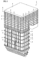
- FIG. 1 is a perspective view of a buckstay 1 installed around a furnace B.
- the buckstay 1 is disposed a predetermined distance apart from a furnace wall of the furnace B, and is connected with the furnace B by supports (not shown), thereby inhibiting deformation of the furnace B.
- the buckstay 1 itself is supported by suspension from, for example, a support structure K installed on the furnace B along with the furnace B.
- the buckstay 1 is made up of vertical buckstays 2 installed in a height direction of the furnace B, and horizontal buckstays 3 installed in a width direction of the furnace B.
- the horizontal buckstays 3 are disposed so as to surround the entire circumference of the furnace B when viewed from the top, and are installed in multiple steps in the height direction.
- the vertical buckstays 2 are installed between every step of the horizontal buckstays 3.
- the vertical buckstays 2 function as a spur for preventing the horizontal buckstays 3 from falling, in addition to functioning as the above-mentioned buckstays.
- the horizontal buckstays 3 intend to incline around the connections between the horizontal buckstays 3 and the supports and fall due to the own weight of each horizontal buckstay 3.
- the vertical buckstays 2 are installed between the horizontal buckstays 3 spaced apart from each other in the vertical direction, thereby preventing the horizontal buckstays 3 from falling.
- these vertical and horizontal buckstays 2 and 3 are formed of H-section steel.
- the vertical buckstays 2 are formed of H-section steel having a smaller cross-sectional area, compared to the horizontal buckstays 3.
- FIG. 2 is a side view of the vertical buckstay 2 and the horizontal buckstay 3, including the buckstay connecting system 10.
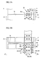
- FIG. 3A is a cross-sectional view taken along line A-A of FIG. 2
- FIG. 3B is a side view of an upper fixture part of a buckstay connecting system in an embodiment of the present invention.
- FIG. 4 is a cross-sectional view taken along line B-B of FIG. 3B .
- a posture of the horizontal buckstay 3 is configured such that its web 3a is horizontal, and its flanges 3b are arranged in a direction where they are separated from the furnace wall.
- a posture of the vertical buckstay 2 is configured such that its web 2a is vertical, and its flanges 2b are arranged in a direction where they are separated from the furnace wall.
- the buckstay connecting system 10 of the present embodiment includes a socket part 20, lower splice plates (insertion parts) 30, an upper fixture part 40, and an upper splice plate 50.
- the socket part 20 is configured so that the lower splice plates 30 are inserted thereinto, and is disposed between a lower end 2c of the vertical buckstay 2 and the horizontal buckstay 3.
- the socket part 20 has an upper end slightly separated from the lower end 2c of the vertical buckstay 2 and a lower end fixed to the web 3a of the horizontal buckstay 3 by welding. Further, a rib 3c is formed between the flanges 3b on the web 3a of the horizontal buckstay 3, and the socket part 20 is also firmly fixed to this rib 3c by welding. As shown in FIG.
- the socket part 20 has an H-shaped cross section having the same size as the vertical buckstay 2, and a posture of the socket part 20 is configured such that its web 20a is vertical and its flanges 20b are arranged in a direction where they are separated from the furnace wall, like the vertical buckstay 2.
- the socket part 20 and the vertical buckstay 2 are disposed in parallel in the vertical direction so as to overlap each other when viewed from the top.
- the web 20a of the socket part 20 is provided with two through-holes 20c, through which bolts can be inserted, in an upper portion thereof in parallel to the horizontal direction.
- each lower splice plate 30 is fixed to the lower portion of the vertical buckstay 2, and are inserted into the socket part 20 so as to be able to slide in the vertical direction. More particularly, in the preset embodiment, the lower splice plates 30 are each inserted into an area that is surrounded by the web 20a and the flanges 20b of the socket part 20. As shown in FIG. 3A , each lower splice plate 30 includes a central portion 30a, which is in contact with a wall surface of the web 20a of the socket part 20, and bent portions 30b, which are in contact with wall surfaces of the flanges 20b of the socket part 20, and is an approximately C-shaped plate member when viewed from the top.
- each lower splice plate 30 is fixed to the lower portion of the vertical buckstay 2 by two bolts 60. That is, the lower splice plates 30 are fixed to the lower portion of the vertical buckstay 2 by bolt-fastening.
- the lower splice plate 30 is provided with through-holes 30c, through which bolts are inserted, in a lower portion thereof.
- the two through-holes 30c are formed in parallel in the horizontal direction so as to overlap the through-holes 20c formed in the web 20a of the socket part 20.
- the through-holes 20c and the through-holes 30c overlap to insert the bolts and mount nuts, so that the lower splice plates 30 can be fastened to the socket part 20.
- the upper fixture part 40 is formed of H section steel having the same size as the socket part 20, and is fixed to a lower surface of the web 3a of the horizontal buckstay 3 by welding. Further, a rib 3d is formed between the flanges 3b on the lower surface of the web 3a of the horizontal buckstay 3. The upper fixture part 40 is also firmly fixed to this rib 3d by welding. The upper fixture part 40 is disposed so as to overlap the vertical buckstay 2 when viewed from the top, like the socket part 20.
- the upper splice plate 50 shown in FIGS. 3B and 4 is a plate member for connecting the upper portion of the vertical buckstay 2 with the upper fixture part 40.
- the upper fixture part 40 and the vertical buckstay 2 are fastened to the upper splice plate 50 by bolts 70, and thereby are connected to each other.
- the upper splice plate 50 includes two web connecting plates 50a for connecting the web 2a of the vertical buckstay 2 with the web 40a of the upper fixture part 40, and four flange connecting plates 50b for connecting the flanges 2b of the vertical buckstay 2 with the flanges 40b of the upper fixture part 40.
- the buckstay connecting system 10 of the present embodiment having this construction, when the lower splice plates 30 are not fastened to the socket part 20, the positional relationship of the height directions of the vertical buckstay 2 and the horizontal buckstay 3 varies when the furnace B is expanded or contracted in the height direction by, for example, thermal expansion. Even in this case, according to the buckstay connecting system 10 of the present embodiment, the lower splice plates 30 slide in the state where they are inserted into the socket part 20, so that it is possible to prevent stress from being applied to the vertical buckstay 2 or the horizontal buckstay 3.
- the horizontal buckstay 3 can inhibit such inclination.
- the vertical buckstay connecting system 10 of the present embodiment during construction of the thermal electric power plant, when the horizontal and vertical buckstays are installed around the furnace B, the lower splice plates 30 are fastened to the socket part 20, so that the vertical buckstay 2 and the horizontal buckstay 3 are firmly coupled. For this reason, the vertical buckstay 2 can receive at least part of a load caused by the horizontal buckstay 3 about to fall during the installation, and thus it is possible to reduce the construction materials of the conventional temporary construction materials, or it is possible to install the horizontal buckstay 3 and the vertical buckstay 2 without installing the conventional temporary construction materials.
- the lower splice plates 30, i.e. the vertical buckstay 2 can slide in the vertical direction with respect to the horizontal buckstay 3 by unfastening of the lower splice plates 30 and the socket part 20. Further, the horizontal buckstay 3 is prevented from falling by the contact between the lower splice plates 30 and the wall surfaces of the socket part 20.
- the lower splice plates 30 are separated from the vertical buckstay 2.
- the total length of the vertical buckstay 2 becomes short, and it is possible to dispose the socket part 20 between the vertical buckstay 2 and its lower horizontal buckstay 3.
- the vertical buckstay 2 does not interfere with the socket part 20, and it is possible to weld the socket part 20 to the horizontal buckstay 3 in advance in a factory.
- the buckstay connecting system 10 of the present embodiment it is possible to reduce the burden on the welding work required to connect the vertical buckstay 2 with the horizontal buckstay 3 and to reduce the construction materials required for the temporary construction materials for preventing the horizontal buckstay 3 from falling.
- the bolt insertion holes 30c and 20c are formed in the lower portions of the lower splice plates 30 and the socket part 20 in advance. These insertion holes are aligned, and the bolts are inserted and fixed through the insertion holes. As such, according to the buckstay connecting system 10 of the present embodiment, it is possible to fasten the lower splice plates 30 and the socket part 20 in a more simple way and to unfasten the lower splice plates 30 and the socket part 20 with ease.
- the upper portion of the vertical buckstay 2 and the horizontal buckstay 3 are fixed by the upper fixture part 40 and the upper splice plate 50 by bolt fastening.
- the upper portion of the vertical buckstay 2 and the horizontal buckstay 3 can be fixed without welding the upper portion of the vertical buckstay 2 and the horizontal buckstay 3.
- the vertical buckstay 2, the horizontal buckstay 3, the socket part 20, and the like have been described as being formed of H-section steel.
- the present invention is not limited to this construction, and thus the vertical buckstay 2, the horizontal buckstay 3, the socket part 20, and the like may have different shapes.
- the upper portion of the vertical buckstay 2 and the horizontal buckstay 3 have been described as being fixed by the upper fixture part 40 and the upper splice plate 50 by bolt fastening.
- the present invention is not limited to this construction, and thus the upper portion of the vertical buckstay 2 and the horizontal buckstay 3 may be fixed by welding.
- Example embodiments of the present invention have been described above. However, the present invention is not limited to these embodiments. Addition, omission, substitution, and other modifications to the construction within a scope that does not deviate from the gist of the present invention are also possible. The present invention is not limited by the description made above, and is limited only by the scope of the appended claims.
Landscapes
- Engineering & Computer Science (AREA)
- Physics & Mathematics (AREA)
- Thermal Sciences (AREA)
- Mechanical Engineering (AREA)
- General Engineering & Computer Science (AREA)
- Furnace Housings, Linings, Walls, And Ceilings (AREA)
- Furnace Charging Or Discharging (AREA)
- Agricultural Machines (AREA)
Abstract
Description
- The present invention relates to a buckstay connecting system, and more particularly, to a buckstay connecting system for connecting a vertical buckstay installed in a height direction of a furnace with a horizontal buckstay installed in a width direction of the furnace.
This application claims priority to and the benefits of Japanese Patent Application No.2009-243278 filed on October 22, 2009 - As is widely known, furnaces installed on, for example, thermal electric power plants have a furnace wall made up of a plurality of water pipes and fins interposed between the water pipes.
The furnace wall is supported in such a way that it is suspended from a building covering to build a furnace, and thus has weak stiffness. For this reason, in order to enhance the stiffness of the furnace wall and to inhibit the furnace from being greatly deformed by thermal expansion of the furnace wall or pressure variation in the furnace, a plurality of buckstays are disposed around the furnace.
These buckstays are made up of horizontal buckstays horizontally installed along the furnace wall around the furnace and vertical buckstays vertically installed along the furnace wall around the furnace. Each buckstay is formed of, for example, H-section steel. -
- [Patent Document 1] Japanese Patent Application Publication No.
2001-221404 - However, the buckstays prevent excessive deformation of the furnace, but fail to perfectly inhibit such deformation. As such, when the furnace is deformed by thermal expansion, this leads to displacement of the buckstays.
The buckstays are typically made up of vertical buckstays installed in a height direction of the furnace and horizontal buckstays installed in a width direction of the furnace. Although these vertical and horizontal buckstays are interconnected, the vertical buckstays are displaced in a vertical direction with respect to the horizontal buckstays due to the above-mentioned deformation of the furnace. For this reason, the vertical buckstays are connected to be able to slide in the vertical direction with respect to the horizontal buckstays. - In greater detail, the horizontal buckstays are installed in multiple steps in the height direction of the furnace, and the vertical buckstays are installed between the multiple steps. Each vertical buckstay is welded and fixed to the horizontal buckstay disposed just above an upper end thereof and is inserted into a box-shaped socket part installed on the horizontal buckstay disposed just below a lower portion including a lower end thereof. Here, the lower end of the vertical buckstay is not fixed to the horizontal buckstay but is only inserted into the socket part. Thus, when the vertical buckstay is displaced in the vertical direction with respect to the horizontal buckstay, the vertical buckstay slides in the vertical direction with respect to the horizontal buckstay.
- In this manner, the vertical buckstay slides in the vertical direction with respect to the horizontal buckstay, but its lower end is always located in the socket part. As such, the vertical buckstay can always come into contact with the surface of an inner wall of the socket part. Thereby, the horizontal buckstay is prevented from falling.
- During construction of thermal electric power plants, or the like, when these buckstays are installed around the furnace, the horizontal buckstays are first installed, and then the vertical buckstays are installed between the horizontal buckstays. However, since it is necessary to inhibit the falling of the horizontal buckstays until the upper ends of the vertical buckstays functioning to prevent the horizontal buckstays from falling are welded to their upper horizontal buckstays and the lower portion of the vertical buckstays are inserted into the socket parts installed on their lower horizontal buckstays, temporary construction materials supporting the horizontal buckstays are installed around the furnace. Since these temporary construction materials need to support all the horizontal buckstays ready to fall in a horizontal state, too many construction materials are required. Further, after all of the vertical buckstays are installed, all of the temporary construction materials need to be removed. As such, the temporary construction materials for supporting the horizontal buckstays are attributed to increasing the period and cost of construction when constructing, for example, the thermal electric power plant.
- Further, when the vertical buckstays are installed in a construction field, the upper ends of the vertical buckstays are welded to the horizontal buckstays, and then socket parts are welded to the horizontal buckstays so as to surround the lower portion of the vertical buckstays. For this reason, the welding work is great in the construction field, which leads to increasing the period and cost of construction.
- The present invention has been made in view of the above-described circumstances, and an object of the invention is to provide a buckstay connecting system, which attempts to reduce a burden on welding work required to connect a vertical buckstay with a horizontal buckstay and to reduce construction materials required for temporary construction materials for preventing the horizontal buckstay from falling.
- According to a first aspect of the present invention, a buckstay connecting system is provided for connecting a vertical buckstay installed in a height direction of a furnace with a horizontal buckstay installed in a width direction of the furnace. The buckstay connecting system includes: a socket part that is fixed to the horizontal buckstay being separated from a lower end of the vertical buckstay between the lower end of the vertical buckstay and the horizontal buckstay; and an insertion part that is fixed to a lower portion of the vertical buckstay, is inserted into the socket part so as to be able to slide in a vertical direction, inhibits an inclination of the horizontal buckstay with respect to a horizontal direction of the furnace and is allowed to be fastened to the socket part.
- According to a second aspect of the present invention, the socket part and a lower portion of the insertion part is provided with bolt insertion holes, and the socket part and the insertion part may be fastened by aligning these insertion holes, and inserting and fixing bolts through the insertion holes.
- According to a third aspect of the present invention, the insertion part may be fixed to the lower portion of the vertical buckstay by bolt fastening.
- According to a fourth aspect of the present invention, the horizontal buckstay may be fixed to an upper portion of the vertical buckstay by bolt fastening.
- According to a fifth aspect of the present invention, the vertical buckstay and the socket part may have H-shaped cross sections of the same size, have an H shape when viewed from the top, and be superposed when viewed from the top.
- According to the present invention, the insertion part, which is fixed to the lower portion of the vertical buckstay and is inserted into the socket part so as to be able to slide in a vertical direction, can be fastened to the socket part. As such, when the horizontal and vertical buckstays are installed, the insertion part is fastened to the socket part, so that the vertical buckstay and the horizontal buckstay are firmly coupled. For this reason, the vertical buckstay can receive at least a part of a load caused by the horizontal buckstay ready to fall, and thus it is possible to reduce construction materials of conventional temporary construction materials, or to install the horizontal buckstay and the vertical buckstay without installing the conventional temporary construction materials.
Further, when the installation of the horizontal buckstay and the vertical buckstay is completed, and the horizontal buckstay can be supported by, for example, the furnace wall, the insertion part, i.e. the vertical buckstay, can slide in the vertical direction with respect to the horizontal buckstay by unfastening of the insertion part and the socket part. Further, the horizontal buckstay is prevented from falling by the contact between the insertion part and inner walls of the socket part. - Further, according to the present invention, the insertion part is separated from the vertical buckstay. Thereby, the total length of the vertical buckstay becomes short, and it is possible to dispose the socket part between the vertical buckstay and its lower horizontal buckstay. As such, when the horizontal buckstay and the vertical buckstay are installed, the vertical buckstay does not interfere with the socket part, and it is possible to weld the socket part to the horizontal buckstay in advance in a factory. Thus, according to the present embodiment, it is possible to reduce a burden on welding work in a construction field.
- As described above, according to the present invention, it is possible to reduce the burden on the welding work required to connect the vertical buckstay with the horizontal buckstay and to reduce the construction materials required for the temporary construction materials for preventing the horizontal buckstay from falling.
-
-
FIG. 1 is a perspective view of a buckstay installed around a furnace. -
FIG. 2 is a side view of a vertical buckstay and a horizontal buckstay, including a buckstay connecting system according to one embodiment of the present invention. -
FIG. 3A is a cross-sectional view taken along line A-A ofFIG. 2 . -
FIG. 3B is a side view of an upper fixture part of a buckstay connecting system according to one embodiment of the present invention. -
FIG. 4 is a cross-sectional view taken along line B-B ofFIG. 3B . - Hereinafter, an embodiment of a buckstay connecting system related to the present invention will be described with reference to the accompanying drawings. Further, in the drawings, the scale of each member is appropriately modified so as to make the size of each member recognizable.
-
FIG. 1 is a perspective view of abuckstay 1 installed around a furnace B. Thebuckstay 1 is disposed a predetermined distance apart from a furnace wall of the furnace B, and is connected with the furnace B by supports (not shown), thereby inhibiting deformation of the furnace B. Thebuckstay 1 itself is supported by suspension from, for example, a support structure K installed on the furnace B along with the furnace B. - As shown in
FIG. 1 , thebuckstay 1 is made up ofvertical buckstays 2 installed in a height direction of the furnace B, andhorizontal buckstays 3 installed in a width direction of the furnace B.
Thehorizontal buckstays 3 are disposed so as to surround the entire circumference of the furnace B when viewed from the top, and are installed in multiple steps in the height direction.
Thevertical buckstays 2 are installed between every step of thehorizontal buckstays 3. Thevertical buckstays 2 function as a spur for preventing thehorizontal buckstays 3 from falling, in addition to functioning as the above-mentioned buckstays. In greater detail, since sides of thehorizontal buckstays 3 near the furnace wall of the furnace B are connected to the furnace wall of the furnace B by the supports (not shown), thehorizontal buckstays 3 intend to incline around the connections between thehorizontal buckstays 3 and the supports and fall due to the own weight of eachhorizontal buckstay 3. In this regard, thevertical buckstays 2 are installed between thehorizontal buckstays 3 spaced apart from each other in the vertical direction, thereby preventing thehorizontal buckstays 3 from falling.
Further, in the present embodiment, these vertical and horizontal buckstays 2 and 3 are formed of H-section steel. Furthermore, thevertical buckstays 2 are formed of H-section steel having a smaller cross-sectional area, compared to thehorizontal buckstays 3. - The
buckstay connecting system 10 of the present embodiment connects the above-mentioned vertical and horizontal buckstays 2 and 3.
FIG. 2 is a side view of thevertical buckstay 2 and thehorizontal buckstay 3, including thebuckstay connecting system 10. Further,FIG. 3A is a cross-sectional view taken along line A-A ofFIG. 2 , andFIG. 3B is a side view of an upper fixture part of a buckstay connecting system in an embodiment of the present invention.FIG. 4 is a cross-sectional view taken along line B-B ofFIG. 3B .
In the present embodiment, as shown inFIG. 2 , a posture of thehorizontal buckstay 3 is configured such that itsweb 3a is horizontal, and itsflanges 3b are arranged in a direction where they are separated from the furnace wall. Further, a posture of thevertical buckstay 2 is configured such that itsweb 2a is vertical, and itsflanges 2b are arranged in a direction where they are separated from the furnace wall. - As shown in
FIGS. 2 through 4 , thebuckstay connecting system 10 of the present embodiment includes asocket part 20, lower splice plates (insertion parts) 30, anupper fixture part 40, and anupper splice plate 50. - The
socket part 20 is configured so that thelower splice plates 30 are inserted thereinto, and is disposed between alower end 2c of thevertical buckstay 2 and thehorizontal buckstay 3. Thesocket part 20 has an upper end slightly separated from thelower end 2c of thevertical buckstay 2 and a lower end fixed to theweb 3a of thehorizontal buckstay 3 by welding. Further, arib 3c is formed between theflanges 3b on theweb 3a of thehorizontal buckstay 3, and thesocket part 20 is also firmly fixed to thisrib 3c by welding.
As shown inFIG. 3A , thesocket part 20 has an H-shaped cross section having the same size as thevertical buckstay 2, and a posture of thesocket part 20 is configured such that itsweb 20a is vertical and itsflanges 20b are arranged in a direction where they are separated from the furnace wall, like thevertical buckstay 2. Thesocket part 20 and thevertical buckstay 2 are disposed in parallel in the vertical direction so as to overlap each other when viewed from the top.
Further, theweb 20a of thesocket part 20 is provided with two through-holes 20c, through which bolts can be inserted, in an upper portion thereof in parallel to the horizontal direction. - The
lower splice plates 30 are fixed to the lower portion of thevertical buckstay 2, and are inserted into thesocket part 20 so as to be able to slide in the vertical direction. More particularly, in the preset embodiment, thelower splice plates 30 are each inserted into an area that is surrounded by theweb 20a and theflanges 20b of thesocket part 20.
As shown inFIG. 3A , eachlower splice plate 30 includes acentral portion 30a, which is in contact with a wall surface of theweb 20a of thesocket part 20, andbent portions 30b, which are in contact with wall surfaces of theflanges 20b of thesocket part 20, and is an approximately C-shaped plate member when viewed from the top. Thelower splice plates 30 are installed on opposite sides of thesocket part 20, and thus the total of twolower splice plates 30 are installed.
Further, eachlower splice plate 30 is fixed to the lower portion of thevertical buckstay 2 by twobolts 60. That is, thelower splice plates 30 are fixed to the lower portion of thevertical buckstay 2 by bolt-fastening. - In the
buckstay connecting system 10 of the present embodiment, thelower splice plate 30 is provided with through-holes 30c, through which bolts are inserted, in a lower portion thereof. Like the through-holes 20c, the two through-holes 30c are formed in parallel in the horizontal direction so as to overlap the through-holes 20c formed in theweb 20a of thesocket part 20.
In other words, in thebuckstay connecting system 10 of the present embodiment, the through-holes 20c and the through-holes 30c overlap to insert the bolts and mount nuts, so that thelower splice plates 30 can be fastened to thesocket part 20. - As shown in
FIGS. 3B and4 , theupper fixture part 40 is formed of H section steel having the same size as thesocket part 20, and is fixed to a lower surface of theweb 3a of thehorizontal buckstay 3 by welding. Further, arib 3d is formed between theflanges 3b on the lower surface of theweb 3a of thehorizontal buckstay 3. Theupper fixture part 40 is also firmly fixed to thisrib 3d by welding. Theupper fixture part 40 is disposed so as to overlap thevertical buckstay 2 when viewed from the top, like thesocket part 20. - The
upper splice plate 50 shown inFIGS. 3B and4 is a plate member for connecting the upper portion of thevertical buckstay 2 with theupper fixture part 40. Theupper fixture part 40 and thevertical buckstay 2 are fastened to theupper splice plate 50 bybolts 70, and thereby are connected to each other.
Further, as shown inFIG. 4 , theupper splice plate 50 includes twoweb connecting plates 50a for connecting theweb 2a of thevertical buckstay 2 with theweb 40a of theupper fixture part 40, and fourflange connecting plates 50b for connecting theflanges 2b of thevertical buckstay 2 with theflanges 40b of theupper fixture part 40. - In the
buckstay connecting system 10 of the present embodiment having this construction, when thelower splice plates 30 are not fastened to thesocket part 20, the positional relationship of the height directions of thevertical buckstay 2 and thehorizontal buckstay 3 varies when the furnace B is expanded or contracted in the height direction by, for example, thermal expansion. Even in this case, according to thebuckstay connecting system 10 of the present embodiment, thelower splice plates 30 slide in the state where they are inserted into thesocket part 20, so that it is possible to prevent stress from being applied to thevertical buckstay 2 or thehorizontal buckstay 3.
Further, since thebent portions 30b of thelower splice plates 30 are in contact with the wall surface of theflanges 20b of thesocket part 20, even when theflange 3b of thehorizontal buckstay 3 on the side separated from the furnace wall is about to be inclined downwards, thehorizontal buckstay 3 can inhibit such inclination. - According to the
buckstay connecting system 10 of the present embodiment, during construction of the thermal electric power plant, when the horizontal and vertical buckstays are installed around the furnace B, thelower splice plates 30 are fastened to thesocket part 20, so that thevertical buckstay 2 and thehorizontal buckstay 3 are firmly coupled. For this reason, thevertical buckstay 2 can receive at least part of a load caused by thehorizontal buckstay 3 about to fall during the installation, and thus it is possible to reduce the construction materials of the conventional temporary construction materials, or it is possible to install thehorizontal buckstay 3 and thevertical buckstay 2 without installing the conventional temporary construction materials.
Further, when the installation of thehorizontal buckstay 3 and thevertical buckstay 2 is completed, and thehorizontal buckstay 3 can be supported by, for example, the furnace wall, thelower splice plates 30, i.e. thevertical buckstay 2, can slide in the vertical direction with respect to thehorizontal buckstay 3 by unfastening of thelower splice plates 30 and thesocket part 20. Further, thehorizontal buckstay 3 is prevented from falling by the contact between thelower splice plates 30 and the wall surfaces of thesocket part 20. - Further, according to the
buckstay connecting system 10 of the present embodiment, thelower splice plates 30 are separated from thevertical buckstay 2. Thereby, the total length of thevertical buckstay 2 becomes short, and it is possible to dispose thesocket part 20 between thevertical buckstay 2 and its lowerhorizontal buckstay 3. As such, when thehorizontal buckstay 3 and thevertical buckstay 2 are installed, thevertical buckstay 2 does not interfere with thesocket part 20, and it is possible to weld thesocket part 20 to thehorizontal buckstay 3 in advance in a factory. Thus, according to thebuckstay connecting system 10 of the present embodiment, it is possible to reduce a burden on welding work in the construction field. - As described above, according to the
buckstay connecting system 10 of the present embodiment, it is possible to reduce the burden on the welding work required to connect thevertical buckstay 2 with thehorizontal buckstay 3 and to reduce the construction materials required for the temporary construction materials for preventing thehorizontal buckstay 3 from falling. - Further, according to the
buckstay connecting system 10 of the present embodiment, thebolt insertion holes lower splice plates 30 and thesocket part 20 in advance. These insertion holes are aligned, and the bolts are inserted and fixed through the insertion holes.
As such, according to thebuckstay connecting system 10 of the present embodiment, it is possible to fasten thelower splice plates 30 and thesocket part 20 in a more simple way and to unfasten thelower splice plates 30 and thesocket part 20 with ease. - Further, in the
buckstay connecting system 10 of the present embodiment, the upper portion of thevertical buckstay 2 and thehorizontal buckstay 3 are fixed by theupper fixture part 40 and theupper splice plate 50 by bolt fastening.
As such, the upper portion of thevertical buckstay 2 and thehorizontal buckstay 3 can be fixed without welding the upper portion of thevertical buckstay 2 and thehorizontal buckstay 3. Thus, it is possible to further reduce the burden on the welding work required to connect thevertical buckstay 2 with thehorizontal buckstay 3. - Embodiments of the present invention have been described with reference to the drawings. However, the present invention is not limited to these embodiments. The various shapes and combinations of each composite member shown in the embodiment described above refer to only a single example, and may be altered in various ways based on design requirements and so forth within a scope that does not deviate from the subject matter of the present invention.
- For example, in the above-mentioned embodiment, the
vertical buckstay 2, thehorizontal buckstay 3, thesocket part 20, and the like have been described as being formed of H-section steel.
However, the present invention is not limited to this construction, and thus thevertical buckstay 2, thehorizontal buckstay 3, thesocket part 20, and the like may have different shapes. - Further, in the above-mentioned embodiment, the upper portion of the
vertical buckstay 2 and thehorizontal buckstay 3 have been described as being fixed by theupper fixture part 40 and theupper splice plate 50 by bolt fastening.
However, the present invention is not limited to this construction, and thus the upper portion of thevertical buckstay 2 and thehorizontal buckstay 3 may be fixed by welding. - Example embodiments of the present invention have been described above. However, the present invention is not limited to these embodiments. Addition, omission, substitution, and other modifications to the construction within a scope that does not deviate from the gist of the present invention are also possible. The present invention is not limited by the description made above, and is limited only by the scope of the appended claims.
Claims (5)
- A buckstay connecting system for connecting a vertical buckstay installed in a height direction of a furnace with a horizontal buckstay installed in a width direction of the furnace, the buckstay connecting system comprising:a socket part that is fixed to the horizontal buckstay being separated from a lower end of the vertical buckstay between the lower end of the vertical buckstay and the horizontal buckstay; andan insertion part that is fixed to a lower portion of the vertical buckstay, is inserted into the socket part so as to be able to slide in a vertical direction, inhibits an inclination of the horizontal buckstay with respect to a horizontal direction of the furnace, and is allowed to be fastened to the socket part.
- The buckstay connecting system according to claim 1, wherein the socket part and a lower portion of the insertion part is provided with bolt insertion holes, and the socket part and the insertion part may be fastened by aligning these insertion holes, and inserting and fixing bolts through the insertion holes.
- The buckstay connecting system according to claim 1, wherein the insertion part is fixed to the lower portion of the vertical buckstay by bolt fastening.
- The buckstay connecting system according to claim 1, wherein the horizontal buckstay is fixed to an upper portion of the vertical buckstay by bolt fastening.
- The buckstay connecting system according to claim 1, wherein the vertical buckstay and the socket part have H-shaped cross sections, which are the same size, have an H shape when viewed from the top and are superposed when viewed from the top.
Applications Claiming Priority (1)
| Application Number | Priority Date | Filing Date | Title |
|---|---|---|---|
| JP2009243278A JP5387324B2 (en) | 2009-10-22 | 2009-10-22 | Backstay coupling mechanism |
Publications (3)
| Publication Number | Publication Date |
|---|---|
| EP2388518A2 true EP2388518A2 (en) | 2011-11-23 |
| EP2388518A3 EP2388518A3 (en) | 2014-11-12 |
| EP2388518B1 EP2388518B1 (en) | 2016-12-07 |
Family
ID=43897305
Family Applications (1)
| Application Number | Title | Priority Date | Filing Date |
|---|---|---|---|
| EP10251820.6A Not-in-force EP2388518B1 (en) | 2009-10-22 | 2010-10-19 | Buckstay connecting system |
Country Status (3)
| Country | Link |
|---|---|
| US (1) | US8939112B2 (en) |
| EP (1) | EP2388518B1 (en) |
| JP (1) | JP5387324B2 (en) |
Families Citing this family (3)
| Publication number | Priority date | Publication date | Assignee | Title |
|---|---|---|---|---|
| EP2026000A1 (en) * | 2007-08-10 | 2009-02-18 | Siemens Aktiengesellschaft | Steam generator |
| JP7115094B2 (en) * | 2018-07-20 | 2022-08-09 | 富士通株式会社 | Information processing device, control program, control method, and monitoring device |
| RU2729564C1 (en) * | 2019-11-29 | 2020-08-07 | Открытое акционерное общество "Таганрогский котлостроительный завод "Красный котельщик" (ОАО ТКЗ "Красный котельщик") | Boiler membrane wall |
Citations (2)
| Publication number | Priority date | Publication date | Assignee | Title |
|---|---|---|---|---|
| JP2001221404A (en) | 2000-02-03 | 2001-08-17 | Mitsubishi Heavy Ind Ltd | Backstay holder structure of boiler |
| JP2009243278A (en) | 2008-03-28 | 2009-10-22 | Hitachi Ltd | Engine system |
Family Cites Families (14)
| Publication number | Priority date | Publication date | Assignee | Title |
|---|---|---|---|---|
| US2583599A (en) * | 1946-03-14 | 1952-01-29 | Babcock & Wilcox Co | Boiler and furnace wall support |
| US2773487A (en) | 1952-08-27 | 1956-12-11 | Combustion Eng | Furnace having walls organized for cubical expansion |
| US3301225A (en) * | 1965-03-29 | 1967-01-31 | Babcock & Wilcox Co | Vapor generator wall buckstay arrangement |
| FR1452490A (en) * | 1965-11-02 | 1966-02-25 | Combustion Eng | Improvements made to reinforcements for hearth walls |
| US3814063A (en) * | 1973-07-13 | 1974-06-04 | Babcock & Wilcox Ltd | Support of tube walls |
| JPH0194704A (en) | 1987-10-07 | 1989-04-13 | Seiko Epson Corp | Oscillation circuit |
| JPH0194704U (en) * | 1987-12-07 | 1989-06-22 | ||
| JPH02140108A (en) | 1988-11-21 | 1990-05-29 | Nishikawa Kasei Kk | Manufacture for different hardness cushion body |
| JPH02140108U (en) * | 1989-04-28 | 1990-11-22 | ||
| US5317993A (en) * | 1992-12-29 | 1994-06-07 | Combustion Engineering, Inc. | Vertical buckstay/leveler attachment to a horizontal buckstay |
| US5865149A (en) * | 1996-12-23 | 1999-02-02 | Combustion Engineering, Inc. | Buckstay corner assembly with buckstay extension plates for a boiler |
| JP3825207B2 (en) * | 1999-07-23 | 2006-09-27 | 三菱重工業株式会社 | Back-stillless structure of exhaust gas boiler casing |
| JP2002257303A (en) * | 2001-03-02 | 2002-09-11 | Takuma Co Ltd | Support structure for intermediate support type water tube boiler |
| US8333170B2 (en) * | 2008-12-23 | 2012-12-18 | Doozan Babcock Energy America, LLC | Buckstay system |
-
2009
- 2009-10-22 JP JP2009243278A patent/JP5387324B2/en active Active
-
2010
- 2010-10-19 US US12/907,423 patent/US8939112B2/en active Active
- 2010-10-19 EP EP10251820.6A patent/EP2388518B1/en not_active Not-in-force
Patent Citations (2)
| Publication number | Priority date | Publication date | Assignee | Title |
|---|---|---|---|---|
| JP2001221404A (en) | 2000-02-03 | 2001-08-17 | Mitsubishi Heavy Ind Ltd | Backstay holder structure of boiler |
| JP2009243278A (en) | 2008-03-28 | 2009-10-22 | Hitachi Ltd | Engine system |
Also Published As
| Publication number | Publication date |
|---|---|
| US20110094455A1 (en) | 2011-04-28 |
| JP5387324B2 (en) | 2014-01-15 |
| JP2011089700A (en) | 2011-05-06 |
| US8939112B2 (en) | 2015-01-27 |
| EP2388518A3 (en) | 2014-11-12 |
| EP2388518B1 (en) | 2016-12-07 |
Similar Documents
| Publication | Publication Date | Title |
|---|---|---|
| EP3187761B1 (en) | Fastening-type pipe supporting apparatus for curved pipe | |
| CN101263301B (en) | Method of mounting elements inside a wind generator tower | |
| KR101354857B1 (en) | Strut having angle pipe section symmetrical with neural axis | |
| WO2013094780A1 (en) | Plate welding-type anchor channel and method for manufacturing same | |
| EP2388518B1 (en) | Buckstay connecting system | |
| JP6888970B2 (en) | Construction method of joint structure between column and beam and joint structure between column and beam | |
| CN112408150B (en) | Guide rail bracket assembly | |
| KR20150055519A (en) | Brick support apparatus and construction method of brick wall using the same | |
| KR101912226B1 (en) | H-Beam Reinforcement Apparatus | |
| KR101538579B1 (en) | Construction method of steel frame structure | |
| CN104471163A (en) | Tower structure and method of assembling | |
| WO2007068802A2 (en) | Method of and apparatus for supporting walls of a power boiler | |
| KR101526141B1 (en) | Buckstay system | |
| KR101925578B1 (en) | Brick wall support apparatus | |
| RU161408U1 (en) | CABLE TRAY CONNECTOR | |
| JP5008891B2 (en) | Solar panel installation structure | |
| EP2174902A1 (en) | Elevator guide rail fixing brackets | |
| JP4543997B2 (en) | Joint structure of base material and connecting material | |
| US20130272485A1 (en) | Nuclear reactor vessel support structure and construction method of nuclear reactor vessel support structure | |
| KR101954789B1 (en) | Platform fixed Wind Turbine Plant with Pipe. | |
| KR200440004Y1 (en) | Rescuer connector for jack support | |
| KR102060885B1 (en) | Assembly type handrail | |
| RU2837723C1 (en) | Cable penetration | |
| CN214280787U (en) | Subway wire casing assembly structure and pendant | |
| EP4474579A1 (en) | Internal platform support structure for an offshore foundation structure |
Legal Events
| Date | Code | Title | Description |
|---|---|---|---|
| 17P | Request for examination filed |
Effective date: 20110209 |
|
| AK | Designated contracting states |
Kind code of ref document: A2 Designated state(s): AL AT BE BG CH CY CZ DE DK EE ES FI FR GB GR HR HU IE IS IT LI LT LU LV MC MK MT NL NO PL PT RO RS SE SI SK SM TR |
|
| AX | Request for extension of the european patent |
Extension state: BA ME |
|
| PUAI | Public reference made under article 153(3) epc to a published international application that has entered the european phase |
Free format text: ORIGINAL CODE: 0009012 |
|
| PUAL | Search report despatched |
Free format text: ORIGINAL CODE: 0009013 |
|
| AK | Designated contracting states |
Kind code of ref document: A3 Designated state(s): AL AT BE BG CH CY CZ DE DK EE ES FI FR GB GR HR HU IE IS IT LI LT LU LV MC MK MT NL NO PL PT RO RS SE SI SK SM TR |
|
| AX | Request for extension of the european patent |
Extension state: BA ME |
|
| RIC1 | Information provided on ipc code assigned before grant |
Ipc: F22B 37/20 20060101AFI20141009BHEP Ipc: F22B 37/24 20060101ALI20141009BHEP Ipc: F22B 21/00 20060101ALI20141009BHEP |
|
| RBV | Designated contracting states (corrected) |
Designated state(s): AL AT BE BG CH CY CZ DE DK EE ES FI FR GB GR HR HU IE IS IT LI LT LU LV MC MK MT NL NO PL PT RO RS SE SI SK SM TR |
|
| GRAP | Despatch of communication of intention to grant a patent |
Free format text: ORIGINAL CODE: EPIDOSNIGR1 |
|
| RIC1 | Information provided on ipc code assigned before grant |
Ipc: F22B 21/00 20060101ALI20160519BHEP Ipc: F22B 37/24 20060101ALI20160519BHEP Ipc: F22B 37/20 20060101AFI20160519BHEP |
|
| INTG | Intention to grant announced |
Effective date: 20160617 |
|
| GRAS | Grant fee paid |
Free format text: ORIGINAL CODE: EPIDOSNIGR3 |
|
| GRAA | (expected) grant |
Free format text: ORIGINAL CODE: 0009210 |
|
| AK | Designated contracting states |
Kind code of ref document: B1 Designated state(s): AL AT BE BG CH CY CZ DE DK EE ES FI FR GB GR HR HU IE IS IT LI LT LU LV MC MK MT NL NO PL PT RO RS SE SI SK SM TR |
|
| REG | Reference to a national code |
Ref country code: GB Ref legal event code: FG4D |
|
| REG | Reference to a national code |
Ref country code: CH Ref legal event code: EP Ref country code: AT Ref legal event code: REF Ref document number: 852071 Country of ref document: AT Kind code of ref document: T Effective date: 20161215 |
|
| REG | Reference to a national code |
Ref country code: IE Ref legal event code: FG4D |
|
| REG | Reference to a national code |
Ref country code: DE Ref legal event code: R096 Ref document number: 602010038591 Country of ref document: DE |
|
| PG25 | Lapsed in a contracting state [announced via postgrant information from national office to epo] |
Ref country code: LV Free format text: LAPSE BECAUSE OF FAILURE TO SUBMIT A TRANSLATION OF THE DESCRIPTION OR TO PAY THE FEE WITHIN THE PRESCRIBED TIME-LIMIT Effective date: 20161207 |
|
| REG | Reference to a national code |
Ref country code: LT Ref legal event code: MG4D |
|
| REG | Reference to a national code |
Ref country code: NL Ref legal event code: MP Effective date: 20161207 |
|
| PG25 | Lapsed in a contracting state [announced via postgrant information from national office to epo] |
Ref country code: NO Free format text: LAPSE BECAUSE OF FAILURE TO SUBMIT A TRANSLATION OF THE DESCRIPTION OR TO PAY THE FEE WITHIN THE PRESCRIBED TIME-LIMIT Effective date: 20170307 Ref country code: SE Free format text: LAPSE BECAUSE OF FAILURE TO SUBMIT A TRANSLATION OF THE DESCRIPTION OR TO PAY THE FEE WITHIN THE PRESCRIBED TIME-LIMIT Effective date: 20161207 Ref country code: GR Free format text: LAPSE BECAUSE OF FAILURE TO SUBMIT A TRANSLATION OF THE DESCRIPTION OR TO PAY THE FEE WITHIN THE PRESCRIBED TIME-LIMIT Effective date: 20170308 Ref country code: LT Free format text: LAPSE BECAUSE OF FAILURE TO SUBMIT A TRANSLATION OF THE DESCRIPTION OR TO PAY THE FEE WITHIN THE PRESCRIBED TIME-LIMIT Effective date: 20161207 |
|
| REG | Reference to a national code |
Ref country code: AT Ref legal event code: MK05 Ref document number: 852071 Country of ref document: AT Kind code of ref document: T Effective date: 20161207 |
|
| PG25 | Lapsed in a contracting state [announced via postgrant information from national office to epo] |
Ref country code: FI Free format text: LAPSE BECAUSE OF FAILURE TO SUBMIT A TRANSLATION OF THE DESCRIPTION OR TO PAY THE FEE WITHIN THE PRESCRIBED TIME-LIMIT Effective date: 20161207 Ref country code: RS Free format text: LAPSE BECAUSE OF FAILURE TO SUBMIT A TRANSLATION OF THE DESCRIPTION OR TO PAY THE FEE WITHIN THE PRESCRIBED TIME-LIMIT Effective date: 20161207 Ref country code: ES Free format text: LAPSE BECAUSE OF FAILURE TO SUBMIT A TRANSLATION OF THE DESCRIPTION OR TO PAY THE FEE WITHIN THE PRESCRIBED TIME-LIMIT Effective date: 20161207 Ref country code: HR Free format text: LAPSE BECAUSE OF FAILURE TO SUBMIT A TRANSLATION OF THE DESCRIPTION OR TO PAY THE FEE WITHIN THE PRESCRIBED TIME-LIMIT Effective date: 20161207 |
|
| PG25 | Lapsed in a contracting state [announced via postgrant information from national office to epo] |
Ref country code: NL Free format text: LAPSE BECAUSE OF FAILURE TO SUBMIT A TRANSLATION OF THE DESCRIPTION OR TO PAY THE FEE WITHIN THE PRESCRIBED TIME-LIMIT Effective date: 20161207 |
|
| PG25 | Lapsed in a contracting state [announced via postgrant information from national office to epo] |
Ref country code: EE Free format text: LAPSE BECAUSE OF FAILURE TO SUBMIT A TRANSLATION OF THE DESCRIPTION OR TO PAY THE FEE WITHIN THE PRESCRIBED TIME-LIMIT Effective date: 20161207 Ref country code: SK Free format text: LAPSE BECAUSE OF FAILURE TO SUBMIT A TRANSLATION OF THE DESCRIPTION OR TO PAY THE FEE WITHIN THE PRESCRIBED TIME-LIMIT Effective date: 20161207 Ref country code: CZ Free format text: LAPSE BECAUSE OF FAILURE TO SUBMIT A TRANSLATION OF THE DESCRIPTION OR TO PAY THE FEE WITHIN THE PRESCRIBED TIME-LIMIT Effective date: 20161207 Ref country code: RO Free format text: LAPSE BECAUSE OF FAILURE TO SUBMIT A TRANSLATION OF THE DESCRIPTION OR TO PAY THE FEE WITHIN THE PRESCRIBED TIME-LIMIT Effective date: 20161207 Ref country code: IS Free format text: LAPSE BECAUSE OF FAILURE TO SUBMIT A TRANSLATION OF THE DESCRIPTION OR TO PAY THE FEE WITHIN THE PRESCRIBED TIME-LIMIT Effective date: 20170407 |
|
| PG25 | Lapsed in a contracting state [announced via postgrant information from national office to epo] |
Ref country code: PL Free format text: LAPSE BECAUSE OF FAILURE TO SUBMIT A TRANSLATION OF THE DESCRIPTION OR TO PAY THE FEE WITHIN THE PRESCRIBED TIME-LIMIT Effective date: 20161207 Ref country code: PT Free format text: LAPSE BECAUSE OF FAILURE TO SUBMIT A TRANSLATION OF THE DESCRIPTION OR TO PAY THE FEE WITHIN THE PRESCRIBED TIME-LIMIT Effective date: 20170407 Ref country code: BG Free format text: LAPSE BECAUSE OF FAILURE TO SUBMIT A TRANSLATION OF THE DESCRIPTION OR TO PAY THE FEE WITHIN THE PRESCRIBED TIME-LIMIT Effective date: 20170307 Ref country code: SM Free format text: LAPSE BECAUSE OF FAILURE TO SUBMIT A TRANSLATION OF THE DESCRIPTION OR TO PAY THE FEE WITHIN THE PRESCRIBED TIME-LIMIT Effective date: 20161207 Ref country code: IT Free format text: LAPSE BECAUSE OF FAILURE TO SUBMIT A TRANSLATION OF THE DESCRIPTION OR TO PAY THE FEE WITHIN THE PRESCRIBED TIME-LIMIT Effective date: 20161207 Ref country code: AT Free format text: LAPSE BECAUSE OF FAILURE TO SUBMIT A TRANSLATION OF THE DESCRIPTION OR TO PAY THE FEE WITHIN THE PRESCRIBED TIME-LIMIT Effective date: 20161207 Ref country code: BE Free format text: LAPSE BECAUSE OF FAILURE TO SUBMIT A TRANSLATION OF THE DESCRIPTION OR TO PAY THE FEE WITHIN THE PRESCRIBED TIME-LIMIT Effective date: 20161207 |
|
| REG | Reference to a national code |
Ref country code: DE Ref legal event code: R097 Ref document number: 602010038591 Country of ref document: DE |
|
| PLBE | No opposition filed within time limit |
Free format text: ORIGINAL CODE: 0009261 |
|
| STAA | Information on the status of an ep patent application or granted ep patent |
Free format text: STATUS: NO OPPOSITION FILED WITHIN TIME LIMIT |
|
| 26N | No opposition filed |
Effective date: 20170908 |
|
| PG25 | Lapsed in a contracting state [announced via postgrant information from national office to epo] |
Ref country code: DK Free format text: LAPSE BECAUSE OF FAILURE TO SUBMIT A TRANSLATION OF THE DESCRIPTION OR TO PAY THE FEE WITHIN THE PRESCRIBED TIME-LIMIT Effective date: 20161207 Ref country code: SI Free format text: LAPSE BECAUSE OF FAILURE TO SUBMIT A TRANSLATION OF THE DESCRIPTION OR TO PAY THE FEE WITHIN THE PRESCRIBED TIME-LIMIT Effective date: 20161207 |
|
| PGFP | Annual fee paid to national office [announced via postgrant information from national office to epo] |
Ref country code: DE Payment date: 20171011 Year of fee payment: 8 |
|
| PG25 | Lapsed in a contracting state [announced via postgrant information from national office to epo] |
Ref country code: MC Free format text: LAPSE BECAUSE OF FAILURE TO SUBMIT A TRANSLATION OF THE DESCRIPTION OR TO PAY THE FEE WITHIN THE PRESCRIBED TIME-LIMIT Effective date: 20161207 |
|
| REG | Reference to a national code |
Ref country code: CH Ref legal event code: PL |
|
| GBPC | Gb: european patent ceased through non-payment of renewal fee |
Effective date: 20171019 |
|
| REG | Reference to a national code |
Ref country code: IE Ref legal event code: MM4A |
|
| REG | Reference to a national code |
Ref country code: FR Ref legal event code: ST Effective date: 20180629 |
|
| PG25 | Lapsed in a contracting state [announced via postgrant information from national office to epo] |
Ref country code: GB Free format text: LAPSE BECAUSE OF NON-PAYMENT OF DUE FEES Effective date: 20171019 Ref country code: LU Free format text: LAPSE BECAUSE OF NON-PAYMENT OF DUE FEES Effective date: 20171019 Ref country code: CH Free format text: LAPSE BECAUSE OF NON-PAYMENT OF DUE FEES Effective date: 20171031 Ref country code: LI Free format text: LAPSE BECAUSE OF NON-PAYMENT OF DUE FEES Effective date: 20171031 |
|
| PG25 | Lapsed in a contracting state [announced via postgrant information from national office to epo] |
Ref country code: FR Free format text: LAPSE BECAUSE OF NON-PAYMENT OF DUE FEES Effective date: 20171031 |
|
| PG25 | Lapsed in a contracting state [announced via postgrant information from national office to epo] |
Ref country code: MT Free format text: LAPSE BECAUSE OF NON-PAYMENT OF DUE FEES Effective date: 20171019 |
|
| PG25 | Lapsed in a contracting state [announced via postgrant information from national office to epo] |
Ref country code: IE Free format text: LAPSE BECAUSE OF NON-PAYMENT OF DUE FEES Effective date: 20171019 |
|
| REG | Reference to a national code |
Ref country code: DE Ref legal event code: R119 Ref document number: 602010038591 Country of ref document: DE |
|
| PG25 | Lapsed in a contracting state [announced via postgrant information from national office to epo] |
Ref country code: HU Free format text: LAPSE BECAUSE OF FAILURE TO SUBMIT A TRANSLATION OF THE DESCRIPTION OR TO PAY THE FEE WITHIN THE PRESCRIBED TIME-LIMIT; INVALID AB INITIO Effective date: 20101019 |
|
| PG25 | Lapsed in a contracting state [announced via postgrant information from national office to epo] |
Ref country code: DE Free format text: LAPSE BECAUSE OF NON-PAYMENT OF DUE FEES Effective date: 20190501 |
|
| PG25 | Lapsed in a contracting state [announced via postgrant information from national office to epo] |
Ref country code: CY Free format text: LAPSE BECAUSE OF NON-PAYMENT OF DUE FEES Effective date: 20161207 |
|
| PG25 | Lapsed in a contracting state [announced via postgrant information from national office to epo] |
Ref country code: MK Free format text: LAPSE BECAUSE OF FAILURE TO SUBMIT A TRANSLATION OF THE DESCRIPTION OR TO PAY THE FEE WITHIN THE PRESCRIBED TIME-LIMIT Effective date: 20161207 |
|
| PG25 | Lapsed in a contracting state [announced via postgrant information from national office to epo] |
Ref country code: TR Free format text: LAPSE BECAUSE OF FAILURE TO SUBMIT A TRANSLATION OF THE DESCRIPTION OR TO PAY THE FEE WITHIN THE PRESCRIBED TIME-LIMIT Effective date: 20161207 |
|
| PG25 | Lapsed in a contracting state [announced via postgrant information from national office to epo] |
Ref country code: AL Free format text: LAPSE BECAUSE OF FAILURE TO SUBMIT A TRANSLATION OF THE DESCRIPTION OR TO PAY THE FEE WITHIN THE PRESCRIBED TIME-LIMIT Effective date: 20161207 |