EP2388362A1 - Tensioning device and method for retensioning warp filaments of a warp filament layer - Google Patents
Tensioning device and method for retensioning warp filaments of a warp filament layer Download PDFInfo
- Publication number
- EP2388362A1 EP2388362A1 EP10405105A EP10405105A EP2388362A1 EP 2388362 A1 EP2388362 A1 EP 2388362A1 EP 10405105 A EP10405105 A EP 10405105A EP 10405105 A EP10405105 A EP 10405105A EP 2388362 A1 EP2388362 A1 EP 2388362A1
- Authority
- EP
- European Patent Office
- Prior art keywords
- warp
- tensioning
- unit
- elements
- clamping
- Prior art date
- Legal status (The legal status is an assumption and is not a legal conclusion. Google has not performed a legal analysis and makes no representation as to the accuracy of the status listed.)
- Granted
Links
Images


Classifications
-
- D—TEXTILES; PAPER
- D03—WEAVING
- D03J—AUXILIARY WEAVING APPARATUS; WEAVERS' TOOLS; SHUTTLES
- D03J1/00—Auxiliary apparatus combined with or associated with looms
- D03J1/14—Apparatus for threading warp stop-motion droppers, healds, or reeds
-
- D—TEXTILES; PAPER
- D03—WEAVING
- D03J—AUXILIARY WEAVING APPARATUS; WEAVERS' TOOLS; SHUTTLES
- D03J3/00—Weavers' tools, e.g. knot-tying tools
- D03J3/02—Reed and heald hooks
Definitions
- the invention relates to the field of weaving technique and in particular a tensioning device for tensioning warp threads of a warp thread layer according to claim 1, a combination of this tensioning device and a clamping frame according to claim 9, a retraction device according to claim 12 comprising the tensioning device, and a method for tensioning warp threads of a Warp thread layer according to claim 13.
- the warp threads Before a fabric or fabric is produced on a weaving machine by the combination of warp threads and weft threads, the warp threads, following a certain order, must be drawn into a weaving harness.
- the elements of the harness usually include healds, healds, Kettfadenwumbleterlamellen and the reed.
- Retraction means to pass each individual warp thread, which is normally wound on a warp beam in the required length, respectively into the thread eye of a warp stop guard, a heald and a gap between two teeth of the reed, so that the end of the drawn warp thread subsequently protrudes from the reed ,
- the fabric pattern is given by the heald is assigned to a particular heald or is introduced into such.
- Automatic drawing-in machines are known and available on the market in various embodiments. They have an automatic control system for all operations necessary for pulling warp threads into a harness. The tasks of the operating personnel are limited to the preparation and monitoring of the sequence and the functions as well as the supply and removal of the starting material. As a result, productivity can be increased many times over manual feeding and the error rate can be greatly reduced.
- Automatic feeding machines basically consist of two main units that can be moved against each other.
- the one unit contains the warp preparation apparatus (warp thread layer mounting unit), and the other unit includes the apparatus for drawing and receiving the weaving unit (draw-in unit).
- Retractable unit and clamping unit move during feeding relative to each other sideways from the beginning to the end of the warp thread according to the Einzugsest Republics.
- the embodiment of automatic drawing-in machines described above always includes a clamping device (thread or tension frame) on which the warp thread layer to be processed is to be applied. From this warp layer, the warp threads are individually picked up (separated) in sequential order and pulled from the Einziehü in the Web harness elements. A faultless separation of the individual warp threads requires that the warp threads are stretched with a certain bias on the thread frame. This tension varies depending on the material and the quality of the yarn. Substantial forces add up to a whole warp width, which change as the drawing process progresses. This may require intervention by the operator by adjusting the preload.
- Another problem is the fact that it is the two mutually displaceable main units to heavy and correspondingly sluggish body whose weight is also dependent on the particular application.
- a periodic displacement of at least one of the two main units is mandatory.
- a solution according WO 92/07127 By dividing the units to be moved into a lighter and a heavier part, the lighter part is moved with greater precision regardless of the heavier part.
- An essential point of the clamping device according to the invention consists first of all in that it can automatically move along the guide rail alone under coordinated actuation of the adjusting mechanism and of the locking elements.
- the adjustment mechanism has to include only a single drive, which contributes to a significant weight reduction. Both the autonomous mobility and the reduced weight contribute to the device being particularly flexible. Since the reliability and accuracy of the device is also determined by the guide rail, only low demands are placed on the soil condition of the site. In particular, the cost is reduced by no longer requiring a rail system or steel plates.
- the tensioning unit comprises three bar elements approximately aligned parallel to each other, of which a first and a second bar element form respective stops for at least one warp thread, and a third bar element for gripping and tensioning the warp thread is movable between the first and second bar elements ,
- a clamping unit can be generated in principle any desired post-tension.
- the third bar member is moved back to its position remote from the other two bar members to receive another portion of the warp thread layer in the space therebetween.
- the third rod element is preferably movable via an eccentric mechanism in order to ensure the simplest and at the same time space-saving drive over a wide adjustment path.
- the locking elements on a clamping or locking mechanism which allows a particularly simple, fast and secure determination of the support elements on a guide rail.
- a mechanism may e.g. be realized by electric motor or electromagnetically actuated actuators.
- the adjustment mechanism for the distance between the support elements preferably includes a spindle drive, which is particularly simple and space-saving feasible and also allows a sufficiently accurate positioning of the clamping unit.
- a particularly flexible use of the tensioning device is ensured when the support elements are mounted on a mobile chassis.
- a device can in particular be operated on a plurality of clamping frames, so that a locally installed clamping device does not have to be present for each clamping frame.
- one of the two support elements is fixedly connected to the mobile chassis, so that this moves with the support element, and a correspondingly short chassis sufficient to support the support elements.
- An essential point of the inventive combination consists in the fact that the guide rail is always aligned exactly to the clamping frame, as is required for tensioning the warp threads.
- the guide rail is formed as a part of the clamping frame, since only a portion of the warp threads is stretched, and only small demands on the power consumption of the clamping frame must be made. Since the clamping frame is lighter overall, it can also be mounted movably relative to the clamping device. This allows it to be moved with respect to the clamping unit when it is self-locked, which allows for an overall continuous movement of the clamping unit along the frame, which shortens the processing time of a warp thread layer.
- An essential point of the inventive retraction device is that it uses all the advantages of the clamping unit according to the invention at the same time for separating and drawing in the warp threads. So the retractor can in particular also build on the movable chassis of the clamping device, at the clamping unit in the simplest case nor the separating and Einziehü are held and moved with this.
- the separating unit and / or the draw-in unit are preferably mounted on the support element which does not carry the tensioning unit.
- the above object is also achieved by a method for tensioning warp yarns of a warp thread layer according to claim 14, which utilizes the above tensioning device.
- An essential point of the inventive method consists in that by mutual locking of the support elements and subsequent operation of the adjustment of the clamping unit whose particularly simple movement along the warp thread layer is possible, which no longer requires complex drives and complex kinematics. This particularly increases the reliability and accuracy of the method.
- the warp thread layer is moved relative to the tensioning unit when its support element is fixed, so that a total continuous movement of the tensioning unit results along the warp thread layer.
- a retightening of further warp threads is possible even with locked clamping unit, so that there is an overall shortened processing time of the warp thread layer.
- a separating unit and a draw-in unit of a movement of the clamping unit are subsequently moved along the warp thread layer, and a respectively separated warp thread is drawn into elements of a woven harness.
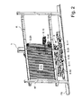
- the FIG. 1 shows a schematic diagram of an inventive clamping device S on a clamping frame R.
- the clamping device comprises a first support member S-10, which is movable over two guide elements S-11 and S-11 'along a guide rail FS.
- This first support element S-10 is designed here in the form of a support frame, in the area of which an adjustment mechanism S-30 for moving a tensioning unit S-40 is held.
- the adjustment mechanism S-30 may, as shown here, for example, comprise a spindle drive, via which the clamping unit S-40 in the surface of the support frame is movable back and forth.
- a spindle drive via which the clamping unit S-40 in the surface of the support frame is movable back and forth.
- another suitable drive is conceivable, such as a rack or belt drive or alternative drives, which are known to the person skilled in the art, depending on the power and cost.
- the clamping unit S-40 is firmly connected to a second support element S-20, which is also on a guide element S-21 movable on the guide rail FS.
- the support frame-shaped first support element S-10 is shown interrupted at the point at which it is crossed by the second rod-shaped support element S-20.
- the support frame should be closed in this embodiment. This can be the whole Move tensioning device S along the tensioning frame R in order to re-tension at this tensioned warp thread KF of a warp thread layer KFS.
- respective locking elements S-12 and S-22 are provided for individual locking of the first or second support element S-10 or S-20 on the guide rail FS.
- the locking element S-12 can optionally also be integrated into one of the guide elements S-11 or S-11 'of the first support element S-10 or arranged in front or behind it, as here with the locking element S-22 and the guide element S-21 of the second support member S-20 is the case.
- the locking elements S-12 and S-22 should be designed here as electromagnetically activated terminals.
- the clamping frame R itself can - but need not necessarily - be movably mounted relative to the clamping device S.
- it can guide elements R-10 and R-10 ', which allow its movement along the guide rail FS.
- the possibilities of movement of the clamping device S, the clamping unit S-40 and the clamping frame R are indicated by the individual double arrows.
- the adjusting mechanism S-30 then advances the support member S-20 along the warp thread layer KFS until the tension unit S-40 covers another portion of the warp thread layer KFS. This is followed by terminal S-22 and terminal S-12 opening, the tensioning unit S-40 being activated, and another portion of the warp thread layer KFS being re-tensioned, the support element S-10 being movable. Because during this time the support element S-10 is stationary relative to the clamping frame R, it can be moved counter to the clamping device S in order to ensure continuous processing of non-tensioned warp threads even in the step of "drawing" of the support element S-10. The reciprocal method of the support elements S-10 and S-20 can be continued until all warp threads KF of the warp thread layer KFS were re-tensioned or separated and retracted.
- the tensioning device S Due to the fact that the tensioning device S according to the invention can be moved on the guide rail FS, only low demands are placed on the ground conditions at the location where the device S is used. In particular, no rail system and no steel plates to support the individual components longer required.
- the tensioning device S also requires only a single drive system, to which moreover only small demands on the precision for the displacement of the components must be made. Overall, this means that apply comparatively low cost of the tensioning device and a puller based thereon are, and cost savings in the preparation of mounting the device on site are possible.
- a virtually interruption-free clamping or retraction process is possible by the advance of the support member S-10 can also be done during a separation of the warp threads.
- the inventive clamping device is very light and therefore extremely flexible. By the proposed clamping process, only small demands are placed on the power consumption of the clamping frame R, since only a part of the warp threads is always stretched.
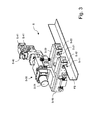
- FIG. 2 shows a concrete embodiment of the combination of retractor E and clamping frame R according FIG. 1 .
- the retraction device E is based on an inventive clamping device S, which also has a mobile chassis S-50, and further comprises a separating unit E-10 and a Einziehiata E-20 for warp threads in elements of a harness.
- a tensioning unit S-40 For positioning a tensioning unit S-40 on the warp thread layer KFS, a first and a second support element S-10 and S-20 are hung on a guide rail FS.
- the guide elements S-11 and S-11 ' give the retraction device E both stability and directional stability.
- the clamping frame R is arranged stationary, while the retractor E is displaceable thereto. In principle, however, the reverse arrangement is possible in which along a fixed Einziehaji E a clamping frame R is moved past.
- the width of the frame R corresponds to at least the widest Kettfaden für KFS to be processed.
- the frame R has means, the thread layer with the necessary for processing To provide tension.
- the frame R is rigidly connected at the bottom with the guide rail FS.
- the warp to be recovered is brought to the clamping frame R and the warp thread layer KFS clamped on this. When using a reed this is clamped in the designated holder.
- the retractor E is then positioned at the beginning of the warp yarn layer KFS and prepared for feeding by the required according to Einzugsrapport number of WebMften or Litzentragschienen and Lamellentragschienen is inserted into the designated holder, the magazines are filled for strand stack and fin stack, and the Input report is entered or programmed.
- the support members S-10 and S-20 have respective terminals S-12 and S-22 (shown in detail and designated in FIG. 3 ) on. While one clamp S-12 is fixedly connected to the retractor E, the clamp S-22 is slidable sideways with respect to the retractor E, here by means of an adjustment mechanism S-30 comprising a spindle drive S-31 (also shown and denoted in detail) in FIG. 3 ).
- the clamp S-22 now closes while the clamp S-12 is open.
- the tensioning unit S-40 is activated, so that warp threads KF are provided over a portion of the Kettfaden Mrs KFS with the necessary for error-free separation voltage.
- the drawing in of the warp threads KF begins by the separating unit E-10 detecting the respective nearest warp thread KF and the drawing unit E-20 pulling it into elements of a woven harness (not shown). During this process, the draw-in unit E-20 moves in each case so far in the direction of the thread layer KFS that the separating unit E-10 can grasp the warp thread KF to be separated next. This forward movement is triggered by the spindle drive S-31.
- clamp S-12 closes and the clamp S-22 opens.
- the spindle drive S-31 then moves the clamp S-22 so far in the direction of the warp thread layer KFS that a portion of the layer KFS can again be detected by the tensioning unit S-40.
- the terminal S-22 closes and the terminal S-12 opens, and the clamping unit S-40 is activated. This process is repeated until the last warp thread KF of the warp to be processed is retracted.
- the retractor E and the tensioning frame R move laterally from the beginning to the end of the warp thread layer KFS during drawing in accordance with the drawing-in progress.
- the elements of the woven harness are released from the pull-in device E and the tenter frame R, so that the pull-in device and the tenter frame R become independent of each other.
- the healds or heald bars with the strands and the slat support rails with lamellae including the warp are removed from the Einziehaji and Aufspann exotic. Clamping frame R and retractor E are thus free again for a next Einziehrata or its preparation and can also be spatially separated.
- the functional units of the retraction device E are not limited to a division into tensioning, separating and retraction units. It may also be a possible division into separating, cutting and Einziehü for feeding warp threads KF provided in the thread eyes of strands, warp stop guard slats and gaps in the reed. Further units can also be the inclusion of heald bars or healds, the storage, separation and distribution of healds on heald bars, the drawing of warp threads KF in a reed, the storage, separation and distribution of Kettfadenachterachterlamellen on disk carriers and the programming, operation and control of the system affect.
- FIG. 3 shows a clamping device S on the guide rail FS of the clamping frame R according FIG. 2 , Out
- the chassis S-50 is omitted, so that the support elements S-10 and S-20 can be clearly seen, which are interconnected via an adjustment mechanism S-30, which includes a spindle drive S-31.
- This adjustment mechanism S-30 a distance between the two support elements S-10 and S-20 is changeable.
- the support elements S-10 and S-20 have guide elements S-11 and S-21, which can be hung on the guide rail FS, so that the tensioning device S can be moved along the rail.
- the support elements S-10 and S-20 are equipped with respective terminals S-12 and S-22, which are for example electromechanically actuated, so that with mutual locking of the terminals S-12, S-22 and the corresponding actuation of the adjustment mechanism S- 30 a stepwise movement of the tensioning device S on the rail FS is possible.
- the spindle drive S-31 is held on the first support member S-10 and a tension unit S-40 on the second support member S-20.
- the clamping unit S-40 is initially movable over a path, which is predetermined by the adjusting mechanism S-30. To do this, terminal S-12 is closed and terminal S-22 is open.
- FIG. 4 shows a front view of the clamping device S on the guide rail FS according FIG. 3 ,
- the adjusting mechanism S-30 can be clearly seen, which can move the clamping unit S-40 in the direction indicated by the double arrow directions when the terminal S-12 is closed.
- the spindle drive S-31 is moved further when the adjustment mechanism S-30 is actuated with closed terminal S-22 and open terminal S-12.
- Continuous further processing can be carried out if, during the time in which the clamping unit S-40 is retightened, the clamping frame R is moved counter to the supporting element S-10, so that the separating unit E-10 can continuously separate warp threads KF.
- the two rod elements S-41 and S-41 'of the tensioning unit S-40 have tapered free ends, while the third rod element is formed roller-shaped to avoid damage to the threads KF.
- the particularly easy to see in the side view compact and lightweight construction of the clamping device S makes them particularly flexible and creates constructive leeway for further functional units for building a retraction device. Equipped with the tensioning device S according to the invention, the pulling-in device E permits a particularly reliable separation and thus the drawing in of warp threads KF.
- FIG. 5 finally shows a side view of a possible embodiment of the clamping device S on the guide rail FS according to FIG. 3 ,
- the third rod member S-42 is pivoted against a warp KF.
- an eccentric mechanism S-43 is provided, which takes on the one hand little space and on the other hand allows easy adjustment over a long way away.
- the locking element S-12 can be seen, which (as the underlying and thus not visible locking element S-22) provides a recess in the support element S-10 and S-20, by terminals S-12 and S-22 can be closed against the guide rail FS running therein.
- the inventive tensioning device S can thus be used both as an independent unit, but also provides a highly functional basis for building a retraction device with other functional components.
- Their simple construction makes them particularly reliable, flexible and cost-effective in terms of both their manufacture and maintenance.
Abstract
Description
Die Erfindung betrifft das Gebiet der Webereitechnik und insbesondere eine Spannvorrichtung zum Nachspannen von Kettfäden einer Kettfadenschicht nach Anspruch 1, eine Kombination aus dieser Spannvorrichtung und einem Spannrahmen nach Anspruch 9, eine Einziehvorrichtung nach Anspruch 12 umfassend die Spannvorrichtung, sowie ein Verfahren zum Nachspannen von Kettfäden einer Kettfadenschicht nach Anspruch 13.The invention relates to the field of weaving technique and in particular a tensioning device for tensioning warp threads of a warp thread layer according to claim 1, a combination of this tensioning device and a clamping frame according to claim 9, a retraction device according to
Bevor auf einer Webmaschine durch die Verbindung von Kettfäden und Schussfäden ein Gewebe oder Stoff entsteht, müssen die Kettfäden, einer bestimmten Ordnung folgend, in ein Webgeschirr eingezogen werden. Zu den Elementen des Webgeschirrs zählen normalerweise Webschäfte, Weblitzen, Kettfadenwächterlamellen sowie das Webblatt. Einziehen bedeutet, jeden einzelnen Kettfaden, der normalerweise auf einem Kettbaum in der benötigten Länge aufgewickelt ist, jeweils in das Fadenauge einer Kettfadenwächterlamelle, einer Weblitze sowie einer Lücke zwischen zwei Zähnen des Webblatts hindurchzuführen, so dass das Ende des eingezogenen Kettfadens anschliessend aus dem Webblatt herausragt. Das Gewebemuster wird dabei vorgegeben, indem die Weblitze einem bestimmten Webschaft zugeordnet ist bzw. in einen solchen eingeführt wird.Before a fabric or fabric is produced on a weaving machine by the combination of warp threads and weft threads, the warp threads, following a certain order, must be drawn into a weaving harness. The elements of the harness usually include healds, healds, Kettfadenwächterlamellen and the reed. Retraction means to pass each individual warp thread, which is normally wound on a warp beam in the required length, respectively into the thread eye of a warp stop guard, a heald and a gap between two teeth of the reed, so that the end of the drawn warp thread subsequently protrudes from the reed , The fabric pattern is given by the heald is assigned to a particular heald or is introduced into such.
Da Kettfäden normalerweise zu mehreren Hundert bis mehreren Tausend über eine bestimmte Breite parallel auf einem Kettbaum aufgewickelt sind, muss dieser Vorgang genauso oft wiederholt werden, bis eine Webkette vollständig in ein Webgeschirr eingezogen ist. Dies wurde und wird nach wie vor von Hand ausgeführt, es stehen aber auch Maschinen in verschiedenen Ausführungen zur Verfügung, die entweder einen Teil der Vorgänge (halbautomatische Einziehmaschinen) oder den ganzen Ablauf automatisch ausführen (automatische Einziehmaschinen).Since warp threads are usually wound up to several thousand over a certain width in parallel on a warp beam, this process must be repeated just as often until a warp is completely pulled into a harness. This has been and still is However, there are also machines available in various designs that either automatically carry out some of the operations (semi-automatic drawing-in machines) or the entire process (automatic drawing-in machines).
Halbautomatische Einziehmaschinen sind zwar relativ kostengünstig, haben gegenüber automatischen Einziehmaschinen aber den grossen Nachteil, dass eine Bedienperson zu 100% an der Maschine beschäftigt ist und den Einziehvorgang teilweise manuell ausführt. Auf diese Weise lässt sich gegenüber dem Einziehen von Hand nur eine geringe Produktivitätssteigerung erreichen, und die Fehlerrate ist relativ hoch.Although semi-automatic drawing-in machines are relatively inexpensive, compared to automatic drawing-in machines, they have the great disadvantage that an operator is 100% employed on the machine and carries out the pulling-in process partly manually. In this way, only a small increase in productivity can be achieved compared to manual feeding, and the error rate is relatively high.
Automatische Einziehmaschinen sind bekannt und auf dem Markt in verschiedenen Ausführungsformen erhältlich. Sie verfügen über eine selbsttätige Steuerung für alle Vorgänge, die für das Einziehen von Kettfäden in ein Webgeschirr notwendig sind. Die Aufgaben des Bedienpersonals beschränken sich auf die Vorbereitung und Überwachung des Ablaufs und der Funktionen sowie die Zu- und Wegfuhr des Ausgangsmaterials. Die Produktivität kann damit gegenüber dem Einziehen von Hand um ein Mehrfaches gesteigert und die Fehlerrate stark reduziert werden.Automatic drawing-in machines are known and available on the market in various embodiments. They have an automatic control system for all operations necessary for pulling warp threads into a harness. The tasks of the operating personnel are limited to the preparation and monitoring of the sequence and the functions as well as the supply and removal of the starting material. As a result, productivity can be increased many times over manual feeding and the error rate can be greatly reduced.
Automatische Einziehmaschinen bestehen grundsätzlich aus zwei gegeneinander verschiebbaren Haupteinheiten. Die eine Einheit enthält die Vorrichtung zur Vorbereitung der Webkette (Aufspanneinheit für die Kettfadenschicht) , die andere Einheit umfasst die Vorrichtung zum Einziehen und zur Aufnahme des Webgeschirrs (Einzieheinheit). Einzieheinheit und Aufspanneinheit bewegen sich während des Einziehens relativ zueinander seitwärts vom Anfang zum Ende der Kettfadenschicht entsprechend des Einzugsfortschritts.Automatic feeding machines basically consist of two main units that can be moved against each other. The one unit contains the warp preparation apparatus (warp thread layer mounting unit), and the other unit includes the apparatus for drawing and receiving the weaving unit (draw-in unit). Retractable unit and clamping unit move during feeding relative to each other sideways from the beginning to the end of the warp thread according to the Einzugsestschritts.
Die zuvor beschriebene Ausführungsform automatischer Einziehmaschinen beinhaltet stets eine Aufspannvorrichtung (Faden- oder auch Spannrahmen), auf welche die zu verarbeitende Kettfadenschicht aufzubringen ist. Ab dieser Kettfadenschicht werden die Kettfäden einzelnen in sequentieller Reihenfolge abgeholt (separiert) und von der Einzieheinheit in die Webgeschirrelemente eingezogen. Ein fehlerfreies Separieren der einzelnen Kettfäden bedingt, dass die Kettfäden mit einer bestimmten Vorspannung auf dem Fadenrahmen aufgespannt sind. Diese Spannung variiert je nach Material und Garnbeschaffenheit. Auf eine ganze Webkettenbreite summieren sich erhebliche Kräfte, die sich im Verlauf des Einziehprozesses verändern. Dies erfordert unter Umständen Eingriffe durch das Bedienpersonal, indem die Vorspannung nachjustiert wird. Um diese Probleme zu umgehen, existieren Lösungen gemäss
Ein weiteres Problemfeld bildet die Tatsache, dass es sich bei den zwei gegeneinander verschiebbaren Haupteinheiten um schwere und entsprechend träge Körper handelt, deren Gewicht zudem abhängig von der jeweiligen Anwendung ist. Da sich aber die Einziehposition zur Position des zu separierenden Kettfadens im Verlaufe des Einziehprozesses fortlaufend ändert, ist eine periodische Verschiebung mindestens einer der beiden Haupteinheiten zwingend. Zur Entschärfung dieses Problems wurde beispielsweise eine Lösung gemäss
Andere Lösungen zur relativen Verschiebung von Einzieheinheit gegenüber Aufspanneinheit sind beispielsweise in
Es ist Aufgabe der vorliegenden Erfindung, die genannten Nachteile zu überwinden und ein verbessertes Nachspannen von Kettfäden einer Kettfadenschicht zu ermöglichen, das mechanisch einfach zu bewerkstelligen, zuverlässig und genau, flexibel anwendbar und kostengünstig zu betreiben ist.It is an object of the present invention to overcome the disadvantages mentioned and to allow an improved re-tensioning of warp threads of a warp thread layer, which is mechanically simple to accomplish, reliable and accurate, flexibly applicable and inexpensive to operate.
Diese Aufgabe wird durch die Spannvorrichtung nach Anspruch 1 gelöst.This object is achieved by the clamping device according to claim 1.
Ein wesentlicher Punkt der erfindungsgemässen Spannvorrichtung besteht zunächst darin, dass sich diese selbsttätig allein unter koordinierter Betätigung des Verstellmechanismus und der Arretierungselemente entlang der Führungsschiene bewegen kann. Der Verstellmechanismus muss dazu lediglich einen einzigen Antrieb umfassen, was zu einer erheblichen Gewichtsreduktion beiträgt. Sowohl die autonome Beweglichkeit als auch das reduzierte Gewicht tragen dazu bei, dass die Vorrichtung besonders flexibel einsetzbar ist. Da die Zuverlässigkeit und Genauigkeit der Vorrichtung auch von der Führungsschiene bestimmt wird, sind nur noch geringe Anforderungen an die Bodenbeschaffenheit des Einsatzortes zu stellen. Insbesondere werden die Kosten dadurch gesenkt, dass kein Schienensystem oder keine Stahlplatten mehr erforderlich sind.An essential point of the clamping device according to the invention consists first of all in that it can automatically move along the guide rail alone under coordinated actuation of the adjusting mechanism and of the locking elements. The adjustment mechanism has to include only a single drive, which contributes to a significant weight reduction. Both the autonomous mobility and the reduced weight contribute to the device being particularly flexible. Since the reliability and accuracy of the device is also determined by the guide rail, only low demands are placed on the soil condition of the site. In particular, the cost is reduced by no longer requiring a rail system or steel plates.
Vorteilhafte Ausführungsformen der erfindungsgemässen Spannvorrichtung sind in den Unteransprüchen 2 bis 8 angegeben.Advantageous embodiments of the inventive clamping device are specified in the dependent claims 2 to 8.
In einer bevorzugten Ausführungsform weist die Spanneinheit drei ungefähr parallel zueinander ausgerichtete Stabelemente auf, von denen ein erstes und ein zweites Stabelement jeweilige Anschläge für wenigstens einen Kettfaden bilden, und ein drittes Stabelement zum Ergreifen und Nachspannen des Kettfadens zwischen dem ersten und zweiten Stabelement hindurch bewegbar ist. Mit einer solchen Spanneinheit lässt sich prinzipiell jede gewünschte Nachspannung erzeugen. Zum Verfahren der Spanneinheit wird das dritte Stabelement wieder in seine von den beiden anderen Stabelementen entfernte Position zurückbewegt, um einen weiteren Teil der Kettfadenschicht in dem dazwischen liegenden Raum aufzunehmen. Um diesen weiteren Teil in diesen Raum zu geleiten und eventuelle Blockaden zwischen Spanneinheit und Kettfadenschicht zu vermeiden, läuft dabei ein jeweils freies Ende von wenigstens einem der Stabelemente bevorzugt spitz zu. Das dritte Stabelement ist dabei bevorzugt über einen Exzentermechanismus bewegbar, um einen möglichst einfachen und gleichzeitig platzsparenden Antrieb über einen weiten Verstellweg hinweg zu gewährleisten.In a preferred embodiment, the tensioning unit comprises three bar elements approximately aligned parallel to each other, of which a first and a second bar element form respective stops for at least one warp thread, and a third bar element for gripping and tensioning the warp thread is movable between the first and second bar elements , With such a clamping unit can be generated in principle any desired post-tension. To move the clamping unit, the third bar member is moved back to its position remote from the other two bar members to receive another portion of the warp thread layer in the space therebetween. To this other part in this room too To guide and avoid any blockages between the clamping unit and warp layer, while a respective free end of at least one of the rod elements preferably runs pointed. The third rod element is preferably movable via an eccentric mechanism in order to ensure the simplest and at the same time space-saving drive over a wide adjustment path.
In einer weiteren bevorzugten Ausführungsform weisen die Arretierelemente einen Klemm- oder Rastmechanismus auf, der eine besonders einfache, schnelle und sichere Feststellung der Stützelemente an einer Führungsschiene erlaubt. Ein solcher Mechanismus kann z.B. über elektromotorisch oder elektromagnetisch betätigbare Stellglieder realisiert werden. Der Verstellmechanismus für den Abstand zwischen den Stützelementen umfasst dagegen bevorzugt einen Spindelantrieb, welcher besonders einfach und platzsparend realisierbar ist und zudem eine ausreichend genaue Positionierung der Spanneinheit zulässt.In a further preferred embodiment, the locking elements on a clamping or locking mechanism, which allows a particularly simple, fast and secure determination of the support elements on a guide rail. Such a mechanism may e.g. be realized by electric motor or electromagnetically actuated actuators. The adjustment mechanism for the distance between the support elements, however, preferably includes a spindle drive, which is particularly simple and space-saving feasible and also allows a sufficiently accurate positioning of the clamping unit.
Ein besonders flexibler Einsatz der Spannvorrichtung ist dann gewährleistet, wenn deren Stützelemente an einem mobilen Chassis gelagert sind. Eine derart ausgestattete Vorrichtung kann insbesondere an mehreren Spannrahmen betrieben werden, so dass nicht für jeden Spannrahmen eine lokal installierte Spannvorrichtung vorhanden sein muss. Bevorzugt wird dabei eines der beiden Stützelemente fest mit dem mobilen Chassis verbunden, damit sich dieses mit dem Stützelement mitbewegt, und ein entsprechend kurzes Chassis zur Halterung der Stützelemente ausreicht.A particularly flexible use of the tensioning device is ensured when the support elements are mounted on a mobile chassis. Such a device can in particular be operated on a plurality of clamping frames, so that a locally installed clamping device does not have to be present for each clamping frame. Preferably, one of the two support elements is fixedly connected to the mobile chassis, so that this moves with the support element, and a correspondingly short chassis sufficient to support the support elements.
Die vorstehende Aufgabe wird auch durch eine Kombination aus der vorstehenden Spannvorrichtung und einem Spannrahmen nach Anspruch 9 gelöst.The above object is also achieved by a combination of the above clamping device and a clamping frame according to claim 9.
Ein wesentlicher Punkt der erfindungsgemässen Kombination besteht dabei darin, dass die Führungsschiene immer exakt so zum Spannrahmen ausgerichtet ist, wie dies zum Nachspannen der Kettfäden erforderlich ist.An essential point of the inventive combination consists in the fact that the guide rail is always aligned exactly to the clamping frame, as is required for tensioning the warp threads.
Bevorzugte Ausführungsformen der erfindungsgemässen Kombination sind in den Unteransprüchen 10 und 11 angegeben.Preferred embodiments of the inventive combination are given in the
Danach ist es bevorzugt, wenn die Führungsschiene als ein Teil des Spannrahmens ausgebildet ist, da nur ein Teil der Kettfäden gespannt wird, und nur noch geringe Anforderungen an die Kraftaufnahme des Spannrahmens gestellt werden müssen. Da der Spannrahmen insgesamt leichter wird, kann dieser auch gegenüber der Spannvorrichtung beweglich gelagert sein. Dadurch kann dieser gegenüber der Spanneinheit bewegt werden, wenn diese selbst arretiert ist, was eine insgesamt kontinuierliche Bewegung der Spanneinheit entlang des Rahmens ermöglicht, welche die Bearbeitungszeit einer Kettfadenschicht verkürzt.Thereafter, it is preferred that the guide rail is formed as a part of the clamping frame, since only a portion of the warp threads is stretched, and only small demands on the power consumption of the clamping frame must be made. Since the clamping frame is lighter overall, it can also be mounted movably relative to the clamping device. This allows it to be moved with respect to the clamping unit when it is self-locked, which allows for an overall continuous movement of the clamping unit along the frame, which shortens the processing time of a warp thread layer.
Die vorstehende Aufgabe wird auch durch eine Einziehvorrichtung zum Einziehen von Kettfäden einer Kettfadenschicht nach Anspruch 12 gelöst, welche die vorstehende Spannvorrichtung umfasst.The above object is also achieved by a warp thread retraction threading apparatus as claimed in
Ein wesentlicher Punkt der erfindungsgemässen Einziehvorrichtung besteht dabei darin, dass diese alle Vorteile der erfindungsgemässen Spanneinheit gleichzeitig für das Separieren und Einziehen der Kettfäden nutzt. So kann die Einziehvorrichtung insbesondere auch auf dem fahrbaren Chassis der Spannvorrichtung aufbauen, an deren Spanneinheit im einfachsten Fall noch die Separier- und Einzieheinheit gehalten sind und mit dieser mitbewegt werden.An essential point of the inventive retraction device is that it uses all the advantages of the clamping unit according to the invention at the same time for separating and drawing in the warp threads. So the retractor can in particular also build on the movable chassis of the clamping device, at the clamping unit in the simplest case nor the separating and Einzieheinheit are held and moved with this.
Eine vorteilhafte Weiterbildung der erfindungsgemässen Einziehvorrichtung ist im Unteranspruch 13 angegeben.An advantageous development of the inventive retraction device is specified in the dependent claim 13.
Bevorzugt sind dabei die Separiereinheit und/oder die Einzieheinheit an dem Stützelement gelagert, das die Spanneinheit nicht trägt. Dadurch kann insbesondere eine kontinuierliche Weiterverarbeitung der Kettfäden gewährleistet werden, wenn die Spanneinheit nicht bewegt wird. Dies ist dann der Fall, wenn deren Stützelement arretiert und das andere Stützelement - mit der daran gelagerten Separiereinheit und Einzieheinheit - nachgezogen wird, um wieder Spielraum zur Bewegung der Spanneinheit zu schaffen.The separating unit and / or the draw-in unit are preferably mounted on the support element which does not carry the tensioning unit. As a result, in particular a continuous further processing of the warp threads can be ensured if the clamping unit is not moved. This is the case when the support member is locked and the other support element - with the separator mounted thereon and Einzieheinheit - is tightened to again to create latitude for moving the clamping unit.
Die vorstehende Aufgabe wird zudem durch ein Verfahren zum Nachspannen von Kettfäden einer Kettfadenschicht nach Anspruch 14 gelöst, das die vorstehende Spannvorrichtung nutzt.The above object is also achieved by a method for tensioning warp yarns of a warp thread layer according to claim 14, which utilizes the above tensioning device.
Ein wesentlicher Punkt des erfindungsgemässen Verfahrens besteht dabei darin, dass durch wechselseitiges Arretieren der Stützelemente und nachfolgender Betätigung des Verstellmechanismus der Spanneinheit deren besonders einfache Bewegung entlang der Kettfadenschicht möglich ist, die keine aufwändigen Antriebe und komplexen Kinematiken mehr benötigt. Dies erhöht insbesondere die Zuverlässigkeit und Genauigkeit des Verfahrens.An essential point of the inventive method consists in that by mutual locking of the support elements and subsequent operation of the adjustment of the clamping unit whose particularly simple movement along the warp thread layer is possible, which no longer requires complex drives and complex kinematics. This particularly increases the reliability and accuracy of the method.
Vorteilhafte Weiterbildungen des erfindungsgemässen Verfahrens sind in den Unteransprüchen 15 und 16 angegeben.Advantageous developments of the inventive method are given in the subclaims 15 and 16.
In einer bevorzugten Weiterbildung des Verfahren wird die Kettfadenschicht gegenüber der Spanneinheit bewegt, wenn deren Stützelement festgestellt ist, so dass sich eine insgesamt kontinuierliche Bewegung der Spanneinheit entlang der Kettfadenschicht ergibt. Damit wird auch bei arretierter Spanneinheit ein Nachspannen weiterer Kettfäden möglich, so dass sich eine insgesamt verkürzte Bearbeitungszeit der Kettfadenschicht ergibt.In a preferred development of the method, the warp thread layer is moved relative to the tensioning unit when its support element is fixed, so that a total continuous movement of the tensioning unit results along the warp thread layer. Thus, a retightening of further warp threads is possible even with locked clamping unit, so that there is an overall shortened processing time of the warp thread layer.
In einer weiteren bevorzugten Weiterbildung des Verfahrens wird zudem eine Separiereinheit und eine Einzieheinheit einer Bewegung der Spanneinheit nachfolgend entlang der Kettfadenschicht bewegt, und ein jeweils separierter Kettfaden in Elemente eines Webgeschirrs eingezogen. Die Vorteile des erfindungsgemässen Nachspannvorgangs werden somit auch für das Separieren und Einziehen von Kettfäden im gleichen Verfahren nutzbar.In a further preferred development of the method, furthermore, a separating unit and a draw-in unit of a movement of the clamping unit are subsequently moved along the warp thread layer, and a respectively separated warp thread is drawn into elements of a woven harness. The advantages of the inventive Nachspannvorgangs thus be used for the separation and drawing of warp threads in the same process.
Die Erfindung wird nachfolgend anhand einer Prinzipskizze und eines konkreten Ausführungsbeispiels unter Bezugnahme auf die beiliegenden Figuren im Detail erläutert. Gleiche oder funktionsgleiche Bauteile sind mit den gleichen Bezugsziffern versehen. Es zeigen:
- Figur 1
- eine Prinzipdarstellung einer erfindungsgemässen Spanneinheit an einem Spannrahmen;
- Figur 2
- eine konkrete Ausführungsform der Kombination aus Einzieheinheit und Spannrahmen gemäss
Figur 1 ; - Figur 3
- eine Spannvorrichtung an der Führungsschiene des Spannrahmens gemäss
Figur 2 ; - Figur 4
- eine Vorderansicht der Spannvorrichtung an der Führungsschiene gemäss
Figur 3 , und - Figur 5
- eine Seitenansicht der Spannvorrichtung an der Führungsschiene gemäss
Figur 3 .
- FIG. 1
- a schematic diagram of an inventive clamping unit on a clamping frame;
- FIG. 2
- a concrete embodiment of the combination of Einzieheinheit and tenter according to
FIG. 1 ; - FIG. 3
- a clamping device on the guide rail of the clamping frame according to
FIG. 2 ; - FIG. 4
- a front view of the clamping device on the guide rail according
FIG. 3 , and - FIG. 5
- a side view of the clamping device on the guide rail according
FIG. 3 ,
Die
Auch der Spannrahmen R selbst kann - muss aber nicht notwendigerweise - gegenüber der Spannvorrichtung S beweglich gelagert sein. Dazu kann er Führungselemente R-10 und R-10' aufweisen, die seine Bewegung entlang der Führungsschiene FS ermöglichen. Die Bewegungsmöglichkeiten der Spannvorrichtung S, der Spanneinheit S-40 und des Spannrahmens R sind durch die einzelnen Doppelpfeile angedeutet.Also, the clamping frame R itself can - but need not necessarily - be movably mounted relative to the clamping device S. For this purpose, it can guide elements R-10 and R-10 ', which allow its movement along the guide rail FS. The possibilities of movement of the clamping device S, the clamping unit S-40 and the clamping frame R are indicated by the individual double arrows.
Ist die zu spannende Kettfadenschicht auf dem Rahmen R aufgespannt und die Spannvorrichtung S mit der Führungsschiene FS verbunden, kann der Spannablauf beginnen. Dabei schliesst zunächst die Klemme S-22 und die Klemme S-12 ist offen. Die Spanneinheit S-40 wird aktiviert und ein Teilbereich der Kettfadenschicht KFS wird nachgespannt. Die nachgespannten Kettfäden KF könnten dann z.B. durch entsprechende Verarbeitungseinheiten separiert und in Elemente eines Webgeschirrs eingezogen werden. Zum Verarbeiten weiterer Kettfäden wird das Stützelement S-10 mittels Verstellmechanismus S-30 solange entlang der Kettfadenschicht KFS bewegt, bis der nachgespannte Teilbereich der Kettfadenschicht KFS verarbeitet wurde. Dann öffnet die Klemme S-22, und die Klemme S-12 schliesst. Der Verstellmechanismus S-30 bewegt daraufhin das Stützelement S-20 entlang der Kettfadenschicht KFS weiter, bis die Spanneinheit S-40 einen weiteren Teilbereich der Kettfadenschicht KFS abdeckt. Hierauf schliesst Klemme S-22 und Klemme S-12 öffnet, die Spanneinheit S-40 wird aktiviert, und ein weiterer Teilbereich der Kettfadenschicht KFS wird nachgespannt, das Stützelement S-10 wird bewegbar. Weil in dieser Zeit das Stützelement S-10 gegenüber dem Spannrahmen R still steht, kann dieser der Spannvorrichtung S entgegen bewegt werden, um auch im Schritt des "Nachziehens" des Stützelements S-10 ein kontinuierliches Verarbeiten nicht nachgespannter Kettfäden zu gewährleisten. Das wechselseitige Verfahren der Stützelemente S-10 und S-20 kann solange fortgesetzt werden, bis alle Kettfäden KF der Kettfadenschicht KFS nachgespannt bzw. separiert und eingezogen wurden.If the warp thread layer to be tensioned is clamped on the frame R and the tensioning device S is connected to the guide rail FS, the tensioning process can begin. At first the terminal S-22 closes and the terminal S-12 is open. The clamping unit S-40 is activated and a portion of the warp thread layer KFS is re-tensioned. The tensioned warp threads KF could then be separated, for example by appropriate processing units and fed into elements of a harness. For processing further warp threads, the support element S-10 by means of adjusting mechanism S-30 as long along the warp thread layer KFS moves until the re-tensioned portion of the warp thread layer KFS has been processed. Then terminal S-22 opens and terminal S-12 closes. The adjusting mechanism S-30 then advances the support member S-20 along the warp thread layer KFS until the tension unit S-40 covers another portion of the warp thread layer KFS. This is followed by terminal S-22 and terminal S-12 opening, the tensioning unit S-40 being activated, and another portion of the warp thread layer KFS being re-tensioned, the support element S-10 being movable. Because during this time the support element S-10 is stationary relative to the clamping frame R, it can be moved counter to the clamping device S in order to ensure continuous processing of non-tensioned warp threads even in the step of "drawing" of the support element S-10. The reciprocal method of the support elements S-10 and S-20 can be continued until all warp threads KF of the warp thread layer KFS were re-tensioned or separated and retracted.
Dadurch, dass die erfindungsgemässe Spannvorrichtung S an der Führungsschiene FS verfahrbar ist, bestehen lediglich geringe Anforderungen an die Bodenbeschaffenheit an dem Ort, wo die Vorrichtung S zum Einsatz kommt. Insbesondere ist keine Schienensystem und sind keine Stahlplatten zur Stützung der einzelnen Komponenten mehr erforderlich. Die Spannvorrichtung S benötigt zudem lediglich ein einziges Antriebssystem, an das darüber hinaus nur geringe Anforderungen an die Präzision für die Verschiebung der Komponenten gestellt werden müssen. Insgesamt bedeutet dies, dass vergleichsweise geringe Kosten für die Spannvorrichtung und eine darauf aufbauende Einziehvorrichtung aufzubringen sind, und Kosteneinsparungen bei der Vorbereitung der Montage der Vorrichtung vor Ort möglich sind. Hinzu kommt, dass ein praktisch unterbruchsfreier Spann- bzw. Einziehprozess möglich ist, indem der Vorschub des Stützelements S-10 auch während eines Separierens der Kettfäden erfolgen kann. Gleichzeitig ist die erfindungsgemässe Spannvorrichtung sehr leicht und damit äusserst flexibel einsetzbar. Durch den vorgestellten Spannprozess sind zudem nur geringe Anforderungen an die Kraftaufnahme des Spannrahmens R zu stellen, da nur immer ein Teil der Kettfäden gespannt wird.Due to the fact that the tensioning device S according to the invention can be moved on the guide rail FS, only low demands are placed on the ground conditions at the location where the device S is used. In particular, no rail system and no steel plates to support the individual components longer required. The tensioning device S also requires only a single drive system, to which moreover only small demands on the precision for the displacement of the components must be made. Overall, this means that apply comparatively low cost of the tensioning device and a puller based thereon are, and cost savings in the preparation of mounting the device on site are possible. In addition, a virtually interruption-free clamping or retraction process is possible by the advance of the support member S-10 can also be done during a separation of the warp threads. At the same time, the inventive clamping device is very light and therefore extremely flexible. By the proposed clamping process, only small demands are placed on the power consumption of the clamping frame R, since only a part of the warp threads is always stretched.
Die
Der Spannrahmen R ist dabei ortsfest angeordnet, während die Einziehvorrichtung E dazu verschiebbar ist. Grundsätzlich ist jedoch auch die umgekehrte Anordnung möglich, bei der entlang einer ortsfesten Einzieheinheit E ein Spannrahmen R vorbei bewegt wird. Die Breite des Rahmens R entspricht dabei mindestens der breitesten zu verarbeitenden Kettfadenschicht KFS. Der Rahmen R verfügt über Mittel, die Fadenschicht mit der für die Verarbeitung notwendigen Spannung zu versehen. Der Rahmen R ist am Boden mit der Führungsschiene FS starr verbunden.The clamping frame R is arranged stationary, while the retractor E is displaceable thereto. In principle, however, the reverse arrangement is possible in which along a fixed Einzieheinheit E a clamping frame R is moved past. The width of the frame R corresponds to at least the widest Kettfadenschicht KFS to be processed. The frame R has means, the thread layer with the necessary for processing To provide tension. The frame R is rigidly connected at the bottom with the guide rail FS.
Zu Beginn des Einzugsprozesses wird die einzuziehende Webkette zum Spannrahmen R gebracht und die Kettfadenschicht KFS auf diesem aufgespannt. Bei Verwendung eines Webblatts wird dieses in die dafür vorgesehene Halterung eingespannt. Die Einziehvorrichtung E wird dann an den Anfang der Kettfadenschicht KFS positioniert und für das Einziehen vorbereitet, indem die gemäss Einzugsrapport benötigte Anzahl von Webschäften bzw. Litzentragschienen und Lamellentragschienen in die dafür vorgesehene Halterung eingelegt wird, die Magazine für Litzenstapel und Lamellenstapel aufgefüllt werden, und der Einzugsrapport eingegeben bzw. einprogrammiert wird. Mit Auslösung des Starts beginnt dann der Einziehprozess, wobei das Einziehen der Kettfäden auf bekannte Weise in Litzen, Lamellen und das Webblatt bis zum letzten gemäss Einzugsrapport programmierten Kettfaden KF erfolgt. Die Litzen und Lamellen mit darin eingezogenen Kettfäden werden auf die dafür gemäss Einzugsrapport vorgesehen Tragschienen verteilt. Die zuletzt in die Blattlücken des Webblatts eingezogenen Kettfäden KF ragen vorne aus dem Webblatt heraus.At the beginning of the collection process, the warp to be recovered is brought to the clamping frame R and the warp thread layer KFS clamped on this. When using a reed this is clamped in the designated holder. The retractor E is then positioned at the beginning of the warp yarn layer KFS and prepared for feeding by the required according to Einzugsrapport number of Webschäften or Litzentragschienen and Lamellentragschienen is inserted into the designated holder, the magazines are filled for strand stack and fin stack, and the Input report is entered or programmed. With triggering of the start then the Einziehprozess, wherein the retraction of the warp threads takes place in known manner in strands, fins and the reed to the last according to Einzugsrapport programmed warp KF. The strands and lamellae with warp threads drawn in are distributed on the support rails provided for this according to the pull-in repeat. The last in the leaf gaps of the reed entangled warp KF project forward from the reed out.
Zur Fortbewegung der Einziehvorrichtung E entlang der Führungsschiene FS weisen die Stützelemente S-10 und S-20 jeweilige Klemmen S-12 und S-22 (detailliert gezeigt und bezeichnet in
In einer Ausgangslage, wenn die Einziehvorrichtung E an dem Rahmen R positioniert und die Separiereinheit E-10 zum Erfassen eines Kettfadens bereit ist, schliesst nun die Klemme S-22, während die Klemme S-12 offen ist. Die Spanneinheit S-40 wird aktiviert, so dass Kettfäden KF über einen Teilbereich der Kettfadenschicht KFS mit der für ein fehlerfreies Separieren notwendigen Spannung versehen werden. Das Einziehen der Kettfäden KF beginnt, indem die Separiereinheit E-10 den jeweils nächstliegenden Kettfaden KF erfasst und die Einzieheinheit E-20 diesen in Elemente eines Webgeschirrs (nicht dargestellt) einzieht. Die Einzieheinheit E-20 bewegt sich während dieses Prozesses jeweils soweit in Richtung der Fadenschicht KFS, dass die Separiereinheit E-10 den nächstfolgend zu separierenden Kettfaden KF erfassen kann. Diese Vorwärtsbewegung wird durch den Spindelantrieb S-31 ausgelöst.In a starting position, when the retractor E is positioned on the frame R and the separating unit E-10 is ready to engage a warp, the clamp S-22 now closes while the clamp S-12 is open. The tensioning unit S-40 is activated, so that warp threads KF are provided over a portion of the Kettfadenschicht KFS with the necessary for error-free separation voltage. The drawing in of the warp threads KF begins by the separating unit E-10 detecting the respective nearest warp thread KF and the drawing unit E-20 pulling it into elements of a woven harness (not shown). During this process, the draw-in unit E-20 moves in each case so far in the direction of the thread layer KFS that the separating unit E-10 can grasp the warp thread KF to be separated next. This forward movement is triggered by the spindle drive S-31.
Sind alle Kettfäden im Teilbereich der Kettfadenschicht, welcher durch die Spanneinheit S-40 gespannt ist, eingezogen, schliesst Klemme S-12 und die Klemme S-22 öffnet. Der Spindelantrieb S-31 bewegt darauf die Klemme S-22 soweit in Richtung der Kettfadenschicht KFS, dass erneut ein Teilbereich der Schicht KFS durch die Spanneinheit S-40 erfasst werden kann. Dann schliesst die Klemme S-22 und die Klemme S-12 öffnet, und die Spanneinheit S-40 wird aktiviert. Dieser Vorgang wird so oft wiederholt, bis der letzte Kettfaden KF der abzuarbeitenden Webkette eingezogen ist.If all the warp threads in the section of the warp thread layer which is stretched by the tensioning unit S-40 are pulled in, clamp S-12 closes and the clamp S-22 opens. The spindle drive S-31 then moves the clamp S-22 so far in the direction of the warp thread layer KFS that a portion of the layer KFS can again be detected by the tensioning unit S-40. Then the terminal S-22 closes and the terminal S-12 opens, and the clamping unit S-40 is activated. This process is repeated until the last warp thread KF of the warp to be processed is retracted.
In der Summe bewegen sich damit die Einziehvorrichtung E und der Spannrahmen R während des Einziehens relativ zueinander seitwärts vom Anfang zum Ende der Kettfadenschicht KFS entsprechend dem Einzugsfortschritt. Ist das Ende der Kettfadenschicht KFS erreicht und der letzte Kettfaden KF eingezogen, werden die Elemente des Webgeschirrs von der Einziehvorrichtung E und dem Spannrahmen R gelöst, so dass die Einziehvorrichtung und der Spannrahmen R voneinander unabhängig werden. Zum Abrüsten werden das Webblatt, die Webschäfte bzw. Litzentragschienen mit den Litzen sowie die Lamellentragschienen mit Lamellen samt der Webkette von der Einzieheinheit und der Aufspanneinheit entfernt. Spannrahmen R und Einziehvorrichtung E sind damit wieder frei für einen nächsten Einziehprozess bzw. dessen Vorbereitung und können auch räumlich voneinander entfernt werden.In sum, therefore, the retractor E and the tensioning frame R move laterally from the beginning to the end of the warp thread layer KFS during drawing in accordance with the drawing-in progress. When the end of the warp yarn layer KFS is reached and the last warp yarn KF is pulled in, the elements of the woven harness are released from the pull-in device E and the tenter frame R, so that the pull-in device and the tenter frame R become independent of each other. To remove the reed, the healds or heald bars with the strands and the slat support rails with lamellae including the warp are removed from the Einzieheinheit and Aufspanneinheit. Clamping frame R and retractor E are thus free again for a next Einziehprozess or its preparation and can also be spatially separated.
Grundsätzlich sind die Funktionseinheiten der Einziehvorrichtung E dabei nicht auf eine Aufteilung in Spann-, Separier- und Einzieheinheit eingeschränkt. Es kann auch eine mögliche Aufteilung in Separier-, Schneid- und Einzieheinheit zum Einziehen von Kettfäden KF in die Fadenaugen von Litzen, Kettfadenwächterlamellen und Lücken im Webblatt vorgesehen sein. Weitere Einheiten können zudem die Aufnahme von Litzentragschienen oder Webschäften, die Magazinierung, Separierung und Verteilung von Weblitzen auf Litzentragschienen, das Einziehen von Kettfäden KF in ein Webblatt, die Magazinierung, Separierung und Verteilung von Kettfadenwächterlamellen auf Lamellentragschienen und die Programmierung, Bedienung und Steuerung der Anlage betreffen.In principle, the functional units of the retraction device E are not limited to a division into tensioning, separating and retraction units. It may also be a possible division into separating, cutting and Einzieheinheit for feeding warp threads KF provided in the thread eyes of strands, warp stop guard slats and gaps in the reed. Further units can also be the inclusion of heald bars or healds, the storage, separation and distribution of healds on heald bars, the drawing of warp threads KF in a reed, the storage, separation and distribution of Kettfadenachterachterlamellen on disk carriers and the programming, operation and control of the system affect.
Die
Die
Die
Die erfindungsgemässe Spannvorrichtung S ist damit sowohl als eigenständige Einheit einsetzbar, bietet aber zudem eine hochfunktionale Basis zum Aufbau einer Einziehvorrichtung mit weiteren Funktionskomponenten. Ihr einfacher Aufbau macht sie besonders zuverlässig, flexibel einsetzbar und kostengünstig, was sowohl ihre Herstellung wie auch Wartung anbetrifft. Diese Vorteile wohnen auch einer Einziehmaschine inne, die eine solche Spannvorrichtung umfasst, und lässt die Einziehqualität und -geschwindigkeit deutlich steigen.The inventive tensioning device S can thus be used both as an independent unit, but also provides a highly functional basis for building a retraction device with other functional components. Their simple construction makes them particularly reliable, flexible and cost-effective in terms of both their manufacture and maintenance. These advantages are also inherent in a drawing machine incorporating such a jig and significantly increase the threading quality and speed.
Claims (16)
Priority Applications (6)
| Application Number | Priority Date | Filing Date | Title |
|---|---|---|---|
| EP10405105A EP2388362B1 (en) | 2010-05-21 | 2010-05-21 | Tensioning device and method for retensioning warp filaments of a warp filament layer |
| KR1020110047204A KR20110128243A (en) | 2010-05-21 | 2011-05-19 | A tensioning device and a method for the retensioning of warp threads of a warp thread layer |
| JP2011113986A JP5719688B2 (en) | 2010-05-21 | 2011-05-20 | Tension applying device and method for re-applying tension to warp of warp layer |
| TW100117751A TWI535906B (en) | 2010-05-21 | 2011-05-20 | A tensioning device and a method for the retensioning of warp threads of a warp thread layer |
| PCT/CH2011/000118 WO2011143787A1 (en) | 2010-05-21 | 2011-05-20 | Tensioning device and method for re-tensioning warp threads of a warp thread layer |
| CN201180002902.3A CN102575390B (en) | 2010-05-21 | 2011-05-20 | Tensioning device and method for re-tensioning warp threads of a warp thread layer |
Applications Claiming Priority (1)
| Application Number | Priority Date | Filing Date | Title |
|---|---|---|---|
| EP10405105A EP2388362B1 (en) | 2010-05-21 | 2010-05-21 | Tensioning device and method for retensioning warp filaments of a warp filament layer |
Publications (2)
| Publication Number | Publication Date |
|---|---|
| EP2388362A1 true EP2388362A1 (en) | 2011-11-23 |
| EP2388362B1 EP2388362B1 (en) | 2012-12-26 |
Family
ID=42732272
Family Applications (1)
| Application Number | Title | Priority Date | Filing Date |
|---|---|---|---|
| EP10405105A Active EP2388362B1 (en) | 2010-05-21 | 2010-05-21 | Tensioning device and method for retensioning warp filaments of a warp filament layer |
Country Status (6)
| Country | Link |
|---|---|
| EP (1) | EP2388362B1 (en) |
| JP (1) | JP5719688B2 (en) |
| KR (1) | KR20110128243A (en) |
| CN (1) | CN102575390B (en) |
| TW (1) | TWI535906B (en) |
| WO (1) | WO2011143787A1 (en) |
Families Citing this family (3)
| Publication number | Priority date | Publication date | Assignee | Title |
|---|---|---|---|---|
| CN106987988B (en) * | 2017-05-10 | 2018-07-20 | 深圳市海弘装备技术有限公司 | A kind of automatic warp-pulling equipment moving operation on the ground |
| CN109778397B (en) * | 2019-02-27 | 2020-05-19 | 深圳市海弘装备技术有限公司 | Yarn transfer device of drawing-in machine |
| JP7255245B2 (en) | 2019-03-08 | 2023-04-11 | セイコーエプソン株式会社 | Electronic clocks, movements and motor control circuits |
Citations (5)
| Publication number | Priority date | Publication date | Assignee | Title |
|---|---|---|---|---|
| CH479735A (en) | 1968-12-20 | 1969-10-15 | Zellweger Uster Ag | Warp drawing-in machine |
| WO1992007127A1 (en) | 1990-10-23 | 1992-04-30 | Zellweger Uster Ag | Machine for automatically heddling warp yarns |
| US5109582A (en) * | 1989-10-25 | 1992-05-05 | Ckd Corporation | Thread tensioning apparatus |
| DE4214322A1 (en) * | 1992-05-04 | 1993-11-11 | Guido Herrmann Gmbh Maschf | Aid for manual threading of heald shaft - has warp yarn singulator with presentation arm driven by programmed stepping motor |
| WO2002101132A1 (en) | 2001-06-12 | 2002-12-19 | Stäubli Ag Pfäffikon | Method and device for tensioning a warp thread |
Family Cites Families (6)
| Publication number | Priority date | Publication date | Assignee | Title |
|---|---|---|---|---|
| JPH0657595A (en) * | 1992-05-15 | 1994-03-01 | Daiichi Denryoku Kensetsushiya:Kk | Drawing-in machine |
| JPH08109552A (en) * | 1994-10-06 | 1996-04-30 | Toudou Seisakusho:Kk | Automatic reed drawing-in machine |
| DE59806369D1 (en) * | 1997-09-15 | 2003-01-02 | Staeubli Ag Pfaeffikon Pfaeffi | DEVICE FOR UNLOCKING warp threads on a warp threading machine |
| CN101029426B (en) * | 2007-03-22 | 2010-08-25 | 王洪 | Automatic chaine-warp comprehensive threading integrated machine and its working method |
| CN201172722Y (en) * | 2008-01-17 | 2008-12-31 | 宋培彦 | Auto film feeding device for drawing-in machine |
| EP2147992B1 (en) * | 2008-07-25 | 2012-11-07 | Stäubli AG Pfäffikon | Threading machine and method for threading warp yarns in elements of a weaving machine |
-
2010
- 2010-05-21 EP EP10405105A patent/EP2388362B1/en active Active
-
2011
- 2011-05-19 KR KR1020110047204A patent/KR20110128243A/en not_active Application Discontinuation
- 2011-05-20 JP JP2011113986A patent/JP5719688B2/en active Active
- 2011-05-20 WO PCT/CH2011/000118 patent/WO2011143787A1/en active Application Filing
- 2011-05-20 TW TW100117751A patent/TWI535906B/en active
- 2011-05-20 CN CN201180002902.3A patent/CN102575390B/en active Active
Patent Citations (6)
| Publication number | Priority date | Publication date | Assignee | Title |
|---|---|---|---|---|
| CH479735A (en) | 1968-12-20 | 1969-10-15 | Zellweger Uster Ag | Warp drawing-in machine |
| GB1290385A (en) * | 1968-12-20 | 1972-09-27 | ||
| US5109582A (en) * | 1989-10-25 | 1992-05-05 | Ckd Corporation | Thread tensioning apparatus |
| WO1992007127A1 (en) | 1990-10-23 | 1992-04-30 | Zellweger Uster Ag | Machine for automatically heddling warp yarns |
| DE4214322A1 (en) * | 1992-05-04 | 1993-11-11 | Guido Herrmann Gmbh Maschf | Aid for manual threading of heald shaft - has warp yarn singulator with presentation arm driven by programmed stepping motor |
| WO2002101132A1 (en) | 2001-06-12 | 2002-12-19 | Stäubli Ag Pfäffikon | Method and device for tensioning a warp thread |
Also Published As
| Publication number | Publication date |
|---|---|
| JP5719688B2 (en) | 2015-05-20 |
| JP2011246867A (en) | 2011-12-08 |
| CN102575390B (en) | 2014-08-27 |
| WO2011143787A1 (en) | 2011-11-24 |
| KR20110128243A (en) | 2011-11-29 |
| CN102575390A (en) | 2012-07-11 |
| TWI535906B (en) | 2016-06-01 |
| EP2388362B1 (en) | 2012-12-26 |
| TW201200656A (en) | 2012-01-01 |
Similar Documents
| Publication | Publication Date | Title |
|---|---|---|
| EP2199443B1 (en) | Mobile drawing-in unit | |
| DE102012200835B3 (en) | Weaving machine with a device for forming additional shot effects | |
| DE3025909A1 (en) | METHOD AND DEVICE FOR CREATING A WEB SEAM AS A CONNECTION OF TWO FABRICS | |
| EP3347513B1 (en) | Module and weaving machine with a device and method for holding, feeding and introducing weft threads into a shed | |
| EP2388362B1 (en) | Tensioning device and method for retensioning warp filaments of a warp filament layer | |
| DE1710343B2 (en) | WEFT CHANGING DEVICE FOR WEAVING MACHINES | |
| EP0501222A1 (en) | Device for threading the warp yarns in a weaving machine | |
| EP1299586A1 (en) | Device for creating a gauze fabric | |
| DE4243237A1 (en) | Process and apparatus for producing looped-pile double fabric without looping weft threads | |
| DE102005028124A1 (en) | Web rubbing machine consists of one system to attach filling fibres and another system to remove tissue and movable breast beam that moves relative to system for attaching filling fibres and being linked to sliding table | |
| DE3243628A1 (en) | PROTECTIVE WEAVING MACHINE | |
| DE2856415A1 (en) | DEVICE FOR PRODUCING A LAYER OF PARALLEL FEDES | |
| DE2847520C3 (en) | Device for placing warp threads in front of them for automatic drawing in of the healds and lamellas of a weaving machine | |
| DE4132696C2 (en) | Spreader and its use in a weaving machine | |
| CH660043A5 (en) | DEVICE ON A CONTINUOUS WEAVING MACHINE FOR MAKING A FABRIC EDGE. | |
| EP0620304A1 (en) | Method and device for changing the article | |
| EP0615560B1 (en) | Thread-clamping process and device | |
| EP0590120B1 (en) | Process and device for facilitating warp changing | |
| WO2014180846A1 (en) | Loom for producing a woven fabric, and woven fabric | |
| EP0273350A2 (en) | Process and device for guiding wefts in looms | |
| DE1941404B2 (en) | Threading in and threading out device of a rapier shuttle loom | |
| AT503434B1 (en) | Apparatus for removing weft threads from fabric edge, to allow formation of endless belt with woven seam, comprises catching device for stripping weft threads and stripped thread take-off device | |
| DE2758744C2 (en) | Knot hook to form a Gördesknot | |
| CH710063B1 (en) | Textile structure, device and method for producing a textile structure. | |
| DE2653488C2 (en) | Device for flat knitting machines for pulling off a knitted web |
Legal Events
| Date | Code | Title | Description |
|---|---|---|---|
| AK | Designated contracting states |
Kind code of ref document: A1 Designated state(s): AL AT BE BG CH CY CZ DE DK EE ES FI FR GB GR HR HU IE IS IT LI LT LU LV MC MK MT NL NO PL PT RO SE SI SK SM TR |
|
| AX | Request for extension of the european patent |
Extension state: BA ME RS |
|
| PUAI | Public reference made under article 153(3) epc to a published international application that has entered the european phase |
Free format text: ORIGINAL CODE: 0009012 |
|
| 17P | Request for examination filed |
Effective date: 20120516 |
|
| GRAP | Despatch of communication of intention to grant a patent |
Free format text: ORIGINAL CODE: EPIDOSNIGR1 |
|
| GRAS | Grant fee paid |
Free format text: ORIGINAL CODE: EPIDOSNIGR3 |
|
| GRAA | (expected) grant |
Free format text: ORIGINAL CODE: 0009210 |
|
| AK | Designated contracting states |
Kind code of ref document: B1 Designated state(s): AL AT BE BG CH CY CZ DE DK EE ES FI FR GB GR HR HU IE IS IT LI LT LU LV MC MK MT NL NO PL PT RO SE SI SK SM TR |
|
| REG | Reference to a national code |
Ref country code: GB Ref legal event code: FG4D Free format text: NOT ENGLISH |
|
| REG | Reference to a national code |
Ref country code: CH Ref legal event code: EP |
|
| REG | Reference to a national code |
Ref country code: AT Ref legal event code: REF Ref document number: 590564 Country of ref document: AT Kind code of ref document: T Effective date: 20130115 |
|
| REG | Reference to a national code |
Ref country code: DE Ref legal event code: R096 Ref document number: 502010001951 Country of ref document: DE Effective date: 20130307 |
|
| REG | Reference to a national code |
Ref country code: CH Ref legal event code: NV Representative=s name: R. A. EGLI AND CO. PATENTANWAELTE, CH |
|
| PG25 | Lapsed in a contracting state [announced via postgrant information from national office to epo] |
Ref country code: HR Free format text: LAPSE BECAUSE OF FAILURE TO SUBMIT A TRANSLATION OF THE DESCRIPTION OR TO PAY THE FEE WITHIN THE PRESCRIBED TIME-LIMIT Effective date: 20121226 Ref country code: LT Free format text: LAPSE BECAUSE OF FAILURE TO SUBMIT A TRANSLATION OF THE DESCRIPTION OR TO PAY THE FEE WITHIN THE PRESCRIBED TIME-LIMIT Effective date: 20121226 Ref country code: NO Free format text: LAPSE BECAUSE OF FAILURE TO SUBMIT A TRANSLATION OF THE DESCRIPTION OR TO PAY THE FEE WITHIN THE PRESCRIBED TIME-LIMIT Effective date: 20130326 Ref country code: SE Free format text: LAPSE BECAUSE OF FAILURE TO SUBMIT A TRANSLATION OF THE DESCRIPTION OR TO PAY THE FEE WITHIN THE PRESCRIBED TIME-LIMIT Effective date: 20121226 Ref country code: FI Free format text: LAPSE BECAUSE OF FAILURE TO SUBMIT A TRANSLATION OF THE DESCRIPTION OR TO PAY THE FEE WITHIN THE PRESCRIBED TIME-LIMIT Effective date: 20121226 |
|
| REG | Reference to a national code |
Ref country code: LT Ref legal event code: MG4D |
|
| REG | Reference to a national code |
Ref country code: NL Ref legal event code: VDEP Effective date: 20121226 |
|
| PG25 | Lapsed in a contracting state [announced via postgrant information from national office to epo] |
Ref country code: GR Free format text: LAPSE BECAUSE OF FAILURE TO SUBMIT A TRANSLATION OF THE DESCRIPTION OR TO PAY THE FEE WITHIN THE PRESCRIBED TIME-LIMIT Effective date: 20130327 Ref country code: SI Free format text: LAPSE BECAUSE OF FAILURE TO SUBMIT A TRANSLATION OF THE DESCRIPTION OR TO PAY THE FEE WITHIN THE PRESCRIBED TIME-LIMIT Effective date: 20121226 Ref country code: LV Free format text: LAPSE BECAUSE OF FAILURE TO SUBMIT A TRANSLATION OF THE DESCRIPTION OR TO PAY THE FEE WITHIN THE PRESCRIBED TIME-LIMIT Effective date: 20121226 |
|
| PG25 | Lapsed in a contracting state [announced via postgrant information from national office to epo] |
Ref country code: IS Free format text: LAPSE BECAUSE OF FAILURE TO SUBMIT A TRANSLATION OF THE DESCRIPTION OR TO PAY THE FEE WITHIN THE PRESCRIBED TIME-LIMIT Effective date: 20130426 Ref country code: ES Free format text: LAPSE BECAUSE OF FAILURE TO SUBMIT A TRANSLATION OF THE DESCRIPTION OR TO PAY THE FEE WITHIN THE PRESCRIBED TIME-LIMIT Effective date: 20130406 Ref country code: BG Free format text: LAPSE BECAUSE OF FAILURE TO SUBMIT A TRANSLATION OF THE DESCRIPTION OR TO PAY THE FEE WITHIN THE PRESCRIBED TIME-LIMIT Effective date: 20130326 Ref country code: SK Free format text: LAPSE BECAUSE OF FAILURE TO SUBMIT A TRANSLATION OF THE DESCRIPTION OR TO PAY THE FEE WITHIN THE PRESCRIBED TIME-LIMIT Effective date: 20121226 Ref country code: CZ Free format text: LAPSE BECAUSE OF FAILURE TO SUBMIT A TRANSLATION OF THE DESCRIPTION OR TO PAY THE FEE WITHIN THE PRESCRIBED TIME-LIMIT Effective date: 20121226 Ref country code: EE Free format text: LAPSE BECAUSE OF FAILURE TO SUBMIT A TRANSLATION OF THE DESCRIPTION OR TO PAY THE FEE WITHIN THE PRESCRIBED TIME-LIMIT Effective date: 20121226 |
|
| PG25 | Lapsed in a contracting state [announced via postgrant information from national office to epo] |
Ref country code: NL Free format text: LAPSE BECAUSE OF FAILURE TO SUBMIT A TRANSLATION OF THE DESCRIPTION OR TO PAY THE FEE WITHIN THE PRESCRIBED TIME-LIMIT Effective date: 20121226 Ref country code: RO Free format text: LAPSE BECAUSE OF FAILURE TO SUBMIT A TRANSLATION OF THE DESCRIPTION OR TO PAY THE FEE WITHIN THE PRESCRIBED TIME-LIMIT Effective date: 20121226 Ref country code: PT Free format text: LAPSE BECAUSE OF FAILURE TO SUBMIT A TRANSLATION OF THE DESCRIPTION OR TO PAY THE FEE WITHIN THE PRESCRIBED TIME-LIMIT Effective date: 20130426 Ref country code: PL Free format text: LAPSE BECAUSE OF FAILURE TO SUBMIT A TRANSLATION OF THE DESCRIPTION OR TO PAY THE FEE WITHIN THE PRESCRIBED TIME-LIMIT Effective date: 20121226 |
|
| PG25 | Lapsed in a contracting state [announced via postgrant information from national office to epo] |
Ref country code: DK Free format text: LAPSE BECAUSE OF FAILURE TO SUBMIT A TRANSLATION OF THE DESCRIPTION OR TO PAY THE FEE WITHIN THE PRESCRIBED TIME-LIMIT Effective date: 20121226 |
|
| PLBE | No opposition filed within time limit |
Free format text: ORIGINAL CODE: 0009261 |
|
| STAA | Information on the status of an ep patent application or granted ep patent |
Free format text: STATUS: NO OPPOSITION FILED WITHIN TIME LIMIT |
|
| PG25 | Lapsed in a contracting state [announced via postgrant information from national office to epo] |
Ref country code: CY Free format text: LAPSE BECAUSE OF FAILURE TO SUBMIT A TRANSLATION OF THE DESCRIPTION OR TO PAY THE FEE WITHIN THE PRESCRIBED TIME-LIMIT Effective date: 20121226 |
|
| BERE | Be: lapsed |
Owner name: STAUBLI A.G. PFAFFIKON Effective date: 20130531 |
|
| 26N | No opposition filed |
Effective date: 20130927 |
|
| PG25 | Lapsed in a contracting state [announced via postgrant information from national office to epo] |
Ref country code: MC Free format text: LAPSE BECAUSE OF FAILURE TO SUBMIT A TRANSLATION OF THE DESCRIPTION OR TO PAY THE FEE WITHIN THE PRESCRIBED TIME-LIMIT Effective date: 20121226 |
|
| REG | Reference to a national code |
Ref country code: DE Ref legal event code: R097 Ref document number: 502010001951 Country of ref document: DE Effective date: 20130927 |
|
| REG | Reference to a national code |
Ref country code: IE Ref legal event code: MM4A |
|
| PG25 | Lapsed in a contracting state [announced via postgrant information from national office to epo] |
Ref country code: BE Free format text: LAPSE BECAUSE OF NON-PAYMENT OF DUE FEES Effective date: 20130531 |
|
| REG | Reference to a national code |
Ref country code: FR Ref legal event code: ST Effective date: 20140131 |
|
| PG25 | Lapsed in a contracting state [announced via postgrant information from national office to epo] |
Ref country code: IE Free format text: LAPSE BECAUSE OF NON-PAYMENT OF DUE FEES Effective date: 20130521 |
|
| PG25 | Lapsed in a contracting state [announced via postgrant information from national office to epo] |
Ref country code: FR Free format text: LAPSE BECAUSE OF NON-PAYMENT OF DUE FEES Effective date: 20130531 |
|
| GBPC | Gb: european patent ceased through non-payment of renewal fee |
Effective date: 20140521 |
|
| PG25 | Lapsed in a contracting state [announced via postgrant information from national office to epo] |
Ref country code: MT Free format text: LAPSE BECAUSE OF FAILURE TO SUBMIT A TRANSLATION OF THE DESCRIPTION OR TO PAY THE FEE WITHIN THE PRESCRIBED TIME-LIMIT Effective date: 20121226 |
|
| PG25 | Lapsed in a contracting state [announced via postgrant information from national office to epo] |
Ref country code: SM Free format text: LAPSE BECAUSE OF FAILURE TO SUBMIT A TRANSLATION OF THE DESCRIPTION OR TO PAY THE FEE WITHIN THE PRESCRIBED TIME-LIMIT Effective date: 20121226 Ref country code: GB Free format text: LAPSE BECAUSE OF NON-PAYMENT OF DUE FEES Effective date: 20140521 |
|
| PG25 | Lapsed in a contracting state [announced via postgrant information from national office to epo] |
Ref country code: HU Free format text: LAPSE BECAUSE OF FAILURE TO SUBMIT A TRANSLATION OF THE DESCRIPTION OR TO PAY THE FEE WITHIN THE PRESCRIBED TIME-LIMIT; INVALID AB INITIO Effective date: 20100521 Ref country code: MK Free format text: LAPSE BECAUSE OF FAILURE TO SUBMIT A TRANSLATION OF THE DESCRIPTION OR TO PAY THE FEE WITHIN THE PRESCRIBED TIME-LIMIT Effective date: 20121226 Ref country code: LU Free format text: LAPSE BECAUSE OF NON-PAYMENT OF DUE FEES Effective date: 20130521 |
|
| REG | Reference to a national code |
Ref country code: AT Ref legal event code: MM01 Ref document number: 590564 Country of ref document: AT Kind code of ref document: T Effective date: 20150521 |
|
| PG25 | Lapsed in a contracting state [announced via postgrant information from national office to epo] |
Ref country code: AT Free format text: LAPSE BECAUSE OF NON-PAYMENT OF DUE FEES Effective date: 20150521 |
|
| PG25 | Lapsed in a contracting state [announced via postgrant information from national office to epo] |
Ref country code: AL Free format text: LAPSE BECAUSE OF FAILURE TO SUBMIT A TRANSLATION OF THE DESCRIPTION OR TO PAY THE FEE WITHIN THE PRESCRIBED TIME-LIMIT Effective date: 20121226 |
|
| PGFP | Annual fee paid to national office [announced via postgrant information from national office to epo] |
Ref country code: IT Payment date: 20230519 Year of fee payment: 14 Ref country code: DE Payment date: 20230530 Year of fee payment: 14 Ref country code: CH Payment date: 20230610 Year of fee payment: 14 |
|
| PGFP | Annual fee paid to national office [announced via postgrant information from national office to epo] |
Ref country code: TR Payment date: 20230510 Year of fee payment: 14 |