EP2388137A1 - Gravure offset printing press - Google Patents
Gravure offset printing press Download PDFInfo
- Publication number
- EP2388137A1 EP2388137A1 EP11004079A EP11004079A EP2388137A1 EP 2388137 A1 EP2388137 A1 EP 2388137A1 EP 11004079 A EP11004079 A EP 11004079A EP 11004079 A EP11004079 A EP 11004079A EP 2388137 A1 EP2388137 A1 EP 2388137A1
- Authority
- EP
- European Patent Office
- Prior art keywords
- gravure plate
- cylinder
- plate cylinder
- blanket
- blanket cylinder
- Prior art date
- Legal status (The legal status is an assumption and is not a legal conclusion. Google has not performed a legal analysis and makes no representation as to the accuracy of the status listed.)
- Withdrawn
Links
Images

Classifications
-
- B—PERFORMING OPERATIONS; TRANSPORTING
- B41—PRINTING; LINING MACHINES; TYPEWRITERS; STAMPS
- B41F—PRINTING MACHINES OR PRESSES
- B41F9/00—Rotary intaglio printing presses
- B41F9/01—Rotary intaglio printing presses for indirect printing
-
- B—PERFORMING OPERATIONS; TRANSPORTING
- B41—PRINTING; LINING MACHINES; TYPEWRITERS; STAMPS
- B41F—PRINTING MACHINES OR PRESSES
- B41F13/00—Common details of rotary presses or machines
- B41F13/08—Cylinders
- B41F13/18—Impression cylinders
- B41F13/187—Impression cylinders for rotogravure
-
- B—PERFORMING OPERATIONS; TRANSPORTING
- B41—PRINTING; LINING MACHINES; TYPEWRITERS; STAMPS
- B41F—PRINTING MACHINES OR PRESSES
- B41F31/00—Inking arrangements or devices
- B41F31/02—Ducts, containers, supply or metering devices
- B41F31/06—Troughs or like reservoirs with immersed or partly immersed, rollers or cylinders
- B41F31/07—Troughs or like reservoirs with immersed or partly immersed, rollers or cylinders for rotogravure
-
- B—PERFORMING OPERATIONS; TRANSPORTING
- B41—PRINTING; LINING MACHINES; TYPEWRITERS; STAMPS
- B41F—PRINTING MACHINES OR PRESSES
- B41F9/00—Rotary intaglio printing presses
- B41F9/02—Rotary intaglio printing presses for multicolour printing
- B41F9/023—Web printing presses
- B41F9/028—Web printing presses of the satellite type
Definitions
- the present invention relates to a gravure offset printing press which uses a silicone blanket.
- a proposal to form a blanket using a material with a low surface energy has been presented as a high-resolution printing method.
- Silicone for example, is used as the material of a blanket for the following two reasons. First, using a blanket with a surface energy sufficiently lower than that of ink, the ink can be prevented from wetting and spreading on the blanket upon being transferred onto the blanket. Thus, an image faithful to the pattern of a plate can be formed on the blanket.
- a full amount of ink can be transferred onto a printing object without generating discontinuities of the ink.
- the surface of the blanket is normally finished by, e.g., polishing in order to facilitate separation of the ink. Therefore, the ink surface after printing is an extremely smooth surface, which reproduces the structure of the blanket surface.
- Japanese Patent Laid-Open No. 2005-186597 describes a conventional gravure offset printing press having a silicone blanket.
- the printing press described in this reference includes an intaglio printing plate (intaglio cylinder) onto which ink is supplied, and a blanket cylinder which abuts the silicone blanket mounted on its circumferential surface against the intaglio printing plate to receive the ink from the intaglio printing plate.
- the silicone blanket is separated from the intaglio printing plate and is thereupon brought into press contact with a transfer object to roll, thereby transferring the ink from the silicone blanket onto the transfer object to perform high-resolution printing.
- factors (2), (3), and (4) always stay the same regardless of the pattern of the plate.
- factor (1) greatly differs depending on the pattern of the plate, thus leading to degradation in printing quality.
- ink corresponding to a pattern with a line width of 50 ⁇ m has a cohesive force optimum for transfer, it is fully transferred without remaining on the blanket.
- ink corresponding to a pattern with a line width of 10 ⁇ m on the same blanket is smaller in amount (volume) than ink corresponding to a pattern with a line width of 50 ⁇ m, so it suffers from excessive drying on the blanket and its full amount is not transferred onto the transfer object. This makes it extremely difficult to print various kinds of printing patterns with different line widths at once using only one blanket.
- a gravure offset printing press including a first gravure plate cylinder including, on a circumferential surface thereof, a first recess to be filled with ink, a second gravure plate cylinder including, on a circumferential surface thereof, a second recess which is to be filled with ink and has a width in a circumferential direction thereof, that is larger than that of the first recess, a blanket cylinder which comes into contact with the first gravure plate cylinder and the second gravure plate cylinder to receive the inks from the first gravure plate cylinder and the second gravure plate cylinder, and an impression cylinder which is opposed to the blanket cylinder with a printing object sandwiched between them, the printing object onto which the inks are transferred from the blanket cylinder, wherein a contact position between the second gravure plate cylinder and the blanket cylinder is located upstream, in a rotation direction of the blanket cylinder, of a contact position between the first gravure
- a silicone blanket cylinder 2 with a diameter which is larger than that of an impression cylinder 1 and double that of gravure plate cylinders (to be described later) is opposed to the impression cylinder 1, as shown in Fig. 1 .
- a transfer object 3 is supplied between the impression cylinder 1 and the blanket cylinder 2, and ink is transferred from the blanket cylinder 2 onto the transfer object 3 at a transfer position G at which the impression cylinder 1 and blanket cylinder 2 are opposed to each other.
- gravure plate cylinders 5 to 8 are arranged on the blanket cylinder 2 from the upstream side to the downstream side in its rotation direction so as to come into contact with the circumferential surface of the blanket cylinder 2.
- the gravure plate cylinders 5 to 8 with the same diameter sequentially come into contact with the circumferential surface of the blanket cylinder 2 at contact positions A, B, C, and D, respectively.
- Image areas including recesses 5a to 8a to be filled with inks 10A to 10D containing silver paste are formed on the circumferential surfaces of the gravure plate cylinders 5 to 8.
- Doctor blades 5b to 8b fill the recesses 5a to 8a with the inks 10A to 10D supplied from an ink supply device (not shown) onto the circumferential surfaces of the gravure plate cylinders 5 to 8.
- the doctor blades 5b to 8b scrape away superfluous inks adhering on the circumferential surfaces of the gravure plate cylinders 5 to 8.
- the recesses 5a to 8a in the gravure plate cylinder 5 have widths W1 to W4, respectively, in their circumferential directions.
- the widths W1 to W4 of the recesses 5a to 8a satisfy a relation: W ⁇ 1 > W ⁇ 2 > W ⁇ 3 > W ⁇ 4
- the widths W1 to W4 of the recesses 5a to 8a determine the widths of lines running in the plate cylinder axis directions in the image areas. Note that Fig. 1 shows with exaggeration the widths W1 to W4 of the recesses 5a to 8a to be larger than their actual widths for the sake of descriptive convenience.
- L1 be the circumferential length of the blanket cylinder 2 between the contact position A between the gravure plate cylinder 5 and the blanket cylinder 2, and the transfer position G at which the inks 10A to 10D are transferred from the blanket cylinder 2 onto the transfer object 3.
- L2 be the circumferential length of the blanket cylinder 2 between the contact position B between the gravure plate cylinder 6 and the blanket cylinder 2, and the transfer position G.
- L3 be the circumferential length of the blanket cylinder 2 between the contact position C between the gravure plate cylinder 7 and the blanket cylinder 2, and the transfer position G.
- L4 be the circumferential length of the blanket cylinder 2 between the contact position D between the gravure plate cylinder 8 and the blanket cylinder 2, and the transfer position G.
- the contact positions A to D are set such that the circumferential lengths L1 to L4 of the blanket cylinder 2 satisfy: L ⁇ 1 > L ⁇ 2 > L ⁇ 3 > L ⁇ 4
- the contact positions A to D between the gravure plate cylinders 5 to 8 and the blanket cylinder 2 are set such that a gravure plate cylinder including a recess with a relatively large width is positioned upstream, in the rotation direction of the blanket cylinder 2, of a gravure plate cylinder including a recess with a relatively small width.
- the gravure plate cylinders 5 to 7 are positioned upstream of the gravure plate cylinder 8 in the rotation direction of the blanket cylinder 2.
- the gravure plate cylinders 5 and 6 are positioned upstream of the gravure plate cylinder 7 in the rotation direction of the blanket cylinder 2.
- the gravure plate cylinder 5 is positioned upstream of the gravure plate cylinder 6 in the rotation direction of the blanket cylinder 2.
- the circumferential lengths L1 to L4 are calculated in proportion to the widths W1 to W4 of the recesses 5a to 8a to temporarily determine the contact positions A to D.
- the contact positions A to D are finely adjusted so that the inks 10A to 10D have the same viscosity characteristics at the transfer position G. In this case, if optimum contact positions A to D can be obtained based simply on the proportionality between the widths W1 to W4 of the recesses 5a to 8a and the circumferential lengths L1 to L4, there is no need to finely adjust the contact positions A to D.
- the inks 10A to 10D transferred from the gravure plate cylinders 5 to 8 onto the blanket cylinder 2 are further transferred from the blanket cylinder 2 onto the transfer object 3 while they are kept in nearly the same half-dry state (semidry state) and have nearly the same cohesive force at the transfer position G, in accordance with the widths W1 to W4 of the recesses 5a to 8a.
- Setting the circumferential lengths L1 to L4 amounts to setting the times taken to transfer the inks 10A to 10D onto the transfer object 3 at the transfer position G after they are transferred onto the blanket cylinder 2.
- the inks 10A to 10D transferred onto the blanket cylinder 2 at the contact positions A to D are kept in nearly the same half-dry state in accordance with their amounts at the transfer position G and are thereupon further transferred onto the transfer object 3.
- the inks 10A to 10D In the half-dry state, the inks 10A to 10D have a predetermined cohesive force or adhesive force with which they are transferred onto the transfer object 3 without remaining in the recesses 5a to 8a. Accordingly, the inks 10A to 10D in this half-dry state have a predetermined viscosity (coefficient of viscosity) intermediate between a fluid state as typified by a watery state and a completely dry state.
- doctor blades 5b to 8b fill the recesses 5a to 8a with the inks supplied from the ink supply device (not shown) onto the circumferential surfaces of the gravure plate cylinders 5 to 8.
- the inks 10A to 10D which fill the recesses 5a to 8a are transferred onto the blanket cylinder 2 at the contact positions A to D, respectively.
- the circumferential surface of the blanket cylinder 2 partially enters the recesses 5a to 8a because the blanket cylinder 2 is made of elastically deformable silicone. Therefore, the blanket cylinder 2 which has entered the recesses 5a to 8a comes into tight contact with the inks 10A to 10D which fill the recesses 5a to 8a, thereby reliably transferring the inks 10A to 10D onto the blanket cylinder 2.
- the inks 10A to 10D to be supplied from the gravure plate cylinders 5 to 8 have different properties (types), in addition to setting of the circumferential lengths L1 to L4 according to the first embodiment. More specifically, solvents with different boiling points can be used as solvents to be added to the inks, or the mixture ratio between an ink component and a solvent can be changed. Thus, the inks 10A to 10D transferred at the transfer position G can more accurately be kept in nearly the same half-dry state (cohesion state).
- the inks 10A to 10D which fill the recesses 5a to 8a in the gravure plate cylinders 5 to 8 that form image areas with different line widths dry to have nearly the same rheological characteristics at the transfer position G, no variation in cohesive force of the ink itself occurs.
- the transfer forces with which the inks 10A to 10D are transferred onto the transfer object 3 become nearly uniform, so the printing quality improves free from a variation in printing.
- various kinds of printing patterns with different line widths can be printed at once.
- the inks 10A to 10D transferred onto the blanket cylinder 2 are kept in a half-dry state while moving to the transfer position G, a predetermined adhesive force can be obtained upon transferring them onto the transfer object 3. This improves the adhesive forces (cohesive forces) of the inks 10A to 10D with respect to the transfer object 3. As a result, the inks 10A to 10D can be reliably transferred onto the transfer object 3, so transfer failures reduce and the printing quality improves.
- the separation characteristics of the inks 10A to 10D upon transferring them onto the transfer object 3 improve. This smoothens the surfaces of the inks 10A to 10D transferred onto the transfer object 3, so a high-quality printing product can be obtained.
- the circumferential lengths L1 to L4 are set to obtain the contact positions A to D in accordance with the widths W1 to W4 of the recesses 5a to 8a in the gravure plate cylinders 5 to 8 in their circumferential directions.
- the circumferential lengths L1 to L4 are set in accordance with the cross-sectional areas S1 to S4 of recesses 5a to 8a in gravure plate cylinders 5 to 8 in their circumferential directions, as shown in Fig. 2 .
- the gravure plate cylinders 5 to 8 are provided on a blanket cylinder 2 such that the recesses 5a to 8a with the cross-sectional areas S1 to S4 are arranged from the upstream side in descending order of cross-sectional area.
- the circumferential lengths L1 to L4 are precisely set based on the amounts of inks 10A to 10D in the recesses 5a to 8a.
- the entire blanket cylinder is made of silicone in each of the above-described embodiments, a blanket cylinder having a silicone blanket wound around its surface or a blanket cylinder on which a silicone film is formed may be used. Any blanket cylinder can be used as long as at least the portions onto which the inks are transferred from the gravure plate cylinders are formed from silicone. Also, the present invention is not limited to the silicone blanket cylinder 2, and a blanket cylinder made of PTFE (polytetrafluoroethylene) or PVDF (polyvinylidene fluoride) may be used. Again, any blanket cylinder can be used as long as the cylinder surface is formed from a material with a low surface energy and good separation characteristics.
- PTFE polytetrafluoroethylene
- PVDF polyvinylidene fluoride
- the inks transferred onto the printing object can have a predetermined, nearly uniform transfer force, so various kinds of printing patterns can be printed at once.
Landscapes
- Engineering & Computer Science (AREA)
- Mechanical Engineering (AREA)
- Printing Methods (AREA)
- Rotary Presses (AREA)
Abstract
A gravure offset printing press includes a first gravure plate cylinder (8), second gravure plate cylinder (5-7), blanket cylinder (2), and impression cylinder (1). The first gravure plate cylinder (8) includes, on its circumferential surface, a first recess (8a) to be filled with ink. The second gravure plate cylinder (5-7) includes, on its circumferential surface, a second recess (5a-7a) which is to be filled with ink and has a width (W1-W3) in its circumferential direction, that is larger than that (W4) of the first recess (8a). The blanket cylinder (2) comes into contact with the first gravure plate cylinder (8) and the second gravure plate cylinder (5-7) to receive the inks from the first and the second gravure plate cylinders (5-8). The contact position (B-D) between the second gravure plate cylinder (5-7) and the blanket cylinder (2) is located upstream, in the rotation direction of the blanket cylinder (2), of the contact position between the first gravure plate cylinder (8) and the blanket cylinder (2).
Description
- The present invention relates to a gravure offset printing press which uses a silicone blanket.
- In a conventional gravure offset printing press, a proposal to form a blanket using a material with a low surface energy, such as silicone, has been presented as a high-resolution printing method. Silicone, for example, is used as the material of a blanket for the following two reasons. First, using a blanket with a surface energy sufficiently lower than that of ink, the ink can be prevented from wetting and spreading on the blanket upon being transferred onto the blanket. Thus, an image faithful to the pattern of a plate can be formed on the blanket.
- Second, a full amount of ink can be transferred onto a printing object without generating discontinuities of the ink. In this case, it is necessary to set the conditions in which the ink has a sufficiently large cohesive force and does not suffer from excessive drying, both on the blanket. This makes it possible to prevent generation of defects resulting from, for example, pinholes produced in the printing object. The surface of the blanket is normally finished by, e.g., polishing in order to facilitate separation of the ink. Therefore, the ink surface after printing is an extremely smooth surface, which reproduces the structure of the blanket surface.
- Japanese Patent Laid-Open No.
2005-186597 - In high-resolution printing which uses the above-mentioned silicone blanket, it is of prime importance to keep an optimum ink cohesive force that tends to vary due to solvent volatilization on the blanket. The degree of improvement in keeping the ink cohesive force optimum is determined by the following factors:
- (1) the volume of ink on the blanket;
- (2) the boiling point of a solvent in the ink and the addition ratio of the solvent;
- (3) the ambient atmosphere of the blanket; and
- (4) the time taken to transfer the ink onto a base material after it is transferred from the plate surface.
- Of these factors, factors (2), (3), and (4) always stay the same regardless of the pattern of the plate. However, the amount (volume) of ink on the blanket, i.e., factor (1) greatly differs depending on the pattern of the plate, thus leading to degradation in printing quality.
- That is, when ink corresponding to a pattern with a line width of 50 µm has a cohesive force optimum for transfer, it is fully transferred without remaining on the blanket. On the other hand, ink corresponding to a pattern with a line width of 10 µm on the same blanket is smaller in amount (volume) than ink corresponding to a pattern with a line width of 50 µm, so it suffers from excessive drying on the blanket and its full amount is not transferred onto the transfer object. This makes it extremely difficult to print various kinds of printing patterns with different line widths at once using only one blanket.
- It is an object of the present invention to provide a high-resolution printing press capable of printing various kinds of printing patterns with different line widths at once, and a printing method therefor.
- In order to achieve the above-mentioned object, according to the present invention, there is provided a gravure offset printing press including a first gravure plate cylinder including, on a circumferential surface thereof, a first recess to be filled with ink, a second gravure plate cylinder including, on a circumferential surface thereof, a second recess which is to be filled with ink and has a width in a circumferential direction thereof, that is larger than that of the first recess, a blanket cylinder which comes into contact with the first gravure plate cylinder and the second gravure plate cylinder to receive the inks from the first gravure plate cylinder and the second gravure plate cylinder, and an impression cylinder which is opposed to the blanket cylinder with a printing object sandwiched between them, the printing object onto which the inks are transferred from the blanket cylinder, wherein a contact position between the second gravure plate cylinder and the blanket cylinder is located upstream, in a rotation direction of the blanket cylinder, of a contact position between the first gravure plate cylinder and the blanket cylinder.
-
-
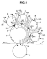
Fig. 1 is a side view showing an array of cylinders of a gravure offset printing press according to the first embodiment of the present invention; and -
Fig. 2 is a side view showing an array of cylinders of a gravure offset printing press according to the first embodiment of the present invention. - The first embodiment of the present invention will be described with reference to
Fig. 1 . Asilicone blanket cylinder 2 with a diameter which is larger than that of an impression cylinder 1 and double that of gravure plate cylinders (to be described later) is opposed to the impression cylinder 1, as shown inFig. 1 . Atransfer object 3 is supplied between the impression cylinder 1 and theblanket cylinder 2, and ink is transferred from theblanket cylinder 2 onto thetransfer object 3 at a transfer position G at which the impression cylinder 1 andblanket cylinder 2 are opposed to each other. - Four
gravure plate cylinders 5 to 8 are arranged on theblanket cylinder 2 from the upstream side to the downstream side in its rotation direction so as to come into contact with the circumferential surface of theblanket cylinder 2. Thegravure plate cylinders 5 to 8 with the same diameter sequentially come into contact with the circumferential surface of theblanket cylinder 2 at contact positions A, B, C, and D, respectively. - Image
areas including recesses 5a to 8a to be filled withinks 10A to 10D containing silver paste are formed on the circumferential surfaces of thegravure plate cylinders 5 to 8.Doctor blades 5b to 8b fill therecesses 5a to 8a with theinks 10A to 10D supplied from an ink supply device (not shown) onto the circumferential surfaces of thegravure plate cylinders 5 to 8. At the same time, the doctor blades 5b to 8b scrape away superfluous inks adhering on the circumferential surfaces of thegravure plate cylinders 5 to 8. - The
recesses 5a to 8a in thegravure plate cylinder 5 have widths W1 to W4, respectively, in their circumferential directions. The widths W1 to W4 of therecesses 5a to 8a satisfy a relation:
The widths W1 to W4 of therecesses 5a to 8a determine the widths of lines running in the plate cylinder axis directions in the image areas. Note thatFig. 1 shows with exaggeration the widths W1 to W4 of therecesses 5a to 8a to be larger than their actual widths for the sake of descriptive convenience. - Let L1 be the circumferential length of the
blanket cylinder 2 between the contact position A between thegravure plate cylinder 5 and theblanket cylinder 2, and the transfer position G at which theinks 10A to 10D are transferred from theblanket cylinder 2 onto thetransfer object 3. Let L2 be the circumferential length of theblanket cylinder 2 between the contact position B between thegravure plate cylinder 6 and theblanket cylinder 2, and the transfer position G. Let L3 be the circumferential length of theblanket cylinder 2 between the contact position C between thegravure plate cylinder 7 and theblanket cylinder 2, and the transfer position G. Let L4 be the circumferential length of theblanket cylinder 2 between the contact position D between thegravure plate cylinder 8 and theblanket cylinder 2, and the transfer position G. The contact positions A to D are set such that the circumferential lengths L1 to L4 of theblanket cylinder 2 satisfy:
- That is, the contact positions A to D between the
gravure plate cylinders 5 to 8 and theblanket cylinder 2 are set such that a gravure plate cylinder including a recess with a relatively large width is positioned upstream, in the rotation direction of theblanket cylinder 2, of a gravure plate cylinder including a recess with a relatively small width. In this case, thegravure plate cylinders 5 to 7 are positioned upstream of thegravure plate cylinder 8 in the rotation direction of theblanket cylinder 2. Thegravure plate cylinders gravure plate cylinder 7 in the rotation direction of theblanket cylinder 2. Thegravure plate cylinder 5 is positioned upstream of thegravure plate cylinder 6 in the rotation direction of theblanket cylinder 2. - As a method of setting the contact positions A to D, first, the circumferential lengths L1 to L4 are calculated in proportion to the widths W1 to W4 of the
recesses 5a to 8a to temporarily determine the contact positions A to D. Next, the contact positions A to D are finely adjusted so that theinks 10A to 10D have the same viscosity characteristics at the transfer position G. In this case, if optimum contact positions A to D can be obtained based simply on the proportionality between the widths W1 to W4 of therecesses 5a to 8a and the circumferential lengths L1 to L4, there is no need to finely adjust the contact positions A to D. - Upon setting the circumferential lengths L1 to L4, the
inks 10A to 10D transferred from thegravure plate cylinders 5 to 8 onto theblanket cylinder 2 are further transferred from theblanket cylinder 2 onto thetransfer object 3 while they are kept in nearly the same half-dry state (semidry state) and have nearly the same cohesive force at the transfer position G, in accordance with the widths W1 to W4 of therecesses 5a to 8a. Setting the circumferential lengths L1 to L4 amounts to setting the times taken to transfer theinks 10A to 10D onto thetransfer object 3 at the transfer position G after they are transferred onto theblanket cylinder 2. During the set times, theinks 10A to 10D transferred onto theblanket cylinder 2 at the contact positions A to D are kept in nearly the same half-dry state in accordance with their amounts at the transfer position G and are thereupon further transferred onto thetransfer object 3. - In the half-dry state, the
inks 10A to 10D have a predetermined cohesive force or adhesive force with which they are transferred onto thetransfer object 3 without remaining in therecesses 5a to 8a. Accordingly, theinks 10A to 10D in this half-dry state have a predetermined viscosity (coefficient of viscosity) intermediate between a fluid state as typified by a watery state and a completely dry state. - A printing operation in a gravure offset printing press with the above-mentioned arrangement will be described next. The doctor blades 5b to 8b fill the
recesses 5a to 8a with the inks supplied from the ink supply device (not shown) onto the circumferential surfaces of thegravure plate cylinders 5 to 8. - The
inks 10A to 10D which fill therecesses 5a to 8a are transferred onto theblanket cylinder 2 at the contact positions A to D, respectively. At this time, the circumferential surface of theblanket cylinder 2 partially enters therecesses 5a to 8a because theblanket cylinder 2 is made of elastically deformable silicone. Therefore, theblanket cylinder 2 which has entered therecesses 5a to 8a comes into tight contact with theinks 10A to 10D which fill therecesses 5a to 8a, thereby reliably transferring theinks 10A to 10D onto theblanket cylinder 2. - Solvents contained in the
inks 10A to 10D transferred onto theblanket cylinder 2 spontaneously evaporate while moving to the transfer position G. Therefore, theinks 10A to 10D dry to nearly the same half-dry state and have nearly the same cohesive force at the transfer position G. As a result, high-resolution printing can be performed by theinks 10A to 10D transferred onto thetransfer object 3 with nearly the same cohesive force at the transfer position G. - An application example of the first embodiment will be described. In this application example, the
inks 10A to 10D to be supplied from thegravure plate cylinders 5 to 8 have different properties (types), in addition to setting of the circumferential lengths L1 to L4 according to the first embodiment. More specifically, solvents with different boiling points can be used as solvents to be added to the inks, or the mixture ratio between an ink component and a solvent can be changed. Thus, theinks 10A to 10D transferred at the transfer position G can more accurately be kept in nearly the same half-dry state (cohesion state). - In the first embodiment described above, because the
inks 10A to 10D which fill therecesses 5a to 8a in thegravure plate cylinders 5 to 8 that form image areas with different line widths dry to have nearly the same rheological characteristics at the transfer position G, no variation in cohesive force of the ink itself occurs. Thus, the transfer forces with which theinks 10A to 10D are transferred onto thetransfer object 3 become nearly uniform, so the printing quality improves free from a variation in printing. As a result, various kinds of printing patterns with different line widths can be printed at once. - Also, because the
inks 10A to 10D transferred onto theblanket cylinder 2 are kept in a half-dry state while moving to the transfer position G, a predetermined adhesive force can be obtained upon transferring them onto thetransfer object 3. This improves the adhesive forces (cohesive forces) of theinks 10A to 10D with respect to thetransfer object 3. As a result, theinks 10A to 10D can be reliably transferred onto thetransfer object 3, so transfer failures reduce and the printing quality improves. - Moreover, because the surface energy of the
blanket cylinder 2 decreases due to factors associated with the properties of silicone, the separation characteristics of theinks 10A to 10D upon transferring them onto thetransfer object 3 improve. This smoothens the surfaces of theinks 10A to 10D transferred onto thetransfer object 3, so a high-quality printing product can be obtained. - The second embodiment of the present invention will be described with reference to
Fig. 2 . In the first embodiment, the circumferential lengths L1 to L4 are set to obtain the contact positions A to D in accordance with the widths W1 to W4 of therecesses 5a to 8a in thegravure plate cylinders 5 to 8 in their circumferential directions. In the second embodiment, the circumferential lengths L1 to L4 are set in accordance with the cross-sectional areas S1 to S4 ofrecesses 5a to 8a ingravure plate cylinders 5 to 8 in their circumferential directions, as shown inFig. 2 . That is, thegravure plate cylinders 5 to 8 are provided on ablanket cylinder 2 such that therecesses 5a to 8a with the cross-sectional areas S1 to S4 are arranged from the upstream side in descending order of cross-sectional area. According to the second embodiment, the circumferential lengths L1 to L4 are precisely set based on the amounts ofinks 10A to 10D in therecesses 5a to 8a. - Although the entire blanket cylinder is made of silicone in each of the above-described embodiments, a blanket cylinder having a silicone blanket wound around its surface or a blanket cylinder on which a silicone film is formed may be used. Any blanket cylinder can be used as long as at least the portions onto which the inks are transferred from the gravure plate cylinders are formed from silicone. Also, the present invention is not limited to the
silicone blanket cylinder 2, and a blanket cylinder made of PTFE (polytetrafluoroethylene) or PVDF (polyvinylidene fluoride) may be used. Again, any blanket cylinder can be used as long as the cylinder surface is formed from a material with a low surface energy and good separation characteristics. - As has been described above, according to the present invention, the inks transferred onto the printing object can have a predetermined, nearly uniform transfer force, so various kinds of printing patterns can be printed at once.
Claims (9)
- A gravure offset printing press including
a first gravure plate cylinder (8) including, on a circumferential surface thereof, a first recess (8a) to be filled with ink (10D),
at least one second gravure plate cylinder (5 - 7) including, on a circumferential surface thereof, a second recess (5a - 7a) which is to be filled with ink (10A - 10C) and has a width (W1 - W3) in a circumferential direction thereof, that is larger than that (W4) of the first recess,
a blanket cylinder (2) which comes into contact with the first gravure plate cylinder and the second gravure plate cylinder to receive the inks from the first gravure plate cylinder and the second gravure plate cylinder, and
an impression cylinder (1) which is opposed to the blanket cylinder with a printing object (3) sandwiched between them, the printing object onto which the inks are transferred from the blanket cylinder, characterized in that
a contact position (B - D) between the second gravure plate cylinder and the blanket cylinder is located upstream, in a rotation direction of the blanket cylinder, of a contact position (A) between the first gravure plate cylinder and the blanket cylinder. - An apparatus according to claim 1, wherein
the contact positions between the first gravure plate cylinder and the second gravure plate cylinder, respectively, and the blanket cylinder are set in accordance with one of widths and cross-sectional areas of the recesses in the first gravure plate cylinder and the second gravure plate cylinder, respectively. - An apparatus according to claim 2, wherein
circumferential lengths of the blanket cylinder from the contact positions between the first gravure plate cylinder and the second gravure plate cylinder, respectively, and the blanket cylinder to a transfer position (G) at which the inks are transferred from the blanket cylinder onto a transfer object are proportional to one of the widths and the cross-sectional areas of the recesses in the first gravure plate cylinder and the second gravure plate cylinder, respectively. - An apparatus according to claim 1, wherein
the inks transferred from the first gravure plate cylinder and the second gravure plate cylinder onto the blanket cylinder at the respective contact positions are further transferred from the blanket cylinder onto the printing object while having a nearly identical degree of dryness. - An apparatus according to claim 1, wherein
the recesses in the first gravure plate cylinder and the second gravure plate cylinder, respectively, are filled with inks having different properties. - An apparatus according to claim 1, wherein
a surface of the blanket cylinder is made of a material with a low surface energy. - An apparatus according to claim 1, wherein
the inks which fill the recesses in the first gravure plate cylinder and the second gravure plate cylinder, respectively, contain silver paste. - An apparatus according to claim 1, wherein
a plurality of the second gravure plate cylinders are provided including the second recesses which have different widths, and
a contact position (B - D) between the second gravure plate cylinder including the second recess with a relatively large width and the blanket cylinder is located upstream, in a rotation direction of the blanket cylinder, of a contact position between the gravure plate cylinder including the second recess with a relatively small width and the blanket cylinder. - A gravure offset printing press including
a plurality of gravure plate cylinders (5 - 8) including, on circumferential surfaces thereof, recesses (5a - 8a) which are to be filled with inks (10A - 10D) and have different widths (W1 - W4) in circumferential directions thereof,
a blanket cylinder (2) which comes into contact with the plurality of gravure plate cylinders to receive the inks from the plurality of gravure plate cylinders, and
an impression cylinder (1) which is opposed to the blanket cylinder with a printing object (3) sandwiched between them, the printing object onto which the inks are transferred from the blanket cylinder, characterized in that
a contact position (A - D) between a gravure plate cylinder including a recess with a relatively large width and the blanket cylinder is located upstream, in a rotation direction of the blanket cylinder, of a contact position between a gravure plate cylinder including a recess with a relatively small width and the blanket cylinder.
Applications Claiming Priority (1)
| Application Number | Priority Date | Filing Date | Title |
|---|---|---|---|
| JP2010114005A JP5438593B2 (en) | 2010-05-18 | 2010-05-18 | Gravure offset printing machine |
Publications (1)
| Publication Number | Publication Date |
|---|---|
| EP2388137A1 true EP2388137A1 (en) | 2011-11-23 |
Family
ID=44318695
Family Applications (1)
| Application Number | Title | Priority Date | Filing Date |
|---|---|---|---|
| EP11004079A Withdrawn EP2388137A1 (en) | 2010-05-18 | 2011-05-17 | Gravure offset printing press |
Country Status (6)
| Country | Link |
|---|---|
| US (1) | US20110283905A1 (en) |
| EP (1) | EP2388137A1 (en) |
| JP (1) | JP5438593B2 (en) |
| KR (1) | KR20110127083A (en) |
| CN (1) | CN102248748A (en) |
| TW (1) | TW201200368A (en) |
Families Citing this family (18)
| Publication number | Priority date | Publication date | Assignee | Title |
|---|---|---|---|---|
| JP5405676B2 (en) * | 2011-02-14 | 2014-02-05 | 順 阪本 | Printing machine, printing apparatus and printing method |
| BR102012016393A2 (en) | 2012-07-02 | 2015-04-07 | Rexam Beverage Can South America S A | Can printing device, can printing process, printed can and blanket |
| JP6112502B2 (en) * | 2012-10-05 | 2017-04-12 | 株式会社小森コーポレーション | Gravure offset printing machine |
| JP2014133372A (en) * | 2013-01-11 | 2014-07-24 | Fujikura Ltd | Printer, printing method, optical fiber and optical fiber cable |
| ES2842224T3 (en) | 2013-06-11 | 2021-07-13 | Ball Corp | Printing procedure using soft photopolymer plates |
| US9555616B2 (en) | 2013-06-11 | 2017-01-31 | Ball Corporation | Variable printing process using soft secondary plates and specialty inks |
| JP6233807B2 (en) * | 2014-02-26 | 2017-11-22 | 株式会社小森コーポレーション | Gravure printing machine and operation method of gravure printing machine |
| US10086602B2 (en) | 2014-11-10 | 2018-10-02 | Rexam Beverage Can South America | Method and apparatus for printing metallic beverage container bodies |
| PL3028856T3 (en) | 2014-12-04 | 2019-10-31 | Ball Beverage Packaging Europe Ltd | Printing apparatus |
| US10549921B2 (en) | 2016-05-19 | 2020-02-04 | Rexam Beverage Can Company | Beverage container body decorator inspection apparatus |
| US11034145B2 (en) | 2016-07-20 | 2021-06-15 | Ball Corporation | System and method for monitoring and adjusting a decorator for containers |
| RU2701243C1 (en) | 2016-07-20 | 2019-09-25 | Бол Корпорейшн | System and method of adjusting paint assembly of printing machine on cylinders and tubes |
| US10739705B2 (en) | 2016-08-10 | 2020-08-11 | Ball Corporation | Method and apparatus of decorating a metallic container by digital printing to a transfer blanket |
| MX395129B (en) | 2016-08-10 | 2025-03-24 | Ball Corp | METHOD AND APPARATUS FOR DECORATING A METAL CONTAINER BY DIGITAL PRINTING ON A TRANSFER BLANKET. |
| JP6386119B2 (en) * | 2017-03-07 | 2018-09-05 | 株式会社小森コーポレーション | Gravure offset printing machine |
| CN108582970A (en) * | 2018-04-21 | 2018-09-28 | 海宁市天祥包装机械厂 | Intaglio press |
| CA3125637C (en) | 2019-01-11 | 2023-10-24 | Ball Corporation | Closed-loop feedback printing system |
| CN109572155B (en) * | 2019-01-28 | 2020-12-15 | 广东法拉利彩印实业有限公司 | A gravure printing machine |
Citations (1)
| Publication number | Priority date | Publication date | Assignee | Title |
|---|---|---|---|---|
| JP2005186597A (en) | 2003-12-26 | 2005-07-14 | Sumitomo Rubber Ind Ltd | Method for manufacturing conductive pattern |
Family Cites Families (5)
| Publication number | Priority date | Publication date | Assignee | Title |
|---|---|---|---|---|
| US1604082A (en) * | 1924-11-10 | 1926-10-19 | James T Robinson | Apparatus for offset photogravure printing |
| JPS61284441A (en) * | 1985-06-11 | 1986-12-15 | Takahane Sangyo Kk | Offset printing press and printing method |
| EP0343105B1 (en) * | 1988-05-18 | 1993-12-15 | De La Rue Giori S.A. | Multicolour rotary press for simultaneous perfecting |
| CH675985A5 (en) * | 1988-07-13 | 1990-11-30 | De La Rue Giori Sa | |
| JP2004111822A (en) * | 2002-09-20 | 2004-04-08 | Sumitomo Rubber Ind Ltd | Method for manufacturing translucent electromagnetic wave shielding member |
-
2010
- 2010-05-18 JP JP2010114005A patent/JP5438593B2/en not_active Expired - Fee Related
-
2011
- 2011-05-12 US US13/106,777 patent/US20110283905A1/en not_active Abandoned
- 2011-05-13 CN CN2011101283945A patent/CN102248748A/en active Pending
- 2011-05-17 TW TW100117183A patent/TW201200368A/en unknown
- 2011-05-17 KR KR1020110046342A patent/KR20110127083A/en not_active Ceased
- 2011-05-17 EP EP11004079A patent/EP2388137A1/en not_active Withdrawn
Patent Citations (1)
| Publication number | Priority date | Publication date | Assignee | Title |
|---|---|---|---|---|
| JP2005186597A (en) | 2003-12-26 | 2005-07-14 | Sumitomo Rubber Ind Ltd | Method for manufacturing conductive pattern |
Also Published As
| Publication number | Publication date |
|---|---|
| JP2011240567A (en) | 2011-12-01 |
| JP5438593B2 (en) | 2014-03-12 |
| TW201200368A (en) | 2012-01-01 |
| CN102248748A (en) | 2011-11-23 |
| KR20110127083A (en) | 2011-11-24 |
| US20110283905A1 (en) | 2011-11-24 |
Similar Documents
| Publication | Publication Date | Title |
|---|---|---|
| US20110283905A1 (en) | Gravure offset printing press | |
| US9440426B2 (en) | Ink proofing system | |
| US4445433A (en) | Method and apparatus for variable density inking | |
| US20110259220A1 (en) | Gravure printing press | |
| US20020014171A1 (en) | Short inking unit | |
| JP2008247047A (en) | Method for adjusting quantity of ink and apparatus for printing printed matter to be printed | |
| US6343550B1 (en) | Flexographic printing apparatus and method | |
| DE4401362C2 (en) | Process and rotary printing machine for indirect gravure printing | |
| EP2604430B1 (en) | Flexographic printing process | |
| DE2445152A1 (en) | Rotogravure printing device | |
| US7841277B1 (en) | Layered structure of a printing plate for printing solid areas and highlight areas | |
| CN102416760B (en) | To version measuring cell | |
| JP2000255025A (en) | Offset printing apparatus, offset printing method, and high-definition pattern substrate obtained using the same | |
| US3965819A (en) | Ink ductor system | |
| DE69915957T2 (en) | SELECTIVE FLEXODRUCK WITH A MOVABLE ANILOX ROLLER | |
| CA2349962C (en) | A doctor blade for the removal of dampening medium | |
| JP2009132130A (en) | Ink coating apparatus and ink coating method in gravure printing machine | |
| US20100326301A1 (en) | Variable Ink Metering and Delivery System for Flexographic Printing | |
| JP5607421B2 (en) | Gravure offset printing machine | |
| DE4328027A1 (en) | Rotary printing machine for making newspapers | |
| US8711399B2 (en) | Adaptive take-off strips for smoothing ink consumption | |
| JP2007331219A (en) | Printing machine and printing method | |
| DE102015104469A1 (en) | Method for operating a printing machine | |
| DE102017222094A1 (en) | Printing unit of a printing press and method for operating a printing unit of a printing press | |
| DE523274C (en) | Device for removing any ink residue from the printing plate of the forme cylinder of a rotogravure printing machine |
Legal Events
| Date | Code | Title | Description |
|---|---|---|---|
| AK | Designated contracting states |
Kind code of ref document: A1 Designated state(s): AL AT BE BG CH CY CZ DE DK EE ES FI FR GB GR HR HU IE IS IT LI LT LU LV MC MK MT NL NO PL PT RO RS SE SI SK SM TR |
|
| AX | Request for extension of the european patent |
Extension state: BA ME |
|
| PUAI | Public reference made under article 153(3) epc to a published international application that has entered the european phase |
Free format text: ORIGINAL CODE: 0009012 |
|
| 17P | Request for examination filed |
Effective date: 20120516 |
|
| GRAP | Despatch of communication of intention to grant a patent |
Free format text: ORIGINAL CODE: EPIDOSNIGR1 |
|
| STAA | Information on the status of an ep patent application or granted ep patent |
Free format text: STATUS: THE APPLICATION IS DEEMED TO BE WITHDRAWN |
|
| 18D | Application deemed to be withdrawn |
Effective date: 20121124 |