EP2388037A1 - Respiratory mask - Google Patents
Respiratory mask Download PDFInfo
- Publication number
- EP2388037A1 EP2388037A1 EP11006459A EP11006459A EP2388037A1 EP 2388037 A1 EP2388037 A1 EP 2388037A1 EP 11006459 A EP11006459 A EP 11006459A EP 11006459 A EP11006459 A EP 11006459A EP 2388037 A1 EP2388037 A1 EP 2388037A1
- Authority
- EP
- European Patent Office
- Prior art keywords
- mask according
- breathing
- mask
- gap
- exhalation
- Prior art date
- Legal status (The legal status is an assumption and is not a legal conclusion. Google has not performed a legal analysis and makes no representation as to the accuracy of the status listed.)
- Granted
Links
- 230000000241 respiratory effect Effects 0.000 title claims description 32
- 230000029058 respiratory gaseous exchange Effects 0.000 claims abstract description 45
- 125000006850 spacer group Chemical group 0.000 claims description 10
- 230000007704 transition Effects 0.000 claims description 7
- 230000000295 complement effect Effects 0.000 claims description 4
- 230000000717 retained effect Effects 0.000 claims 1
- 239000011324 bead Substances 0.000 description 5
- 238000010276 construction Methods 0.000 description 4
- 210000001061 forehead Anatomy 0.000 description 4
- 238000000034 method Methods 0.000 description 4
- 238000003780 insertion Methods 0.000 description 3
- 230000037431 insertion Effects 0.000 description 3
- 239000000463 material Substances 0.000 description 3
- 238000005516 engineering process Methods 0.000 description 2
- 230000000284 resting effect Effects 0.000 description 2
- 239000007779 soft material Substances 0.000 description 2
- 230000006735 deficit Effects 0.000 description 1
- 230000001419 dependent effect Effects 0.000 description 1
- 238000009795 derivation Methods 0.000 description 1
- 210000003128 head Anatomy 0.000 description 1
- 230000003993 interaction Effects 0.000 description 1
- 238000002386 leaching Methods 0.000 description 1
- 238000004519 manufacturing process Methods 0.000 description 1
- 230000000873 masking effect Effects 0.000 description 1
- 238000007789 sealing Methods 0.000 description 1
- 239000011343 solid material Substances 0.000 description 1
Images


Classifications
-
- A—HUMAN NECESSITIES
- A61—MEDICAL OR VETERINARY SCIENCE; HYGIENE
- A61M—DEVICES FOR INTRODUCING MEDIA INTO, OR ONTO, THE BODY; DEVICES FOR TRANSDUCING BODY MEDIA OR FOR TAKING MEDIA FROM THE BODY; DEVICES FOR PRODUCING OR ENDING SLEEP OR STUPOR
- A61M16/00—Devices for influencing the respiratory system of patients by gas treatment, e.g. mouth-to-mouth respiration; Tracheal tubes
- A61M16/08—Bellows; Connecting tubes ; Water traps; Patient circuits
- A61M16/0816—Joints or connectors
- A61M16/0825—Joints or connectors with ball-sockets
-
- A—HUMAN NECESSITIES
- A61—MEDICAL OR VETERINARY SCIENCE; HYGIENE
- A61M—DEVICES FOR INTRODUCING MEDIA INTO, OR ONTO, THE BODY; DEVICES FOR TRANSDUCING BODY MEDIA OR FOR TAKING MEDIA FROM THE BODY; DEVICES FOR PRODUCING OR ENDING SLEEP OR STUPOR
- A61M16/00—Devices for influencing the respiratory system of patients by gas treatment, e.g. mouth-to-mouth respiration; Tracheal tubes
- A61M16/0003—Accessories therefor, e.g. sensors, vibrators, negative pressure
-
- A—HUMAN NECESSITIES
- A61—MEDICAL OR VETERINARY SCIENCE; HYGIENE
- A61M—DEVICES FOR INTRODUCING MEDIA INTO, OR ONTO, THE BODY; DEVICES FOR TRANSDUCING BODY MEDIA OR FOR TAKING MEDIA FROM THE BODY; DEVICES FOR PRODUCING OR ENDING SLEEP OR STUPOR
- A61M16/00—Devices for influencing the respiratory system of patients by gas treatment, e.g. mouth-to-mouth respiration; Tracheal tubes
- A61M16/06—Respiratory or anaesthetic masks
- A61M16/0605—Means for improving the adaptation of the mask to the patient
- A61M16/0616—Means for improving the adaptation of the mask to the patient with face sealing means comprising a flap or membrane projecting inwards, such that sealing increases with increasing inhalation gas pressure
- A61M16/0622—Means for improving the adaptation of the mask to the patient with face sealing means comprising a flap or membrane projecting inwards, such that sealing increases with increasing inhalation gas pressure having an underlying cushion
-
- A—HUMAN NECESSITIES
- A61—MEDICAL OR VETERINARY SCIENCE; HYGIENE
- A61M—DEVICES FOR INTRODUCING MEDIA INTO, OR ONTO, THE BODY; DEVICES FOR TRANSDUCING BODY MEDIA OR FOR TAKING MEDIA FROM THE BODY; DEVICES FOR PRODUCING OR ENDING SLEEP OR STUPOR
- A61M16/00—Devices for influencing the respiratory system of patients by gas treatment, e.g. mouth-to-mouth respiration; Tracheal tubes
- A61M16/06—Respiratory or anaesthetic masks
- A61M16/0605—Means for improving the adaptation of the mask to the patient
- A61M16/0633—Means for improving the adaptation of the mask to the patient with forehead support
- A61M16/0638—Means for improving the adaptation of the mask to the patient with forehead support in the form of a pivot
-
- A—HUMAN NECESSITIES
- A61—MEDICAL OR VETERINARY SCIENCE; HYGIENE
- A61M—DEVICES FOR INTRODUCING MEDIA INTO, OR ONTO, THE BODY; DEVICES FOR TRANSDUCING BODY MEDIA OR FOR TAKING MEDIA FROM THE BODY; DEVICES FOR PRODUCING OR ENDING SLEEP OR STUPOR
- A61M16/00—Devices for influencing the respiratory system of patients by gas treatment, e.g. mouth-to-mouth respiration; Tracheal tubes
- A61M16/06—Respiratory or anaesthetic masks
- A61M16/0605—Means for improving the adaptation of the mask to the patient
- A61M16/0633—Means for improving the adaptation of the mask to the patient with forehead support
- A61M16/0644—Means for improving the adaptation of the mask to the patient with forehead support having the means for adjusting its position
- A61M16/065—Means for improving the adaptation of the mask to the patient with forehead support having the means for adjusting its position in the form of a pivot
-
- A—HUMAN NECESSITIES
- A61—MEDICAL OR VETERINARY SCIENCE; HYGIENE
- A61M—DEVICES FOR INTRODUCING MEDIA INTO, OR ONTO, THE BODY; DEVICES FOR TRANSDUCING BODY MEDIA OR FOR TAKING MEDIA FROM THE BODY; DEVICES FOR PRODUCING OR ENDING SLEEP OR STUPOR
- A61M16/00—Devices for influencing the respiratory system of patients by gas treatment, e.g. mouth-to-mouth respiration; Tracheal tubes
- A61M16/22—Carbon dioxide-absorbing devices ; Other means for removing carbon dioxide
-
- A—HUMAN NECESSITIES
- A61—MEDICAL OR VETERINARY SCIENCE; HYGIENE
- A61M—DEVICES FOR INTRODUCING MEDIA INTO, OR ONTO, THE BODY; DEVICES FOR TRANSDUCING BODY MEDIA OR FOR TAKING MEDIA FROM THE BODY; DEVICES FOR PRODUCING OR ENDING SLEEP OR STUPOR
- A61M16/00—Devices for influencing the respiratory system of patients by gas treatment, e.g. mouth-to-mouth respiration; Tracheal tubes
- A61M16/0003—Accessories therefor, e.g. sensors, vibrators, negative pressure
- A61M2016/0027—Accessories therefor, e.g. sensors, vibrators, negative pressure pressure meter
-
- A—HUMAN NECESSITIES
- A61—MEDICAL OR VETERINARY SCIENCE; HYGIENE
- A61M—DEVICES FOR INTRODUCING MEDIA INTO, OR ONTO, THE BODY; DEVICES FOR TRANSDUCING BODY MEDIA OR FOR TAKING MEDIA FROM THE BODY; DEVICES FOR PRODUCING OR ENDING SLEEP OR STUPOR
- A61M2205/00—General characteristics of the apparatus
- A61M2205/14—Detection of the presence or absence of a tube, a connector or a container in an apparatus
-
- A—HUMAN NECESSITIES
- A61—MEDICAL OR VETERINARY SCIENCE; HYGIENE
- A61M—DEVICES FOR INTRODUCING MEDIA INTO, OR ONTO, THE BODY; DEVICES FOR TRANSDUCING BODY MEDIA OR FOR TAKING MEDIA FROM THE BODY; DEVICES FOR PRODUCING OR ENDING SLEEP OR STUPOR
- A61M2205/00—General characteristics of the apparatus
- A61M2205/33—Controlling, regulating or measuring
- A61M2205/3327—Measuring
-
- A—HUMAN NECESSITIES
- A61—MEDICAL OR VETERINARY SCIENCE; HYGIENE
- A61M—DEVICES FOR INTRODUCING MEDIA INTO, OR ONTO, THE BODY; DEVICES FOR TRANSDUCING BODY MEDIA OR FOR TAKING MEDIA FROM THE BODY; DEVICES FOR PRODUCING OR ENDING SLEEP OR STUPOR
- A61M2205/00—General characteristics of the apparatus
- A61M2205/42—Reducing noise
-
- A—HUMAN NECESSITIES
- A61—MEDICAL OR VETERINARY SCIENCE; HYGIENE
- A61M—DEVICES FOR INTRODUCING MEDIA INTO, OR ONTO, THE BODY; DEVICES FOR TRANSDUCING BODY MEDIA OR FOR TAKING MEDIA FROM THE BODY; DEVICES FOR PRODUCING OR ENDING SLEEP OR STUPOR
- A61M2205/00—General characteristics of the apparatus
- A61M2205/60—General characteristics of the apparatus with identification means
- A61M2205/6045—General characteristics of the apparatus with identification means having complementary physical shapes for indexing or registration purposes
Landscapes
- Health & Medical Sciences (AREA)
- Emergency Medicine (AREA)
- Pulmonology (AREA)
- Engineering & Computer Science (AREA)
- Anesthesiology (AREA)
- Biomedical Technology (AREA)
- Heart & Thoracic Surgery (AREA)
- Hematology (AREA)
- Life Sciences & Earth Sciences (AREA)
- Animal Behavior & Ethology (AREA)
- General Health & Medical Sciences (AREA)
- Public Health (AREA)
- Veterinary Medicine (AREA)
- Respiratory Apparatuses And Protective Means (AREA)
- Pharmaceuticals Containing Other Organic And Inorganic Compounds (AREA)
Abstract
Description
Die Erfindung betrifft eine Atemmaske mit einem Maskenkörper und einem gelenkigen Anschlußstück, welches mit einem Atemschlauch verbindbar ist.The invention relates to a breathing mask with a mask body and an articulated connection piece, which is connectable to a breathing tube.
Atemmasken werden beispielsweise im Zusammenhang mit Beatmungsgeräten verwendet, um Atemgas zum Patienten zu leiten und eine Ableitung des ausgeatmeten Atemgases zu unterstützen. Die Atemmaske ist typischerweise über den Atemschlauch mit dem Beatmungsgerät verbunden.For example, respirators are used in conjunction with ventilators to direct respiratory gas to the patient and assist in the discharge of exhaled respiratory gas. The breathing mask is typically connected to the ventilator via the breathing tube.
Als Nachteil bei den bereits bekannten Atemmasken erweist es sich, dass beim Ausatmen durch den Maskenkörper und den Beatmungsschlauch mit einer für den Patienten und die Umgebung unangenehmen akustischen Beeinträchtigung zu rechnen ist und darüber hinaus der ausgeatmete Luftstrom einen am Patienten entlang streichenden kühlen Luftzug hervorruft. Aufgabe der vorliegenden Erfindung ist es, eine komfortable Gestaltung einer Atemmaske bereitzustellen, bei der die Beeinträchtigung des Patienten durch ausgeatmete Luft weitgehend vermieden wird.A disadvantage of the already known breathing masks, it turns out that when exhaling through the mask body and the breathing tube to expect a unpleasant for the patient and the environment acoustic interference and, moreover, the exhaled airflow causes a cool draft of air passing along the patient. The object of the present invention is to provide a comfortable design of a breathing mask, in which the impairment of the patient by exhaled air is largely avoided.
Diese Aufgabe wird erfindungsgemäß dadurch gelöst, dass mindestens zwei Bauteile der Atemmaske toleranzfrei miteinander verbunden sind.This object is achieved in that at least two components of the breathing mask are connected together without tolerance.
Gemäß einer weiteren Ausführungsform ist insbesondere in Kombination mit einer Atemmaske mit einem Maskenkörper und einem gelenkigen Anschlussstück, welches mit einem Atemschlauch verbindbar ist, auch daran gedacht,dass im Bereich des Maskenkörpers, bevorzugt im Bereich eines das gelenkige Anschlußstück aufnehmenden Anschlusses am Maskenkörper, mindestens ein Ausatemspalt angeordnet ist.According to a further embodiment, in particular in combination with a breathing mask with a mask body and an articulated connection piece, which is connectable to a breathing tube, also thought that in the region of the mask body, preferably in the region of the articulated connector receiving terminal on the mask body, at least one Exhalation gap is arranged.
Jedes der in den Unteransprüchen definierten Merkmale und jedes Einzelmerkmal gemäß den Ausführungsbeispielen in der nachfolgenden Beschreibung kann einzeln oder in Kombination miteinander auch mit der Ausführungform gemäß der im vorangegangenen Absatz definierten Konstruktion verwendet werden.Each of the features defined in the subclaims and each individual feature according to the embodiments in the following description may be used individually or in combination with each other also with the embodiment according to the construction defined in the preceding paragraph.
Die erfindungsgemäße Atemmaske, die nicht nur als Einzelteil sondern auch als Element eines ganzen Beatmungsgeräts zu verstehen ist, umfaßt einen Maskenkörper sowie ein gelenkiges Anschlußstück, welches mit einem Atemschlauch verbindbar ist, wobei im Bereich des Übergangs zwischen dem gelenkigen Anschlußstück und einem das gelenkige Anschlußstück aufnehmenden Anschluß am Maskenkörper mindestens ein Ausatemspalt angeordnet ist. Insbesondere die Anordnung des Ausatemspalts zwischen dem Maskenkörper und dem Anschlußstück hält den Geräuschpegel gegenüber anderen Anordnungspositionen gering. Auch die CO2 - Auswaschung wird in dieser Position des Ausatemspalts besonders effektiv durchgeführt. Des Weiteren ist es gerade im Übergangsbereich zwischen Maskenkörper und Anschlußstück möglich, eine große Spaltlänge vorzusehen, die schalltechnisch besonders vorteilhaft ist im Vergleich beispielsweise zu Löchern und kurzen Schlitzen.The breathing mask according to the invention, which is to be understood not only as an individual part but also as an element of a whole ventilator, comprises a mask body and an articulated connection piece, which is provided with a breathing tube is connectable, wherein at least one exhalation gap is arranged in the region of the transition between the articulated connection piece and a connection receiving the articulated connection on the mask body. In particular, the arrangement of the exhalation gap between the mask body and the connector keeps the noise level low with respect to other arrangement positions. The CO 2 - leaching is performed particularly effective in this position of the exhalation. Furthermore, it is just in the transition region between the mask body and fitting possible to provide a large gap length, the sound technology is particularly advantageous compared, for example, to holes and short slots.
Der mindestens eine Ausatemspalt wird bevorzugt von zwei Ausströmflächen begrenzt.The at least one exhalation gap is preferably limited by two outflow areas.
Das gelenkige Anschlußstück ist vorteilhafterweise als Kugelgelenk ausgebildet und liegt an einzelnen Punkten, insbesondere an zwei Punkten, in einem Kugelkäfig des aufnehmenden Anschlusses auf. Auf diese Weise tritt eine geringe Lagerreibung auf und eine leichte Beweglichkeit des angeschlossenen Atemschlauchs ist gewährleistet. Ebenfalls können in einfacher Weise Toleranzen ausgeglichen werden.The articulated connecting piece is advantageously designed as a ball joint and is located at individual points, in particular at two points, in a ball cage of the female terminal. In this way, a low bearing friction occurs and easy mobility of the connected breathing tube is guaranteed. Also tolerances can be compensated in a simple manner.
In einer weiteren vorteilhaften Ausgestaltung der Atemmaske wird der mindestens eine Ausatemspalt von den Ausströmflächen begrenzt, wobei diese sich benachbart zu mindestens einem Distanzelement befinden und dabei spielfrei oder sogar mit Vorspannung zueinander versehen sind. So wird vermieden, dass durch entweichende Luft bei bestehendem Spiel unerwünschte Schwingungen und Resonanzen auftreten. Insbesondere bei einem Ausatemspalt in einem Kugelgelenk ergibt sich nämlich eine große Spaltlänge. Dies könnte sich unter Umständen als schalltechnisch nachteilhaft erweisen, wenn sich im Spalt bewegliche Teile befinden.In a further advantageous embodiment of the breathing mask, the at least one exhalation gap is delimited by the outflow surfaces, wherein these are adjacent to at least one spacer element and are thereby provided free of play or even with bias to one another. This avoids that by escaping air at existing Play unwanted vibrations and resonances occur. In particular, in the case of an exhalation gap in a ball joint, a large gap length results. This could prove to be disadvantageous in terms of sound technology if there are moving parts in the gap.
Der Ausatemspalt zwischen zwei Ausströmflächen kann zudem weitgehend toleranzfrei hergestellt werden, wenn die spaltbildenden Flächen durch eine Vorspannung aneinandergedrückt werden und hierdurch kein Spiel aufweisen, und die Spalthöhe durch Distanzelemente zwischen den Flächen eingestellt wird. Bei einer solchen Konstruktion hängt die Spalthöhe abgesehen von Form- und Lagetoleranzen der spaltbildenden Flächen nur von der Toleranz einer Rippenhöhe als Distanzelement ab. Da typische Rippenhöhen in Ausatemspalten zwischen 0,1 und 0,5 mm liegen, sind Spalttoleranzen von +-0,005 mm und feiner prozeßsicher herstellbar. Flow- und Schallemissionen werden folglich in sehr engen Grenzen gehalten.The exhalation gap between two outflow surfaces can also be made largely tolerance-free, if the gap-forming surfaces are pressed together by a bias and thus have no play, and the gap height is adjusted by spacers between the surfaces. In such a construction, apart from the shape and position tolerances of the gap-forming surfaces, the gap height depends only on the tolerance of a rib height as a spacer element. Since typical rib heights in exhalation gaps are between 0.1 and 0.5 mm, gap tolerances of + -0.005 mm and finer process reliability can be produced. Flow and noise emissions are therefore kept within very narrow limits.
Die Verbindung von Maskenkörper und Anschlußstück kann bevorzugt mit einer mechanischen Kodierung erfolgen. Das hat zum Vorteil, dass eine fehlerhafte Fixierung von Maskenkörper und Anschlußstück zueinander sowie eine fehlerhafte Kombination eines Anschlußstücks mit einem Maskenkörper verhindert werden.The connection of the mask body and connecting piece can preferably take place with a mechanical coding. This has the advantage that a faulty fixation of mask body and fitting to each other and a faulty combination of a fitting with a mask body can be prevented.
Die Fixierung von Maskenkörper und Anschlußstück zueinander erfolgt vorteilhaft über einen Sicherungsring mit einer Schließeinrichtung, beispielsweise mit einem Bajonettverschluß. Durch den Sicherungsring werden auch die Ausatemspalte fixiert, indem zum Beispiel die Ausströmflächen der Atemmaske und komplementäre Ausströmflächen am Sicherungsring gegeneinander vorgespannt werden.The fixation of mask body and fitting to each other is advantageously carried out via a locking ring with a locking device, for example with a bayonet lock. The circlip also fixes the exhalation gaps, for example by biasing the outflow surfaces of the respiratory mask and complementary outflow surfaces against each other on the circlip.
Eine zusätzliche vorteilhafte Ausgestaltung der Atemmaske besteht darin, dass die Ausströmflächen einen Ausströmkanal bilden, der der Atemgasstrom in einem Winkel zwischen 10° und 45°, insbesondere zwischen 20° und 30°, besonders bevorzugt von etwa 25°, bezogen auf eine Ebene frontal zum Gesicht eines Patienten, ableitet. Auf diese Weise wird die ausgeatmete Luft im Wesentlichen schirmförmig vom Patienten weggeleitet und macht sich für den Patienten nicht unangenehm bemerkbar.An additional advantageous embodiment of the breathing mask is that the outflow surfaces form an outflow, the front of the breathing gas at an angle between 10 ° and 45 °, in particular between 20 ° and 30 °, more preferably from about 25 °, based on a plane Face of a patient, derives. In this way, the exhaled air is directed away from the patient substantially umbrella-like and does not make the patient uncomfortable.
Des Weiteren kann der Abströmkanal so ausgebildet sein, dass er ein Ableiten der Ausatemströmung in Richtung der Augenpartie des Patienten ausschließt, da sich ein Luftzug an den Augen als besonders unangenehm erweist.Furthermore, the outflow channel can be designed so that it excludes a derivation of the exhalation flow in the direction of the eye area of the patient, since a draft of air on the eyes proves to be particularly unpleasant.
Weiterhin kann die Atemmaske so ausgebildet sein, dass an den Ausströmungskanal grenzende Oberflächen der Atemmaske aus hartem Kunststoff gefertigt sind und Oberflächen von mit der Hand bedienbaren Elementen der Atemmaske aus weichem Kunststoff gefertigt sind. Auf diese Weise wird einerseits der Atemstrom zuverlässig abgeleitet und andererseits die Handhabbarkeit der Atemmaske erleichtert.Furthermore, the breathing mask may be configured such that surfaces of the breathing mask bordering the outflow channel are made of hard plastic and surfaces of hand-operable elements of the breathing mask are made of soft plastic. In this way, on the one hand the respiratory flow is reliably dissipated and on the other hand facilitates the handling of the breathing mask.
Die Erfindung wird im Folgenden beispielhaft anhand der Figuren erläutert. Es zeigen:
- Fig. 1
- eine als Nasalmaske ausgebildete Atemmaske in perspektivischer Ansicht,
- Fig. 2
- eine Ansicht auf das Innere der Maske aus
Fig. 1 von hinten, - Fig. 3
- eine Ansicht auf das Äußere der Maske aus
Fig. 1 von vorne, - Fig. 4
- den Grundkörper der Maske aus
Fig. 1 in perspektivischer Ansicht, - Fig. 5
- eine Seitenansicht des Grundkörpers,
- Fig. 6
- einen Querschnitt durch die Symmetrieebene des Grundkörpers,
- Fig. 7
- eine Ansicht auf den Sicherungsring von hinten,
- Fig. 8
- eine Ansicht auf den Sicherungsring von vorne,
- Fig. 9
- den Sicherungsring in perspektivischer Ansicht,
- Fig. 10
- den Sicherungsring in seitlicher Ansicht,
- Fig. 11
- den Sicherungsring aus
Fig. 10 im Querschnitt, - Fig. 12
- eine perspektivische Darstellung des Maskengrundkörpers,
- Fig. 13
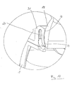
- eine teilweise Darstellung eines vergrößerten Schnittes durch den Maskengrundkörper im Bereich des Kugelgelenkes und
- Fig. 14
- eine vergrößerte Darstellung der Einzelheit XIV in
Fig. 13 .
- Fig. 1
- a breathing mask designed as a nasal mask in a perspective view,
- Fig. 2
- a view on the inside of the mask
Fig. 1 from behind, - Fig. 3
- a view of the exterior of the mask
Fig. 1 from the front, - Fig. 4
- the main body of the mask
Fig. 1 in perspective view, - Fig. 5
- a side view of the body,
- Fig. 6
- a cross section through the plane of symmetry of the body,
- Fig. 7
- a view of the retaining ring from behind,
- Fig. 8
- a view of the retaining ring from the front,
- Fig. 9
- the retaining ring in perspective view,
- Fig. 10
- the retaining ring in lateral view,
- Fig. 11
- the circlip out
Fig. 10 in cross section, - Fig. 12
- a perspective view of the mask body,
- Fig. 13
- a partial view of an enlarged section through the mask body in the region of the ball joint and
- Fig. 14
- an enlarged view of the detail XIV in
Fig. 13 ,
In
In
In
In der
Entlang der Strömungsleitfläche (16) gelangt der Atemgasstrom vom Inneren der Atemmaske nach außen. Nach Verlassen des Ausatemspaltes (14), der die engste Stelle darstellt, verlässt der Atemgasstrom fächerförmig die Atemmaske entlang der langgestreckten Ausströmfläche (10). Dabei verläßt der Atemgasstrom den Ausatemspalt (14) in einem Winkel Alpha, der vorzugsweise zwischen 10° und 45° zur Vertikalen der
In
Die
Die
Die
Die
Die Funktionalität der einzelnen in
Die perspektivische Darstellung in
Die Ausatemspalte (14) sind vorzugsweise derart angeordnet, dass sie in einem der Ausströmfläche (10) zugewandten Bereich des Zentrierringes (13) verlaufen. Hierdurch wird das aus den Ausatemspalten (14) austretende Atemgas unmittelbar in den Bereich der Ausströmfläche (10) geleitet. Nach Verlassen der Ausatemspalten (14) wird der Atemgasstrom an den langgestreckten und breiten Ausströmflächen (10) (28) umgelenkt und strömt diffus und leise, durch den von den Ausströmflächen definierten Ausströmkanal, in die Umgebung ab.The exhalation gaps (14) are preferably arranged such that they extend in a region of the centering ring (13) facing the outflow surface (10). As a result, the breathing gas leaving the exhalation gaps (14) is conducted directly into the region of the outflow surface (10). After leaving the Ausatemspalten (14), the breathing gas flow is deflected at the elongated and wide outflow surfaces (10) (28) and flows diffusely and quietly, through the outflow defined by the outflow, in the environment.
Zur weiteren Erläuterung der Funktionalität der einzelnen Bauelemente wird nunmehr ausgehend von einem demontierten Zustand die auch von einem Patienten in einfacher Weise vornehmbare Montage der Einzelteile erläutert. In einem ersten Schritt werden der aus dem härteren Material bestehende Maskenkörper (1) und der Maskenwulst (2) zusammengefügt. Der Maskenwulst (2) wird hierzu mit einem in den Zeichnungen nicht näher dargestellten U-Profil auf einen Rand des Maskenkörpers (1) aufgeschoben. Im Bereich der Kontaktstelle zwischen Maskenwulst und Maskenkörper befindet sich zumindest ein Hinterschnitt und zumindest ein zum Hinterschnitt komplementärer Vorsprung. Bevorzugt befindet sich der Hinterschnitt im Bereich des weicheren Bauteiles. Das Zusammenwirken von Hinterschnitt und Vorsprung im montierten Zustand sorgt für eine hohe Verbindungsfestigkeit. In einem nächsten Montageschritt kann beispielsweise die Stirnstütze (2) mit einem Schaft (35) in eine Halterung (36) des Maskenkörpers (1) eingesetzt und unter Verwendung zumindest eines Befestigungsmittels (37) arretiert werden. Die Montage der Stirnstütze (5) kann aber auch zu beliebigen anderen Zeitpunkten des Montagevorganges erfolgen.To further explain the functionality of the individual components, the assembly of the individual parts, which can also be performed by a patient in a simple manner, will now be explained starting from a disassembled state. In a first step, the mask body (1) consisting of the harder material and the mask bead (2) are joined together. The mask bead (2) is this with a in the Drawings unspecified U-profile on an edge of the mask body (1) pushed. In the area of the contact point between the mask bead and the mask body there is at least one undercut and at least one projection complementary to the undercut. Preferably, the undercut is located in the region of the softer component. The interaction of undercut and projection in the mounted state ensures a high connection strength. In a next assembly step, for example, the forehead support (2) with a shaft (35) in a holder (36) of the mask body (1) are inserted and locked using at least one fastening means (37). The mounting of the forehead support (5) can also be done at any other time points of the assembly process.
In einem weiteren Montageschritt wird der Sicherungsring (31) ausgehend von der Hülse (4) auf das Anschlußstück (3) aufgeschoben und im Bereich des Kugelgelenkes (18) positioniert. Das Aufschieben des Sicherungsringes (31) erfolgt hierbei in einer Orientierung derart, dass nach einem Abschluss des Aufsetzvorganges die Bajonettzähne (26) in eine der Hülse (4) abgewandte Richtung weisen und das Kugelgelenk (18) vom Kugelkäfig (24) des Sicherungsringes (31) bereichsweise umschlossen ist.In a further assembly step, the retaining ring (31), starting from the sleeve (4) pushed onto the connecting piece (3) and positioned in the region of the ball joint (18). The sliding of the retaining ring (31) takes place in an orientation such that after completion of the Aufsetzvorganges the bayonet teeth (26) in a sleeve (4) facing away from the direction and the ball joint (18) from the ball cage (24) of the locking ring (31 ) is enclosed in areas.
In einem abschließenden Montageschritt wird der Sicherungsring (31) gemeinsam mit dem Anschlußstück (3) im Bereich des Zentrierringes (13) des Maskenkörpers (1) positioniert. Aufgrund der beispielsweise in
Nach dem Einführen der Bajonettzähne (26) in die Aussparungen (37) zwischen den Rippen (11) erfolgt eine Verdrehung des Sicherungsringes (31) relativ zum Maskenkörper (1) derart, dass die Verrastung (12) wirksam wird. Die Verrastung (12) wird vorzugsweise als ein Vorsprung des Sicherungsringes (31) ausgebildet, der in eine korrespondierende Vertiefung des Maskenkörpers (1) eingreift. Grundsätzlich ist aber auch eine umgekehrte Ausbildung denkbar. Ein elastisches Einrasten der Verrastung (12) wird dadurch unterstützt, dass der Sicherungsring (31) aus einem relativ weichen Material ausgebildet ist, so dass der ebenfalls weiche Vorsprung des Sicherungsringes (31) in die Ausnehmung des Maskenkörpers (1) einführbar und auch wieder aus dieser herausdrehbar ist.After the insertion of the bayonet teeth (26) in the recesses (37) between the ribs (11) takes place a rotation of the locking ring (31) relative to the mask body (1) such that the latch (12) is effective. The latch (12) is preferably formed as a projection of the locking ring (31) which engages in a corresponding recess of the mask body (1). In principle, however, a reverse training is conceivable. An elastic latching of the latching (12) is assisted in that the securing ring (31) is formed of a relatively soft material, so that the likewise soft projection of the securing ring (31) into the recess of the mask body (1) insertable and again from this is turn out.
Nach einer den Montagevorgang abschließenden Verdrehung des Sicherungsringes (31) relativ zum Maskenkörper (1) ist der Montagevorgang abgeschlossen. Die Endposition des Sicherungsringes (31) ist durch einen seitlichen Anschlag der Bajonettzähne (26) an den Rippen (11) vorgegeben. Die Bajonettzähne (26) hintergreifen darüber hinaus die Rippen (11), so dass die Gesamtanordnung auch Zugbelastungen standhält. Eine Demontage der Atemmaske erfolgt in umgekehrter Reihenfolge wie vorstehend für die Montage beschrieben.After a final assembly process rotation of the retaining ring (31) relative to the mask body (1) of the assembly process is completed. The end position of the retaining ring (31) is predetermined by a lateral stop of the bayonet teeth (26) on the ribs (11). The bayonet teeth (26) engage beyond the ribs (11), so that the overall arrangement withstands tensile loads. Disassembly of the breathing mask takes place in the reverse order as described above for the assembly.
Die Konstruktion des Sicherungsringes (31) führt dazu, dass der Sicherungsring (31) spielfrei und gegebenenfalls unter Vorspannung auf den Maskenkörper (1) aufgesetzt werden kann. Dies hat zur Folge, dass die Weite des oder der Ausatemspalte (14) nur noch von der Toleranz der Höhe der Distanzrippen (25) abhängig ist. Die Realisierung des Ausatemspaltes (14) erfolgt hierdurch äußerst gleichmäßig und weitgehend toleranzunabhängig. Dies wiederum hat zur Folge, dass die Abströmung des Atemgases durch den Ausatemspalt (14) hindurch und die hierdurch hervorgerufenen Schallemissionen äußerst konstant realisiert werden.The construction of the circlip (31) causes the circlip (31) without play and possibly under bias to the mask body (1) can be placed. This has the consequence that the width of the exhalation or the Ausatemspalte (14) is only dependent on the tolerance of the height of the spacer ribs (25). The realization of the exhalation gap (14) is thereby extremely uniform and largely tolerance-independent. This in turn has the consequence that the outflow of the respiratory gas through the exhalation gap (14) and the sound emissions caused thereby are realized extremely constantly.
Die Konstruktion des Sicherungsringes (31) ermöglicht, dass das Kugelgelenk (18) in den federnden Kugelkäfig (24) des Sicherungsringes (31) eingeführt werden kann und dass der Kugelkäfig (24) das Kugelgelenk zumindest bereichsweise umschließt. Die Fixierung des Kugelgelenks (18) im Kugelkäfig (24) erfolgt dadurch, dass der Zentrierring (13) in die im Sicherungsring befindliche Aufnahme (30) eingeführt wird. Dadurch werden die federnden Elemente des Kugelkäfigs (24) auf der einen Seite durch das Kugelgelenk und auf der gegenüberliegenden Seite durch den Zentrierring (13) begrenzt. Im montierten Zustand ist dadurch das Kugelgelenk im Bereich der Maske fixiert. Die Beweglichkeit des Kugelgelenkes einerseits und die Abdichtung gegenüber dem Atemgas im Bereich zwischen Kugelgelenk und Kugelkäfig wird durch die genaue Dimensionierung und enge Toleranzmaße bestimmt.The construction of the circlip (31) allows the ball joint (18) to be inserted into the resilient ball cage (24) of the circlip (31) and that the ball cage (24) at least partially surrounds the ball joint. The fixation of the ball joint (18) in the ball cage (24) takes place in that the centering ring (13) is inserted into the receiving ring (30) located in the circlip. As a result, the resilient elements of the ball cage (24) are bounded on one side by the ball joint and on the opposite side by the centering ring (13). In the mounted state, this fixes the ball joint in the area of the mask. The mobility of the ball joint on the one hand and the seal against the breathing gas in the area between the ball joint and ball cage is determined by the exact dimensions and tight tolerance dimensions.
Claims (16)
Applications Claiming Priority (2)
| Application Number | Priority Date | Filing Date | Title |
|---|---|---|---|
| DE102004043208 | 2004-09-03 | ||
| EP05787298A EP1838372B1 (en) | 2004-09-03 | 2005-09-01 | Respiratory mask |
Related Parent Applications (2)
| Application Number | Title | Priority Date | Filing Date |
|---|---|---|---|
| EP05787298A Division EP1838372B1 (en) | 2004-09-03 | 2005-09-01 | Respiratory mask |
| EP05787298.8 Division | 2005-09-01 |
Publications (3)
| Publication Number | Publication Date |
|---|---|
| EP2388037A1 true EP2388037A1 (en) | 2011-11-23 |
| EP2388037B1 EP2388037B1 (en) | 2016-07-27 |
| EP2388037B8 EP2388037B8 (en) | 2016-09-21 |
Family
ID=34981456
Family Applications (3)
| Application Number | Title | Priority Date | Filing Date |
|---|---|---|---|
| EP05787298A Active EP1838372B1 (en) | 2004-09-03 | 2005-09-01 | Respiratory mask |
| EP11006459.9A Active EP2388037B8 (en) | 2004-09-03 | 2005-09-01 | Respiratory mask |
| EP05019159.2A Active EP1632262B1 (en) | 2004-09-03 | 2005-09-02 | Respiratory device |
Family Applications Before (1)
| Application Number | Title | Priority Date | Filing Date |
|---|---|---|---|
| EP05787298A Active EP1838372B1 (en) | 2004-09-03 | 2005-09-01 | Respiratory mask |
Family Applications After (1)
| Application Number | Title | Priority Date | Filing Date |
|---|---|---|---|
| EP05019159.2A Active EP1632262B1 (en) | 2004-09-03 | 2005-09-02 | Respiratory device |
Country Status (5)
| Country | Link |
|---|---|
| US (4) | US8887726B2 (en) |
| EP (3) | EP1838372B1 (en) |
| AT (1) | ATE526053T1 (en) |
| DE (1) | DE102005042180A1 (en) |
| WO (1) | WO2006024288A2 (en) |
Families Citing this family (63)
| Publication number | Priority date | Publication date | Assignee | Title |
|---|---|---|---|---|
| US6892729B2 (en) | 2001-11-20 | 2005-05-17 | Fisher & Paykel Healthcare Limited | Patient interfaces |
| WO2004052438A1 (en) | 2002-12-06 | 2004-06-24 | Fisher & Paykel Healthcare Limited | Mouthpiece |
| US8424528B2 (en) * | 2004-01-14 | 2013-04-23 | Weinmann Geräte für Medizin GmbH & Co. KG | Ventilation device |
| WO2005079726A1 (en) | 2004-02-23 | 2005-09-01 | Fisher & Paykel Healthcare Limited | Breathing assistance apparatus |
| US9072852B2 (en) | 2004-04-02 | 2015-07-07 | Fisher & Paykel Healthcare Limited | Breathing assistance apparatus |
| WO2005094928A1 (en) | 2004-04-02 | 2005-10-13 | Fisher & Paykel Healthcare Limited | Breathing assistance apparatus |
| DE102006041038A1 (en) * | 2006-03-31 | 2007-10-04 | Weinmann Geräte für Medizin GmbH + Co. KG | Mask e.g. nasal mask, for e.g. respiration, has structural parts such as mask base body, connecting piece and securing ring, formed in modular system and developed such that structural parts are used for different types of masks |
| NZ608762A (en) * | 2006-06-16 | 2014-06-27 | Resmed Ltd | Forehead supports for facial masks |
| ES2954589T3 (en) | 2006-07-14 | 2023-11-23 | Fisher & Paykel Healthcare Ltd | Respiratory assistance device |
| US7810499B2 (en) * | 2006-09-19 | 2010-10-12 | Nellcor Puritan Bennett Llc | Gas exhaust system for a mask apparatus for use in a breathing assistance system |
| US7823589B2 (en) * | 2006-09-19 | 2010-11-02 | Nellcor Puritan Bennett Llc | Ball joint for a mask apparatus for use in a breathing assistance system |
| US7861718B2 (en) * | 2006-09-19 | 2011-01-04 | Nellcor Puritan Bennett Llc | Adjustment system for a mask apparatus for use in a breathing assistance system |
| US9707367B2 (en) * | 2007-06-21 | 2017-07-18 | Resmed Limited | Auto-adjusting mask stabilizer |
| DE102007030446A1 (en) * | 2007-06-29 | 2009-01-08 | Weinmann Geräte für Medizin GmbH + Co. KG | Breathing mask for use in continuous positive airway pressure therapy, has mask base body formed from flexible material, where sealing element is provided with breathing mask for attaching it to patient |
| US8262706B2 (en) | 2007-07-11 | 2012-09-11 | Stryker Trauma Gmbh | Device for creating a bone implant |
| EP3858411A1 (en) | 2007-08-24 | 2021-08-04 | ResMed Pty Ltd | Mask vent |
| DE102008061007A1 (en) * | 2007-12-20 | 2009-06-25 | Weinmann Geräte für Medizin GmbH + Co. KG | Medical device i.e. patient interface, is made of materials such as polycarbonate, polypropylene or polyamide, silicone and thermoplastic elastomer, partially connected with each other by manufacturing process |
| US11331447B2 (en) | 2008-03-04 | 2022-05-17 | ResMed Pty Ltd | Mask system with snap-fit shroud |
| NZ792157A (en) | 2008-03-04 | 2022-11-25 | ResMed Pty Ltd | Mask system |
| US10258757B2 (en) | 2008-05-12 | 2019-04-16 | Fisher & Paykel Healthcare Limited | Patient interface and aspects thereof |
| US10792451B2 (en) | 2008-05-12 | 2020-10-06 | Fisher & Paykel Healthcare Limited | Patient interface and aspects thereof |
| US11660413B2 (en) | 2008-07-18 | 2023-05-30 | Fisher & Paykel Healthcare Limited | Breathing assistance apparatus |
| TWM346425U (en) * | 2008-08-05 | 2008-12-11 | Galemed Corp | Breathing mask |
| WO2010041966A1 (en) | 2008-10-10 | 2010-04-15 | Fisher & Paykel Healthcare Limited | Nasal pillows for a patient interface |
| US20100199996A1 (en) * | 2009-02-06 | 2010-08-12 | Kuo Tsung Fu | Anti-Slip Structure of Respirator |
| DE102010009925A1 (en) * | 2009-03-02 | 2010-10-14 | Weinmann Geräte für Medizin GmbH + Co. KG | Method and device for data transmission |
| NZ774985A (en) | 2009-06-02 | 2022-10-28 | ResMed Pty Ltd | Unobtrusive nasal mask |
| US10137271B2 (en) | 2009-11-18 | 2018-11-27 | Fisher & Paykel Healthcare Limited | Nasal interface |
| EP4070841A1 (en) | 2010-10-08 | 2022-10-12 | Fisher & Paykel Healthcare Limited | Breathing assistance apparatus |
| EP2979719B1 (en) * | 2010-10-22 | 2019-08-28 | Koninklijke Philips N.V. | Exhaust gas assembly for a patient interface device |
| US10603456B2 (en) | 2011-04-15 | 2020-03-31 | Fisher & Paykel Healthcare Limited | Interface comprising a nasal sealing portion |
| EP3117861B1 (en) | 2011-04-15 | 2021-03-31 | Fisher&Paykel Healthcare Limited | Interface comprising a rolling nasal bridge portion |
| CN107865995A (en) * | 2011-07-08 | 2018-04-03 | 瑞思迈有限公司 | Swivel elbow and connector assembly for patient interface systems |
| NZ630695A (en) | 2012-05-18 | 2017-06-30 | Resmed Ltd | Nasal mask system |
| CA3142517A1 (en) | 2012-08-08 | 2014-02-13 | Fisher & Paykel Healthcare Limited | Headgear for patient interface |
| US9950130B2 (en) | 2012-09-04 | 2018-04-24 | Fisher & Paykel Healthcare Limited | Valsalva mask |
| JP6716252B2 (en) | 2012-11-16 | 2020-07-01 | フィッシャー アンド ペイケル ヘルスケア リミテッド | Nasal seal and breathing interface |
| EP2958613B1 (en) | 2013-02-21 | 2018-03-28 | Fisher & Paykel Healthcare Limited | Patient interface with venting |
| AU2014251483B2 (en) * | 2013-04-11 | 2019-06-20 | Fisher & Paykel Healthcare Limited | Flexible mask coupling |
| ES2731646T3 (en) * | 2013-06-27 | 2019-11-18 | Air Liquide Medical Systems | Pediatric respiratory mask with spherical head connector |
| EP3079745B1 (en) | 2013-12-11 | 2019-12-11 | Fisher & Paykel Healthcare Limited | Respiratory interface |
| AU2015307325A1 (en) | 2014-08-25 | 2017-04-06 | Fisher & Paykel Healthcare Limited | Respiratory mask and related portions, components or sub-assemblies |
| CN104208789B (en) * | 2014-09-01 | 2018-05-29 | 北京怡和嘉业医疗科技股份有限公司 | Breathing mask |
| USD797921S1 (en) * | 2014-11-07 | 2017-09-19 | Fisher & Paykel Healthcare Limited | Breathing apparatus |
| WO2017049357A1 (en) | 2015-09-23 | 2017-03-30 | Resmed Limited | Elbow assembly |
| WO2017049356A1 (en) | 2015-09-23 | 2017-03-30 | Resmed Limited | Patient interface |
| CA3017559A1 (en) | 2016-03-18 | 2017-09-21 | Fisher & Paykel Healthcare Limited | Frame and headgear for respiratory mask system |
| USD823454S1 (en) | 2017-02-23 | 2018-07-17 | Fisher & Paykel Healthcare Limited | Cushion assembly for breathing mask assembly |
| USD824020S1 (en) | 2017-02-23 | 2018-07-24 | Fisher & Paykel Healthcare Limited | Cushion assembly for breathing mask assembly |
| USD823455S1 (en) | 2017-02-23 | 2018-07-17 | Fisher & Paykel Healthcare Limited | Cushion assembly for breathing mask assembly |
| USD901673S1 (en) | 2017-03-09 | 2020-11-10 | Fisher & Paykel Healthcare Limited | Frame and breathing tube assembly for a nasal mask |
| USD874646S1 (en) | 2017-03-09 | 2020-02-04 | Fisher & Paykel Healthcare Limited | Headgear component for a nasal mask assembly |
| CN109078277A (en) * | 2017-06-13 | 2018-12-25 | 深圳市美好创亿医疗科技有限公司 | Seal support part and anti-haze mask for anti-haze mask |
| US11484678B2 (en) | 2017-06-19 | 2022-11-01 | Loewenstein Medical Technology S.A. | Breathing mask with coupling elements for head strap |
| DE102018004825A1 (en) | 2017-06-19 | 2018-12-20 | Löwenstein Medical Technology S.A. | Respiratory mask with a contact area to the mask ridge |
| DE102018004813A1 (en) | 2017-06-19 | 2018-12-20 | Löwenstein Medical Technology S.A. | Respiratory mask with a breathing gas opening |
| DE102018004812A1 (en) | 2017-06-19 | 2018-12-20 | Löwenstein Medical Technology S.A. | Apparatus for ventilation |
| CN109125873B (en) * | 2017-06-19 | 2023-05-26 | 律维施泰因医学技术股份有限公司 | Respiratory mask with means for coupling of straps |
| DE102018005054A1 (en) | 2017-06-19 | 2018-12-20 | Löwenstein Medical Technology S.A. | Respiratory mask with means for coupling the harness |
| USD855793S1 (en) | 2017-09-20 | 2019-08-06 | Fisher & Paykel Healthcare Limited | Frame for a nasal mask |
| USD875242S1 (en) | 2017-09-20 | 2020-02-11 | Fisher & Paykel Healthcare Limited | Nasal mask and breathing tube set |
| USD856510S1 (en) | 2018-01-29 | 2019-08-13 | Fisher & Paykel Healthcare Limited | Combined elbow and swivel with a rotatable pressure port |
| USD937411S1 (en) * | 2019-08-30 | 2021-11-30 | Fisher & Paykel Healthcare Limited | Unit end connector |
Citations (4)
| Publication number | Priority date | Publication date | Assignee | Title |
|---|---|---|---|---|
| US5921239A (en) * | 1997-01-07 | 1999-07-13 | Sunrise Medical Hhg Inc. | Face mask for patient breathing |
| US20030075180A1 (en) * | 2001-09-07 | 2003-04-24 | Milind Raje | Mask assembly |
| EP1314446A2 (en) * | 2001-11-27 | 2003-05-28 | GOTTLIEB WEINMANN GERÄTE FÜR MEDIZIN UND ARBEITSSCHUTZ GMBH & CO. | Breathing mask |
| WO2004022145A1 (en) * | 2002-09-06 | 2004-03-18 | Resmed Limited | Forehead pad for respiratory mask |
Family Cites Families (27)
| Publication number | Priority date | Publication date | Assignee | Title |
|---|---|---|---|---|
| US2245658A (en) * | 1937-10-15 | 1941-06-17 | Clarence N Erickson | Inhaling device |
| US3824999A (en) * | 1972-09-18 | 1974-07-23 | Sandoz Ag | Tracheotomy mask |
| US5243971A (en) * | 1990-05-21 | 1993-09-14 | The University Of Sydney | Nasal mask for CPAP having ballooning/moulding seal with wearer's nose and facial contours |
| US7195012B2 (en) * | 2003-04-28 | 2007-03-27 | Advanced Circulatory Systems, Inc. | Systems and methods for reducing intracranial pressure |
| US5924420A (en) * | 1996-09-24 | 1999-07-20 | Minnesota Mining And Manufacturing Company | Full face respirator mask having integral connectors disposed in lens area |
| US5765553A (en) * | 1996-11-27 | 1998-06-16 | Diemolding Corporation | Aerosol medication delivery facemask adapter |
| AUPQ104099A0 (en) * | 1999-06-18 | 1999-07-08 | Resmed Limited | Forehead support for facial mask |
| AUPP855099A0 (en) * | 1999-02-09 | 1999-03-04 | Resmed Limited | Gas delivery connection assembly |
| DE29723101U1 (en) | 1997-04-05 | 1998-05-28 | Weinmann G Geraete Med | Device for coupling to ventilation masks |
| DE19817332C2 (en) | 1997-04-29 | 2002-11-14 | Georg Haushalter | oxygen mask |
| DE19822308B4 (en) | 1998-05-18 | 2015-02-12 | Resmed R&D Germany Gmbh | breathing mask |
| DE29810846U1 (en) | 1998-06-17 | 1998-08-20 | Mpv Truma Ges Fuer Medizintech | Nasal ventilation mask |
| US6142342A (en) * | 1999-05-28 | 2000-11-07 | Kimberly-Clark Worldwide, Inc. | Counter-mounted viscous liquid dispenser having improved reservoir assembly |
| US6539941B2 (en) * | 2000-02-22 | 2003-04-01 | George W. Haubeil | Filtered resuscitation bag valve mask and adapter |
| WO2005021075A1 (en) * | 2003-09-03 | 2005-03-10 | Fisher & Paykel Healthcare Limited | A mask |
| DE50111169D1 (en) * | 2000-11-14 | 2006-11-16 | Weinmann G Geraete Med | Respiratory mask with a forehead support |
| US6595214B1 (en) | 2000-11-22 | 2003-07-22 | Mpv-Truma Gesellschaft Fur | Nasal respiration mask |
| DE10126808C1 (en) * | 2001-06-01 | 2002-08-14 | Pari Gmbh | inhalation mask |
| US7753050B2 (en) * | 2001-09-07 | 2010-07-13 | Resmed Limited | Headgear connection assembly for a respiratory mask assembly |
| DE10201682A1 (en) * | 2002-01-17 | 2003-07-31 | Map Medizin Technologie Gmbh | The breathing mask arrangement |
| JP4430935B2 (en) * | 2001-10-22 | 2010-03-10 | エムアーペー メディツィンテクノロジー ゲゼルシャフト・ミット・ベシュレンクテル・ハフツング | Respirator apparatus, wearing device for respirator apparatus, and forehead support |
| EP1545675B1 (en) * | 2002-09-06 | 2014-03-05 | ResMed Limited | Elbow for mask assembly |
| US7069932B2 (en) * | 2002-09-06 | 2006-07-04 | Ric Investments, Llc. | Patient interface with forehead support system |
| US6863656B2 (en) * | 2002-09-20 | 2005-03-08 | Advanced Circulatory Systems, Inc. | Stress test devices and methods |
| US7357136B2 (en) * | 2003-08-18 | 2008-04-15 | Ric Investments, Llc | Patient interface assembly and system using same |
| DE102004002125B4 (en) | 2004-01-14 | 2017-11-16 | Löwenstein Medical Technology S.A. | Apparatus for ventilation |
| DE102004002870B4 (en) | 2004-01-19 | 2017-01-19 | Löwenstein Medical Technology S.A. | Respiratory mask with forehead support |
-
2005
- 2005-09-01 AT AT05787298T patent/ATE526053T1/en active
- 2005-09-01 EP EP05787298A patent/EP1838372B1/en active Active
- 2005-09-01 WO PCT/DE2005/001535 patent/WO2006024288A2/en active Application Filing
- 2005-09-01 US US11/883,822 patent/US8887726B2/en active Active
- 2005-09-01 EP EP11006459.9A patent/EP2388037B8/en active Active
- 2005-09-02 DE DE102005042180A patent/DE102005042180A1/en active Pending
- 2005-09-02 EP EP05019159.2A patent/EP1632262B1/en active Active
-
2014
- 2014-11-04 US US14/532,359 patent/US10112026B2/en active Active
-
2018
- 2018-10-18 US US16/163,658 patent/US11083863B2/en active Active
-
2021
- 2021-07-30 US US17/389,717 patent/US20210353894A1/en active Pending
Patent Citations (4)
| Publication number | Priority date | Publication date | Assignee | Title |
|---|---|---|---|---|
| US5921239A (en) * | 1997-01-07 | 1999-07-13 | Sunrise Medical Hhg Inc. | Face mask for patient breathing |
| US20030075180A1 (en) * | 2001-09-07 | 2003-04-24 | Milind Raje | Mask assembly |
| EP1314446A2 (en) * | 2001-11-27 | 2003-05-28 | GOTTLIEB WEINMANN GERÄTE FÜR MEDIZIN UND ARBEITSSCHUTZ GMBH & CO. | Breathing mask |
| WO2004022145A1 (en) * | 2002-09-06 | 2004-03-18 | Resmed Limited | Forehead pad for respiratory mask |
Also Published As
| Publication number | Publication date |
|---|---|
| EP1632262B1 (en) | 2016-06-22 |
| EP2388037B8 (en) | 2016-09-21 |
| US10112026B2 (en) | 2018-10-30 |
| US20150059762A1 (en) | 2015-03-05 |
| US8887726B2 (en) | 2014-11-18 |
| DE102005042180A1 (en) | 2006-05-04 |
| EP1632262A1 (en) | 2006-03-08 |
| EP1838372B1 (en) | 2011-09-28 |
| US20210353894A1 (en) | 2021-11-18 |
| WO2006024288A2 (en) | 2006-03-09 |
| EP2388037B1 (en) | 2016-07-27 |
| WO2006024288A3 (en) | 2006-04-27 |
| ATE526053T1 (en) | 2011-10-15 |
| US20190046753A1 (en) | 2019-02-14 |
| US20080210241A1 (en) | 2008-09-04 |
| US11083863B2 (en) | 2021-08-10 |
| EP1838372A2 (en) | 2007-10-03 |
Similar Documents
| Publication | Publication Date | Title |
|---|---|---|
| EP2388037B1 (en) | Respiratory mask | |
| DE102005041717B4 (en) | Breathing mask with flow guide structures | |
| DE10126808C1 (en) | inhalation mask | |
| WO2004098689A1 (en) | Nebulizer-connecting device for respirators or similar | |
| EP0985430A2 (en) | Muffler for respiratory devices and inhalators | |
| DE10158066A1 (en) | breathing mask | |
| DE3702533A1 (en) | CONNECTION SYSTEM FOR GAS PIPES WITH PLUG-IN CONNECTING ELEMENTS FOR VENTILATION OR ANESTHESIA DEVICES | |
| EP1524003A1 (en) | Respiratory mask | |
| EP1776153B1 (en) | Device for evacuating breathing gas from the interior of a breathing mask, and breathing mask arrangement comprising said device | |
| DE19841070A1 (en) | Gas feeding apparatus for supplying oxygen to a patient has tubes with holes and compresses for insertion into the nasal cavity, is easier to use by the patient | |
| DE102005041716A1 (en) | Respiratory mask for use with respirator, has body with connecting piece, which is connected with respiratory tube, where components such as bayonet teeth and ribs, are mechanically code connected with one another | |
| DE19757703C5 (en) | breathing device | |
| DE10014178A1 (en) | Device for removal of at least partially used respiration gas from a respiration gas conduction system is provided with at least one channel which is at least partially bounded by an elastic wall | |
| DE102016206775A1 (en) | Respirator | |
| EP3624883A1 (en) | Exhalation valve for a ventilator apparatus with noise-reducing flow resistance | |
| EP3528882A1 (en) | Exhalation valve for a ventilator apparatus with a valve configuration for reducing noise emission | |
| EP2428244B1 (en) | Breathing mask | |
| DE102014207222A1 (en) | Respiratory half mask | |
| DE102022106734A1 (en) | Exhalation system and ball joint for a patient interface | |
| EP0137374A2 (en) | Buckle for a safety belts system | |
| DE2227094C2 (en) | Rotatable connection piece for connecting a hose connection to a tracheostomy mask | |
| DD160727A3 (en) | CONNECTION PLUG FOR A RESPIRATORY MASK | |
| EP4111006A1 (en) | Aerator in which parts are rotationally locked | |
| DE3503393C2 (en) | ||
| EP3417900A1 (en) | Respiratory mask with means for coupling the harness |
Legal Events
| Date | Code | Title | Description |
|---|---|---|---|
| 17P | Request for examination filed |
Effective date: 20110805 |
|
| AC | Divisional application: reference to earlier application |
Ref document number: 1838372 Country of ref document: EP Kind code of ref document: P |
|
| AK | Designated contracting states |
Kind code of ref document: A1 Designated state(s): AT BE BG CH CY CZ DE DK EE ES FI FR GB GR HU IE IS IT LI LT LU LV MC NL PL PT RO SE SI SK TR |
|
| PUAI | Public reference made under article 153(3) epc to a published international application that has entered the european phase |
Free format text: ORIGINAL CODE: 0009012 |
|
| 17Q | First examination report despatched |
Effective date: 20151104 |
|
| GRAP | Despatch of communication of intention to grant a patent |
Free format text: ORIGINAL CODE: EPIDOSNIGR1 |
|
| INTG | Intention to grant announced |
Effective date: 20160408 |
|
| GRAS | Grant fee paid |
Free format text: ORIGINAL CODE: EPIDOSNIGR3 |
|
| GRAA | (expected) grant |
Free format text: ORIGINAL CODE: 0009210 |
|
| AC | Divisional application: reference to earlier application |
Ref document number: 1838372 Country of ref document: EP Kind code of ref document: P |
|
| AK | Designated contracting states |
Kind code of ref document: B1 Designated state(s): AT BE BG CH CY CZ DE DK EE ES FI FR GB GR HU IE IS IT LI LT LU LV MC NL PL PT RO SE SI SK TR |
|
| REG | Reference to a national code |
Ref country code: GB Ref legal event code: FG4D Free format text: NOT ENGLISH |
|
| REG | Reference to a national code |
Ref country code: CH Ref legal event code: EP |
|
| REG | Reference to a national code |
Ref country code: AT Ref legal event code: REF Ref document number: 815291 Country of ref document: AT Kind code of ref document: T Effective date: 20160815 |
|
| RAP2 | Party data changed (patent owner data changed or rights of a patent transferred) |
Owner name: LOEWENSTEIN MEDICAL TECHNOLOGY GMBH + CO. KG |
|
| REG | Reference to a national code |
Ref country code: IE Ref legal event code: FG4D Free format text: LANGUAGE OF EP DOCUMENT: GERMAN |
|
| REG | Reference to a national code |
Ref country code: DE Ref legal event code: R082 Ref document number: 502005015302 Country of ref document: DE Representative=s name: PATENTANWAELTE KLICKOW & PARTNER MBB, DE Ref country code: DE Ref legal event code: R082 Ref document number: 502005015302 Country of ref document: DE Representative=s name: MARX, THOMAS, DR., DE Ref country code: DE Ref legal event code: R081 Ref document number: 502005015302 Country of ref document: DE Owner name: LOEWENSTEIN MEDICAL TECHNOLOGY S.A., LU Free format text: FORMER OWNER: WEINMANN GERAETE FUER MEDIZIN GMBH + CO. KG, 22525 HAMBURG, DE |
|
| REG | Reference to a national code |
Ref country code: DE Ref legal event code: R096 Ref document number: 502005015302 Country of ref document: DE |
|
| REG | Reference to a national code |
Ref country code: FR Ref legal event code: PLFP Year of fee payment: 12 |
|
| REG | Reference to a national code |
Ref country code: AT Ref legal event code: HC Ref document number: 815291 Country of ref document: AT Kind code of ref document: T Owner name: LOEWENSTEIN MEDICAL TECHNOLOGY GMBH + CO. KG, DE Effective date: 20160909 |
|
| REG | Reference to a national code |
Ref country code: DE Ref legal event code: R082 Ref document number: 502005015302 Country of ref document: DE Representative=s name: MARX, THOMAS, DR., DE Ref country code: DE Ref legal event code: R081 Ref document number: 502005015302 Country of ref document: DE Owner name: LOEWENSTEIN MEDICAL TECHNOLOGY S.A., LU Free format text: FORMER OWNER: LOEWENSTEIN MEDICAL TECHNOLOGY GMBH + CO. KG, 22525 HAMBURG, DE |
|
| REG | Reference to a national code |
Ref country code: LT Ref legal event code: MG4D |
|
| REG | Reference to a national code |
Ref country code: NL Ref legal event code: MP Effective date: 20160727 |
|
| RAP2 | Party data changed (patent owner data changed or rights of a patent transferred) |
Owner name: LOEWENSTEIN MEDICAL TECHNOLOGY S.A. |
|
| PG25 | Lapsed in a contracting state [announced via postgrant information from national office to epo] |
Ref country code: IT Free format text: LAPSE BECAUSE OF FAILURE TO SUBMIT A TRANSLATION OF THE DESCRIPTION OR TO PAY THE FEE WITHIN THE PRESCRIBED TIME-LIMIT Effective date: 20160727 Ref country code: LT Free format text: LAPSE BECAUSE OF FAILURE TO SUBMIT A TRANSLATION OF THE DESCRIPTION OR TO PAY THE FEE WITHIN THE PRESCRIBED TIME-LIMIT Effective date: 20160727 Ref country code: IS Free format text: LAPSE BECAUSE OF FAILURE TO SUBMIT A TRANSLATION OF THE DESCRIPTION OR TO PAY THE FEE WITHIN THE PRESCRIBED TIME-LIMIT Effective date: 20161127 Ref country code: FI Free format text: LAPSE BECAUSE OF FAILURE TO SUBMIT A TRANSLATION OF THE DESCRIPTION OR TO PAY THE FEE WITHIN THE PRESCRIBED TIME-LIMIT Effective date: 20160727 Ref country code: NL Free format text: LAPSE BECAUSE OF FAILURE TO SUBMIT A TRANSLATION OF THE DESCRIPTION OR TO PAY THE FEE WITHIN THE PRESCRIBED TIME-LIMIT Effective date: 20160727 |
|
| PG25 | Lapsed in a contracting state [announced via postgrant information from national office to epo] |
Ref country code: GR Free format text: LAPSE BECAUSE OF FAILURE TO SUBMIT A TRANSLATION OF THE DESCRIPTION OR TO PAY THE FEE WITHIN THE PRESCRIBED TIME-LIMIT Effective date: 20161028 Ref country code: PL Free format text: LAPSE BECAUSE OF FAILURE TO SUBMIT A TRANSLATION OF THE DESCRIPTION OR TO PAY THE FEE WITHIN THE PRESCRIBED TIME-LIMIT Effective date: 20160727 Ref country code: BE Free format text: LAPSE BECAUSE OF NON-PAYMENT OF DUE FEES Effective date: 20160930 Ref country code: PT Free format text: LAPSE BECAUSE OF FAILURE TO SUBMIT A TRANSLATION OF THE DESCRIPTION OR TO PAY THE FEE WITHIN THE PRESCRIBED TIME-LIMIT Effective date: 20161128 Ref country code: LV Free format text: LAPSE BECAUSE OF FAILURE TO SUBMIT A TRANSLATION OF THE DESCRIPTION OR TO PAY THE FEE WITHIN THE PRESCRIBED TIME-LIMIT Effective date: 20160727 Ref country code: SE Free format text: LAPSE BECAUSE OF FAILURE TO SUBMIT A TRANSLATION OF THE DESCRIPTION OR TO PAY THE FEE WITHIN THE PRESCRIBED TIME-LIMIT Effective date: 20160727 Ref country code: ES Free format text: LAPSE BECAUSE OF FAILURE TO SUBMIT A TRANSLATION OF THE DESCRIPTION OR TO PAY THE FEE WITHIN THE PRESCRIBED TIME-LIMIT Effective date: 20160727 |
|
| PG25 | Lapsed in a contracting state [announced via postgrant information from national office to epo] |
Ref country code: RO Free format text: LAPSE BECAUSE OF FAILURE TO SUBMIT A TRANSLATION OF THE DESCRIPTION OR TO PAY THE FEE WITHIN THE PRESCRIBED TIME-LIMIT Effective date: 20160727 Ref country code: EE Free format text: LAPSE BECAUSE OF FAILURE TO SUBMIT A TRANSLATION OF THE DESCRIPTION OR TO PAY THE FEE WITHIN THE PRESCRIBED TIME-LIMIT Effective date: 20160727 Ref country code: MC Free format text: LAPSE BECAUSE OF FAILURE TO SUBMIT A TRANSLATION OF THE DESCRIPTION OR TO PAY THE FEE WITHIN THE PRESCRIBED TIME-LIMIT Effective date: 20160727 |
|
| REG | Reference to a national code |
Ref country code: DE Ref legal event code: R097 Ref document number: 502005015302 Country of ref document: DE |
|
| PG25 | Lapsed in a contracting state [announced via postgrant information from national office to epo] |
Ref country code: BG Free format text: LAPSE BECAUSE OF FAILURE TO SUBMIT A TRANSLATION OF THE DESCRIPTION OR TO PAY THE FEE WITHIN THE PRESCRIBED TIME-LIMIT Effective date: 20161027 Ref country code: SK Free format text: LAPSE BECAUSE OF FAILURE TO SUBMIT A TRANSLATION OF THE DESCRIPTION OR TO PAY THE FEE WITHIN THE PRESCRIBED TIME-LIMIT Effective date: 20160727 Ref country code: DK Free format text: LAPSE BECAUSE OF FAILURE TO SUBMIT A TRANSLATION OF THE DESCRIPTION OR TO PAY THE FEE WITHIN THE PRESCRIBED TIME-LIMIT Effective date: 20160727 Ref country code: CZ Free format text: LAPSE BECAUSE OF FAILURE TO SUBMIT A TRANSLATION OF THE DESCRIPTION OR TO PAY THE FEE WITHIN THE PRESCRIBED TIME-LIMIT Effective date: 20160727 |
|
| PLBE | No opposition filed within time limit |
Free format text: ORIGINAL CODE: 0009261 |
|
| STAA | Information on the status of an ep patent application or granted ep patent |
Free format text: STATUS: NO OPPOSITION FILED WITHIN TIME LIMIT |
|
| REG | Reference to a national code |
Ref country code: IE Ref legal event code: MM4A |
|
| 26N | No opposition filed |
Effective date: 20170502 |
|
| REG | Reference to a national code |
Ref country code: FR Ref legal event code: CD Owner name: LOWENSTEIN MEDICAL TECHNOLOGY S.A., LU Effective date: 20170511 |
|
| PG25 | Lapsed in a contracting state [announced via postgrant information from national office to epo] |
Ref country code: IE Free format text: LAPSE BECAUSE OF NON-PAYMENT OF DUE FEES Effective date: 20160901 |
|
| PG25 | Lapsed in a contracting state [announced via postgrant information from national office to epo] |
Ref country code: LU Free format text: LAPSE BECAUSE OF NON-PAYMENT OF DUE FEES Effective date: 20160901 Ref country code: SI Free format text: LAPSE BECAUSE OF FAILURE TO SUBMIT A TRANSLATION OF THE DESCRIPTION OR TO PAY THE FEE WITHIN THE PRESCRIBED TIME-LIMIT Effective date: 20160727 |
|
| REG | Reference to a national code |
Ref country code: FR Ref legal event code: PLFP Year of fee payment: 13 |
|
| REG | Reference to a national code |
Ref country code: AT Ref legal event code: MM01 Ref document number: 815291 Country of ref document: AT Kind code of ref document: T Effective date: 20160901 |
|
| REG | Reference to a national code |
Ref country code: BE Ref legal event code: MM Effective date: 20160930 |
|
| PG25 | Lapsed in a contracting state [announced via postgrant information from national office to epo] |
Ref country code: AT Free format text: LAPSE BECAUSE OF NON-PAYMENT OF DUE FEES Effective date: 20160901 |
|
| PG25 | Lapsed in a contracting state [announced via postgrant information from national office to epo] |
Ref country code: HU Free format text: LAPSE BECAUSE OF FAILURE TO SUBMIT A TRANSLATION OF THE DESCRIPTION OR TO PAY THE FEE WITHIN THE PRESCRIBED TIME-LIMIT; INVALID AB INITIO Effective date: 20050901 Ref country code: CY Free format text: LAPSE BECAUSE OF FAILURE TO SUBMIT A TRANSLATION OF THE DESCRIPTION OR TO PAY THE FEE WITHIN THE PRESCRIBED TIME-LIMIT Effective date: 20160727 |
|
| PG25 | Lapsed in a contracting state [announced via postgrant information from national office to epo] |
Ref country code: TR Free format text: LAPSE BECAUSE OF FAILURE TO SUBMIT A TRANSLATION OF THE DESCRIPTION OR TO PAY THE FEE WITHIN THE PRESCRIBED TIME-LIMIT Effective date: 20160727 |
|
| REG | Reference to a national code |
Ref country code: FR Ref legal event code: PLFP Year of fee payment: 14 |
|
| P01 | Opt-out of the competence of the unified patent court (upc) registered |
Effective date: 20230524 |
|
| PGFP | Annual fee paid to national office [announced via postgrant information from national office to epo] |
Ref country code: GB Payment date: 20230921 Year of fee payment: 19 |
|
| PGFP | Annual fee paid to national office [announced via postgrant information from national office to epo] |
Ref country code: FR Payment date: 20230918 Year of fee payment: 19 Ref country code: DE Payment date: 20230919 Year of fee payment: 19 |
|
| PGFP | Annual fee paid to national office [announced via postgrant information from national office to epo] |
Ref country code: CH Payment date: 20231001 Year of fee payment: 19 |