EP2387146B1 - Motor controlling apparatus and controlling method of the same - Google Patents
Motor controlling apparatus and controlling method of the same Download PDFInfo
- Publication number
- EP2387146B1 EP2387146B1 EP11163489.5A EP11163489A EP2387146B1 EP 2387146 B1 EP2387146 B1 EP 2387146B1 EP 11163489 A EP11163489 A EP 11163489A EP 2387146 B1 EP2387146 B1 EP 2387146B1
- Authority
- EP
- European Patent Office
- Prior art keywords
- motor
- current
- speed
- motor driving
- voltage
- Prior art date
- Legal status (The legal status is an assumption and is not a legal conclusion. Google has not performed a legal analysis and makes no representation as to the accuracy of the status listed.)
- Active
Links
- 238000000034 method Methods 0.000 title claims description 22
- 238000001514 detection method Methods 0.000 claims description 23
- 238000004364 calculation method Methods 0.000 claims description 11
- 238000005070 sampling Methods 0.000 claims description 11
- 238000009499 grossing Methods 0.000 claims description 3
- 230000001360 synchronised effect Effects 0.000 description 13
- 230000009466 transformation Effects 0.000 description 4
- 230000007274 generation of a signal involved in cell-cell signaling Effects 0.000 description 2
- 230000001131 transforming effect Effects 0.000 description 2
- 238000010586 diagram Methods 0.000 description 1
- 238000009434 installation Methods 0.000 description 1
- 238000013178 mathematical model Methods 0.000 description 1
- 230000010363 phase shift Effects 0.000 description 1
- 230000004043 responsiveness Effects 0.000 description 1
Images



Classifications
-
- H—ELECTRICITY
- H02—GENERATION; CONVERSION OR DISTRIBUTION OF ELECTRIC POWER
- H02P—CONTROL OR REGULATION OF ELECTRIC MOTORS, ELECTRIC GENERATORS OR DYNAMO-ELECTRIC CONVERTERS; CONTROLLING TRANSFORMERS, REACTORS OR CHOKE COILS
- H02P23/00—Arrangements or methods for the control of AC motors characterised by a control method other than vector control
- H02P23/0077—Characterised by the use of a particular software algorithm
-
- H—ELECTRICITY
- H02—GENERATION; CONVERSION OR DISTRIBUTION OF ELECTRIC POWER
- H02P—CONTROL OR REGULATION OF ELECTRIC MOTORS, ELECTRIC GENERATORS OR DYNAMO-ELECTRIC CONVERTERS; CONTROLLING TRANSFORMERS, REACTORS OR CHOKE COILS
- H02P27/00—Arrangements or methods for the control of AC motors characterised by the kind of supply voltage
- H02P27/04—Arrangements or methods for the control of AC motors characterised by the kind of supply voltage using variable-frequency supply voltage, e.g. inverter or converter supply voltage
- H02P27/06—Arrangements or methods for the control of AC motors characterised by the kind of supply voltage using variable-frequency supply voltage, e.g. inverter or converter supply voltage using DC to AC converters or inverters
- H02P27/08—Arrangements or methods for the control of AC motors characterised by the kind of supply voltage using variable-frequency supply voltage, e.g. inverter or converter supply voltage using DC to AC converters or inverters with pulse width modulation
-
- Y—GENERAL TAGGING OF NEW TECHNOLOGICAL DEVELOPMENTS; GENERAL TAGGING OF CROSS-SECTIONAL TECHNOLOGIES SPANNING OVER SEVERAL SECTIONS OF THE IPC; TECHNICAL SUBJECTS COVERED BY FORMER USPC CROSS-REFERENCE ART COLLECTIONS [XRACs] AND DIGESTS
- Y02—TECHNOLOGIES OR APPLICATIONS FOR MITIGATION OR ADAPTATION AGAINST CLIMATE CHANGE
- Y02P—CLIMATE CHANGE MITIGATION TECHNOLOGIES IN THE PRODUCTION OR PROCESSING OF GOODS
- Y02P80/00—Climate change mitigation technologies for sector-wide applications
- Y02P80/10—Efficient use of energy, e.g. using compressed air or pressurized fluid as energy carrier
Definitions
- the present invention relates to an apparatus for controlling a motor, and more particularly, to a motor control apparatus for compensating a phase error of the output corresponding to a time delay generated by digital control to stably control a motor when controlling high-speed operation, and a method thereof.
- a control apparatus for driving the motor drives the motor using a sensorless algorithm.
- the sensorless algorithm calculates the position of a rotor to allow the user to drive the motor at his or her desired speed.
- a motor control apparatus corresponding to the related art may be operated up to a predetermined machine speed, for example, 120 Hz (hereinafter, normal operation), using this sensorless algorithm, but high-speed operation, for example, 150 Hz, is required to enhance the performance of a compressor. In order to operate a motor at a high speed, the stability of control should be secured and load responsiveness should be enhanced.
- a motor control apparatus provided with a sensorless algorithm corresponding to the related art may be subjected to a comparator and a proportional integral controller to make the error to be "0" (zero) between a reference current and a detected current. Furthermore, the control apparatus controls the d-axis and q-axis of the synchronous coordinate system, respectively, to generate a reference voltage of the synchronous coordinate system, and converts it into a reference voltage of the stationary coordinate system. At this time, an angle of the stationary coordinate system may be represented ⁇ e as illustrated in FIG. 3 .
- a phase error of the voltage output may be generated due to digital control using a microcomputer (hereinafter, referred to as a "microcontroller").
- a phase error occurs in the coordinate transformation of the reference voltage because a predetermined time is required to output a signal having a pulse width modulation waveform from the microcontroller to the motor.
- a pulse width modulation signal output reference voltage
- FIG. 4 is a graph illustrating a phase error in FIG.
- a phase delay as much as ⁇ e may be generated at the output of the reference voltage. Accordingly, the motor control apparatus corresponding to the related art has a problem that actual output from the inverter to the motor may be implemented after time aTs, and a phase error of the voltage output may be further increased and its control stability may be reduced when operating the motor at a high speed.
- US 6225 774 B1 discloses current feedback control using a synchronous PWM method employing a carrier wave by gradually correcting phase shifts.
- the present invention is contrived to solve the foregoing problem, and an aspect of the present invention is to provide a motor control apparatus for compensating a phase error of the reference voltage output corresponding to a time delay generated by digital control to stably control a motor, and a method thereof.
- Another aspect of the present invention is to provide a motor control apparatus having a phase compensation unit for converting a reference voltage of the synchronous coordinate system into a reference voltage of the stationary coordinate system to compensate a phase error of the reference voltage output when controlling high-speed motor operation, and a method thereof.
- a motor control apparatus may include an inverter configured to apply a motor driving voltage to a motor based on a control signal, a current detection unit configured to detect a motor driving current applied to the motor, a microcontroller configured to sample the motor driving current, to generate the control signal based on the motor driving current, and to output the control signal to the inverter, and a phase compensation unit configured to compensate a phase error corresponding to a delay time of the microcontroller generating the control signal.
- the microcontroller may include an calculation unit configured to calculate a speed of the motor based on the motor driving current, a speed controller configured to receive a reference motor speed and the calculated motor speed and to generate a reference current based on the reference motor speed and the calculated motor speed, a current controller configured to receive the reference current and a detection current and to generate a reference voltage based on the reference current and the detection current, and a pulse width modulation controller configured to compare a triangular carrier wave with the reference voltage and to generate the control signal corresponding to the comparison result.
- the phase compensation unit may be a lead controller for compensating a phase lead corresponding to the speed of the motor and the sampling period of the motor driving current. Furthermore, the phase compensation unit may be provided between the current controller and the pulse width controller.
- the current detection unit may be a current transducer connected between the inverter and the motor to continuously detect the motor driving current, or a shunt resistor connected in series to a switching element within the inverter.
- a motor control method may include detecting a motor driving current applied to the motor, receiving a reference motor speed, calculating a reference voltage based on the motor driving current and the reference motor speed, generating a control signal based on the reference voltage and a triangular carrier wave, compensating a phase error corresponding to a delay time of generating the control signal, and outputting the control signal to the inverter.
- said calculating the reference voltage may include calculating a speed of the motor based on the motor driving current, calculating a reference current based on the reference motor speed and the calculated motor speed, and calculating the reference voltage based on the reference current and a detection current.
- said compensating the phase error may compensate a phase lead corresponding to the speed of the motor and the sampling period of the motor driving current.
- a motor control method may further include calculating a phase error corresponding to the delay time.
- a phase error of the reference voltage output corresponding to a time delay caused by digital control may be compensated to stably control a motor, thereby improving the stability of a system.
- the phase compensation unit may be provided therein to convert a reference voltage of the synchronous coordinate system into a reference voltage of the stationary coordinate system when controlling the high-speed operation of the motor, thereby compensating a phase error of the reference voltage output, and allowing the motor to be operated at a high speed while maintaining its efficiency and reducing a volume of the compressor.
- a typical motor control apparatus may include a converter 200 configured to convert an alternating-current voltage 100 to a direct-current voltage, a smoothing unit 300 configured to smooth the direct-current voltage, an inverter 400 configured to convert the smoothed direct-current voltage to apply a motor driving voltage to a motor 500, a current detection unit 700 configured to detect a motor driving current applied to the motor 500, and a microcontroller 600 configured to output a control signal to the inverter 400 to drive the motor 500.
- a converter 200 configured to convert an alternating-current voltage 100 to a direct-current voltage
- a smoothing unit 300 configured to smooth the direct-current voltage
- an inverter 400 configured to convert the smoothed direct-current voltage to apply a motor driving voltage to a motor 500
- a current detection unit 700 configured to detect a motor driving current applied to the motor 500
- a microcontroller 600 configured to output a control signal to the inverter 400 to drive the motor 500.
- the microcontroller samples the motor driving current to generate the control signal, and outputs the control signal to the inverter.
- the motor control apparatus according to the present disclosure may further include a phase compensation unit 800 for compensating a phase error corresponding to a delay time generated by the control signal generation time of the microcontroller.
- the delay time means a time required from the time of receiving and sampling the motor driving current to the time of applying the motor driving voltage to the motor.
- the current detection unit 700 is a current transducer 700 connected between the inverter and the motor to continuously detect the motor driving current as illustrated in FIG. 1 , or a shunt resistor connected in series to a switching element within the inverter as illustrated in FIG. 2 .
- the current transducer detects the motor driving current and converts it into a voltage signal to output to the microcontroller 600. Furthermore, the current transducer detects the motor driving current during the overall interval of pulse width modulation. For example, in case of a three-phase brushless DC (BLDC) motor, the current detection unit 700 detects two phases (iu, iv) of a current applied thereto in three phases to output to the microcontroller 600.
- the microcontroller 600 generates an interrupt signal to sample a voltage signal corresponding to the detected motor driving current.
- a motor control apparatus may further include an error calculation unit (not shown) for calculating a phase error due to the delay time. Taking a delay angle (phase error) corresponding to mechanical speed into consideration, it is seen that the delay angle is increased as raising the speed such as, 6° at 30 Hz, 13° at 60 Hz, 19° at 90 Hz, 26° at 120 Hz, and 32° at 150 Hz. The delay angle becomes a phase that should be compensated by using the phase compensation unit 800.
- the microcontroller 600 may include an calculation unit 610 configured to receive the motor driving current, and calculate the speed of the motor and the position of a rotor provided in the motor, a speed controller 620 configured to receive the reference motor speed and the calculated motor speed to output a reference current, a current controller 630 configured to receive the reference current and the detection current to output the reference voltage, and a pulse width modulation controller 640 configured to compare the triangular carrier wave with the reference voltage to generate the control signal corresponding to the comparison result.
- an calculation unit 610 configured to receive the motor driving current, and calculate the speed of the motor and the position of a rotor provided in the motor
- a speed controller 620 configured to receive the reference motor speed and the calculated motor speed to output a reference current
- a current controller 630 configured to receive the reference current and the detection current to output the reference voltage
- a pulse width modulation controller 640 configured to compare the triangular carrier wave with the reference voltage to generate the control signal corresponding to the comparison result.
- the calculation unit 610 receives a motor driving current detected by the current detection unit 700, and calculates and estimates the speed (w) of the motor and the position of a rotor provided in the motor using a sensorless algorithm.
- the speed controller 620 may include a comparator (not shown) for comparing the user's desired reference motor speed ( ⁇ *) with the speed estimated and calculated by the calculation unit 610, and a first proportional integral (PI) controller (not shown), and receives the reference motor speed and the calculated motor speed and proportionally integrates a difference between the reference motor speed and the calculated motor speed, namely, a speed error, to generate a q-axis reference current ( i * q ), and output it to the current controller 630.
- PI proportional integral
- the current controller 630 receives a q-axis reference current and a d-axis reference current ( i* d ) generated by the speed controller 620 to generate and output a reference voltage.
- the current controller 630 allows a q-axis reference current to be passed through a second proportional integral controller and a filter and outputs a q-axis reference voltage ( V* q ) to the pulse width modulation controller 640.
- the current controller 630 compares the q-axis reference current with the q-axis calculated current ( i q ) for which a motor driving current detected through the current detection unit 700 is axially translated, and allows a difference therebetween, namely, a current error, to be passed through a second proportional integral controller and a filter and outputs a q-axis reference voltage ( V * q ) to the pulse width modulation controller 640.
- the current controller 630 allows a d-axis reference current to be passed through a third proportional integral controller and a filter and outputs a d-axis reference voltage ( V* d ) to the pulse width modulation controller 640.
- the current controller 630 compares the d-axis reference current with the d-axis calculated current ( i d ) for which a motor driving current detected through the current detection unit 700 is axially translated, and allows a difference therebetween, namely, a current error, to be passed through a third proportional integral controller and a filter and outputs a d-axis reference voltage ( V* d ) to the pulse width modulation controller 640.
- (d, q) represents a synchronous coordinate system.
- the pulse width modulation controller 640 first, axially translates a reference voltage of the synchronous coordinate system to a reference voltage of the stationary coordinate system.
- the pulse width modulation controller 640 transforms ( V e * d , V e * q ) into ( V s * d , V s * d ).
- ( V s * d , V s * d ) may be shown as ( V* ⁇ , V* ⁇ ) .
- the pulse width modulation controller 640 converts and outputs a reference voltage of the stationary coordinate system to be matched to a motor form to be driven.
- the pulse width modulation controller 640 converts a reference voltage of the stationary coordinate system into a reference voltage ( V* a , V* b , V* c ) in three phases to output to the inverter 400.
- the phase compensation unit 800 is provided between the current controller 630 and the pulse width controller 640, and added as a phase lead ( ⁇ ⁇ e ) in converting a reference voltage ( V s * d , V e * q ) of the synchronous coordinate system outputted from the current controller 630 into a reference voltage ( V s * d , V s * d ) of the stationary coordinate system. Furthermore, the phase compensation unit 800 is a lead controller for compensating a phase lead corresponding to the speed of the motor and the sampling period of the motor driving current. As illustrated in FIG.
- a compensation angle of the phase compensation unit 800 is input to the output stage of the current controller 630 in the form of e j( ⁇ Ts ⁇ e) . Furthermore, as illustrated in FIG.
- the a is a constant value, which is a value calculated by the error calculation unit or calculated through an experiment. Typically, the a is 1.5.
- FIG. 8 is a graph in which the maximum speeds capable of operating a motor through an experiment prior to and subsequent to phase compensation are compared to each other.
- the maximum operable speed subsequent to the compensation is larger than that prior to the compensation, and it is also shown that a difference between the maximum operable speeds subsequent to the compensation is more increased than that prior to the compensation as raising the frequency of a carrier wave.
- the motor control apparatus is provided with a converter configured to convert an alternating-current voltage to a direct-current voltage, a smoothing unit configured to smooth the direct-current voltage, and an inverter configured to convert the smoothed direct-current voltage to apply a motor driving voltage to a motor
- the method may include detecting a motor driving current applied to the motor (S100), receiving a reference motor speed (S300), calculating the reference voltage based on the motor driving current and reference motor speed (S500), generating a control signal based on the reference voltage and triangular carrier wave (not shown), compensating a phase error corresponding to a delay time generated by the control signal generation time (S600), and outputting the control signal to the inverter (S700).
- the delay time is a time required from the start of receiving and sampling the motor driving current to the time of applying the motor driving voltage to the motor.
- Said calculating the reference voltage may include calculating the speed of the motor and the position of a rotor provided in the motor (S200), calculating a reference current based on the reference motor speed and the calculated motor speed (S300), and calculates the reference voltage based on the reference current and the detection current.
- the control method may further include calculating a phase error corresponding to the delay time (S800).
- said generating the control signal may include comparing the triangular carrier wave with the reference voltage, and the control signal is generated corresponding to the comparison result.
- the configuration of the apparatus will be described with reference to FIGS. 1 through 8 .
- the motor control apparatus detects a motor driving current applied to the motor using a current detection unit (S100), and estimates and calculates the speed of the motor and the position of a rotor using the detected motor driving current (S200).
- a current transducer connected between the inverter and the motor may be preferably used to continuously detect the motor driving current.
- a shunt resistor connected in series to a switching element within the inverter may be also used for the current detection unit.
- the current transducer detects the motor driving current and converts it into a voltage signal to output to the microcontroller, and detects the motor driving current during the overall interval of pulse width modulation.
- the current detection unit detects two phases (iu, iv) of a current applied thereto in three phases to output to an calculation unit of the microcontroller, and the calculation unit estimates and calculates the speed of the motor and the position of a rotor using a sensorless algorithm therefrom (S200).
- the microcontroller generates an interrupt signal to sample a voltage signal corresponding to the detected motor driving current.
- the speed controller receives or calculates the user's desired reference motor speed, and receives the reference motor speed and the calculated motor speed and proportionally integrates a difference between the reference motor speed and the calculated motor speed, namely, a speed error, to calculate a q-axis reference current (S400).
- the current controller receives a q-axis reference current and a d-axis reference current to generate and output a reference voltage (S500).
- the current controller compares the q-axis reference current with the q-axis calculated current for which a motor driving current is axially translated, and allows a difference therebetween, namely, a current error, to be passed through a second proportional integral controller and a filter and calculates a q-axis reference voltage, and compares the d-axis reference current with the d-axis calculated current for which a motor driving current is axially translated, and allows a difference therebetween, namely, a current error, to be passed through a third proportional integral controller and a filter and calculates a d-axis reference voltage (S500).
- the pulse width modulation controller axially translates a reference voltage of the synchronous coordinate system to a reference voltage of the stationary coordinate system.
- the pulse width modulation controller converts and outputs a reference voltage of the stationary coordinate system to be matched to a motor form to be driven.
- the pulse width modulation controller converts a reference voltage of the stationary coordinate system into a reference voltage in three phases to output to the inverter.
- the phase compensation unit is added as a phase lead in converting a reference voltage of the synchronous coordinate system to a reference voltage of the stationary coordinate system (S600).
- the phase compensation unit is a lead controller for compensating a phase lead corresponding to the speed of the motor and the sampling period of the motor driving current. Referring to FIG.
- a compensation angle of the phase compensation unit is input to the output stage of the current controller in the form of e j( ⁇ Ts ⁇ e) .
- the a is a constant value, which is a value calculated by the error calculation unit or calculated through an experiment. Typically, the a is 1.5. As illustrated in FIG.
- phase compensation unit may be configured and provided with a separate hardware or firmware, and may be implemented by either one of a module form and a software algorithm within the microcontroller.
- a phase error of the reference voltage output corresponding to a time delay caused by digital control may be compensated to stably control a motor, thereby improving the stability of a system.
- the phase compensation unit may be provided therein to convert a reference voltage of the synchronous coordinate system into a reference voltage of the stationary coordinate system when controlling the high-speed operation of the motor, thereby compensating a phase error of the reference voltage output, and allowing the motor to be operated at a high speed while maintaining its efficiency and reducing a volume of the compressor.
Landscapes
- Engineering & Computer Science (AREA)
- Power Engineering (AREA)
- Control Of Motors That Do Not Use Commutators (AREA)
- Control Of Ac Motors In General (AREA)
Description
- The present invention relates to an apparatus for controlling a motor, and more particularly, to a motor control apparatus for compensating a phase error of the output corresponding to a time delay generated by digital control to stably control a motor when controlling high-speed operation, and a method thereof.
- Motors provided in a compressor do not include a sensor due to the difficulty of its installation. Accordingly, a control apparatus for driving the motor drives the motor using a sensorless algorithm. The sensorless algorithm calculates the position of a rotor to allow the user to drive the motor at his or her desired speed. A motor control apparatus corresponding to the related art may be operated up to a predetermined machine speed, for example, 120 Hz (hereinafter, normal operation), using this sensorless algorithm, but high-speed operation, for example, 150 Hz, is required to enhance the performance of a compressor. In order to operate a motor at a high speed, the stability of control should be secured and load responsiveness should be enhanced.
- A motor control apparatus provided with a sensorless algorithm corresponding to the related art may be subjected to a comparator and a proportional integral controller to make the error to be "0" (zero) between a reference current and a detected current. Furthermore, the control apparatus controls the d-axis and q-axis of the synchronous coordinate system, respectively, to generate a reference voltage of the synchronous coordinate system, and converts it into a reference voltage of the stationary coordinate system. At this time, an angle of the stationary coordinate system may be represented θe as illustrated in
FIG. 3 . - As illustrated in
FIG. 3 , in a motor control apparatus corresponding to the related art, a phase error of the voltage output may be generated due to digital control using a microcomputer (hereinafter, referred to as a "microcontroller"). In other words, a phase error occurs in the coordinate transformation of the reference voltage because a predetermined time is required to output a signal having a pulse width modulation waveform from the microcontroller to the motor. In other words, as illustrated inFIG. 3 , in a motor control apparatus corresponding to the related art, assuming that a current sample period is Ts and the current sample is carried out at time t, a pulse width modulation signal output (reference voltage) is updated at t + Ts.FIG. 4 is a graph illustrating a phase error inFIG. 3 , and as illustrated in the drawing, a phase delay as much as Δθe may be generated at the output of the reference voltage. Accordingly, the motor control apparatus corresponding to the related art has a problem that actual output from the inverter to the motor may be implemented after time aTs, and a phase error of the voltage output may be further increased and its control stability may be reduced when operating the motor at a high speedUS 6225 774 B1 discloses current feedback control using a synchronous PWM method employing a carrier wave by gradually correcting phase shifts. - The present invention is contrived to solve the foregoing problem, and an aspect of the present invention is to provide a motor control apparatus for compensating a phase error of the reference voltage output corresponding to a time delay generated by digital control to stably control a motor, and a method thereof.
- Another aspect of the present invention is to provide a motor control apparatus having a phase compensation unit for converting a reference voltage of the synchronous coordinate system into a reference voltage of the stationary coordinate system to compensate a phase error of the reference voltage output when controlling high-speed motor operation, and a method thereof.
- In order to accomplish the foregoing objectives, a motor control apparatus according to the present disclosure may include an inverter configured to apply a motor driving voltage to a motor based on a control signal, a current detection unit configured to detect a motor driving current applied to the motor, a microcontroller configured to sample the motor driving current, to generate the control signal based on the motor driving current, and to output the control signal to the inverter, and a phase compensation unit configured to compensate a phase error corresponding to a delay time of the microcontroller generating the control signal.
- In a motor control apparatus according to the present disclosure, the microcontroller may include an calculation unit configured to calculate a speed of the motor based on the motor driving current, a speed controller configured to receive a reference motor speed and the calculated motor speed and to generate a reference current based on the reference motor speed and the calculated motor speed, a current controller configured to receive the reference current and a detection current and to generate a reference voltage based on the reference current and the detection current, and a pulse width modulation controller configured to compare a triangular carrier wave with the reference voltage and to generate the control signal corresponding to the comparison result.
- In a motor control apparatus according to the present disclosure, the phase compensation unit may be a lead controller for compensating a phase lead corresponding to the speed of the motor and the sampling period of the motor driving current. Furthermore, the phase compensation unit may be provided between the current controller and the pulse width controller.
- The current detection unit may be a current transducer connected between the inverter and the motor to continuously detect the motor driving current, or a shunt resistor connected in series to a switching element within the inverter.
- In order to accomplish the foregoing objectives, a motor control method according to the present disclosure may include detecting a motor driving current applied to the motor, receiving a reference motor speed, calculating a reference voltage based on the motor driving current and the reference motor speed, generating a control signal based on the reference voltage and a triangular carrier wave, compensating a phase error corresponding to a delay time of generating the control signal, and outputting the control signal to the inverter.
- In a motor control method according to the present disclosure, said calculating the reference voltage may include calculating a speed of the motor based on the motor driving current, calculating a reference current based on the reference motor speed and the calculated motor speed, and calculating the reference voltage based on the reference current and a detection current.
- In a motor control method according to the present disclosure, said compensating the phase error may compensate a phase lead corresponding to the speed of the motor and the sampling period of the motor driving current.
- A motor control method according to the present disclosure may further include calculating a phase error corresponding to the delay time.
- According to the present disclosure, a phase error of the reference voltage output corresponding to a time delay caused by digital control may be compensated to stably control a motor, thereby improving the stability of a system.
- According to the present disclosure, the phase compensation unit may be provided therein to convert a reference voltage of the synchronous coordinate system into a reference voltage of the stationary coordinate system when controlling the high-speed operation of the motor, thereby compensating a phase error of the reference voltage output, and allowing the motor to be operated at a high speed while maintaining its efficiency and reducing a volume of the compressor.
- The accompanying drawings, which are included to provide a further understanding of the invention and are incorporated in and constitute a part of this specification, illustrate embodiments of the invention and together with the description serve to explain the principles of the invention.
- In the drawings:
-
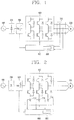
FIGS. 1 and 2 are a block diagrams schematically illustrating the configuration of a typical motor control apparatus to be applied to the present invention; -
FIGS. 3 and 4 are views illustrated for explaining a phase error generated when controlling the high-speed operation of a motor; -
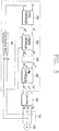
FIG. 5 is a view illustrating the detailed configuration of a motor control apparatus inFIG. 1 ; -
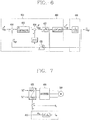
FIG. 6 is a view illustrating a mathematical model of a motor control apparatus corresponding to the present invention; -
FIG. 7 is a view illustrated for explaining the compensation operation of a phase compensation unit inFIG. 6 ; -
FIG. 8 is a graph in which the maximum operable speeds prior to and subsequent to phase compensation are compared to each other corresponding to the present invention; and -
FIG. 9 is a flow chart schematically illustrating the control method of a motor control apparatus corresponding to the present invention. - Hereinafter, a motor control apparatus and method thereof according to the present disclosure will be described in detail with reference to the accompanying drawings.
- Referring to
FIGS. 1 and 2 , a typical motor control apparatus may include aconverter 200 configured to convert an alternating-current voltage 100 to a direct-current voltage, asmoothing unit 300 configured to smooth the direct-current voltage, aninverter 400 configured to convert the smoothed direct-current voltage to apply a motor driving voltage to amotor 500, acurrent detection unit 700 configured to detect a motor driving current applied to themotor 500, and amicrocontroller 600 configured to output a control signal to theinverter 400 to drive themotor 500. - In a motor control apparatus according to the present disclosure, the microcontroller samples the motor driving current to generate the control signal, and outputs the control signal to the inverter. The motor control apparatus according to the present disclosure may further include a
phase compensation unit 800 for compensating a phase error corresponding to a delay time generated by the control signal generation time of the microcontroller. Here, the delay time means a time required from the time of receiving and sampling the motor driving current to the time of applying the motor driving voltage to the motor. - According to the present disclosure, the
current detection unit 700 is acurrent transducer 700 connected between the inverter and the motor to continuously detect the motor driving current as illustrated inFIG. 1 , or a shunt resistor connected in series to a switching element within the inverter as illustrated inFIG. 2 . The current transducer detects the motor driving current and converts it into a voltage signal to output to themicrocontroller 600. Furthermore, the current transducer detects the motor driving current during the overall interval of pulse width modulation. For example, in case of a three-phase brushless DC (BLDC) motor, thecurrent detection unit 700 detects two phases (iu, iv) of a current applied thereto in three phases to output to themicrocontroller 600. Themicrocontroller 600 generates an interrupt signal to sample a voltage signal corresponding to the detected motor driving current. - A motor control apparatus according to the present disclosure may further include an error calculation unit (not shown) for calculating a phase error due to the delay time. Taking a delay angle (phase error) corresponding to mechanical speed into consideration, it is seen that the delay angle is increased as raising the speed such as, 6° at 30 Hz, 13° at 60 Hz, 19° at 90 Hz, 26° at 120 Hz, and 32° at 150 Hz. The delay angle becomes a phase that should be compensated by using the
phase compensation unit 800. - Referring to
FIG. 5 , in a motor control apparatus according to the present disclosure, themicrocontroller 600 may include ancalculation unit 610 configured to receive the motor driving current, and calculate the speed of the motor and the position of a rotor provided in the motor, aspeed controller 620 configured to receive the reference motor speed and the calculated motor speed to output a reference current, acurrent controller 630 configured to receive the reference current and the detection current to output the reference voltage, and a pulsewidth modulation controller 640 configured to compare the triangular carrier wave with the reference voltage to generate the control signal corresponding to the comparison result. - The
calculation unit 610 receives a motor driving current detected by thecurrent detection unit 700, and calculates and estimates the speed (w) of the motor and the position of a rotor provided in the motor using a sensorless algorithm. - The
speed controller 620 may include a comparator (not shown) for comparing the user's desired reference motor speed (ω*) with the speed estimated and calculated by thecalculation unit 610, and a first proportional integral (PI) controller (not shown), and receives the reference motor speed and the calculated motor speed and proportionally integrates a difference between the reference motor speed and the calculated motor speed, namely, a speed error, to generate a q-axis reference current (i* q ), and output it to thecurrent controller 630. - The
current controller 630 receives a q-axis reference current and a d-axis reference current (i*d ) generated by thespeed controller 620 to generate and output a reference voltage. Thecurrent controller 630 allows a q-axis reference current to be passed through a second proportional integral controller and a filter and outputs a q-axis reference voltage (V*q ) to the pulsewidth modulation controller 640. In other words, thecurrent controller 630 compares the q-axis reference current with the q-axis calculated current (iq ) for which a motor driving current detected through thecurrent detection unit 700 is axially translated, and allows a difference therebetween, namely, a current error, to be passed through a second proportional integral controller and a filter and outputs a q-axis reference voltage (V* q ) to the pulsewidth modulation controller 640. On the other hand, thecurrent controller 630 allows a d-axis reference current to be passed through a third proportional integral controller and a filter and outputs a d-axis reference voltage (V*d ) to the pulsewidth modulation controller 640. In other words, thecurrent controller 630 compares the d-axis reference current with the d-axis calculated current (id ) for which a motor driving current detected through thecurrent detection unit 700 is axially translated, and allows a difference therebetween, namely, a current error, to be passed through a third proportional integral controller and a filter and outputs a d-axis reference voltage (V*d ) to the pulsewidth modulation controller 640. Here, (d, q) represents a synchronous coordinate system. - The pulse
width modulation controller 640, first, axially translates a reference voltage of the synchronous coordinate system to a reference voltage of the stationary coordinate system. In other words, the pulsewidth modulation controller 640 transforms (Ve*d, Ve*q ) into (Vs*d, Vs * d ). Here, (Vs*d , Vs*d ) may be shown as (V*α, V*β ). Furthermore, the pulsewidth modulation controller 640 converts and outputs a reference voltage of the stationary coordinate system to be matched to a motor form to be driven. For example, in case of a three-phase brushless DC (BLDC) motor, the pulsewidth modulation controller 640 converts a reference voltage of the stationary coordinate system into a reference voltage (V*a , V*b, V*c ) in three phases to output to theinverter 400. - Referring to
FIG. 5 , thephase compensation unit 800 is provided between thecurrent controller 630 and thepulse width controller 640, and added as a phase lead (Δθ e) in converting a reference voltage (Vs*d, Ve * q ) of the synchronous coordinate system outputted from thecurrent controller 630 into a reference voltage (Vs*d, Vs*d ) of the stationary coordinate system. Furthermore, thephase compensation unit 800 is a lead controller for compensating a phase lead corresponding to the speed of the motor and the sampling period of the motor driving current. As illustrated inFIG. 6 , for thecurrent controller 630 of themicrocontroller 600, its mathematical modelling may be possible in the form of combiningaxial transformation units comparator 632, a proportionalintegral controller 633, and the like. The modelling of themotor 500 may be possible with an inductance (L) and a resistance (R). Referring toFIG. 6 , a compensation angle of thephase compensation unit 800 is input to the output stage of thecurrent controller 630 in the form of ej(α Tsω e) . Furthermore, as illustrated inFIG. 7 , the compensation angle of thephase compensation unit 800 may be summed in the form of α Tsωe (=Δθe ) to be input to the axial transformation unit for transforming the synchronous coordinate system into the stationary coordinate system. Here, the a is a constant value, which is a value calculated by the error calculation unit or calculated through an experiment. Typically, the a is 1.5. -
FIG. 8 is a graph in which the maximum speeds capable of operating a motor through an experiment prior to and subsequent to phase compensation are compared to each other. Here, it is seen that the maximum operable speed subsequent to the compensation is larger than that prior to the compensation, and it is also shown that a difference between the maximum operable speeds subsequent to the compensation is more increased than that prior to the compensation as raising the frequency of a carrier wave. - Referring to
FIG. 9 , in a control method of a motor control apparatus according to the present disclosure, the motor control apparatus is provided with a converter configured to convert an alternating-current voltage to a direct-current voltage, a smoothing unit configured to smooth the direct-current voltage, and an inverter configured to convert the smoothed direct-current voltage to apply a motor driving voltage to a motor, and the method may include detecting a motor driving current applied to the motor (S100), receiving a reference motor speed (S300), calculating the reference voltage based on the motor driving current and reference motor speed (S500), generating a control signal based on the reference voltage and triangular carrier wave (not shown), compensating a phase error corresponding to a delay time generated by the control signal generation time (S600), and outputting the control signal to the inverter (S700). Here, the delay time is a time required from the start of receiving and sampling the motor driving current to the time of applying the motor driving voltage to the motor. - Said calculating the reference voltage (S500) may include calculating the speed of the motor and the position of a rotor provided in the motor (S200), calculating a reference current based on the reference motor speed and the calculated motor speed (S300), and calculates the reference voltage based on the reference current and the detection current.
- The control method may further include calculating a phase error corresponding to the delay time (S800).
- Here, said generating the control signal may include comparing the triangular carrier wave with the reference voltage, and the control signal is generated corresponding to the comparison result. Hereinafter, the configuration of the apparatus will be described with reference to
FIGS. 1 through 8 . - The motor control apparatus detects a motor driving current applied to the motor using a current detection unit (S100), and estimates and calculates the speed of the motor and the position of a rotor using the detected motor driving current (S200). Here, for the current detection unit, a current transducer connected between the inverter and the motor may be preferably used to continuously detect the motor driving current. Of course, a shunt resistor connected in series to a switching element within the inverter may be also used for the current detection unit. The current transducer detects the motor driving current and converts it into a voltage signal to output to the microcontroller, and detects the motor driving current during the overall interval of pulse width modulation. For example, in case of a three-phase brushless DC (BLDC) motor, the current detection unit detects two phases (iu, iv) of a current applied thereto in three phases to output to an calculation unit of the microcontroller, and the calculation unit estimates and calculates the speed of the motor and the position of a rotor using a sensorless algorithm therefrom (S200). The microcontroller generates an interrupt signal to sample a voltage signal corresponding to the detected motor driving current.
- The speed controller receives or calculates the user's desired reference motor speed, and receives the reference motor speed and the calculated motor speed and proportionally integrates a difference between the reference motor speed and the calculated motor speed, namely, a speed error, to calculate a q-axis reference current (S400). The current controller receives a q-axis reference current and a d-axis reference current to generate and output a reference voltage (S500). The current controller compares the q-axis reference current with the q-axis calculated current for which a motor driving current is axially translated, and allows a difference therebetween, namely, a current error, to be passed through a second proportional integral controller and a filter and calculates a q-axis reference voltage, and compares the d-axis reference current with the d-axis calculated current for which a motor driving current is axially translated, and allows a difference therebetween, namely, a current error, to be passed through a third proportional integral controller and a filter and calculates a d-axis reference voltage (S500). The pulse width modulation controller axially translates a reference voltage of the synchronous coordinate system to a reference voltage of the stationary coordinate system. Furthermore, the pulse width modulation controller converts and outputs a reference voltage of the stationary coordinate system to be matched to a motor form to be driven. For example, in case of a three-phase brushless DC (BLDC) motor, the pulse width modulation controller converts a reference voltage of the stationary coordinate system into a reference voltage in three phases to output to the inverter. The phase compensation unit is added as a phase lead in converting a reference voltage of the synchronous coordinate system to a reference voltage of the stationary coordinate system (S600). In other words, the phase compensation unit is a lead controller for compensating a phase lead corresponding to the speed of the motor and the sampling period of the motor driving current. Referring to
FIG. 6 , a compensation angle of the phase compensation unit is input to the output stage of the current controller in the form of ej(α Tsω e) . Furthermore, as illustrated inFIG. 7 , the compensation angle may be summed in the form of α Tsωe (=Δθe ) to be input to the axial transformation unit for transforming the synchronous coordinate system into the stationary coordinate system. Here, the a is a constant value, which is a value calculated by the error calculation unit or calculated through an experiment. Typically, the a is 1.5. As illustrated inFIG. 8 , when a control method of a motor control apparatus according to the present disclosure is used, it is seen that the maximum operable speed subsequent to the compensation is larger than that prior to the compensation, and it is also shown that a difference between the maximum operable speeds subsequent to the compensation is more increased than that prior to the compensation as raising the frequency of a carrier wave. - In addition, the phase compensation unit may be configured and provided with a separate hardware or firmware, and may be implemented by either one of a module form and a software algorithm within the microcontroller.
- As described above, in a motor control apparatus according to the present disclosure and a method thereof, a phase error of the reference voltage output corresponding to a time delay caused by digital control may be compensated to stably control a motor, thereby improving the stability of a system. The phase compensation unit may be provided therein to convert a reference voltage of the synchronous coordinate system into a reference voltage of the stationary coordinate system when controlling the high-speed operation of the motor, thereby compensating a phase error of the reference voltage output, and allowing the motor to be operated at a high speed while maintaining its efficiency and reducing a volume of the compressor.
Claims (13)
- A motor control apparatus, comprising:an inverter (400) configured to apply a motor driving voltage to a motor based on a control signal;a current detection unit (700) configured to detect a motor driving current applied to the motor; anda microcontroller (600) configured to sample the motor driving current, to generate the control signal based on the motor driving current, and to output the control signal to the inverter,characterized in that:
the motor control apparatus further comprises:a phase compensation unit (800) configured to compensate a phase error corresponding to a delay time of the microcontroller generating the control signal,the delay time is a time of starting the sampling to the time of applying the motor driving voltage to the motor. - The motor control apparatus of claim 1, wherein the phase compensation unit compensates the phase error corresponding to the delay time of the microcontroller generating the control signal by using a phase lead corresponding to the speed of the motor and the sampling period of the motor driving current.
- The motor control apparatus of claim 1 or 2, wherein the microcontroller comprises:an calculation unit (610) configured to calculate a speed of the motor based on the motor driving current;a speed controller (620) configured to receive a reference motor speed and the calculated motor speed and to generate a reference current based on the reference motor speed and the calculated motor speed;a current controller (630) configured to receive the reference current and a detection current and to generate a reference voltage based on the reference current and the detection current; anda pulse width modulation controller (640) configured to compare a triangular carrier wave with the reference voltage and to generate the control signal corresponding to the comparison result.
- The motor control apparatus of any of claims 1 to 3, wherein the phase compensation unit is a lead controller for compensating a phase lead corresponding to the speed of the motor and the sampling period of the motor driving current.
- The motor control apparatus of any of claims 1 to 4, wherein the phase compensation unit is provided between the current controller and the pulse width controller.
- The motor control apparatus of any of claims 1 to 5, further comprising:
an error calculation unit configured to calculate the phase error corresponding to the delay time. - The motor control apparatus of any of claims 1 to 6, wherein the current detection unit is a current transducer connected between the inverter and the motor to continuously detect the motor driving current.
- The motor control apparatus of any of claims 1 to 7, wherein the current detection unit is a shunt resistor connected in series to a switching element within the inverter.
- A control method of a motor control apparatus provided with a converter configured to convert an alternating-current voltage to a direct-current voltage, a smoothing unit configured to smooth the direct-current voltage, and an inverter configured to convert the smoothed direct-current voltage to apply a motor driving voltage to a motor, the method comprising:detecting a motor driving current applied to the motor;receiving a reference motor speed;calculating a reference voltage based on the motor driving current and the reference motor speed;generating a control signal based on the reference voltage and a triangular carrier wave;compensating a phase error corresponding to a delay time of generating the control signal; andoutputting the control signal to the inverter,wherein the delay time is a time from the time of starting the sampling to the time of applying the motor driving voltage to the motor.
- The method of claim 9, wherein said calculating the reference voltage comprises:calculating a speed of the motor based on the motor driving current;calculating a reference current based on the reference motor speed and the calculated motor speed; andcalculating the reference voltage based on the reference current and a detection current.
- The method of claim 9 or 10, wherein said generating the control signal comprises:comparing the triangular carrier wave with the reference voltage,wherein the control signal is generated corresponding to the comparison result.
- The method of any of claims 9 to 11, wherein said compensating the phase error compensates a phase lead corresponding to the speed of the motor and the sampling period of the motor driving current.
- The method of any of claims 10 to 12, further comprising:
calculating the phase error corresponding to the delay time.
Applications Claiming Priority (1)
| Application Number | Priority Date | Filing Date | Title |
|---|---|---|---|
| KR1020100037119A KR101091745B1 (en) | 2010-04-22 | 2010-04-22 | Motor controlling apparatus and controlling method of the same |
Publications (3)
| Publication Number | Publication Date |
|---|---|
| EP2387146A2 EP2387146A2 (en) | 2011-11-16 |
| EP2387146A3 EP2387146A3 (en) | 2017-11-15 |
| EP2387146B1 true EP2387146B1 (en) | 2019-12-11 |
Family
ID=44693683
Family Applications (1)
| Application Number | Title | Priority Date | Filing Date |
|---|---|---|---|
| EP11163489.5A Active EP2387146B1 (en) | 2010-04-22 | 2011-04-21 | Motor controlling apparatus and controlling method of the same |
Country Status (3)
| Country | Link |
|---|---|
| US (1) | US8766587B2 (en) |
| EP (1) | EP2387146B1 (en) |
| KR (1) | KR101091745B1 (en) |
Families Citing this family (9)
| Publication number | Priority date | Publication date | Assignee | Title |
|---|---|---|---|---|
| EP2825403B1 (en) * | 2012-03-15 | 2018-06-13 | BorgWarner Sweden AB | An electric drive axle arrangement for a road vehicle |
| CN104167974A (en) * | 2014-08-28 | 2014-11-26 | 辽宁荣信电气传动技术有限责任公司 | Encoder signal acquisition topological structure based on high-voltage inverters |
| KR102253168B1 (en) * | 2015-02-11 | 2021-05-18 | 현대모비스 주식회사 | Motor Driven Power Steering System and Method for the Vehicles |
| KR102493847B1 (en) * | 2015-10-07 | 2023-01-30 | 엘지전자 주식회사 | Motor driving apparatus and home appliance including the same |
| JP6505155B2 (en) * | 2017-04-24 | 2019-04-24 | キヤノン株式会社 | Motor control device, sheet conveying device, and image forming apparatus |
| KR101993168B1 (en) * | 2017-05-24 | 2019-09-30 | 주식회사 만도 | Apparatus For Correcting System Delay Of Motor Position Sensor And Method Of Thereof |
| KR101939467B1 (en) * | 2017-06-07 | 2019-01-16 | 엘지전자 주식회사 | Apparatus and method for driving motor |
| DE102018128354A1 (en) * | 2018-11-13 | 2020-05-14 | Beckhoff Automation Gmbh | METHOD FOR DETERMINING A ROTOR POSITION OF A BLDC MOTOR |
| CN113364381B (en) * | 2021-05-24 | 2022-03-04 | 西安理工大学 | A Segmentation Delay Compensation Strategy for Surface Mount Permanent Magnet Synchronous Motors Without Position Sensors |
Family Cites Families (11)
| Publication number | Priority date | Publication date | Assignee | Title |
|---|---|---|---|---|
| JP3259571B2 (en) * | 1995-03-14 | 2002-02-25 | 株式会社日立製作所 | PWM control device and system using the same |
| JP3346223B2 (en) * | 1997-06-10 | 2002-11-18 | 株式会社日立製作所 | Motor control method and motor control system |
| JPH11122984A (en) | 1997-10-09 | 1999-04-30 | Toyota Motor Corp | Motor control device and method |
| KR100308006B1 (en) | 1998-04-27 | 2001-11-30 | 구자홍 | compensation method of a position detecting error for BLDC motor |
| DE10037972B4 (en) * | 1999-08-05 | 2005-09-15 | Sharp K.K. | Device and method for electric motor control |
| JP2003037990A (en) | 2001-07-24 | 2003-02-07 | Hitachi Ltd | Motor control device |
| JP4269686B2 (en) * | 2003-01-09 | 2009-05-27 | 株式会社明電舎 | Sensorless measurement method and position sensorless variable speed device for synchronous motor position, speed and voltage amplitude |
| US6972534B1 (en) * | 2004-09-03 | 2005-12-06 | General Motors Corporation | Delay compensation for stable current regulation when using variable-delay random PWM switching |
| JP4765700B2 (en) * | 2005-06-01 | 2011-09-07 | 日産自動車株式会社 | Power converter |
| JP4760465B2 (en) * | 2006-03-17 | 2011-08-31 | 日産自動車株式会社 | Power converter |
| JP5133834B2 (en) * | 2008-09-30 | 2013-01-30 | トヨタ自動車株式会社 | AC motor control device |
-
2010
- 2010-04-22 KR KR1020100037119A patent/KR101091745B1/en not_active Expired - Fee Related
-
2011
- 2011-04-21 US US13/092,034 patent/US8766587B2/en not_active Expired - Fee Related
- 2011-04-21 EP EP11163489.5A patent/EP2387146B1/en active Active
Non-Patent Citations (1)
| Title |
|---|
| None * |
Also Published As
| Publication number | Publication date |
|---|---|
| US8766587B2 (en) | 2014-07-01 |
| KR20110117739A (en) | 2011-10-28 |
| KR101091745B1 (en) | 2011-12-08 |
| EP2387146A3 (en) | 2017-11-15 |
| US20110260664A1 (en) | 2011-10-27 |
| EP2387146A2 (en) | 2011-11-16 |
Similar Documents
| Publication | Publication Date | Title |
|---|---|---|
| US8766587B2 (en) | Motor controlling apparatus and controlling method of the same | |
| KR101109067B1 (en) | Position sensorless control device of permanent magnet motor | |
| EP2036195B1 (en) | Ac motor drive control device and method | |
| JP4357967B2 (en) | Control device for synchronous reluctance motor | |
| JP4057572B2 (en) | Motor rotation speed control device and speed error compensation device | |
| JP4988329B2 (en) | Beatless control device for permanent magnet motor | |
| JP2003134898A (en) | Sensorless control device and control method for synchronous generator | |
| CN115004537B (en) | Motor drive device, outdoor unit of air conditioner using the same, and motor drive control method | |
| EP3557759B1 (en) | Motor controlling apparatus and method of the same | |
| KR20150011779A (en) | motor driver | |
| JP6129972B2 (en) | AC motor control device, AC motor drive system, fluid pressure control system, positioning system | |
| JP2012120409A (en) | Motor drive device | |
| EP3116120A1 (en) | Motor system | |
| JPWO2009041157A1 (en) | Inverter control device and control method thereof | |
| JP2005229717A (en) | Current sensorless control method and apparatus for synchronous motor | |
| JP2000175483A (en) | Sensorless control method for synchronous motor and its apparatus | |
| JP5396910B2 (en) | Motor control device | |
| JP3882728B2 (en) | Electric motor control device | |
| JP5408918B2 (en) | Motor control method and control apparatus | |
| KR100857097B1 (en) | Motor control device using purge speed compensator and its method | |
| KR20080019131A (en) | Induction motor using voltage controller and its control method | |
| JP5862691B2 (en) | Control device for motor drive device and motor drive system | |
| JP5317812B2 (en) | Electric motor control device | |
| JP2010259133A (en) | Motor control device and compressor | |
| JP2022153007A (en) | Motor control device |
Legal Events
| Date | Code | Title | Description |
|---|---|---|---|
| AK | Designated contracting states |
Kind code of ref document: A2 Designated state(s): AL AT BE BG CH CY CZ DE DK EE ES FI FR GB GR HR HU IE IS IT LI LT LU LV MC MK MT NL NO PL PT RO RS SE SI SK SM TR |
|
| AX | Request for extension of the european patent |
Extension state: BA ME |
|
| PUAI | Public reference made under article 153(3) epc to a published international application that has entered the european phase |
Free format text: ORIGINAL CODE: 0009012 |
|
| PUAL | Search report despatched |
Free format text: ORIGINAL CODE: 0009013 |
|
| AK | Designated contracting states |
Kind code of ref document: A3 Designated state(s): AL AT BE BG CH CY CZ DE DK EE ES FI FR GB GR HR HU IE IS IT LI LT LU LV MC MK MT NL NO PL PT RO RS SE SI SK SM TR |
|
| AX | Request for extension of the european patent |
Extension state: BA ME |
|
| RIC1 | Information provided on ipc code assigned before grant |
Ipc: H02P 23/00 20160101AFI20171009BHEP Ipc: H02P 27/08 20060101ALI20171009BHEP |
|
| STAA | Information on the status of an ep patent application or granted ep patent |
Free format text: STATUS: REQUEST FOR EXAMINATION WAS MADE |
|
| 17P | Request for examination filed |
Effective date: 20180110 |
|
| RBV | Designated contracting states (corrected) |
Designated state(s): AL AT BE BG CH CY CZ DE DK EE ES FI FR GB GR HR HU IE IS IT LI LT LU LV MC MK MT NL NO PL PT RO RS SE SI SK SM TR |
|
| GRAP | Despatch of communication of intention to grant a patent |
Free format text: ORIGINAL CODE: EPIDOSNIGR1 |
|
| STAA | Information on the status of an ep patent application or granted ep patent |
Free format text: STATUS: GRANT OF PATENT IS INTENDED |
|
| INTG | Intention to grant announced |
Effective date: 20190626 |
|
| GRAS | Grant fee paid |
Free format text: ORIGINAL CODE: EPIDOSNIGR3 |
|
| GRAA | (expected) grant |
Free format text: ORIGINAL CODE: 0009210 |
|
| STAA | Information on the status of an ep patent application or granted ep patent |
Free format text: STATUS: THE PATENT HAS BEEN GRANTED |
|
| RAP1 | Party data changed (applicant data changed or rights of an application transferred) |
Owner name: LG ELECTRONICS INC. |
|
| AK | Designated contracting states |
Kind code of ref document: B1 Designated state(s): AL AT BE BG CH CY CZ DE DK EE ES FI FR GB GR HR HU IE IS IT LI LT LU LV MC MK MT NL NO PL PT RO RS SE SI SK SM TR |
|
| REG | Reference to a national code |
Ref country code: GB Ref legal event code: FG4D |
|
| REG | Reference to a national code |
Ref country code: CH Ref legal event code: EP |
|
| REG | Reference to a national code |
Ref country code: AT Ref legal event code: REF Ref document number: 1213187 Country of ref document: AT Kind code of ref document: T Effective date: 20191215 |
|
| REG | Reference to a national code |
Ref country code: DE Ref legal event code: R096 Ref document number: 602011063897 Country of ref document: DE |
|
| REG | Reference to a national code |
Ref country code: IE Ref legal event code: FG4D |
|
| REG | Reference to a national code |
Ref country code: NL Ref legal event code: MP Effective date: 20191211 |
|
| REG | Reference to a national code |
Ref country code: LT Ref legal event code: MG4D |
|
| PG25 | Lapsed in a contracting state [announced via postgrant information from national office to epo] |
Ref country code: LV Free format text: LAPSE BECAUSE OF FAILURE TO SUBMIT A TRANSLATION OF THE DESCRIPTION OR TO PAY THE FEE WITHIN THE PRESCRIBED TIME-LIMIT Effective date: 20191211 Ref country code: SE Free format text: LAPSE BECAUSE OF FAILURE TO SUBMIT A TRANSLATION OF THE DESCRIPTION OR TO PAY THE FEE WITHIN THE PRESCRIBED TIME-LIMIT Effective date: 20191211 Ref country code: BG Free format text: LAPSE BECAUSE OF FAILURE TO SUBMIT A TRANSLATION OF THE DESCRIPTION OR TO PAY THE FEE WITHIN THE PRESCRIBED TIME-LIMIT Effective date: 20200311 Ref country code: FI Free format text: LAPSE BECAUSE OF FAILURE TO SUBMIT A TRANSLATION OF THE DESCRIPTION OR TO PAY THE FEE WITHIN THE PRESCRIBED TIME-LIMIT Effective date: 20191211 Ref country code: NO Free format text: LAPSE BECAUSE OF FAILURE TO SUBMIT A TRANSLATION OF THE DESCRIPTION OR TO PAY THE FEE WITHIN THE PRESCRIBED TIME-LIMIT Effective date: 20200311 Ref country code: LT Free format text: LAPSE BECAUSE OF FAILURE TO SUBMIT A TRANSLATION OF THE DESCRIPTION OR TO PAY THE FEE WITHIN THE PRESCRIBED TIME-LIMIT Effective date: 20191211 Ref country code: ES Free format text: LAPSE BECAUSE OF FAILURE TO SUBMIT A TRANSLATION OF THE DESCRIPTION OR TO PAY THE FEE WITHIN THE PRESCRIBED TIME-LIMIT Effective date: 20191211 Ref country code: GR Free format text: LAPSE BECAUSE OF FAILURE TO SUBMIT A TRANSLATION OF THE DESCRIPTION OR TO PAY THE FEE WITHIN THE PRESCRIBED TIME-LIMIT Effective date: 20200312 |
|
| PG25 | Lapsed in a contracting state [announced via postgrant information from national office to epo] |
Ref country code: RS Free format text: LAPSE BECAUSE OF FAILURE TO SUBMIT A TRANSLATION OF THE DESCRIPTION OR TO PAY THE FEE WITHIN THE PRESCRIBED TIME-LIMIT Effective date: 20191211 Ref country code: HR Free format text: LAPSE BECAUSE OF FAILURE TO SUBMIT A TRANSLATION OF THE DESCRIPTION OR TO PAY THE FEE WITHIN THE PRESCRIBED TIME-LIMIT Effective date: 20191211 |
|
| PG25 | Lapsed in a contracting state [announced via postgrant information from national office to epo] |
Ref country code: AL Free format text: LAPSE BECAUSE OF FAILURE TO SUBMIT A TRANSLATION OF THE DESCRIPTION OR TO PAY THE FEE WITHIN THE PRESCRIBED TIME-LIMIT Effective date: 20191211 |
|
| PG25 | Lapsed in a contracting state [announced via postgrant information from national office to epo] |
Ref country code: CZ Free format text: LAPSE BECAUSE OF FAILURE TO SUBMIT A TRANSLATION OF THE DESCRIPTION OR TO PAY THE FEE WITHIN THE PRESCRIBED TIME-LIMIT Effective date: 20191211 Ref country code: RO Free format text: LAPSE BECAUSE OF FAILURE TO SUBMIT A TRANSLATION OF THE DESCRIPTION OR TO PAY THE FEE WITHIN THE PRESCRIBED TIME-LIMIT Effective date: 20191211 Ref country code: NL Free format text: LAPSE BECAUSE OF FAILURE TO SUBMIT A TRANSLATION OF THE DESCRIPTION OR TO PAY THE FEE WITHIN THE PRESCRIBED TIME-LIMIT Effective date: 20191211 Ref country code: EE Free format text: LAPSE BECAUSE OF FAILURE TO SUBMIT A TRANSLATION OF THE DESCRIPTION OR TO PAY THE FEE WITHIN THE PRESCRIBED TIME-LIMIT Effective date: 20191211 Ref country code: PT Free format text: LAPSE BECAUSE OF FAILURE TO SUBMIT A TRANSLATION OF THE DESCRIPTION OR TO PAY THE FEE WITHIN THE PRESCRIBED TIME-LIMIT Effective date: 20200506 |
|
| PG25 | Lapsed in a contracting state [announced via postgrant information from national office to epo] |
Ref country code: IS Free format text: LAPSE BECAUSE OF FAILURE TO SUBMIT A TRANSLATION OF THE DESCRIPTION OR TO PAY THE FEE WITHIN THE PRESCRIBED TIME-LIMIT Effective date: 20200411 Ref country code: SK Free format text: LAPSE BECAUSE OF FAILURE TO SUBMIT A TRANSLATION OF THE DESCRIPTION OR TO PAY THE FEE WITHIN THE PRESCRIBED TIME-LIMIT Effective date: 20191211 Ref country code: SM Free format text: LAPSE BECAUSE OF FAILURE TO SUBMIT A TRANSLATION OF THE DESCRIPTION OR TO PAY THE FEE WITHIN THE PRESCRIBED TIME-LIMIT Effective date: 20191211 |
|
| REG | Reference to a national code |
Ref country code: DE Ref legal event code: R097 Ref document number: 602011063897 Country of ref document: DE |
|
| REG | Reference to a national code |
Ref country code: AT Ref legal event code: MK05 Ref document number: 1213187 Country of ref document: AT Kind code of ref document: T Effective date: 20191211 |
|
| PLBE | No opposition filed within time limit |
Free format text: ORIGINAL CODE: 0009261 |
|
| STAA | Information on the status of an ep patent application or granted ep patent |
Free format text: STATUS: NO OPPOSITION FILED WITHIN TIME LIMIT |
|
| PG25 | Lapsed in a contracting state [announced via postgrant information from national office to epo] |
Ref country code: DK Free format text: LAPSE BECAUSE OF FAILURE TO SUBMIT A TRANSLATION OF THE DESCRIPTION OR TO PAY THE FEE WITHIN THE PRESCRIBED TIME-LIMIT Effective date: 20191211 |
|
| 26N | No opposition filed |
Effective date: 20200914 |
|
| PG25 | Lapsed in a contracting state [announced via postgrant information from national office to epo] |
Ref country code: SI Free format text: LAPSE BECAUSE OF FAILURE TO SUBMIT A TRANSLATION OF THE DESCRIPTION OR TO PAY THE FEE WITHIN THE PRESCRIBED TIME-LIMIT Effective date: 20191211 Ref country code: AT Free format text: LAPSE BECAUSE OF FAILURE TO SUBMIT A TRANSLATION OF THE DESCRIPTION OR TO PAY THE FEE WITHIN THE PRESCRIBED TIME-LIMIT Effective date: 20191211 Ref country code: PL Free format text: LAPSE BECAUSE OF FAILURE TO SUBMIT A TRANSLATION OF THE DESCRIPTION OR TO PAY THE FEE WITHIN THE PRESCRIBED TIME-LIMIT Effective date: 20191211 Ref country code: MC Free format text: LAPSE BECAUSE OF FAILURE TO SUBMIT A TRANSLATION OF THE DESCRIPTION OR TO PAY THE FEE WITHIN THE PRESCRIBED TIME-LIMIT Effective date: 20191211 |
|
| REG | Reference to a national code |
Ref country code: CH Ref legal event code: PL |
|
| PG25 | Lapsed in a contracting state [announced via postgrant information from national office to epo] |
Ref country code: IT Free format text: LAPSE BECAUSE OF FAILURE TO SUBMIT A TRANSLATION OF THE DESCRIPTION OR TO PAY THE FEE WITHIN THE PRESCRIBED TIME-LIMIT Effective date: 20191211 Ref country code: LU Free format text: LAPSE BECAUSE OF NON-PAYMENT OF DUE FEES Effective date: 20200421 Ref country code: FR Free format text: LAPSE BECAUSE OF NON-PAYMENT OF DUE FEES Effective date: 20200430 Ref country code: LI Free format text: LAPSE BECAUSE OF NON-PAYMENT OF DUE FEES Effective date: 20200430 Ref country code: CH Free format text: LAPSE BECAUSE OF NON-PAYMENT OF DUE FEES Effective date: 20200430 |
|
| REG | Reference to a national code |
Ref country code: BE Ref legal event code: MM Effective date: 20200430 |
|
| PG25 | Lapsed in a contracting state [announced via postgrant information from national office to epo] |
Ref country code: BE Free format text: LAPSE BECAUSE OF NON-PAYMENT OF DUE FEES Effective date: 20200430 |
|
| GBPC | Gb: european patent ceased through non-payment of renewal fee |
Effective date: 20200421 |
|
| PG25 | Lapsed in a contracting state [announced via postgrant information from national office to epo] |
Ref country code: IE Free format text: LAPSE BECAUSE OF NON-PAYMENT OF DUE FEES Effective date: 20200421 Ref country code: GB Free format text: LAPSE BECAUSE OF NON-PAYMENT OF DUE FEES Effective date: 20200421 |
|
| PG25 | Lapsed in a contracting state [announced via postgrant information from national office to epo] |
Ref country code: TR Free format text: LAPSE BECAUSE OF FAILURE TO SUBMIT A TRANSLATION OF THE DESCRIPTION OR TO PAY THE FEE WITHIN THE PRESCRIBED TIME-LIMIT Effective date: 20191211 Ref country code: MT Free format text: LAPSE BECAUSE OF FAILURE TO SUBMIT A TRANSLATION OF THE DESCRIPTION OR TO PAY THE FEE WITHIN THE PRESCRIBED TIME-LIMIT Effective date: 20191211 Ref country code: CY Free format text: LAPSE BECAUSE OF FAILURE TO SUBMIT A TRANSLATION OF THE DESCRIPTION OR TO PAY THE FEE WITHIN THE PRESCRIBED TIME-LIMIT Effective date: 20191211 |
|
| PG25 | Lapsed in a contracting state [announced via postgrant information from national office to epo] |
Ref country code: MK Free format text: LAPSE BECAUSE OF FAILURE TO SUBMIT A TRANSLATION OF THE DESCRIPTION OR TO PAY THE FEE WITHIN THE PRESCRIBED TIME-LIMIT Effective date: 20191211 |
|
| PGFP | Annual fee paid to national office [announced via postgrant information from national office to epo] |
Ref country code: DE Payment date: 20220308 Year of fee payment: 12 |
|
| REG | Reference to a national code |
Ref country code: DE Ref legal event code: R119 Ref document number: 602011063897 Country of ref document: DE |
|
| PG25 | Lapsed in a contracting state [announced via postgrant information from national office to epo] |
Ref country code: DE Free format text: LAPSE BECAUSE OF NON-PAYMENT OF DUE FEES Effective date: 20231103 |