EP2386255A2 - Endoscope treatment instrument - Google Patents
Endoscope treatment instrument Download PDFInfo
- Publication number
- EP2386255A2 EP2386255A2 EP11006136A EP11006136A EP2386255A2 EP 2386255 A2 EP2386255 A2 EP 2386255A2 EP 11006136 A EP11006136 A EP 11006136A EP 11006136 A EP11006136 A EP 11006136A EP 2386255 A2 EP2386255 A2 EP 2386255A2
- Authority
- EP
- European Patent Office
- Prior art keywords
- coil
- actuator
- endoscope
- ratchet
- transmitting member
- Prior art date
- Legal status (The legal status is an assumption and is not a legal conclusion. Google has not performed a legal analysis and makes no representation as to the accuracy of the status listed.)
- Granted
Links
- 230000009471 action Effects 0.000 claims abstract description 6
- 210000000078 claw Anatomy 0.000 claims description 28
- 230000007246 mechanism Effects 0.000 claims description 12
- 238000005452 bending Methods 0.000 abstract description 19
- 239000010410 layer Substances 0.000 description 47
- 238000002224 dissection Methods 0.000 description 32
- 230000002262 irrigation Effects 0.000 description 13
- 238000003973 irrigation Methods 0.000 description 13
- 230000004048 modification Effects 0.000 description 9
- 238000012986 modification Methods 0.000 description 9
- 238000013461 design Methods 0.000 description 7
- 238000005476 soldering Methods 0.000 description 6
- 230000000694 effects Effects 0.000 description 5
- 238000000034 method Methods 0.000 description 5
- 239000002184 metal Substances 0.000 description 4
- 239000012530 fluid Substances 0.000 description 3
- 230000001105 regulatory effect Effects 0.000 description 3
- 239000002356 single layer Substances 0.000 description 3
- 208000032843 Hemorrhage Diseases 0.000 description 2
- 238000001574 biopsy Methods 0.000 description 2
- 238000004891 communication Methods 0.000 description 2
- 238000003780 insertion Methods 0.000 description 2
- 230000037431 insertion Effects 0.000 description 2
- 230000002093 peripheral effect Effects 0.000 description 2
- 238000003466 welding Methods 0.000 description 2
- 238000004804 winding Methods 0.000 description 2
- 238000007792 addition Methods 0.000 description 1
- 230000008859 change Effects 0.000 description 1
- 230000005611 electricity Effects 0.000 description 1
- 230000007794 irritation Effects 0.000 description 1
- 239000000463 material Substances 0.000 description 1
- 230000000149 penetrating effect Effects 0.000 description 1
- 230000002787 reinforcement Effects 0.000 description 1
- 230000004044 response Effects 0.000 description 1
- 238000006467 substitution reaction Methods 0.000 description 1
- XLYOFNOQVPJJNP-UHFFFAOYSA-N water Substances O XLYOFNOQVPJJNP-UHFFFAOYSA-N 0.000 description 1
Images


Classifications
-
- A—HUMAN NECESSITIES
- A61—MEDICAL OR VETERINARY SCIENCE; HYGIENE
- A61B—DIAGNOSIS; SURGERY; IDENTIFICATION
- A61B17/00—Surgical instruments, devices or methods, e.g. tourniquets
- A61B17/28—Surgical forceps
- A61B17/29—Forceps for use in minimally invasive surgery
-
- A—HUMAN NECESSITIES
- A61—MEDICAL OR VETERINARY SCIENCE; HYGIENE
- A61B—DIAGNOSIS; SURGERY; IDENTIFICATION
- A61B18/00—Surgical instruments, devices or methods for transferring non-mechanical forms of energy to or from the body
- A61B18/04—Surgical instruments, devices or methods for transferring non-mechanical forms of energy to or from the body by heating
- A61B18/12—Surgical instruments, devices or methods for transferring non-mechanical forms of energy to or from the body by heating by passing a current through the tissue to be heated, e.g. high-frequency current
- A61B18/14—Probes or electrodes therefor
- A61B18/1492—Probes or electrodes therefor having a flexible, catheter-like structure, e.g. for heart ablation
-
- A—HUMAN NECESSITIES
- A61—MEDICAL OR VETERINARY SCIENCE; HYGIENE
- A61B—DIAGNOSIS; SURGERY; IDENTIFICATION
- A61B17/00—Surgical instruments, devices or methods, e.g. tourniquets
- A61B17/28—Surgical forceps
- A61B17/29—Forceps for use in minimally invasive surgery
- A61B2017/2901—Details of shaft
- A61B2017/2905—Details of shaft flexible
-
- A—HUMAN NECESSITIES
- A61—MEDICAL OR VETERINARY SCIENCE; HYGIENE
- A61B—DIAGNOSIS; SURGERY; IDENTIFICATION
- A61B17/00—Surgical instruments, devices or methods, e.g. tourniquets
- A61B17/28—Surgical forceps
- A61B17/29—Forceps for use in minimally invasive surgery
- A61B2017/2901—Details of shaft
- A61B2017/2906—Multiple forceps
-
- A—HUMAN NECESSITIES
- A61—MEDICAL OR VETERINARY SCIENCE; HYGIENE
- A61B—DIAGNOSIS; SURGERY; IDENTIFICATION
- A61B17/00—Surgical instruments, devices or methods, e.g. tourniquets
- A61B17/28—Surgical forceps
- A61B17/29—Forceps for use in minimally invasive surgery
- A61B17/2909—Handles
- A61B2017/291—Handles the position of the handle being adjustable with respect to the shaft
-
- A—HUMAN NECESSITIES
- A61—MEDICAL OR VETERINARY SCIENCE; HYGIENE
- A61B—DIAGNOSIS; SURGERY; IDENTIFICATION
- A61B17/00—Surgical instruments, devices or methods, e.g. tourniquets
- A61B17/28—Surgical forceps
- A61B17/29—Forceps for use in minimally invasive surgery
- A61B2017/2926—Details of heads or jaws
- A61B2017/2927—Details of heads or jaws the angular position of the head being adjustable with respect to the shaft
- A61B2017/2929—Details of heads or jaws the angular position of the head being adjustable with respect to the shaft with a head rotatable about the longitudinal axis of the shaft
-
- A—HUMAN NECESSITIES
- A61—MEDICAL OR VETERINARY SCIENCE; HYGIENE
- A61B—DIAGNOSIS; SURGERY; IDENTIFICATION
- A61B18/00—Surgical instruments, devices or methods for transferring non-mechanical forms of energy to or from the body
- A61B2018/0091—Handpieces of the surgical instrument or device
- A61B2018/00916—Handpieces of the surgical instrument or device with means for switching or controlling the main function of the instrument or device
-
- A—HUMAN NECESSITIES
- A61—MEDICAL OR VETERINARY SCIENCE; HYGIENE
- A61B—DIAGNOSIS; SURGERY; IDENTIFICATION
- A61B18/00—Surgical instruments, devices or methods for transferring non-mechanical forms of energy to or from the body
- A61B18/04—Surgical instruments, devices or methods for transferring non-mechanical forms of energy to or from the body by heating
- A61B18/12—Surgical instruments, devices or methods for transferring non-mechanical forms of energy to or from the body by heating by passing a current through the tissue to be heated, e.g. high-frequency current
- A61B18/14—Probes or electrodes therefor
- A61B2018/1405—Electrodes having a specific shape
- A61B2018/1422—Hook
-
- A—HUMAN NECESSITIES
- A61—MEDICAL OR VETERINARY SCIENCE; HYGIENE
- A61B—DIAGNOSIS; SURGERY; IDENTIFICATION
- A61B18/00—Surgical instruments, devices or methods for transferring non-mechanical forms of energy to or from the body
- A61B18/04—Surgical instruments, devices or methods for transferring non-mechanical forms of energy to or from the body by heating
- A61B18/12—Surgical instruments, devices or methods for transferring non-mechanical forms of energy to or from the body by heating by passing a current through the tissue to be heated, e.g. high-frequency current
- A61B18/14—Probes or electrodes therefor
- A61B2018/1475—Electrodes retractable in or deployable from a housing
Definitions
- the present invention relates to an endoscope treatment instrument that is a treatment instrument employed in combination with a flexible endoscope for example, this endoscope treatment instrument being provided with a sheath that has both the property of rotational follow-up as well as the characteristics required of a sheath equipped with a treatment portion.
- Endoscope treatment instruments that are employed by insertion into the channel of a flexible endoscope conventionally include such examples as dissection instruments, grasping forceps, etc.
- various treatment portions such as a forceps cap or jaws, or an electrode etc., composing a dissection part, are formed at the distal end of a flexible sheath.
- the proximal end of the sheath is rotated and this rotational force is transmitted via the sheath to the treatment portion at the distal end, thereby rotating the treatment portion.
- the entire length of an operating wire is inserted into a flexible sheath that is inserted into a channel.
- a forceps cap which can be opened and closed is provided to the distal end of the operating wire, and an actuator is provided at the proximal end side.
- the sheath is formed of a multiple layer coil in which two coil pipes are stacked on top of one another, and wound in opposite directions.
- the proximal end of the sheath is fixed in place to the actuator.
- the device disclosed in Japanese Patent Application, First Publication No. Hei 3-47246 is provided with a sheath consisting of a flexible, tightly wound coil, a treatment portion such as a biopsy cap provided at the distal end of the sheath, and an actuator which is provided on the handheld side of the sheath.
- the movement of the actuator is communicated to the treatment portion via an operating wire which is inserted into the sheath.
- the sheath is provided with three types of tightly wound coils: a single strand apex coil, a single strand intermediate coil that has a thicker diameter than the apex coil, and a multiple strand rear end coil.
- the hardness of the coils gradually increases from the apex to the rear.
- the biopsy cap or other such treatment portion can be opened or closed.
- the sheath rotates when the actuator for the treatment instrument is rotated, thereby enabling the orientation to be changed.
- the actuator and the proximal end of the sheath are rotated, and this rotational force is communicated to the treatment portion via the sheath, thereby adjusting its orientation.
- the distal end part (within the range of 200 mm from the proximal end of the treatment portion, for example) which overlaps the bending part of the endoscope, be flexible.
- the endoscope treatment instrument according to the present invention is provided with a flexible transmitting member, a treatment portion that is attached to the distal end of the transmitting member, and an actuator which is attached to the proximal end of the transmitting member and is for operating the treatment portion, this endoscope treatment instrument being designed to transmit the action of the actuator to the treatment portion via the transmitting member.
- the endoscope treatment instrument according to the present invention is characterized in that the transmitting member consists of the connection in the longitudinal direction of a first coil sheath that has excellent rotation follow-up and good relative bending properties, and a second coil sheath that has excellent rotation follow-up and good ease of motion in the relative longitudinal direction.
- first coil sheath be connected on the treatment portion side, and the second coil sheath be connected on the proximal end side of the first coil sheath, in the transmitting member of the endoscope treatment instrument according to the present invention.
- respective first coil sheath be connected to the treatment portion side and the actuator side, and that a second coil sheath be connected between these first coil sheath.
- the first coil sheath be formed of a multiple layer coil and the second coil sheath be formed of a multiple strand coil. Further, it is preferable that the multiple layer coil be formed of a single strand coil or a multiple strand coil, and the multiple strand coil be a single layer coil.
- the endoscope treatment instrument is provided with a flexible transmitting member, a treatment portion that is attached to the distal end of the transmitting member, and an actuator which is attached to the proximal end of the transmitting member and is for operating the treatment portion, this endoscope treatment instrument being designed to transmit the action of the actuator to the treatment portion via the transmitting member, and being characterized in that the treatment portion is a high-frequency treatment instrument, and in that the actuator is provided with a sliding body that is electrically connected to the high-frequency treatment instrument via the transmitting member, a support that is electrically connected to a connector, and a ratchet mechanism that is provided to enable electrical conduction or interruption between the sliding body and the support.
- the ratchet mechanism may be provided with ratchet teeth that are provided to one of either the sliding body and the support, and a ratchet claw that is provided to the other of the sliding body and the support, and which can engage with the ratchet teeth.
- the sliding body is connected to the transmitting member, and the treatment portion can be advanced and/or retracted via the transmitting member, by advancing and/or retracting the sliding body when the ratchet teeth and the ratchet claw are in a state of engagement.
- the operating member that is provided with one of either the ratchet claw and ratchet teeth be provided to the sliding body in a manner which permits advancing and retracting, and that the operating member be biased by an elastic member in a direction so as to cause engagement between the ratchet claw and the ratchet teeth and permit electrical conduction, and that the electrical current be interrupted by separating the ratchet claw and the ratchet teeth by moving the operating member in the direction that is opposite the biasing force of the elastic member.
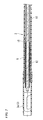
- FIGS. 1 and 2 show a soft dissection instrument 1 which is the endoscope treatment instrument according to the first embodiment.
- This dissection instrument 1 is provided with a flexible inserted part 2, a treatment portion 3 attached to the distal end of the inserted part 2, and an actuator 4 connected to the proximal end of the inserted part 2.
- the inserted part 2 has a flexible shaft, such as a coil sheath, that is inserted inside a tube 6, and can be advanced into a body cavity by insertion into the instrument channel of the endoscope.
- the treatment portion 3 is a dissection portion, provided with, for example, a high-frequency hook 3a which serves as a hook consisting of an electrode.
- the actuator 4 which is provided to the proximal end of the inserted part 2 is provided with a main body 7 extending in the longitudinal direction of the inserted part 2, and a slider 8 which can slide with respect to the main body 7.
- a connecting part 10 which can be connected to a high-frequency power source is provided to the slider 8, and is electrically conductive with the high-frequency hook 3a via the shaft.
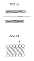
- a multiple layer coil, three-layer coil 12 for example, having conductivity is disposed to the proximal end of the high-frequency hook 3a as the distal shaft.
- the three-layer coil 12 is formed by winding three layers of metal wire in the radial direction such as shown in the expanded view in FIG. 3A , and extends to a length of approximately 200 mm, for example.
- Multiple layer coils, including three-layer coil 12 have excellent rotation follow-up and are softer and have better bending properties as compared to multiple strand coils.
- the three-layer coil 12 can form a curved part that can bend or curve in order to incise, etc. the diseased area using the high-frequency hook 3a.
- a conductive single layer, multiple strand coil, nine-strand coil 13 for example, is connected to the proximal end side of the three-layer coil 12 and serves as a long shaft, the length of which is greater than that of the three-layer coil 12.
- the nine-strand coil 13 is formed by aligning and winding a plurality (nine here) of metal wires as shown in FIG. 3B .
- multiple strand coils, including the nine-strand coil 13 has excellent rotation follow-up as compared to a single strand coil, and has the property of greater rigidity as compared to multiple layer coils, including the three-layer coil 12.
- Multiple strand coils are also very easily moved to advance or retract.
- the slider 8 is connected to the proximal end of the nine-strand coil 13 by soldering or other such methods. Note that a shaft is formed by the connection of the three-layer coil 12 and the multiple strand coil 13.
- the hook 3a can be projected out from the tube 6 via the nine-strand coil 13 and the three-layer coil 12 (see FIG. 4 ) by advancing the slider 8 along the main body 7 (i.e., moving slider 8 toward the hook 3a side) in the actuator 4, and can be housed within the tube 6 by retracting the slider 8 along the main body 7 (see FIG. 2 ) in the actuator 4. Further, by rotating the actuator 4, the hook 3a can be rotated by a specific angle via the nine-strand coil 13 and the three-layer coil 12.
- the connecting part between the three-layer coil 12 and the nine-strand coil 13 may be formed as follows, for example.
- the outer peripheral surfaces near the connection between the three-layer coil 12 and the nine-strand coil 13 are cut out to provide step portions to the outer diameters.
- the respective step portions of the three-layer coil 12 and the nine-strand coil 13 are inserted into a cylindrical connecting tube 15 which has the same outer diameter as the three-layer coil 12 and the nine-strand coil 13, and engage therewithin.
- Soldering material is injected into the boundary area between the three-layer coil 12 and the nine-strand coil 13 via a through hole (not shown in the figures) that passes through the connecting tube 15.
- the inner surface of the connecting tube 15, and the boundary area between the three-layer coil 12 and the nine-strand coil 13, are thus connected by soldering.
- the three-layer coil 12 and nine-strand coil 13, and the connecting tube 15, have roughly the same outer diameter along the entire length.
- the dissection instrument 1 according to this embodiment is provided with the above-described design. The effects thereof will now be described.
- the inserted part 2 and the treatment portion 3a of the dissection instrument 1 are inserted into a body cavity via the instrument channel of an endoscope, which is not shown in the figures.
- the dissection instrument 1 is projected out from the distal end of the endoscope, after which the high-frequency hook 3a is made to project out from the tube 6 by advancing or retracting the slider 8 of the actuator 4 with respect to the main body 7 (see FIG. 4 ).
- the inserted part 2 with the exception of its distal end part, is formed of the long nine-strand coil 13, it can be projected forward easily.
- the three-layer coil 12 on the distal end side is short in length, so that it has only a slight effect on ease of use.
- the tissue is then incised by bringing the high-frequency hook 3a, through which current is flowing, into contact with the target tissue inside the body cavity.
- the actuator 4 may be rotated in the case where the high-frequency hook 3a does not have the desired orientation with respect to the tissue.
- the rotational force from rotating actuator 4 is communicated via the nine-strand coil 13 and the three-layer coil 12 inside the tube 6, causing the high-frequency hook 3a to rotate and be positioned with the desired orientation.
- the distal end part of the inserted part 2 bends, it is formed of the highly flexible three-layer coil 12 so that it does not have an effect on the bending posture of the endoscope, and the rotation of the long nine-strand coil 13 can be communicated to the high-frequency hook 3a with certainty.
- the rotation follow-up over the entire length of the inserted part 2 is excellent, and advancing and retracting can be carried out easily using the long nine-strand coil 13.
- the distal end part of the inserted part 2 is a three-layer coil 12 so that the bending of the distal end part of the endoscope can be carried out smoothly. Further, communication of the rotation to the high-frequency hook 3a when in the bent state can be carried out with certainty.
- a medical treatment endoscope 20 is provided with an endoscope inserted part 28, the proximal end side thereof being attached to a base via a branch connection 22c.
- a first sheath 22 and a second sheath 27 extend branching from the proximal end side of the branch connection 22c.
- An actuator 21 of the medical treatment endoscope is provided to the proximal end of the first sheath 22. As shown in FIG.
- an actuator 65 for operating the jaws 26a of the gripping forceps 26, and an actuator 24 for operating the high-frequency hook 3a of the dissection instrument 23 are disposed in alignment at a specific angle in this actuator 21 of the medical treatment endoscope.
- These actuators 65, 24 are designed to be operated by gripping with the left and right hands respectively.
- a plurality of individual channels are provided in the space extending from the actuator 21 of the medical treatment endoscope to the first sheath 22 and the opening at the distal end of the endoscope inserted part 28.
- the inserted part 25 of the dissection instrument 23 according to the second embodiment of the present invention and the inserted part (not shown) of the gripping forceps 26 are inserted respectively into these channels.
- a separate channel is provided within the second sheath 27 and the endoscope inserted part 28.
- An irrigation and suction tube 30 is inserted into this separate channel via a stopper 29 that is provided in the proximal end side of the second sheath 27, and projects out from the opening at the distal end.
- An irrigation and suction device 31, for example, for performing irrigation and suction, is provided at the proximal end of the irrigation and suction tube 30.
- an arm 25a and an arm 26b are provided at the distal end of the endoscope inserted part 28.
- the high-frequency hook 3a of the dissection instrument 23 and the jaws 26a of the gripping forceps 26 project out respectively from the distal end of each of the arms 25a, 26b.
- the irrigation and suction tube 30 projects out from the opening of the separate channel at the distal end of the endoscope inserted part 28.
- a main opening 30a is provided at the distal end and one or more side openings 30b are provided to the sides of the irritation and suction tube 30.
- the irrigation and suction tube 30 can provide irrigation to wash away hemorrhage at the diseased area K inside the body cavity, expelling fluid from the main and side openings 30a,30b, or can suction and recover water, etc. that has accumulated at the diseased area K.
- a proximal end side bending part 22a is formed to the first sheath 22, and a distal end side bending part 28a is formed to the endoscope inserted part 28 at its distal opening side.
- the presence or absence of the respective bending parts 22a,28a of the first sheath 22 and the endoscope bending part 28 depends on the position of attachment and the method of use, and it is not absolutely essential that the parts be bent.
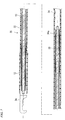
- FIG. 6 shows an overall view of the dissection instrument 23 which is inserted into the endoscope inserted part 28 and the first sheath 22 as explained above.
- the tube 32 of the inserted part 25 is provided to the distal end side of the actuator 24, and a high-frequency hook 3a is provided in a manner to permit advancing and retracting from the opening at the distal end of the tube 32.
- a relatively flexible multiple layer coil, three-layer coil 12 for example, having good rotation follow-up, is connected by welding, etc. to the proximal end of the high-frequency hook 3a, and serves as a distal shaft.
- a relatively rigid multiple strand coil, nine-strand coil 13 for example, having good rotation follow-up, is connected to the proximal end of the three-layer coil 12, and serves as an intermediate shaft.
- the nine-strand coil 13 is long, and its connection with the three-layer coil 12 is fixed by soldering, etc. at the step portions via the connecting tube 15 as explained above.
- the connection between the nine-strand coil 13 and the three-layer coil 33, i.e., the proximal shaft, has the same structure as the connection between the nine-strand coil 13 and the three-layer coil 12, i.e., the distal shaft, and is connected by soldering when the connecting tube 15 is in a state of engagement with the step portions of the nine-strand coil 13 and the three-layer coil 33.
- the mutually connected three-layer coil 12, nine-strand coil 13 and three-layer coil 33 are together referred to as a "shaft".
- the respective three-layer coils 12, 33 on the distal and proximal end sides are positioned at the distal end side bending part 28a of the endoscope inserted part 28 and the proximal end side bending part 22a of the first sheath 22 in the medical treatment endoscope 20.
- the proximal end of the three-layer coil 33 on the proximal end side engages with the inside of a concavity 34a in an operating shaft 34, and is connected there by welding or soldering.
- This operating shaft 34 is rigid and extends inside the actuator 24 and is connected to the actuator 24 as described below.
- the actuator 24 is provided with a main body 37 that is roughly tubular.
- the base of the tube 32 passes through a tubular part 36.
- the base of the tubular part 36 is provided at the distal end of the main body 37, and is attached to the inside of a cylindrical member 38 which is supported by the inside of the main body 37 to permit relative rotation.
- a flange 38a that projects radially from the distal end of the main body 37 is formed to the distal end of the cylindrical member 38.
- the main body 37 of the actuator 24 is designed to enable rotation with respect to the cylindrical member 38 via axes 39 which are provided at the base of the cylindrical member 38.
- a guide groove 40 is formed at a central area along the longitudinal direction of the main body 37, and extends longitudinally to a flat central upper surface 37a (see FIG. 9A, FIG. 9B ).
- a fixing part 41 is disposed to enable sliding within the main body 37 within the limits of the guide groove 40.
- the fixing part 41 fixes the operating shaft 34 which passes through the cylindrical member 38 and extends to the proximal end side.
- the center axis O of the operating shift 34 preferably coincides with the center axis O' of the main body 37.
- the fixing part 41 shown in FIG. 8 and FIG. 10A has a first sliding part 43 that can slide inside the main body 37 and is provided with an internal through hole 42 that is formed in the direction of sliding.
- a fixing concavity 45 is formed to the first sliding part 43, perpendicular to the through hole 42.
- a fixed axis 44 which extends outward along the guide groove 40 of the main body 37 can be inserted to permit reciprocating motion (vertical motion) within the fixing concavity 45.
- An actuator button 44a is provided to the head on the fixed axis 44, and a stepped part 44b is formed in the bottom part of the fixed axis 44.
- a coil spring 47 for example, is attached as an elastic member between the stepped part 44b and the bottom part of the fixing concavity 45.
- the fixed axis 44 is biased so as to project out from the guide groove 40.
- a long hole 46 is formed in the fixed axis 44, and a regulating pin 49 which is provided to the first sliding part 43 is inserted into this long hole 46.
- the extent of the reciprocating motion (vertical motion) of the fixed axis 44 is regulated by this long hole 46 and regulating pin 49.
- a roughly gourd-shaped fixing hole 48 in which a large diameter part 48a and a slit 48b communicate when positioned on top of through hole 42, is formed in the approximate center of the fixed axis 44.
- the base 34b of the operating shaft 34 is inserted into the fixing hole 48.
- This base 34b is formed to be roughly oval in cross-section to permit engagement with the slit 48b of the fixing hole 48, as shown in FIG. 10B .
- the base 34b of the operating shaft 34 is engaged and fixed in place in the slit 48b of the fixing hole 48 due to the biasing force of the coil spring 47.
- the operating shaft 34 is designed to permit unitary rotation together with the main body 37 around the center axis O of the operating shaft 34. As a result, it is possible to change the angle of the high-frequency hook 3a with respect to the diseased area K by rotating the main body 37.
- the operating button 44a of the fixed axis 44 by pushing the operating button 44a of the fixed axis 44, the fixed axis 44 is moved toward the bottom of the fixing concavity 45 against the biasing force of the coil spring 47, so that the base 34b of the operating shaft 34 is moved from the slit 48b into the large diameter part 48a.
- the operating shaft 34 is thereby released from the main body 37.
- an operating member 50 is provided adjacent to the fixing part 41.
- a roughly cylindrical second sliding part 51 to which the first sliding part 43 of the fixing part 41 is connected by a screw or the like is provided in the operating member 50. Together these form a unitary sliding member.
- These first and second sliding members 43, 51 can be moved by sliding in a unitary manner within the main body 37.
- a through hole 51a is formed in the longitudinal direction within the second sliding part 51.
- a ratchet member 53 provided with ratchet teeth 52 is disposed in a fixed manner inside the through hole 51a as a support.
- the base 53a of the ratchet member 53 engages in a concavity at the proximal end portion 37b of the main body 37.
- a connector 54 which is exposed at the proximal end surface 37c of the main body 37 is attached to the rear of the base 53a of the ratchet member 53.
- a knob 56 which projects outward passing through the guide groove 40 is provided to the second sliding part 51.
- An operating hole 57 is formed extending in the direction in which the knob 56 and the second sliding part 51 are perpendicular to the center axis O', and communicates with a through hole 51a.
- the operating axis 58 is inserted from the knob 56 into the operating hole 57 so as to permit reciprocating motion (vertical motion) within specific limits.
- the operating axis 58 is provided with an operating button 58a at its head, and a stepped part 58b at its bottom.
- the center portion widens to a roughly square shape when seen in vertical cross-section, and a window 58c is formed penetrating internally.
- a coil spring 60 is attached in a compressed state in between the stepped part 58b that is provided to the bottom of the operating axis 58 and the step 57a that is provided at the bottom of the operating hole 57, coil spring 60 serving as an elastic member.
- the ratchet teeth 52 of the ratchet member 53 and the ratchet claw 61 that is provided to the window 58c form a ratchet mechanism in which they engage with one another when the operating axis 58 is pushed upward under the biasing force of the coil spring 60 (see FIG. 12 ).
- the tooth profile of the ratchet teeth 52 is formed so that when engaged with the ratchet claw 61, for example, the second sliding part 51 which includes the ratchet claw 61 can move in one direction, forward for example, but movement in the opposite direction toward the proximal end is prohibited.
- the ratchet member 53 attached to the connector 54, the operating axis 58, the coil spring 60, the second sliding part 51, the first sliding part 43 of the fixing part 41, the coil spring 47, and the fixed axis 44 are formed of a conductive member, and can transmit electricity to the high-frequency hook 3a via the operating shaft 34 and the shafts (various coils 12, 13, 33) which consist of the same conductive member. Further, by pushing the operating button 58a in the operating member 50, the ratchet claw 61 of the operating axis 58 can be moved away from the ratchet teeth 52, thus interrupting current flow between them.
- a space 63 is formed between the cylindrical member 38 and the ratchet member 53 inside the main body 37 of the actuator 24, and is designed to permit the first sliding part 43 of the fixing part 41 and the second sliding part 51 of the operating member 50 to slide in unison.
- the knob 56 can move forward along the guide groove 40.
- the first sliding part 43 and the second sliding part 51 move through internal space 63 inside the main body 37 in a unitary manner, causing the high-frequency hook 3a to move forward via the fixing part 41.
- the hook 3a By moving the knob 56 forward with the ratchet claw 61 in a state of engagement with the ratchet teeth 52, the hook 3a can be made to project out in a state of conduction.
- the first and second sliding parts 43,51 rotate in unison, rotating from the operating shaft 34 to the hook 3a about the same axis.
- FIG. 16 shows an example of a modification of the above-described ratchet mechanism.
- the ratchet teeth 52A and the ratchet claw 61A shown in FIG. 16 form a peaked tooth profile that permits movement of the second sliding part 51 in the advancing or retracting direction when engaged.
- the high-frequency hook 3a can be advanced or retracted with respect to the tube 32 without pushing an operating button 58a, by moving the knob 56 forward or back when the ratchet teeth 52A and the ratchet claw 61A are engaged, i.e., when maintaining a state of conduction.
- the medical treatment endoscope 20 equipped with a dissection instrument 23 according to the second embodiment is provided with the above-described design. The effects thereof will now be described.
- the endoscope inserted part 28 of the medical treatment endoscope 20 is inserted into a body cavity as shown in FIG. 5 .
- Dissection instrument 23 and gripping forceps 26, for example, are then inserted as treatment instruments via respective channels of the endoscope inserted part 28, and the front ends thereof are made to project out from the arms 25a, 26b.
- a technician While moving the distal arms 25a, 26b by manipulating the actuator 21 of the medical treatment endoscope, a technician, for example, carries out the procedure on the diseased area K by using his left hand to manipulate the actuator 65 of the gripping forceps 26 and using his right hand to manipulate the actuator 24 of the dissection instrument 23.
- the diseased area K is gripped in the jaws 26a of the gripping forceps 26.
- the dissection instrument 23 is moved forward (toward the high-frequency hook 3a side) by moving the knob 56 of the actuator 24 along the guide groove 40.
- the knob 56 of the actuator 24 moves along the guide groove 40.
- the ratchet teeth 52 and the ratchet claw 61 in a state of engagement, the second sliding part 51 and the first sliding part 43 of the fixing part 41, together with the ratchet claw 61, are moved forward through the internal space 63 of the main body 37, and the operating shaft 34, which is fixedly attached to the fixing part 41, moves forward.
- the high-frequency hook 3a is advanced and projected out from the distal opening of the tube 32 via the three-layer coil 33, the nine-strand coil 13, and the three-layer coil 12 inside the tube 32.
- the long nine-strand coil 13 is highly rigid, so that it can be advanced and retracted easily.
- the main body 37 of the actuator 24 is rotated by the desired angle with respect to the cylindrical member 38 around the center axis O'.
- the operating shaft 34 is fixed to a fixing part 41 which rotates in unison with the main body 37, the operating shaft 34 is also rotated around the center axis O.
- the highly flexible respective three layer coils 33, 12 are positioned at bending parts 22a,28a, so that the orientation of the high-frequency hook 3a can be adjusted to the specific angle through the communication of the rotation via the respective coils 33,13,12 which have excellent rotation follow-up.
- a power source cord which is not shown in the figures, is attached to the connector 54 of the actuator 24.
- a high-frequency current can be communicated with certainty to the high-frequency hook 3a at the distal end from the connecting part at the rear end, via the ratchet member 53, the ratchet teeth 52 and ratchet claw 61 which are in a state of engagement, the second sliding part 51, the first sliding part 43, the operating shaft 34, the shafts (various coils 33, 13, 12), and the like.
- the diseased area K gripped by the jaws 26a of the gripping forceps 26 can be incised using the high-frequency hook 3a.
- the knob 56 may be retracted along the guide groove 40 while pushing the operating button 58a of the actuator 24. Further, in the ratchet mechanism according to the modified example shown in FIG. 16 , it is not necessary to push the operating button 58a when pulling in the hook 3a.
- the irrigation and suction tube 30 consisting of a flexible tube may be inserted via the second sheath 27, and passed though the endoscope inserted part 28, so that the main opening 30a at its distal end is projected into the vicinity of the diseased area K. Further, when there is hemorrhage or the like around the diseased area K, irrigating fluid may be expelled from the irrigation and suction device 31 to wash the area, and fluid remaining inside the body may be suctioned out.
- side openings 30b are formed near the main opening 30a at the distal end of the irrigation and suction tube 30, so that irrigation and suction can still be carried out via these side openings 30b even if the main opening 30a at the distal end is blocked by coming into contact with the body wall. Note that there is no connecting component at the distal end of the irrigation and suction tube 30, thus there is no concern about such components falling off.
- the distal end of the tube 68 extends further forward than the distal end of the three-layer coil 12 which serves as the distal shaft, and there is formed an opening 68b, the diameter of which is widened by means of a small diameter part 68a which has been formed with a small diameter.
- a rigid rod-shaped electrode extension 69 which connects the three-layer coil 12 and the high-frequency hook 3a is disposed inside the small diameter part 68a.
- the electrode extension 69 forms an electrical single wire, having a length of 100 mm, for example.
- a first stopper 71 for preventing the connecting part 70 between the electrode extension 69 and the three-layer coil 12 from projecting forward is provided to the inner peripheral surface of the tube 68.
- the tube 68 is positioned on the proximal end side of the small diameter part 68a, and has a larger diameter than the small diameter part 68a.
- a second stopper 72 for preventing the high-frequency hook 3a from being pulled into the tube 68 is provided to the inner surface of the expanded diameter opening 68b of the tube 68.
- the tube 68 which during treatment, etc., is projected out from the arm 25a provided to the medical treatment endoscope 20, is reinforced by the electrode extension 69 that is positioned internally.
- the actuator 24 is manipulated to advance the three-layer coil 12, i.e., the distal shaft, within the tube 68 until the connecting part 70 comes into contact with the first stopper 71 and the electrode extension 69 is projected out from the distal opening 68b of the tube 68. Dissection is then performed using the hook 3a (see FIG. 18 ).
- the tube 68 can be made thinner, facilitating advancing and retracting. Further, since reinforcement can be provided by the electrode extension 69, bending can be prevented, and the operation of dissection the tissue using the hook 3a can be carried out easily.
- the tube 68 is formed extending so as to cover the electrode extension 69, and a stopper 73 is provided on the inner surface of the distal opening 68b.
- the electrode extension 69 extends inside the three-layer coil 12.
- the three-layer coil 12 advances until the connecting part 70 comes into contact with the stopper 73 inside the tube 68, so that the hook 3a can be projected out.
- the electrode extension 69 is covered by the three-layer coil 12, i.e., the distal shaft, thus increasing the rigidity in this region and making it more difficult for bending to occur.
- the stopper 73 also prevents the hook 3a from being pulled inside.
- single strand multiple layer coils 12, 33 were employed as distal and proximal shafts, respectively, in the above-described embodiment, however, it is also acceptable to form the multiple layer coils 12, 33 using multiple strand coils. In this case, it is necessary to make the metal wires thinner, however flexibility can be maintained due to the use of a multiple layer coil.
Abstract
Description
- The present invention relates to an endoscope treatment instrument that is a treatment instrument employed in combination with a flexible endoscope for example, this endoscope treatment instrument being provided with a sheath that has both the property of rotational follow-up as well as the characteristics required of a sheath equipped with a treatment portion.
- Priority is claimed on United State Patent Application No.
12/057,841, filed on March 28, 2008 - Endoscope treatment instruments that are employed by insertion into the channel of a flexible endoscope conventionally include such examples as dissection instruments, grasping forceps, etc. In such endoscope treatment instruments, various treatment portions such as a forceps cap or jaws, or an electrode etc., composing a dissection part, are formed at the distal end of a flexible sheath. As a method for adjusting the orientation of the treatment portion in these endoscope treatment instruments, the proximal end of the sheath is rotated and this rotational force is transmitted via the sheath to the treatment portion at the distal end, thereby rotating the treatment portion.
- In the endoscope treatment instrument disclosed in Japanese Patent Application, First Publication No.
2000-229084 - The device disclosed in Japanese Patent Application, First Publication No.
Hei 3-47246 - As a method for adjusting the orientation of the treatment portion that is provided to the distal end of the sheath in these endoscope treatment instruments, the actuator and the proximal end of the sheath are rotated, and this rotational force is communicated to the treatment portion via the sheath, thereby adjusting its orientation.
- However, in a sheath equipped with a treatment portion, it is typically required that the distal end part (within the range of 200 mm from the proximal end of the treatment portion, for example) which overlaps the bending part of the endoscope, be flexible. For this reason, a design in which a multiple layer coil is employed along the entirety of the sheath; a design in which a single strand apex coil, single strand intermediate coil with a wider diameter than the apex coil, and a multiple strand rear coil, are connected so that the hardness gradually increases from the distal end to the proximal end of the sheath; or a design in which a regular single strand coil is connected to the distal end of a multiple strand coil; such as described above, are employed.
- However, while the rotation follow-up of a sheath in which a multiple layer coil is employed along the entirety of the sheath is good because the entire sheath is flexible, the response of this sheath is poor in the case where advancing the sheath forward or retracting the sheath back. Further, in the case of sheaths in which a single strand intermediate coil and a multiple strand rear coil are connected so that the hardness gradually increases from the single strand coil provided at the distal end, toward the proximal end side, and sheaths in which a regular single strand coil is connected to the distal end of a multiple strand coil, the excellent rotation follow-up of the multiple strand coil is nullified by the poor rotation follow-up of the single strand coil portion at the distal end in these cases.
- The endoscope treatment instrument according to the present invention is provided with a flexible transmitting member, a treatment portion that is attached to the distal end of the transmitting member, and an actuator which is attached to the proximal end of the transmitting member and is for operating the treatment portion, this endoscope treatment instrument being designed to transmit the action of the actuator to the treatment portion via the transmitting member. The endoscope treatment instrument according to the present invention is characterized in that the transmitting member consists of the connection in the longitudinal direction of a first coil sheath that has excellent rotation follow-up and good relative bending properties, and a second coil sheath that has excellent rotation follow-up and good ease of motion in the relative longitudinal direction.
- It is preferable that the first coil sheath be connected on the treatment portion side, and the second coil sheath be connected on the proximal end side of the first coil sheath, in the transmitting member of the endoscope treatment instrument according to the present invention.
- Alternatively, in the transmitting member in the present invention, it is also acceptable that respective first coil sheath be connected to the treatment portion side and the actuator side, and that a second coil sheath be connected between these first coil sheath.
- In the endoscope treatment instrument according to the present invention, it is preferable that the first coil sheath be formed of a multiple layer coil and the second coil sheath be formed of a multiple strand coil. Further, it is preferable that the multiple layer coil be formed of a single strand coil or a multiple strand coil, and the multiple strand coil be a single layer coil.
- The endoscope treatment instrument according to the present invention is provided with a flexible transmitting member, a treatment portion that is attached to the distal end of the transmitting member, and an actuator which is attached to the proximal end of the transmitting member and is for operating the treatment portion, this endoscope treatment instrument being designed to transmit the action of the actuator to the treatment portion via the transmitting member, and being characterized in that the treatment portion is a high-frequency treatment instrument, and in that the actuator is provided with a sliding body that is electrically connected to the high-frequency treatment instrument via the transmitting member, a support that is electrically connected to a connector, and a ratchet mechanism that is provided to enable electrical conduction or interruption between the sliding body and the support.
- The ratchet mechanism may be provided with ratchet teeth that are provided to one of either the sliding body and the support, and a ratchet claw that is provided to the other of the sliding body and the support, and which can engage with the ratchet teeth.
- Preferably, the sliding body is connected to the transmitting member, and the treatment portion can be advanced and/or retracted via the transmitting member, by advancing and/or retracting the sliding body when the ratchet teeth and the ratchet claw are in a state of engagement.
- It is preferable that the operating member that is provided with one of either the ratchet claw and ratchet teeth be provided to the sliding body in a manner which permits advancing and retracting, and that the operating member be biased by an elastic member in a direction so as to cause engagement between the ratchet claw and the ratchet teeth and permit electrical conduction, and that the electrical current be interrupted by separating the ratchet claw and the ratchet teeth by moving the operating member in the direction that is opposite the biasing force of the elastic member.
-
-
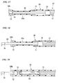
FIG. 1 is a view showing the dissection instrument according to a first embodiment of the present invention. -
FIG. 2 is a partial cross-sectional view showing the inserted part when the high-frequency hook of the dissection instrument shown inFIG. 1 is housed inside the tube. -
FIG. 3A is a partial expanded cross-sectional view showing the three-layer coil of the transmitting member shown inFIG. 2 -
FIG. 3B is a partial expanded cross-sectional view showing a nine-strand coil of the transmitting member shown inFIG. 2 . -
FIG. 4 is a cross-sectional view showing the inserted part when the high-frequency hook has been projected out from the tube. -
FIG. 5 is a view showing the arrangement when a diseased area is treated with the medical treatment endoscope that includes a dissection instrument according to a second embodiment of the present invention. -
FIG. 6 is an overall view of the dissection instrument shown inFIG. 5 . -
FIG. 7 is an essential component cross-sectional view showing the inserted part of the dissection instrument shown inFIG. 6 . -
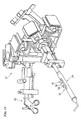
FIG. 8 is a cross-sectional view showing the actuator for the dissection instrument shown inFIG. 5 . -
FIG. 9A is a lateral view of the actuator. -
FIG. 9B is a planar view of the actuator. -
FIG. 10A is an expanded cross-sectional view along the line A-A of the fixing part in the actuator shown inFIG. 8 . -
FIG. 10B is an expanded view of the operating shaft and the fixing hole inFIG. 10A . -
FIG. 11 is an expanded cross-sectional view along the line B-B of the operating member shown inFIG. 8 . -
FIG. 12 is an expanded view of the ratchet mechanism shown inFIG. 8 . -
FIG. 13 is a perspective view of the actuator of the medical treatment endoscope. -
FIG. 14 is a perspective view of the treatment portion that projects out from the opening at the distal end of the medical treatment endoscope shown inFIG. 8 . -
FIG. 15 is an expanded perspective view showing the distal end of the irrigation and suction tube shown inFIG. 5 . -
FIG. 16 is a view showing a modification of the ratchet mechanism shown inFIG. 12 . -
FIG. 17 is a partial cross-sectional view showing a first modification of the distal end of the inserted part. -
FIG. 18 is a view showing an arrangement in which the hook inFIG. 17 is projected out. -
FIG. 19 is a partial cross-sectional view showing a second modification of the distal end of the inserted part. - The endoscope treatment instrument according the first embodiment of the present invention will now be explained with reference to
FIGS. 1 through 4 . -
FIGS. 1 and2 show a soft dissection instrument 1 which is the endoscope treatment instrument according to the first embodiment. This dissection instrument 1 is provided with a flexible insertedpart 2, atreatment portion 3 attached to the distal end of the insertedpart 2, and an actuator 4 connected to the proximal end of the insertedpart 2. - The inserted
part 2 has a flexible shaft, such as a coil sheath, that is inserted inside atube 6, and can be advanced into a body cavity by insertion into the instrument channel of the endoscope. Thetreatment portion 3 is a dissection portion, provided with, for example, a high-frequency hook 3a which serves as a hook consisting of an electrode. The actuator 4 which is provided to the proximal end of the insertedpart 2 is provided with a main body 7 extending in the longitudinal direction of the insertedpart 2, and aslider 8 which can slide with respect to the main body 7. A connectingpart 10 which can be connected to a high-frequency power source is provided to theslider 8, and is electrically conductive with the high-frequency hook 3a via the shaft. - In the inserted
part 2 shown inFIG. 2 , a multiple layer coil, three-layer coil 12 for example, having conductivity is disposed to the proximal end of the high-frequency hook 3a as the distal shaft. The three-layer coil 12 is formed by winding three layers of metal wire in the radial direction such as shown in the expanded view inFIG. 3A , and extends to a length of approximately 200 mm, for example. Multiple layer coils, including three-layer coil 12, have excellent rotation follow-up and are softer and have better bending properties as compared to multiple strand coils. When the insertedpart 2 is inserted into a body cavity, the three-layer coil 12 can form a curved part that can bend or curve in order to incise, etc. the diseased area using the high-frequency hook 3a. - A conductive single layer, multiple strand coil, nine-
strand coil 13 for example, is connected to the proximal end side of the three-layer coil 12 and serves as a long shaft, the length of which is greater than that of the three-layer coil 12. The nine-strand coil 13 is formed by aligning and winding a plurality (nine here) of metal wires as shown inFIG. 3B . As in the case of multiple layer coils, multiple strand coils, including the nine-strand coil 13, has excellent rotation follow-up as compared to a single strand coil, and has the property of greater rigidity as compared to multiple layer coils, including the three-layer coil 12. Multiple strand coils are also very easily moved to advance or retract. Theslider 8 is connected to the proximal end of the nine-strand coil 13 by soldering or other such methods. Note that a shaft is formed by the connection of the three-layer coil 12 and themultiple strand coil 13. - As a result, the
hook 3a can be projected out from thetube 6 via the nine-strand coil 13 and the three-layer coil 12 (seeFIG. 4 ) by advancing theslider 8 along the main body 7 (i.e., movingslider 8 toward thehook 3a side) in the actuator 4, and can be housed within thetube 6 by retracting theslider 8 along the main body 7 (seeFIG. 2 ) in the actuator 4. Further, by rotating the actuator 4, thehook 3a can be rotated by a specific angle via the nine-strand coil 13 and the three-layer coil 12. - Note that the connecting part between the three-
layer coil 12 and the nine-strand coil 13 may be formed as follows, for example. InFIG. 2 , the outer peripheral surfaces near the connection between the three-layer coil 12 and the nine-strand coil 13 are cut out to provide step portions to the outer diameters. The respective step portions of the three-layer coil 12 and the nine-strand coil 13 are inserted into a cylindrical connectingtube 15 which has the same outer diameter as the three-layer coil 12 and the nine-strand coil 13, and engage therewithin. Soldering material is injected into the boundary area between the three-layer coil 12 and the nine-strand coil 13 via a through hole (not shown in the figures) that passes through the connectingtube 15. The inner surface of the connectingtube 15, and the boundary area between the three-layer coil 12 and the nine-strand coil 13, are thus connected by soldering. As a result, the three-layer coil 12 and nine-strand coil 13, and the connectingtube 15, have roughly the same outer diameter along the entire length. - The dissection instrument 1 according to this embodiment is provided with the above-described design. The effects thereof will now be described.
- First, the inserted
part 2 and thetreatment portion 3a of the dissection instrument 1 are inserted into a body cavity via the instrument channel of an endoscope, which is not shown in the figures. The dissection instrument 1 is projected out from the distal end of the endoscope, after which the high-frequency hook 3a is made to project out from thetube 6 by advancing or retracting theslider 8 of the actuator 4 with respect to the main body 7 (seeFIG. 4 ). In this case, since the insertedpart 2, with the exception of its distal end part, is formed of the long nine-strand coil 13, it can be projected forward easily. Further, the three-layer coil 12 on the distal end side is short in length, so that it has only a slight effect on ease of use. The tissue is then incised by bringing the high-frequency hook 3a, through which current is flowing, into contact with the target tissue inside the body cavity. - The actuator 4 may be rotated in the case where the high-
frequency hook 3a does not have the desired orientation with respect to the tissue. The rotational force from rotating actuator 4 is communicated via the nine-strand coil 13 and the three-layer coil 12 inside thetube 6, causing the high-frequency hook 3a to rotate and be positioned with the desired orientation. Moreover, even if the distal end part of the insertedpart 2 bends, it is formed of the highly flexible three-layer coil 12 so that it does not have an effect on the bending posture of the endoscope, and the rotation of the long nine-strand coil 13 can be communicated to the high-frequency hook 3a with certainty. - In the dissection instrument 1 according to the embodiment described above, the rotation follow-up over the entire length of the inserted
part 2 is excellent, and advancing and retracting can be carried out easily using the long nine-strand coil 13. Further, the distal end part of the insertedpart 2 is a three-layer coil 12 so that the bending of the distal end part of the endoscope can be carried out smoothly. Further, communication of the rotation to the high-frequency hook 3a when in the bent state can be carried out with certainty. - Next, another embodiment of the present invention will be explained. Note that parts that are identical or similar to that of the first embodiment will be assigned the same numeric symbol and an explanation thereof will be omitted.
- The endoscope treatment instrument according to the second embodiment will be explained with reference to
FIGS. 5 through 14 . In the explanatory view of the medical treatment endoscope shown inFIG. 5 , amedical treatment endoscope 20 is provided with an endoscope insertedpart 28, the proximal end side thereof being attached to a base via abranch connection 22c. Afirst sheath 22 and asecond sheath 27 extend branching from the proximal end side of thebranch connection 22c. Anactuator 21 of the medical treatment endoscope is provided to the proximal end of thefirst sheath 22. As shown inFIG. 13 , anactuator 65 for operating thejaws 26a of the grippingforceps 26, and anactuator 24 for operating the high-frequency hook 3a of thedissection instrument 23 are disposed in alignment at a specific angle in thisactuator 21 of the medical treatment endoscope. Theseactuators - A plurality of individual channels are provided in the space extending from the
actuator 21 of the medical treatment endoscope to thefirst sheath 22 and the opening at the distal end of the endoscope insertedpart 28. The insertedpart 25 of thedissection instrument 23 according to the second embodiment of the present invention and the inserted part (not shown) of the grippingforceps 26 are inserted respectively into these channels. - A separate channel is provided within the
second sheath 27 and the endoscope insertedpart 28. An irrigation andsuction tube 30 is inserted into this separate channel via astopper 29 that is provided in the proximal end side of thesecond sheath 27, and projects out from the opening at the distal end. An irrigation andsuction device 31, for example, for performing irrigation and suction, is provided at the proximal end of the irrigation andsuction tube 30. - As shown in
FIG. 14 , anarm 25a and anarm 26b are provided at the distal end of the endoscope insertedpart 28. The high-frequency hook 3a of thedissection instrument 23 and thejaws 26a of the grippingforceps 26 project out respectively from the distal end of each of thearms suction tube 30 projects out from the opening of the separate channel at the distal end of the endoscope insertedpart 28. As shown inFIG. 15 , amain opening 30a is provided at the distal end and one ormore side openings 30b are provided to the sides of the irritation andsuction tube 30. The irrigation andsuction tube 30 can provide irrigation to wash away hemorrhage at the diseased area K inside the body cavity, expelling fluid from the main andside openings - Note that a proximal end
side bending part 22a is formed to thefirst sheath 22, and a distal endside bending part 28a is formed to the endoscope insertedpart 28 at its distal opening side. The presence or absence of therespective bending parts first sheath 22 and theendoscope bending part 28 depends on the position of attachment and the method of use, and it is not absolutely essential that the parts be bent. - Next, the
dissection instrument 23 according to the second embodiment will be explained in detail usingFIGS. 6 through 12 .FIG. 6 shows an overall view of thedissection instrument 23 which is inserted into the endoscope insertedpart 28 and thefirst sheath 22 as explained above. Thetube 32 of the insertedpart 25 is provided to the distal end side of theactuator 24, and a high-frequency hook 3a is provided in a manner to permit advancing and retracting from the opening at the distal end of thetube 32. - The internal design of the
dissection instrument 23 will now be explained using the cross-sectional views shown inFIGS. 7 and8 . First, the design of the shaft which is inserted into thetube 32 shown inFIG. 7 will be explained. A relatively flexible multiple layer coil, three-layer coil 12 for example, having good rotation follow-up, is connected by welding, etc. to the proximal end of the high-frequency hook 3a, and serves as a distal shaft. A relatively rigid multiple strand coil, nine-strand coil 13 for example, having good rotation follow-up, is connected to the proximal end of the three-layer coil 12, and serves as an intermediate shaft. The nine-strand coil 13 is long, and its connection with the three-layer coil 12 is fixed by soldering, etc. at the step portions via the connectingtube 15 as explained above. - A relatively flexible multiple layer coil, three-
layer coil 33 for example, which has good rotation follow-up similar to that of the distal shaft, is connected to the proximal end of the long nine-strand coil 13, and serves as the proximal shaft. The connection between the nine-strand coil 13 and the three-layer coil 33, i.e., the proximal shaft, has the same structure as the connection between the nine-strand coil 13 and the three-layer coil 12, i.e., the distal shaft, and is connected by soldering when the connectingtube 15 is in a state of engagement with the step portions of the nine-strand coil 13 and the three-layer coil 33. The mutually connected three-layer coil 12, nine-strand coil 13 and three-layer coil 33 are together referred to as a "shaft". - The respective three-
layer coils side bending part 28a of the endoscope insertedpart 28 and the proximal endside bending part 22a of thefirst sheath 22 in themedical treatment endoscope 20. - The proximal end of the three-
layer coil 33 on the proximal end side engages with the inside of aconcavity 34a in an operatingshaft 34, and is connected there by welding or soldering. This operatingshaft 34 is rigid and extends inside theactuator 24 and is connected to theactuator 24 as described below. - In
FIG. 8 , theactuator 24 is provided with amain body 37 that is roughly tubular. In thisactuator 24, the base of thetube 32 passes through atubular part 36. The base of thetubular part 36 is provided at the distal end of themain body 37, and is attached to the inside of acylindrical member 38 which is supported by the inside of themain body 37 to permit relative rotation. Aflange 38a that projects radially from the distal end of themain body 37 is formed to the distal end of thecylindrical member 38. - The
main body 37 of theactuator 24 is designed to enable rotation with respect to thecylindrical member 38 viaaxes 39 which are provided at the base of thecylindrical member 38. Aguide groove 40 is formed at a central area along the longitudinal direction of themain body 37, and extends longitudinally to a flat centralupper surface 37a (seeFIG. 9A, FIG. 9B ). A fixingpart 41 is disposed to enable sliding within themain body 37 within the limits of theguide groove 40. The fixingpart 41 fixes the operatingshaft 34 which passes through thecylindrical member 38 and extends to the proximal end side. The center axis O of the operatingshift 34 preferably coincides with the center axis O' of themain body 37. - The fixing
part 41 shown inFIG. 8 andFIG. 10A has a first slidingpart 43 that can slide inside themain body 37 and is provided with an internal throughhole 42 that is formed in the direction of sliding. A fixingconcavity 45 is formed to the first slidingpart 43, perpendicular to the throughhole 42. A fixedaxis 44 which extends outward along theguide groove 40 of themain body 37 can be inserted to permit reciprocating motion (vertical motion) within the fixingconcavity 45. Anactuator button 44a is provided to the head on the fixedaxis 44, and a steppedpart 44b is formed in the bottom part of the fixedaxis 44. Acoil spring 47, for example, is attached as an elastic member between the steppedpart 44b and the bottom part of the fixingconcavity 45. As a result, the fixedaxis 44 is biased so as to project out from theguide groove 40. Along hole 46 is formed in the fixedaxis 44, and a regulatingpin 49 which is provided to the first slidingpart 43 is inserted into thislong hole 46. The extent of the reciprocating motion (vertical motion) of the fixedaxis 44 is regulated by thislong hole 46 and regulatingpin 49. - Further, a roughly gourd-shaped
fixing hole 48, in which alarge diameter part 48a and aslit 48b communicate when positioned on top of throughhole 42, is formed in the approximate center of the fixedaxis 44. The base 34b of the operatingshaft 34 is inserted into the fixinghole 48. Thisbase 34b is formed to be roughly oval in cross-section to permit engagement with theslit 48b of the fixinghole 48, as shown inFIG. 10B . - Under ordinary conditions, the
base 34b of the operatingshaft 34 is engaged and fixed in place in theslit 48b of the fixinghole 48 due to the biasing force of thecoil spring 47. The operatingshaft 34 is designed to permit unitary rotation together with themain body 37 around the center axis O of the operatingshaft 34. As a result, it is possible to change the angle of the high-frequency hook 3a with respect to the diseased area K by rotating themain body 37. In addition, by pushing theoperating button 44a of the fixedaxis 44, the fixedaxis 44 is moved toward the bottom of the fixingconcavity 45 against the biasing force of thecoil spring 47, so that the base 34b of the operatingshaft 34 is moved from theslit 48b into thelarge diameter part 48a. The operatingshaft 34 is thereby released from themain body 37. - In
FIG. 8 , an operatingmember 50 is provided adjacent to the fixingpart 41. A roughly cylindrical second slidingpart 51 to which the first slidingpart 43 of the fixingpart 41 is connected by a screw or the like is provided in the operatingmember 50. Together these form a unitary sliding member. These first and second slidingmembers main body 37. A throughhole 51a is formed in the longitudinal direction within the second slidingpart 51. Aratchet member 53 provided withratchet teeth 52 is disposed in a fixed manner inside the throughhole 51a as a support. Thebase 53a of theratchet member 53 engages in a concavity at theproximal end portion 37b of themain body 37. Aconnector 54 which is exposed at theproximal end surface 37c of themain body 37 is attached to the rear of thebase 53a of theratchet member 53. - A
knob 56 which projects outward passing through theguide groove 40 is provided to the second slidingpart 51. Anoperating hole 57 is formed extending in the direction in which theknob 56 and the second slidingpart 51 are perpendicular to the center axis O', and communicates with a throughhole 51a. The operatingaxis 58 is inserted from theknob 56 into the operatinghole 57 so as to permit reciprocating motion (vertical motion) within specific limits. - As shown in
FIG. 11 , the operatingaxis 58 is provided with anoperating button 58a at its head, and a steppedpart 58b at its bottom. The center portion widens to a roughly square shape when seen in vertical cross-section, and awindow 58c is formed penetrating internally. Acoil spring 60 is attached in a compressed state in between the steppedpart 58b that is provided to the bottom of the operatingaxis 58 and thestep 57a that is provided at the bottom of theoperating hole 57,coil spring 60 serving as an elastic member. - The
ratchet teeth 52 of theratchet member 53 and theratchet claw 61 that is provided to thewindow 58c form a ratchet mechanism in which they engage with one another when the operatingaxis 58 is pushed upward under the biasing force of the coil spring 60 (seeFIG. 12 ). The tooth profile of theratchet teeth 52 is formed so that when engaged with theratchet claw 61, for example, the second slidingpart 51 which includes theratchet claw 61 can move in one direction, forward for example, but movement in the opposite direction toward the proximal end is prohibited. Conversely, when theoperating button 58a of the operatingaxis 58 is pushed in against the biasing force of thecoil spring 60, theratchet claw 61 moves away from theratchet teeth 52. Note that it is also acceptable to provide theratchet teeth 52 to thewindow 58c, and to provide theratchet claw 61 to theratchet member 53. - The
ratchet member 53 attached to theconnector 54, the operatingaxis 58, thecoil spring 60, the second slidingpart 51, the first slidingpart 43 of the fixingpart 41, thecoil spring 47, and the fixedaxis 44 are formed of a conductive member, and can transmit electricity to the high-frequency hook 3a via the operatingshaft 34 and the shafts (various coils operating button 58a in the operatingmember 50, theratchet claw 61 of the operatingaxis 58 can be moved away from theratchet teeth 52, thus interrupting current flow between them. - A
space 63 is formed between thecylindrical member 38 and theratchet member 53 inside themain body 37 of theactuator 24, and is designed to permit the first slidingpart 43 of the fixingpart 41 and the second slidingpart 51 of the operatingmember 50 to slide in unison. When theratchet claw 61 is moved away from theratchet teeth 52 by pushing theoperating button 58a of the operatingmember 50, theknob 56 can move forward along theguide groove 40. As a result, the first slidingpart 43 and the second slidingpart 51 move throughinternal space 63 inside themain body 37 in a unitary manner, causing the high-frequency hook 3a to move forward via the fixingpart 41. By moving theknob 56 forward with theratchet claw 61 in a state of engagement with theratchet teeth 52, thehook 3a can be made to project out in a state of conduction. In addition, by rotating themain body 37 about center axis O', the first and second slidingparts shaft 34 to thehook 3a about the same axis. - Note that
FIG. 16 shows an example of a modification of the above-described ratchet mechanism. Theratchet teeth 52A and theratchet claw 61A shown inFIG. 16 form a peaked tooth profile that permits movement of the second slidingpart 51 in the advancing or retracting direction when engaged. As a result, the high-frequency hook 3a can be advanced or retracted with respect to thetube 32 without pushing anoperating button 58a, by moving theknob 56 forward or back when theratchet teeth 52A and theratchet claw 61A are engaged, i.e., when maintaining a state of conduction. - The
medical treatment endoscope 20 equipped with adissection instrument 23 according to the second embodiment is provided with the above-described design. The effects thereof will now be described. - First, the endoscope inserted
part 28 of themedical treatment endoscope 20 is inserted into a body cavity as shown inFIG. 5 .Dissection instrument 23 and grippingforceps 26, for example, are then inserted as treatment instruments via respective channels of the endoscope insertedpart 28, and the front ends thereof are made to project out from thearms distal arms actuator 21 of the medical treatment endoscope, a technician, for example, carries out the procedure on the diseased area K by using his left hand to manipulate theactuator 65 of the grippingforceps 26 and using his right hand to manipulate theactuator 24 of thedissection instrument 23. - For example, the diseased area K is gripped in the
jaws 26a of the grippingforceps 26. Thedissection instrument 23 is moved forward (toward the high-frequency hook 3a side) by moving theknob 56 of theactuator 24 along theguide groove 40. As a result, with theratchet teeth 52 and theratchet claw 61 in a state of engagement, the second slidingpart 51 and the first slidingpart 43 of the fixingpart 41, together with theratchet claw 61, are moved forward through theinternal space 63 of themain body 37, and the operatingshaft 34, which is fixedly attached to the fixingpart 41, moves forward. - The high-
frequency hook 3a is advanced and projected out from the distal opening of thetube 32 via the three-layer coil 33, the nine-strand coil 13, and the three-layer coil 12 inside thetube 32. In particular, of thesecoils strand coil 13 is highly rigid, so that it can be advanced and retracted easily. - When the high-
frequency hook 3a does not have the desired orientation with respect to the diseased area K held by thejaws 26a of the grippingforceps 26, themain body 37 of theactuator 24 is rotated by the desired angle with respect to thecylindrical member 38 around the center axis O'. As a result, since the operatingshaft 34 is fixed to a fixingpart 41 which rotates in unison with themain body 37, the operatingshaft 34 is also rotated around the center axis O. The highly flexible respective threelayer coils parts frequency hook 3a can be adjusted to the specific angle through the communication of the rotation via therespective coils - A power source cord, which is not shown in the figures, is attached to the
connector 54 of theactuator 24. A high-frequency current can be communicated with certainty to the high-frequency hook 3a at the distal end from the connecting part at the rear end, via theratchet member 53, theratchet teeth 52 and ratchetclaw 61 which are in a state of engagement, the second slidingpart 51, the first slidingpart 43, the operatingshaft 34, the shafts (various coils jaws 26a of the grippingforceps 26 can be incised using the high-frequency hook 3a. - Note that when pulling the high-
frequency hook 3a into thetube 32, theknob 56 may be retracted along theguide groove 40 while pushing theoperating button 58a of theactuator 24. Further, in the ratchet mechanism according to the modified example shown inFIG. 16 , it is not necessary to push theoperating button 58a when pulling in thehook 3a. - Further, as necessary during treatment, the irrigation and
suction tube 30 consisting of a flexible tube may be inserted via thesecond sheath 27, and passed though the endoscope insertedpart 28, so that themain opening 30a at its distal end is projected into the vicinity of the diseased area K. Further, when there is hemorrhage or the like around the diseased area K, irrigating fluid may be expelled from the irrigation andsuction device 31 to wash the area, and fluid remaining inside the body may be suctioned out. In particular,side openings 30b are formed near themain opening 30a at the distal end of the irrigation andsuction tube 30, so that irrigation and suction can still be carried out via theseside openings 30b even if themain opening 30a at the distal end is blocked by coming into contact with the body wall. Note that there is no connecting component at the distal end of the irrigation andsuction tube 30, thus there is no concern about such components falling off. - In the
dissection instrument 23 according the second embodiment as described above, highly flexible respective three-layer coils tube 32 are disposed to the distal endside bending part 28a of the endoscope insertedpart 28 and the proximal endside bending part 22a of thefirst sheath 22. As a result, rotation can be sufficiently communicated with having an effect on therespective bending parts coils strand coil 13. As a result, when moving thehook 3a forward or back, it is easy to retract or advance the nine-strand coil 13 without stretching or contracting. - In addition, in the conventional art, when the
connector 54 and the operatingshaft 34 are connected with a cord or the like inside theactuator 24, a disadvantage resulted in that disconnection could easily occur due to the actuator, etc. moving the operatingshaft 34 forward or back. However, in the second embodiment of the present invention, the conduction and cutoff of current to the high-frequency hook 3a at the distal end can be carried out via the ratchet mechanism that is provided inside theactuator 24, so that disconnection is not a concern. - Next, an example of a modification of the
dissection instrument 1, 23 as the endoscope treatment instrument will be explained usingFIGS. 17 through 19 . In thedissection instrument 67 according to the first modification shown inFIGS. 17 and 18 , the distal end of thetube 68 extends further forward than the distal end of the three-layer coil 12 which serves as the distal shaft, and there is formed anopening 68b, the diameter of which is widened by means of asmall diameter part 68a which has been formed with a small diameter. In addition, a rigid rod-shapedelectrode extension 69 which connects the three-layer coil 12 and the high-frequency hook 3a is disposed inside thesmall diameter part 68a. Theelectrode extension 69 forms an electrical single wire, having a length of 100 mm, for example. - A
first stopper 71 for preventing the connectingpart 70 between theelectrode extension 69 and the three-layer coil 12 from projecting forward is provided to the inner peripheral surface of thetube 68. Thetube 68 is positioned on the proximal end side of thesmall diameter part 68a, and has a larger diameter than thesmall diameter part 68a. Asecond stopper 72 for preventing the high-frequency hook 3a from being pulled into thetube 68 is provided to the inner surface of the expandeddiameter opening 68b of thetube 68. - In this modified example, the
tube 68, which during treatment, etc., is projected out from thearm 25a provided to themedical treatment endoscope 20, is reinforced by theelectrode extension 69 that is positioned internally. During dissection operations, theactuator 24 is manipulated to advance the three-layer coil 12, i.e., the distal shaft, within thetube 68 until the connectingpart 70 comes into contact with thefirst stopper 71 and theelectrode extension 69 is projected out from thedistal opening 68b of thetube 68. Dissection is then performed using thehook 3a (seeFIG. 18 ). - Accordingly, as a result of providing a
small diameter part 68a extending from thetube 68, as well as theelectrode extension 69 internally, in thedissection instrument 67 according to this modified example, thetube 68 can be made thinner, facilitating advancing and retracting. Further, since reinforcement can be provided by theelectrode extension 69, bending can be prevented, and the operation of dissection the tissue using thehook 3a can be carried out easily. - Next, in the second modification shown in
FIG. 19 , thetube 68 is formed extending so as to cover theelectrode extension 69, and a stopper 73 is provided on the inner surface of thedistal opening 68b. Theelectrode extension 69 extends inside the three-layer coil 12. When thehook 3a is advanced using theactuator 24, the three-layer coil 12 advances until the connectingpart 70 comes into contact with the stopper 73 inside thetube 68, so that thehook 3a can be projected out. In this case, theelectrode extension 69 is covered by the three-layer coil 12, i.e., the distal shaft, thus increasing the rigidity in this region and making it more difficult for bending to occur. The stopper 73 also prevents thehook 3a from being pulled inside. - While preferred embodiments of the invention have been described and illustrated above, it should be understood that these are exemplary of the invention and are not to be considered as limiting. Additions, omissions, substitutions, and other modifications can be made without departing from the spirit or scope of the present invention.
- For example, single strand multiple layer coils 12, 33 were employed as distal and proximal shafts, respectively, in the above-described embodiment, however, it is also acceptable to form the multiple layer coils 12, 33 using multiple strand coils. In this case, it is necessary to make the metal wires thinner, however flexibility can be maintained due to the use of a multiple layer coil.
- In addition, the various embodiments and modifications described above employed a three-
layer coil strand coil 13 was employed as the second coil sheath, if a multiple strand coil is employed, then the number of aligned metal wires is optional. These form the communicating member. - The invention is not to be considered as being limited by the foregoing description, and is only limited by the scope of the appended claims.
- The following description pages 17 to 18 contain preferred embodiments. Accordingly, the term "claim" as used therein refers to such a "preferred embodiment".
- 1. An endoscope treatment instrument (1, 23, 67, 68) provided with:
- a flexible transmitting member (2);
- a treatment portion (3) that is attached to the distal end of said transmitting member; and
- an actuator (4) which is attached to the proximal end of said transmitting member and is for operating said treatment portion; wherein,
- said endoscope treatment instrument is designed to transmit the action of said actuator to said treatment portion via said transmitting member, and
- said transmitting member consists of the connection in the longitudinal direction of a first coil sheath (12) that has excellent rotation follow-up and good relative bending properties, and a second coil sheath (13) that has excellent rotation follow-up and good ease of motion in the relative longitudinal direction.
- 2. The endoscope treatment instrument according to claim 1, wherein in said transmitting member, said first coil sheath is connected on the treatment portion side, and said second coil sheath is connected on the proximal end side of said first coil sheath.
- 3. The endoscope treatment instrument according to claim 1, wherein in said transmitting member, respective said first coil sheath is connected to the treatment portion side and the actuator side, and said second coil sheath is connected between said first coil sheath.
- 4. The endoscope treatment instrument according to claim 1, wherein said first coil sheath is formed of a multiple layer coil and said second coil sheath is formed of a multiple strand coil.
- 5. The endoscope treatment instrument according to claim 4, wherein said multiple layer coil is formed of a single strand coil or a multiple strand coil.
- 6. The endoscope treatment instrument according to claim 4, wherein said multiple strand coil is a single layer coil.
- 7. An endoscope treatment instrument (23, 67, 68) provided with:
- a flexible transmitting member (25);
- a treatment portion (3a) that is attached to the distal end of said transmitting member; and
- an actuator (24) which is attached to the proximal end of said transmitting member and is for operating said treatment portion; wherein
- said endoscope treatment instrument is designed to transmit the action of said actuator to said treatment portion via said transmitting member;
- said treatment portion is a high-frequency treatment instrument; and
- said actuator is a provided with a sliding body (43, 51) that is electrically connected to said high-frequency treatment instrument via said transmitting member, a support (51a) that is electrically connected to a connector (54), and a ratchet mechanism (53) that is provided to enable electrical conduction or interruption between said sliding body and said support.
- 8. An endoscope treatment instrument according to claim 7, wherein said ratchet mechanism is provided with ratchet teeth (52, 52A) that are provided to one of either said sliding body and said support, and a ratchet claw (61, 61A) that is provided to the other of said sliding body and said support, and which can engage with said ratchet teeth.
- 9. An endoscope treatment instrument according to
claim 8, wherein said sliding body is connected to said transmitting member, and said treatment portion can be advanced and/or retracted via said transmitting member, by advancing and/or retracting said sliding body when said ratchet teeth and said ratchet claw are in a state of engagement. - 10. An endoscope treatment instrument according to
claim 8, wherein said operating member that is provided with one of either said ratchet claw and said ratchet teeth be provided to said sliding body in a manner which permits advancing and retracting, and that said operating member be biased by an elastic member (60) in a direction so as to cause engagement between said ratchet claw and said ratchet teeth and permit electrical conduction, and that the electrical current be interrupted by separating said ratchet claw and said ratchet teeth by moving said operating member in the direction that is opposite the biasing force of said elastic member.
Claims (4)
- An endoscope treatment instrument (23, 67, 68) provided with:a flexible transmitting member (25);a treatment portion (3a) that is attached to the distal end of said transmitting member; andan actuator (24) which is attached to the proximal end of said transmitting member and is for operating said treatment portion; whereinsaid endoscope treatment instrument is designed to transmit the action of said actuator to said treatment portion via said transmitting member;said treatment portion is a high-frequency treatment instrument; andsaid actuator is a provided with a sliding body (43, 51) that is electrically connected to said high-frequency treatment instrument via said transmitting member, a support (51a) that is electrically connected to a connector (54), and a ratchet mechanism (53) that is provided to enable electrical conduction or interruption between said sliding body and said support.
- An endoscope treatment instrument according to claim 1, wherein said ratchet mechanism is provided with ratchet teeth (52, 52A) that are provided to one of either said sliding body and said support, and a ratchet claw (61, 61A) that is provided to the other of said sliding body and said support, and which can engage with said ratchet teeth.
- An endoscope treatment instrument according to claim 2, wherein said sliding body is connected to said transmitting member, and said treatment portion can be advanced and/or retracted via said transmitting member, by advancing and/or retracting said sliding body when said ratchet teeth and said ratchet claw are in a state of engagement.
- An endoscope treatment instrument according to claim 2, wherein said operating member that is provided with one of either said ratchet claw and said ratchet teeth be provided to said sliding body in a manner which permits advancing and retracting, and that said operating member be biased by an elastic member (60) in a direction so as to cause engagement between said ratchet claw and said ratchet teeth and permit electrical conduction, and that the electrical current be interrupted by separating said ratchet claw and said ratchet teeth by moving said operating member in the direction that is opposite the biasing force of said elastic member.
Applications Claiming Priority (2)
| Application Number | Priority Date | Filing Date | Title |
|---|---|---|---|
| US12/057,841 US8728089B2 (en) | 2008-03-28 | 2008-03-28 | Endoscope treatment instrument |
| EP09004188.0A EP2111806B1 (en) | 2008-03-28 | 2009-03-24 | Endoscope treatment instrument |
Related Parent Applications (3)
| Application Number | Title | Priority Date | Filing Date |
|---|---|---|---|
| EP09004188.0A Division EP2111806B1 (en) | 2008-03-28 | 2009-03-24 | Endoscope treatment instrument |
| EP09004188.0A Division-Into EP2111806B1 (en) | 2008-03-28 | 2009-03-24 | Endoscope treatment instrument |
| EP09004188.0 Division | 2009-03-24 |
Publications (3)
| Publication Number | Publication Date |
|---|---|
| EP2386255A2 true EP2386255A2 (en) | 2011-11-16 |
| EP2386255A3 EP2386255A3 (en) | 2013-06-05 |
| EP2386255B1 EP2386255B1 (en) | 2017-04-26 |
Family
ID=40848671
Family Applications (2)
| Application Number | Title | Priority Date | Filing Date |
|---|---|---|---|
| EP11006136.3A Expired - Fee Related EP2386255B1 (en) | 2008-03-28 | 2009-03-24 | Endoscope treatment instrument |
| EP09004188.0A Expired - Fee Related EP2111806B1 (en) | 2008-03-28 | 2009-03-24 | Endoscope treatment instrument |
Family Applications After (1)
| Application Number | Title | Priority Date | Filing Date |
|---|---|---|---|
| EP09004188.0A Expired - Fee Related EP2111806B1 (en) | 2008-03-28 | 2009-03-24 | Endoscope treatment instrument |
Country Status (3)
| Country | Link |
|---|---|
| US (1) | US8728089B2 (en) |
| EP (2) | EP2386255B1 (en) |
| JP (1) | JP5572306B2 (en) |
Families Citing this family (8)
| Publication number | Priority date | Publication date | Assignee | Title |
|---|---|---|---|---|
| JP2012055368A (en) * | 2010-09-06 | 2012-03-22 | Hoya Corp | Hook-like high-frequency knife for flexible endoscope |
| US9060765B2 (en) * | 2010-11-08 | 2015-06-23 | Bovie Medical Corporation | Electrosurgical apparatus with retractable blade |
| JP5132846B2 (en) * | 2010-12-28 | 2013-01-30 | オリンパスメディカルシステムズ株式会社 | Endoscopic treatment tool |
| JP6454563B2 (en) * | 2015-02-12 | 2019-01-16 | 株式会社トップ | Surgical instrument aids |
| CN104970755A (en) * | 2015-06-18 | 2015-10-14 | 北京大学第三医院 | Auxiliary device for superfine endoscope biliary tract detection |
| JP6749545B2 (en) * | 2016-08-02 | 2020-09-02 | 英博 山本 | Thin endoscopic surgical instrument |
| US10799312B2 (en) * | 2017-04-28 | 2020-10-13 | Edwards Lifesciences Corporation | Medical device stabilizing apparatus and method of use |
| CN110719759B (en) | 2017-05-30 | 2023-06-30 | 阿皮克斯医疗股份有限公司 | Electrosurgical device with robotic tip |
Citations (2)
| Publication number | Priority date | Publication date | Assignee | Title |
|---|---|---|---|---|
| JPH0347246A (en) | 1989-04-13 | 1991-02-28 | Olympus Optical Co Ltd | Treating tool for endoscope |
| JP2000229084A (en) | 1999-02-09 | 2000-08-22 | Asahi Optical Co Ltd | Biopsy forceps for endoscopy |
Family Cites Families (18)
| Publication number | Priority date | Publication date | Assignee | Title |
|---|---|---|---|---|
| US3749085A (en) * | 1970-06-26 | 1973-07-31 | J Willson | Vascular tissue removing device |
| JPS55109501U (en) | 1979-01-29 | 1980-07-31 | ||
| DE3704094A1 (en) | 1985-12-13 | 1988-08-18 | Harald Maslanka | Surgical instrument |
| JPH0511842Y2 (en) | 1987-11-13 | 1993-03-25 | ||
| JPH05208014A (en) | 1991-04-10 | 1993-08-20 | Olympus Optical Co Ltd | Treating tool |
| JP2508275Y2 (en) | 1991-04-18 | 1996-08-21 | オリンパス光学工業株式会社 | Endoscope treatment tool |
| JPH055106U (en) | 1991-07-04 | 1993-01-26 | オリンパス光学工業株式会社 | High frequency treatment tool for endoscope |
| JPH055105U (en) | 1991-07-04 | 1993-01-26 | オリンパス光学工業株式会社 | Operation part of treatment tool for endoscope |
| JP2953305B2 (en) | 1994-04-26 | 1999-09-27 | 富士写真光機株式会社 | Ultrasound endoscope device |
| JP3732911B2 (en) | 1996-10-08 | 2006-01-11 | ペンタックス株式会社 | Endoscopic treatment tool |
| US6398791B1 (en) * | 1999-06-11 | 2002-06-04 | Scimed Life Systems Inc | Variable composite sheath with interrupted sections |
| US6409727B1 (en) * | 1999-10-15 | 2002-06-25 | Scimed Life Systems, Inc. | Multifilar flexible rotary shaft and medical instruments incorporating the same |
| EP1392192B1 (en) | 2001-06-05 | 2006-08-16 | Erbe Elektromedizin GmbH | Bipolar clamp |
| JP4691640B2 (en) * | 2003-10-03 | 2011-06-01 | メドトロニック,インコーポレイテッド | Inflatable sheath and device and method of manufacturing the same |
| JP2005204998A (en) | 2004-01-23 | 2005-08-04 | Olympus Corp | Forceps for endoscope |
| JP4504696B2 (en) | 2004-02-03 | 2010-07-14 | オリンパス株式会社 | Endoscopic treatment tool, endoscope, and endoscope treatment system |
| AU2007210011A1 (en) | 2006-01-27 | 2007-08-09 | Medtronic, Inc. | Device and system for surgical dissection and or guidance of other medical devices into body |
| JP4497379B2 (en) | 2006-08-23 | 2010-07-07 | 朝日インテック株式会社 | Medical treatment tool |
-
2008
- 2008-03-28 US US12/057,841 patent/US8728089B2/en active Active
- 2008-12-12 JP JP2008317401A patent/JP5572306B2/en not_active Expired - Fee Related
-
2009
- 2009-03-24 EP EP11006136.3A patent/EP2386255B1/en not_active Expired - Fee Related
- 2009-03-24 EP EP09004188.0A patent/EP2111806B1/en not_active Expired - Fee Related
Patent Citations (2)
| Publication number | Priority date | Publication date | Assignee | Title |
|---|---|---|---|---|
| JPH0347246A (en) | 1989-04-13 | 1991-02-28 | Olympus Optical Co Ltd | Treating tool for endoscope |
| JP2000229084A (en) | 1999-02-09 | 2000-08-22 | Asahi Optical Co Ltd | Biopsy forceps for endoscopy |
Also Published As
| Publication number | Publication date |
|---|---|
| EP2111806A2 (en) | 2009-10-28 |
| EP2386255B1 (en) | 2017-04-26 |
| EP2386255A3 (en) | 2013-06-05 |
| EP2111806B1 (en) | 2014-05-14 |
| JP5572306B2 (en) | 2014-08-13 |
| EP2111806A3 (en) | 2009-11-25 |
| US20090247822A1 (en) | 2009-10-01 |
| JP2009240761A (en) | 2009-10-22 |
| US8728089B2 (en) | 2014-05-20 |
Similar Documents
| Publication | Publication Date | Title |
|---|---|---|
| EP2111806B1 (en) | Endoscope treatment instrument | |
| EP1161174B1 (en) | Controllable endoscopic sheath | |
| JP5265205B2 (en) | Medical equipment | |
| KR102252846B1 (en) | Flexible endoscopic support system | |
| EP1849422A2 (en) | Medical instrument having an articulatable end effector | |
| EP1852073A1 (en) | Medical instrument handle and medical instrument having same | |
| US10149608B2 (en) | Bending portion for endoscope and endoscope including bending portion for endoscope | |
| WO2009117696A1 (en) | Steerable tool guide for use with flexible endoscopic medical devices | |
| ES2899915T3 (en) | Surgeon controlled endoscope device and procedure | |
| US9782197B2 (en) | Tissue grasping device | |
| US10188271B2 (en) | Assist device and endoscope system | |
| JP5671360B2 (en) | Endoscope external channel | |
| JP6482101B2 (en) | Operation unit for bending treatment tools | |
| EP3284422B1 (en) | Hinge member for bendable treatment tool and bendable treatment tool having said hinge member incorporated therein | |
| JP5178369B2 (en) | Endoscopic treatment tool | |
| WO2019202699A1 (en) | Medical device | |
| JP6482051B2 (en) | Hinge member for bending treatment tool and bending treatment tool incorporating the hinge member | |
| JP6810788B2 (en) | Maneuverable catheter handle | |
| JP6856759B2 (en) | Radiofrequency treatment tool and endoscopic system | |
| EP2540211B1 (en) | Endoscope device | |
| WO2019150627A1 (en) | Endoscope | |
| US20170265722A1 (en) | Assistance tool and endoscope system | |
| WO2018070119A1 (en) | Bendable treatment instrument | |
| JP2015128536A (en) | Operation unit for bending treatment instrument | |
| JP7253063B2 (en) | endoscopic instrument |
Legal Events
| Date | Code | Title | Description |
|---|---|---|---|
| 17P | Request for examination filed |
Effective date: 20110726 |
|
| AC | Divisional application: reference to earlier application |
Ref document number: 2111806 Country of ref document: EP Kind code of ref document: P |
|
| AK | Designated contracting states |
Kind code of ref document: A2 Designated state(s): DE FR GB IE |
|
| PUAI | Public reference made under article 153(3) epc to a published international application that has entered the european phase |
Free format text: ORIGINAL CODE: 0009012 |
|
| RAP1 | Party data changed (applicant data changed or rights of an application transferred) |
Owner name: OLYMPUS MEDICAL SYSTEMS CORP. |
|
| PUAL | Search report despatched |
Free format text: ORIGINAL CODE: 0009013 |
|
| AK | Designated contracting states |
Kind code of ref document: A3 Designated state(s): DE FR GB IE |
|
| RIC1 | Information provided on ipc code assigned before grant |
Ipc: A61B 18/12 20060101ALI20130430BHEP Ipc: A61B 17/29 20060101ALN20130430BHEP Ipc: A61B 17/32 20060101AFI20130430BHEP |
|
| RAP1 | Party data changed (applicant data changed or rights of an application transferred) |
Owner name: OLYMPUS CORPORATION |
|
| RAP1 | Party data changed (applicant data changed or rights of an application transferred) |
Owner name: OLYMPUS CORPORATION |
|
| RAP1 | Party data changed (applicant data changed or rights of an application transferred) |
Owner name: OLYMPUS CORPORATION |
|
| RIN1 | Information on inventor provided before grant (corrected) |
Inventor name: MOTAI, KOUSUKE Inventor name: OKADA, TSUTOMU |
|
| RIC1 | Information provided on ipc code assigned before grant |
Ipc: A61B 17/29 20060101ALN20160930BHEP Ipc: A61B 18/12 20060101ALI20160930BHEP Ipc: A61B 17/32 20060101AFI20160930BHEP |
|
| GRAP | Despatch of communication of intention to grant a patent |
Free format text: ORIGINAL CODE: EPIDOSNIGR1 |
|
| STAA | Information on the status of an ep patent application or granted ep patent |
Free format text: STATUS: GRANT OF PATENT IS INTENDED |
|
| RIC1 | Information provided on ipc code assigned before grant |
Ipc: A61B 17/29 20060101ALN20161019BHEP Ipc: A61B 17/32 20060101AFI20161019BHEP Ipc: A61B 18/12 20060101ALI20161019BHEP |
|
| RIC1 | Information provided on ipc code assigned before grant |
Ipc: A61B 17/29 20060101ALN20161021BHEP Ipc: A61B 18/12 20060101ALI20161021BHEP Ipc: A61B 17/32 20060101AFI20161021BHEP |
|
| INTG | Intention to grant announced |
Effective date: 20161115 |
|
| RIN1 | Information on inventor provided before grant (corrected) |
Inventor name: MOTAI, KOUSUKE Inventor name: OKADA, TSUTOMU |
|
| GRAS | Grant fee paid |
Free format text: ORIGINAL CODE: EPIDOSNIGR3 |
|
| GRAA | (expected) grant |
Free format text: ORIGINAL CODE: 0009210 |
|
| STAA | Information on the status of an ep patent application or granted ep patent |
Free format text: STATUS: THE PATENT HAS BEEN GRANTED |
|
| AC | Divisional application: reference to earlier application |
Ref document number: 2111806 Country of ref document: EP Kind code of ref document: P |
|
| AK | Designated contracting states |
Kind code of ref document: B1 Designated state(s): DE FR GB IE |
|
| REG | Reference to a national code |
Ref country code: GB Ref legal event code: FG4D |
|
| REG | Reference to a national code |
Ref country code: IE Ref legal event code: FG4D |
|
| REG | Reference to a national code |
Ref country code: DE Ref legal event code: R096 Ref document number: 602009045776 Country of ref document: DE |
|
| REG | Reference to a national code |
Ref country code: DE Ref legal event code: R097 Ref document number: 602009045776 Country of ref document: DE |
|
| PLBE | No opposition filed within time limit |
Free format text: ORIGINAL CODE: 0009261 |
|
| STAA | Information on the status of an ep patent application or granted ep patent |
Free format text: STATUS: NO OPPOSITION FILED WITHIN TIME LIMIT |
|
| 26N | No opposition filed |
Effective date: 20180129 |
|
| GBPC | Gb: european patent ceased through non-payment of renewal fee |
Effective date: 20180324 |
|
| REG | Reference to a national code |
Ref country code: IE Ref legal event code: MM4A |
|
| PG25 | Lapsed in a contracting state [announced via postgrant information from national office to epo] |
Ref country code: IE Free format text: LAPSE BECAUSE OF NON-PAYMENT OF DUE FEES Effective date: 20180324 |
|
| PG25 | Lapsed in a contracting state [announced via postgrant information from national office to epo] |
Ref country code: GB Free format text: LAPSE BECAUSE OF NON-PAYMENT OF DUE FEES Effective date: 20180324 |
|
| PG25 | Lapsed in a contracting state [announced via postgrant information from national office to epo] |
Ref country code: FR Free format text: LAPSE BECAUSE OF NON-PAYMENT OF DUE FEES Effective date: 20180331 |
|
| PGFP | Annual fee paid to national office [announced via postgrant information from national office to epo] |
Ref country code: DE Payment date: 20190321 Year of fee payment: 11 |
|
| REG | Reference to a national code |
Ref country code: DE Ref legal event code: R119 Ref document number: 602009045776 Country of ref document: DE |
|
| PG25 | Lapsed in a contracting state [announced via postgrant information from national office to epo] |
Ref country code: DE Free format text: LAPSE BECAUSE OF NON-PAYMENT OF DUE FEES Effective date: 20201001 |