EP2386162B1 - Verfahren und vorrichtung zur kanalschätzung unter verwendung von mehreren beschreibungscodes - Google Patents
Verfahren und vorrichtung zur kanalschätzung unter verwendung von mehreren beschreibungscodes Download PDFInfo
- Publication number
- EP2386162B1 EP2386162B1 EP09760444.1A EP09760444A EP2386162B1 EP 2386162 B1 EP2386162 B1 EP 2386162B1 EP 09760444 A EP09760444 A EP 09760444A EP 2386162 B1 EP2386162 B1 EP 2386162B1
- Authority
- EP
- European Patent Office
- Prior art keywords
- channel
- channel vector
- vector
- station
- codebook
- Prior art date
- Legal status (The legal status is an assumption and is not a legal conclusion. Google has not performed a legal analysis and makes no representation as to the accuracy of the status listed.)
- Active
Links
- 238000000034 method Methods 0.000 title claims description 48
- 239000013598 vector Substances 0.000 claims description 298
- 239000011159 matrix material Substances 0.000 claims description 26
- 238000004891 communication Methods 0.000 claims description 24
- 238000004590 computer program Methods 0.000 claims description 2
- 238000013461 design Methods 0.000 description 47
- 230000008569 process Effects 0.000 description 24
- 230000004044 response Effects 0.000 description 13
- 230000015654 memory Effects 0.000 description 9
- 230000005540 biological transmission Effects 0.000 description 8
- 238000005516 engineering process Methods 0.000 description 8
- 238000010586 diagram Methods 0.000 description 6
- 230000006870 function Effects 0.000 description 4
- 238000013139 quantization Methods 0.000 description 4
- 230000002596 correlated effect Effects 0.000 description 3
- 238000001914 filtration Methods 0.000 description 3
- 230000003287 optical effect Effects 0.000 description 3
- 238000012935 Averaging Methods 0.000 description 2
- 238000001514 detection method Methods 0.000 description 2
- 239000000835 fiber Substances 0.000 description 2
- 230000008520 organization Effects 0.000 description 2
- 239000002245 particle Substances 0.000 description 2
- 238000012545 processing Methods 0.000 description 2
- 230000001413 cellular effect Effects 0.000 description 1
- 230000000875 corresponding effect Effects 0.000 description 1
- 238000000354 decomposition reaction Methods 0.000 description 1
- 230000000694 effects Effects 0.000 description 1
- 238000005562 fading Methods 0.000 description 1
- 230000007774 longterm Effects 0.000 description 1
- 238000010295 mobile communication Methods 0.000 description 1
- 238000012986 modification Methods 0.000 description 1
- 230000004048 modification Effects 0.000 description 1
- 238000007781 pre-processing Methods 0.000 description 1
- 238000001228 spectrum Methods 0.000 description 1
- 238000012549 training Methods 0.000 description 1
- 238000012546 transfer Methods 0.000 description 1
Images


Classifications
-
- H—ELECTRICITY
- H04—ELECTRIC COMMUNICATION TECHNIQUE
- H04B—TRANSMISSION
- H04B7/00—Radio transmission systems, i.e. using radiation field
- H04B7/02—Diversity systems; Multi-antenna system, i.e. transmission or reception using multiple antennas
- H04B7/04—Diversity systems; Multi-antenna system, i.e. transmission or reception using multiple antennas using two or more spaced independent antennas
- H04B7/0413—MIMO systems
- H04B7/0417—Feedback systems
-
- H—ELECTRICITY
- H04—ELECTRIC COMMUNICATION TECHNIQUE
- H04L—TRANSMISSION OF DIGITAL INFORMATION, e.g. TELEGRAPHIC COMMUNICATION
- H04L1/00—Arrangements for detecting or preventing errors in the information received
- H04L1/0001—Systems modifying transmission characteristics according to link quality, e.g. power backoff
- H04L1/0033—Systems modifying transmission characteristics according to link quality, e.g. power backoff arrangements specific to the transmitter
- H04L1/0035—Systems modifying transmission characteristics according to link quality, e.g. power backoff arrangements specific to the transmitter evaluation of received explicit signalling
-
- H—ELECTRICITY
- H04—ELECTRIC COMMUNICATION TECHNIQUE
- H04B—TRANSMISSION
- H04B17/00—Monitoring; Testing
- H04B17/20—Monitoring; Testing of receivers
- H04B17/24—Monitoring; Testing of receivers with feedback of measurements to the transmitter
-
- H—ELECTRICITY
- H04—ELECTRIC COMMUNICATION TECHNIQUE
- H04B—TRANSMISSION
- H04B7/00—Radio transmission systems, i.e. using radiation field
- H04B7/02—Diversity systems; Multi-antenna system, i.e. transmission or reception using multiple antennas
- H04B7/04—Diversity systems; Multi-antenna system, i.e. transmission or reception using multiple antennas using two or more spaced independent antennas
- H04B7/06—Diversity systems; Multi-antenna system, i.e. transmission or reception using multiple antennas using two or more spaced independent antennas at the transmitting station
- H04B7/0613—Diversity systems; Multi-antenna system, i.e. transmission or reception using multiple antennas using two or more spaced independent antennas at the transmitting station using simultaneous transmission
- H04B7/0615—Diversity systems; Multi-antenna system, i.e. transmission or reception using multiple antennas using two or more spaced independent antennas at the transmitting station using simultaneous transmission of weighted versions of same signal
- H04B7/0619—Diversity systems; Multi-antenna system, i.e. transmission or reception using multiple antennas using two or more spaced independent antennas at the transmitting station using simultaneous transmission of weighted versions of same signal using feedback from receiving side
- H04B7/0621—Feedback content
- H04B7/0626—Channel coefficients, e.g. channel state information [CSI]
-
- H—ELECTRICITY
- H04—ELECTRIC COMMUNICATION TECHNIQUE
- H04B—TRANSMISSION
- H04B7/00—Radio transmission systems, i.e. using radiation field
- H04B7/02—Diversity systems; Multi-antenna system, i.e. transmission or reception using multiple antennas
- H04B7/04—Diversity systems; Multi-antenna system, i.e. transmission or reception using multiple antennas using two or more spaced independent antennas
- H04B7/06—Diversity systems; Multi-antenna system, i.e. transmission or reception using multiple antennas using two or more spaced independent antennas at the transmitting station
- H04B7/0613—Diversity systems; Multi-antenna system, i.e. transmission or reception using multiple antennas using two or more spaced independent antennas at the transmitting station using simultaneous transmission
- H04B7/0615—Diversity systems; Multi-antenna system, i.e. transmission or reception using multiple antennas using two or more spaced independent antennas at the transmitting station using simultaneous transmission of weighted versions of same signal
- H04B7/0619—Diversity systems; Multi-antenna system, i.e. transmission or reception using multiple antennas using two or more spaced independent antennas at the transmitting station using simultaneous transmission of weighted versions of same signal using feedback from receiving side
- H04B7/0621—Feedback content
- H04B7/0634—Antenna weights or vector/matrix coefficients
-
- H—ELECTRICITY
- H04—ELECTRIC COMMUNICATION TECHNIQUE
- H04B—TRANSMISSION
- H04B7/00—Radio transmission systems, i.e. using radiation field
- H04B7/02—Diversity systems; Multi-antenna system, i.e. transmission or reception using multiple antennas
- H04B7/04—Diversity systems; Multi-antenna system, i.e. transmission or reception using multiple antennas using two or more spaced independent antennas
- H04B7/06—Diversity systems; Multi-antenna system, i.e. transmission or reception using multiple antennas using two or more spaced independent antennas at the transmitting station
- H04B7/0613—Diversity systems; Multi-antenna system, i.e. transmission or reception using multiple antennas using two or more spaced independent antennas at the transmitting station using simultaneous transmission
- H04B7/0615—Diversity systems; Multi-antenna system, i.e. transmission or reception using multiple antennas using two or more spaced independent antennas at the transmitting station using simultaneous transmission of weighted versions of same signal
- H04B7/0619—Diversity systems; Multi-antenna system, i.e. transmission or reception using multiple antennas using two or more spaced independent antennas at the transmitting station using simultaneous transmission of weighted versions of same signal using feedback from receiving side
- H04B7/0636—Feedback format
- H04B7/0639—Using selective indices, e.g. of a codebook, e.g. pre-distortion matrix index [PMI] or for beam selection
-
- H—ELECTRICITY
- H04—ELECTRIC COMMUNICATION TECHNIQUE
- H04L—TRANSMISSION OF DIGITAL INFORMATION, e.g. TELEGRAPHIC COMMUNICATION
- H04L1/00—Arrangements for detecting or preventing errors in the information received
- H04L1/0001—Systems modifying transmission characteristics according to link quality, e.g. power backoff
- H04L1/0023—Systems modifying transmission characteristics according to link quality, e.g. power backoff characterised by the signalling
- H04L1/0026—Transmission of channel quality indication
-
- H—ELECTRICITY
- H04—ELECTRIC COMMUNICATION TECHNIQUE
- H04L—TRANSMISSION OF DIGITAL INFORMATION, e.g. TELEGRAPHIC COMMUNICATION
- H04L25/00—Baseband systems
- H04L25/02—Details ; arrangements for supplying electrical power along data transmission lines
- H04L25/0202—Channel estimation
- H04L25/024—Channel estimation channel estimation algorithms
- H04L25/0242—Channel estimation channel estimation algorithms using matrix methods
-
- H—ELECTRICITY
- H04—ELECTRIC COMMUNICATION TECHNIQUE
- H04L—TRANSMISSION OF DIGITAL INFORMATION, e.g. TELEGRAPHIC COMMUNICATION
- H04L25/00—Baseband systems
- H04L25/02—Details ; arrangements for supplying electrical power along data transmission lines
- H04L25/0202—Channel estimation
- H04L25/024—Channel estimation channel estimation algorithms
- H04L25/0256—Channel estimation using minimum mean square error criteria
Definitions
- the present disclosure relates generally to communication, and more specifically to techniques for performing channel estimation in a wireless communication system.
- Wireless communication systems are widely deployed to provide various communication content such as voice, video, packet data, messaging, broadcast, etc. These wireless systems may be multiple-access systems capable of supporting multiple users by sharing the available system resources. Examples of such multiple-access systems include Code Division Multiple Access (CDMA) systems, Time Division Multiple Access (TDMA) systems, Frequency Division Multiple Access (FDMA) systems, Orthogonal FDMA (OFDMA) systems, and Single-Carrier FDMA (SC-FDMA) systems.
- CDMA Code Division Multiple Access
- TDMA Time Division Multiple Access
- FDMA Frequency Division Multiple Access
- OFDMA Orthogonal FDMA
- SC-FDMA Single-Carrier FDMA
- a transmitter may send a data transmission from multiple (K) transmit antennas to one or more (R) receive antennas at a receiver.
- a wireless channel between the K transmit antennas and the R receive antennas may include a propagation channel from each transmit antenna to each receive antenna.
- the propagation channels for all transmit and receive antennas may observe different fading and multipath effects and may be associated with different complex channel gains. Good performance may be obtained for the data transmission if an accurate estimate of the wireless channel response is available. Techniques that can provide an accurate channel estimate may thus be desirable.
- Multi-Codebook Pre-coding Scheme for MIMO in E-UTRA Downlink 3GPP, R1-070856
- MB Multi-Codebook
- Document US 2008/0232503 A1 discusses a MIMO wireless communication system employing a variable size preceding codebook.
- the size of the codebook may be determined by the quality of the wireless transmission channel between a transmitter and a receiver associated with the MIMO wireless communication systems or some other codebook selection criteria
- MDC multiple description codes
- a set of codebooks may be used for quantizing measured channel vectors.
- Each codebook may include a different set of channel vectors or codewords.
- Different codebooks may be selected in different reporting intervals to quantize the measured channel vectors obtained in these reporting intervals. The use of different codebooks may improve channel estimation accuracy.
- a receiver may obtain an initial/measured channel vector for a communication channel.
- the initial channel vector may be an estimate of the response of the communication channel.
- the receiver may select a codebook in a set of codebooks for quantizing the initial channel vector.
- the receiver may then select a channel vector in the selected codebook based on the initial channel vector. For example, the receiver may select a channel vector with (i) a largest correlation with a normalized channel vector or (ii) a smallest distance to the initial channel vector.
- the receiver may send the selected channel vector and possibly the selected codebook to a transmitter.
- the transmitter may receive a plurality of reported channel vectors sent by the receiver in a plurality of reporting intervals. Each reported channel vector may be a channel vector selected by the receiver based on an initial channel vector. The transmitter may derive a final channel vector for the communication channel based on the reported channel vectors. In one design, the transmitter may remove phase ambiguity in the reported channel vectors to obtain phase corrected channel vectors. The transmitter may then form multiple intermediate channel vectors for multiple transmit antennas at the transmitter based on the phase corrected channel vectors. Each intermediate channel vector may include channel gains for one transmit antenna in the phase corrected channel vectors. In another design, the transmitter may form each intermediate channel vector with channel gains for one transmit antenna in the reported channel vectors, without removing the phase ambiguity. For both designs, the transmitter may derive a channel gain for each transmit antenna based on (e.g., by filtering) the intermediate channel vector for that transmit antenna. The final channel vector may include multiple channel gains for the multiple transmit antennas.
- a CDMA system may implement a radio technology such as Universal Terrestrial Radio Access (UTRA), cdma2000, etc.
- UTRA includes Wideband CDMA (WCDMA) and other variants of CDMA.
- cdma2000 covers IS-2000, IS-95 and IS-856 standards.
- a TDMA system may implement a radio technology such as Global System for Mobile Communications (GSM).
- GSM Global System for Mobile Communications
- An OFDMA system may implement a radio technology such as Evolved UTRA (E-UTRA), Ultra Mobile Broadband (UMB), IEEE 802.11 (Wi-Fi), IEEE 802.16 (WiMAX), IEEE 802.20, Flash-OFDM®, etc.
- E-UTRA and E-UTRA are part of Universal Mobile Telecommunication System (UMTS).
- 3GPP Long Term Evolution (LTE) and LTE-Advanced (LTE-A) are new releases of UMTS that use E-UTRA, which employs OFDMA on the downlink and SC-FDMA on the uplink.
- UTRA, E-UTRA, UMTS, LTE, LTE-A and GSM are described in documents from an organization named "3rd Generation Partnership Project" (3GPP).
- cdma2000 and UMB are described in documents from an organization named "3rd Generation Partnership Project 2" (3GPP2).
- the techniques described herein may be used for the systems and radio technologies mentioned above as well as other systems and radio technologies.
- FIG. 1 shows a block diagram of a design of a transmitter 110 and a receiver 150 in a wireless communication system.
- transmitter 110 may be part of a base station
- receiver 150 may be part of a user equipment (UE)
- UE user equipment
- a data transmission may be sent on the downlink from the base station to the UE.
- transmitter 110 may be part of a UE
- receiver 150 may be part of a base station
- a data transmission may be sent on the uplink from the UE to the base station.
- Transmitter 110 and receiver 150 may also be part of other entities.
- transmitter 110 is equipped with multiple (K) transmit antennas 132a through 132k
- receiver 150 is equipped with a single receive antenna 152.
- a multiple-input single-output (MISO) channel is formed between the K transmit antennas 132a through 132k and the single receive antenna 152.
- MISO multiple-input single-output
- the MISO channel may be assumed to be flat in frequency but correlated in time due to low user mobility.
- a transmit processor 120 may generate and provide pilot symbols to K transmitter units (TMTR) 130a through 130k.
- the pilot symbols may be modulation symbols known a priori by transmitter 110 and receiver 150 and may also be referred to as reference symbols, training symbols, etc.
- Transmitter units 130a through 130k may process the pilot symbols and generate K modulated signals, which may be transmitted via antennas 132a through 132k, respectively.
- antenna 152 may receive the modulated signals from transmitter 110 and may provide a received signal to a receiver unit (RCVR) 154.
- Receiver unit 154 may process the received signal and provide received symbols to a receive channel estimator 160.
- Channel estimator 160 may estimate the response of the MISO channel based on the received symbols for the pilot symbols and may provide an initial channel estimate comprising an initial channel vector h '( n ), which may be an estimate of the actual channel vector h ( n ).
- Receiver 150 may quantize the K channel gains in vector h' ( n ) and may send the K quantized channel gains as feedback to transmitter 110. Many bits may be needed to send the K quantized channel gains.
- a codebook containing M channel vectors may be defined.
- Each channel vector may be referred to as a codeword of the codebook and may be assigned a unique B-bit index.
- B may be equal to four
- the codebook may contain 16 channel vectors, and each channel vector may be assigned a unique 4-bit index.
- a channel vector in the codebook that most closely matches the initial channel vector h' ( n ) may be selected and denoted as g(n).
- the B-bit index of the selected channel vector may be sent by receiver 150 to transmitter 110.
- the use of a codebook to quantize the initial channel vector h' ( n ) may greatly reduce the amount of information to send back.
- the selected channel vector g ( n ) has quantization errors, which may degrade the accuracy of a channel estimate derived by transmitter 110.
- Quantization errors may be reduced by using a larger codebook.
- a larger codebook may result in more processing at receiver 150 to evaluate all of the codewords as well as more bits being used to convey the selected codeword.
- MDC multiple description codes
- MDC refers to the use of multiple code descriptions to improve the accuracy of source representation at a source.
- different codebooks with similar statistical properties may be used in different channel feedback reporting intervals. The use of different codebooks may improve channel estimation accuracy.
- MDC may be used to quantize time-domain channel estimates to exploit channel correlation across time for low mobility UEs. MDC may also be used to quantize frequency-domain channel estimates (e.g., across subcarriers), which may be applicable for channels with moderate/low frequency selectivity. MDC may also be used to quantize time-frequency (2D) channel estimates. For clarity, much of the description below covers the use of MDC to quantize time-domain channel estimates.
- Channel feedback with MDC may be used for both full channel feedback and channel direction feedback.
- both the channel norm/magnitude and direction may be fed back.
- a codebook for full channel feedback may include M channel vectors having different norms and directions.
- the normalized channel vector includes channel direction information and has unit norm, so that the norm of the channel is not fed back.
- a codebook for channel direction feedback may include M channel vectors of unit norm.
- T codebooks For channel direction feedback with MDC, multiple (T) codebooks with good statistical properties may be generated. This may be achieved by selecting T best codebooks from a large set of potential codebooks such that an outage normalized correlation is maximized at a target outage probability, e.g., 0.001.
- the potential codebooks may be randomly generated Gaussian codebooks.
- Outage normalized correlation may be described as follows.
- An outage normalized correlation may be defined as a value such that the normalized correlation between an actual channel vector h and a reported channel vector g will be less than or equal to this value with a probability of ⁇ , which is the outage probability.
- the value of ⁇ such that ⁇ percent of the figure of merit for all channel realization is worse may be determined and provided as the outage normalized correlation for codebook G j .
- the process may be repeated to determine the outage normalized correlation for each potential codebook.
- the T potential codebooks with the T highest outage normalized correlations may be selected as the T best codebooks. These T best codebooks would have the largest value of ⁇ such that the largest correlation max 1 ⁇ m ⁇ M g m H h 2 is less than or equal to ⁇ ⁇ h ⁇ 2 with a probability of ⁇ .
- the normalized correlation comes from comparing the correlation against the norm of h scaled by ⁇ .
- the T best codebooks may also be selected or defined in other manners.
- the outage normalized correlation may be indicative of how accurate a reported channel vector is to an actual channel vector.
- a larger outage normalized correlation may correspond to better accuracy in the reported channel vector, and vice versa.
- the target outage probability may be indicative of the percentage of time the reported channel vector does not meet the outage normalized correlation.
- a smaller target outage probability i.e., a smaller ⁇
- a smaller outage normalized correlation i.e., a smaller ⁇
- the T codebooks selected for use may include different sets of channel vectors.
- the T codebooks may be stored in a memory 164 at receiver 150 and also in a memory 142 at transmitter 110.
- quantizer 162 may select the channel vector with the largest correlation as a reported channel vector g ( n ), which may be the best quantized version of the normalized channel vector. In one design, quantizer 162 may provide both the index of the selected channel vector as well as the index of the selected codebook as channel feedback information. In another design, transmitter 110 may know ⁇ priori the scheme used by receiver 150 to select codebooks, and quantizer 162 may provide only the index of the selected channel vector as channel feedback information. For both designs, the channel feedback information may be processed by a transmit processor 170 and transmitted via a transmitter unit 172 to transmitter 110.
- the signal from receiver 150 may be processed by a receiver unit 138 to recover the reported channel vector g ( n ).
- a transmit channel estimator 140 may receive the reported channel vector and derive a final channel estimate comprising a final channel vector ⁇ ( n + ⁇ ) based on the L most recent reported channel vectors g ( n ) through g ( n -L-1), where L may be any value greater than one.
- the final channel vector ⁇ ( n ⁇ ) may be an estimate of the MISO channel response at time n + ⁇ , where in general ⁇ ⁇ 0.
- channel estimator 140 may first pre-process the reported channel vectors to remove phase ambiguity.
- the actual channel vector h ( n ) may include K complex channel gains h k ( n ) , for 1 ⁇ k ⁇ K, as shown in equation (1).
- the intermediate channel vector g k may include L channel gains for transmit antenna k in the L most recent reported channel vectors.
- each channel gain h k ( n ) in the actual channel vector h ( n ) may be estimated independently based on the intermediate channel vector g k using a minimum mean square error (MMSE) filter.
- MMSE minimum mean square error
- the covariance matrix and the correlation vector may be calculated empirically with an assumption on the speed of a UE, which may correspond to transmitter 110 or receiver 150.
- g k may be determined for a number of channel realizations based on a particular channel model and may be used to compute the covariance matrix and the correlation vector.
- the wireless channel may be assumed to have a flat Doppler power spectrum for an assumed UE speed.
- the assumed UE speed may be selected to be relatively high for robustness, e.g., 5 to 10 kilometers/hour.
- the covariance matrix and the correlation vector may be calculated (i) empirically based on a particular channel model or (ii) in real time based on the reported channel vectors.
- Different MMSE filters may be defined for different transmit antennas based on the covariance matrices and the correlation vectors for these antennas.
- the components of the final channel vector ⁇ ( n + ⁇ ) may also be determined in other manners.
- ⁇ k ( n + ⁇ ) may be obtained by averaging the L channel gains in the intermediate channel vector g k .
- T codebooks with good statistical properties may be generated. This may be achieved by selecting T codebooks from a large set of potential codebooks (e.g., randomly generated Gaussian codebooks) such that an outage Euclidean distance is minimized at a target outage probability, e.g., 0.001.
- Outage Euclidean distance may be defined in similar manner as outage normalized correlation, except that Euclidean distance instead of normalized correlation is used as a metric.
- An outage Euclidean distance may be defined as a value such that the Euclidean distance between an actual channel vector h and a reported channel vector g will be less than or equal to this value with a probability of ⁇ , which is the outage probability.
- the T codebooks selected for use may include different sets of channel vectors.
- receiver 150 may select the channel vector closest to the initial channel vector in the sense of Euclidean distance. Receiver 150 may provide the index of the selected channel vector g ( n ) and possibly the index of the selected codebook as channel feedback information.
- Transmitter 110 may receive the reported channel vector g ( n ) and may derive a final channel vector ⁇ ( n + ⁇ ) based on the L most recent reported channel vectors g(n) through g ( n -L-1). For full channel feedback, transmitter 110 may omit the pre-processing to remove phase ambiguity. This step may be omitted due to the use of different methods to define the codebooks for channel direction feedback and full channel feedback. Transmitter 110 may form K intermediate channel vectors g k , for 1 ⁇ k ⁇ K, based on the L reported channel vectors. Transmitter 110 may then determine the channel gains in the final channel vector based on the intermediate channel vectors, e.g., using MMSE filters. The channel gains in the final channel vector may also be determined in other manners, e.g., with averaging.
- FIG. 2 shows a block diagram of a design of a transmitter 210 and a receiver 250 in a wireless communication system.
- transmitter 210 is equipped with multiple (K) transmit antennas 232a through 232k
- receiver 250 is equipped with multiple (R) receive antennas 252a through 252r.
- a multiple-input multiple-output (MIMO) channel is formed between the K transmit antennas 232 and the R receive antennas 252.
- the MIMO channel may be assumed to be flat in frequency but correlated in time due to low user mobility.
- a transmit processor 220 may generate and provide pilot symbols to K transmitter units 230a through 230k.
- Transmitter units 230a through 230k may process the pilot symbols and generate K modulated signals, which may be transmitted via K antennas 232a through 232k.
- R antennas 252a through 252r may receive the modulated signals from transmitter 210, and each antenna 252 may provide a respective received signal to an associated receiver unit 254.
- Each receiver unit 254 may process its received signal and provide received symbols to a receive channel estimator 260.
- Channel estimator 260 may estimate the response of a MIMO channel based on the received symbols for the pilot symbols and may provide an initial channel estimate comprising an initial channel matrix H' ( n ).
- the initial channel matrix H' ( n ) may also be represented as an initial channel vector h' ( n ).
- a quantizer 262 may receive the initial channel matrix and perform quantization. In one design, quantizer 262 may ignore the correlation between the R receive antennas and may treat each receive antenna independently. In this design, each row of the initial channel matrix H' ( n ) may be treated as a separate initial channel vector h r ′ n that may be processed as described above for FIG. 1 to obtain a corresponding reported channel vector g r ( n ), for 1 ⁇ r ⁇ R. Quantizer 262 may select one codebook for all R receive antennas or may select different codebooks for different receive antennas. Quantizer 262 may provide R reported channel vectors for the R receive antennas.
- quantizer 262 may exploit the correlation between the R receive antennas and may treat the initial channel matrix as one long initial channel vector h' ( n ) of length K ⁇ R.
- the long initial channel vector may be processed as described above for FIG. 1 to obtain a long reported channel vector g ( n ).
- quantizer 262 may provide channel feedback information, which may comprise R reported channel vectors or one long reported channel vector and possibly the selected codebook(s).
- the channel feedback information may be processed by a transmit processor 270 and transmitted via a transmitter unit 272 to transmitter 210.
- a receiver unit 238 may process the signal from receiver 250 and provide the R reported channel vectors or one long reported channel vector.
- a transmit channel estimator 240 may derive a final channel matrix ⁇ ( n + ⁇ ) based on the reported channel vectors for the L most recent reporting intervals.
- the final channel matrix ⁇ ( n + ⁇ ) may also be represented as a final channel vector ⁇ ( n + ⁇ ).
- channel estimator 240 may derive a final channel vector ⁇ r ( n + ⁇ ) for each receive antenna based on the L most recent reported channel vectors g r ( n ) through g r ( n - L-1) for that receive antenna, as described above. If one long reported channel vector g ( n ) is sent in each reporting interval, then channel estimator 240 may derive a final long channel vector ⁇ ( n + ⁇ ) for all R receive antennas based on the L most recent long reported channel vectors g ( n ) through g ( n -L-1). Channel estimator 240 may then demultiplex the final long channel vector to obtain a final channel vector ⁇ r ( n + ⁇ ) for each receive antenna.
- a channel matrix for a MIMO channel may be converted to an equivalent channel matrix by assuming certain receiver spatial filtering/ processing.
- One or more columns of H eq ( n ) may be quantized using MDC and may be provided as channel feedback information.
- the equivalent channel matrix may also be defined in other manners, e.g., assuming other receiver spatial filtering.
- the techniques described herein may allow a transmitter to derive a more accurate channel estimate based on multiple reported channel vectors for different reporting intervals.
- the use of different codebooks in different reporting intervals may allow a receiver to capture the channel response with different representations. These different representations may reduce quantization errors and improve accuracy when combined at the transmitter, e.g., using MMSE filters.
- the techniques may improve channel estimation performance, which may in turn improve data transmission performance.
- FIG. 3 shows a design of a process 300 for reporting channel feedback for a communication channel from a first station to a second station.
- Process 300 may be performed by the second station, which may be a UE, a base station, or some other entity.
- the second station e.g., receiver 150 or 250
- the second station may obtain an initial channel vector (e.g., h '( n )) for the communication channel (block 312).
- the initial channel vector may be a time-domain channel estimate or a frequency-domain channel estimate.
- the second station may select a codebook in a set of codebooks for quantizing the initial channel vector (block 314). Each codebook may include a different set of channel vectors/codewords.
- the second station may select a channel vector in the selected codebook based on the initial channel vector (block 316).
- the second station may send the selected channel vector to the first station (block 318). For example, the second station may send an index of the selected channel vector and possibly an index of the selected codebook as channel feedback information.
- each codebook may include channel vectors with different directions and unit magnitude.
- the set of codebooks may be defined to maximize an outage normalized correlation for a target outage probability, e.g., as described above.
- the second station may obtain a normalized channel vector (e.g., h ⁇ ( n )) based on the initial channel vector, e.g., as shown in equation (2).
- the second station may correlate the normalized channel vector with each channel vector in the selected codebook, e.g., as shown in equation (4).
- the second station may then select a channel vector with a largest correlation result among all channel vectors in the selected codebook.
- the selected channel vector may comprise only channel direction information.
- each codebook may include channel vectors with different directions and magnitude.
- the set of codebooks may be defined to minimize an outage distance for a target outage probability, e.g., as described above.
- the second station may determine the distance (e.g., the Euclidean distance) between the initial channel vector and each channel vector in the selected codebook, e.g., as shown in equation (12).
- the second station may then select a channel vector with a smallest distance among all channel vectors in the selected codebook.
- the selected channel vector may comprise channel direction and magnitude information.
- the selected channel vector may also be determined based on some other metric instead of the largest correlation or the smallest distance.
- a metric may be computed for each channel vector in the selected codebook based on the initial channel vector. The channel vector with the best metric may be selected and reported.
- the initial channel vector may be for a MISO communication channel from multiple transmit antennas at the first station to a single receive antenna at the second station, e.g., as shown in FIG. 1 .
- the second station may be equipped with multiple receive antennas, e.g., as shown in FIG. 2 .
- multiple initial channel vectors e.g., h r ′ n for 1 ⁇ r ⁇ R
- the second station may obtain at least one additional initial channel vector for at least one additional receive antenna.
- the second station may select at least one channel vector in the selected codebook (or at least one other selected codebook) based on the at least one additional initial channel vector.
- the second station may then send all selected channel vectors to the first station.
- a single initial channel vector may be obtained for the multiple receive antennas.
- the second station may obtain multiple shorter initial channel vectors (e.g., h r ′ n for 1 ⁇ r ⁇ R) for the multiple receive antennas, one shorter initial channel vector for each receive antenna.
- the second station may form the initial channel vector (e.g., h' ( n )) for all receive antennas based on the multiple shorter initial channel vectors.
- the second station may derive the final channel vector for all receive antennas based on the initial channel vector.
- the second station may obtain multiple initial channel vectors for the multiple receive antennas, one initial channel vector for each receive antenna.
- the second station may derive an equivalent channel matrix based on the multiple initial channel vectors and a particular receiver spatial filter.
- the second station may select at least one channel vector in the selected codebook based on at least one vector in the equivalent channel matrix.
- the second station may then send the at least one selected channel vector to the first station.
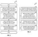
- FIG. 4 shows a design of an apparatus 400 for reporting channel feedback.
- Apparatus 400 includes a module 412 to obtain an initial channel vector for a communication channel from a first station to a second station, a module 414 to select a codebook in a set of codebooks for quantizing the initial channel vector, each codebook including a different set of channel vectors, a module 416 to select a channel vector in the selected codebook based on the initial channel vector, and a module 418 to send the selected channel vector from the second station to the first station.
- FIG. 5 shows a design of a process 500 for performing channel estimation for a communication channel from a first station to a second station.
- Process 500 may be performed by the first station, which may be a base station, a UE, or some other entity.
- the first station e.g., transmitter 110 or 210) may receive a plurality of reported channel vectors (e.g., g ( n ) through g ( n -L-1)) sent by the second station in a plurality of reporting intervals (block 512).
- the plurality of reported channel vectors may be determined by the second station based on a set of codebooks, with each codebook including a different set of channel vectors/codewords.
- the first station may derive a final channel vector (e.g., ⁇ ( n + ⁇ )) for the communication channel based on the plurality of reported channel vectors (block 514).
- each reported channel vector may include channel direction information and may have unit magnitude.
- the first station may remove phase ambiguity in the plurality of reported channel vectors to obtain a plurality of phase corrected channel vectors, e.g., as shown in equation (6).
- the first station may form multiple intermediate channel vectors (e.g., g k ) for multiple transmit antennas at the first station based on the plurality of phase corrected channel vectors, e.g., as shown in equation (7).
- Each intermediate channel vector may include channel gains for one transmit antenna in the plurality of phase corrected channel vectors.
- each reported channel vector may include channel direction and magnitude information.
- the first station may form each intermediate channel vector with channel gains for one transmit antenna in the plurality of reported channel vectors.
- the first station may derive a channel gain for each transmit antenna based on the intermediate channel vector for that transmit antenna.
- the first station may filter the intermediate channel vector for each transmit antenna with an MMSE filter to obtain the channel gain for that transmit antenna, e.g., as shown in equation (11).
- the first station may determine a covariance matrix and a correlation vector for each transmit antenna, e.g., as shown in equations (8) and (9).
- the first station may then determine an MMSE filter for each transmit antenna based on the covariance matrix and the correlation vector for that transmit antenna, e.g., as shown in equation (10).
- the first station may average the intermediate channel vector for each transmit antenna to obtain the channel gain for that transmit antenna.
- the final channel vector may include multiple channel gains for the multiple transmit antennas at the first station.
- the first station may receive one reported channel vector in each reporting interval for a MISO channel from the multiple transmit antennas at the first station to a single receive antenna at the second station.
- the first station may receive multiple reported channel vectors in each reporting interval for a MIMO channel from the multiple transmit antennas at the first station to multiple receive antennas at the second station.
- the first station may receive one reported channel vector for each receive antenna.
- the first station may derive multiple final channel vectors for the multiple receive antennas. Each final channel vector may be for a different receive antenna and may be derived based on the reported channel vectors for that receive antenna.
- the first station may receive one reported channel vector in each reporting interval for the MIMO channel.
- This reported channel vector may be obtained by the second station by concatenating smaller initial channel vectors for the multiple antennas at the second station.
- the first station may derive one final channel vector for the multiple receive antennas and may demultiplex this final channel vector to obtain multiple smaller final channel vectors for the multiple receive antennas.
- FIG. 6 shows a design of an apparatus 600 for performing channel estimation.
- Apparatus 600 includes a module 612 to receive at a first station a plurality of reported channel vectors sent by a second station in a plurality of reporting intervals, the plurality of reported channel vectors being determined by the second station based on a set of codebooks, each codebook including a different set of channel vectors, and a module 612 to derive a final channel vector based on the plurality of reported channel vectors.
- the modules in FIGS. 4 and 6 may comprise processors, electronics devices, hardware devices, electronics components, logical circuits, memories, software codes, firmware codes, etc., or any combination thereof.
- FIG. 7 shows a block diagram of a design of a base station 710 and a UE 750.
- a base station may also be referred to as a Node B, an evolved Node B (eNB), an access point, etc.
- eNB evolved Node B
- a UE may also be referred to as a mobile station, a terminal, an access terminal, a subscriber unit, a station, etc.
- a UE may be a cellular phone, a personal digital assistant (PDA), a wireless modem, a wireless communication device, a handheld device, a laptop computer, a cordless phone, etc.
- PDA personal digital assistant
- base station 710 is equipped with K antennas 734a through 734k
- UE 750 is equipped with R antennas 752a through 752r, where in general K ⁇ 1 and R ⁇ 1.
- a transmit processor 720 may receive data for one or more UEs from a data source 712, process (e.g., encode and modulate) the data for each UE based on one or more modulation and coding schemes for that UE, and provide data symbols for all UEs. Transmit processor 720 may also generate control symbols for control information. Transmit processor 720 may further generate reference/pilot symbols for one or more reference signals.
- a MIMO processor 730 may perform precoding on the data symbols, the control symbols, and/or the reference symbols, if applicable, and may provide K output symbol streams to K modulators (MOD) 732a through 732k. Each modulator 732 may process its output symbol stream (e.g., for OFDM) to obtain an output sample stream.
- Each modulator 732 may further condition (e.g., convert to analog, filter, amplify, and upconvert) its output sample stream and generate a downlink signal.
- K downlink signals from modulators 732a through 732k may be transmitted via antennas 734a through 734k, respectively.
- R antennas 752a through 752r may receive the K downlink signals from base station 710, and each antenna 752 may provide a received signal to an associated demodulator (DEMOD) 754.
- Each demodulator 754 may condition (e.g., filter, amplify, downconvert, and digitize) its received signal to obtain samples and may further process the samples (e.g., for OFDM) to obtain received symbols.
- Each demodulator 754 may provide received data symbols to a MIMO detector 760 and provide received reference symbols to a channel processor 794.
- Channel processor 794 may estimate the response of the downlink channel from base station 710 to UE 750 based on the received reference symbols and may provide a channel estimate to MIMO detector 760.
- MIMO detector 760 may perform MIMO detection on the received data symbols based on the channel estimate and provide symbol estimates, which may be estimates of the transmitted symbols.
- a receive processor 770 may process (e.g., demodulate and decode) the symbol estimates based on the modulation and coding scheme(s) used for UE 750, provide decoded data to a data sink 772, and provide decoded control information to a controller/processor 790.
- UE 750 may estimate the downlink channel response and generate channel feedback information, which may comprise reported channel vectors. UE 750 may also estimate the downlink channel quality and determine channel quality indicator (CQI) information.
- Feedback information e.g., the channel feedback information, CQI information, etc.
- data from a data source 778, and a reference signal may be processed (e.g., encoded and modulated) by a transmit processor 780, precoded by a MIMO processor 782, if applicable, and further processed by modulators 754a through 754r to generate R uplink signals, which may be transmitted via antennas 752a through 752r.
- the R uplink signals from UE 750 may be received by K antennas 734a through 734k and processed by demodulators 732a through 732k.
- a channel processor 744 may estimate the response of the uplink channel from UE 750 to base station 710 and may provide a channel estimate to MIMO detector 736.
- MIMO detector 736 may perform MIMO detection based on the channel estimate and provide symbol estimates.
- a receive processor 738 may process the symbol estimates, provide decoded data to a data sink 739, and provide decoded feedback information to a controller/processor 740. Controller/processor 740 may control data transmission to UE 750 based on the feedback information.
- Controllers/processors 740 and 790 may direct the operation at base station 710 and UE 750, respectively.
- Processor 794, processor 790 and/or other processors and modules at UE 750 may perform or direct process 300 in FIG. 3 , process 500 in FIG. 5 , and/or other processes for the techniques described herein.
- Processor 744, processor 740 and/or other processors and modules at base station 710 may also perform or direct process 300 in FIG. 3 , process 500 in FIG. 5 , and/or other processes for the techniques described herein.
- Memories 742 and 792 may store data and program codes for base station 710 and UE 750, respectively.
- a scheduler 746 may select UE 750 and/or other UEs for data transmission on the downlink and/or uplink based on the feedback information received from the UEs.
- DSP digital signal processor
- ASIC application specific integrated circuit
- FPGA field programmable gate array
- a general-purpose processor may be a microprocessor, but in the alternative, the processor may be any conventional processor, controller, microcontroller, or state machine.
- a processor may also be implemented as a combination of computing devices, e.g., a combination of a DSP and a microprocessor, a plurality of microprocessors, one or more microprocessors in conjunction with a DSP core, or any other such configuration.
- a software module may reside in RAM memory, flash memory, ROM memory, EPROM memory, EEPROM memory, registers, hard disk, a removable disk, a CD-ROM, or any other form of storage medium known in the art.
- An exemplary storage medium is coupled to the processor such that the processor can read information from, and write information to, the storage medium.
- the storage medium may be integral to the processor.
- the processor and the storage medium may reside in an ASIC.
- the ASIC may reside in a user terminal.
- the processor and the storage medium may reside as discrete components in a user terminal.
- the functions described may be implemented in hardware, software, firmware, or any combination thereof. If implemented in software, the functions may be stored on or transmitted over as one or more instructions or code on a computer-readable medium.
- Computer-readable media includes both computer storage media and communication media including any medium that facilitates transfer of a computer program from one place to another.
- a storage media may be any available media that can be accessed by a general purpose or special purpose computer.
- such computer-readable media can comprise RAM, ROM, EEPROM, CD-ROM or other optical disk storage, magnetic disk storage or other magnetic storage devices, or any other medium that can be used to carry or store desired program code means in the form of instructions or data structures and that can be accessed by a general-purpose or special-purpose computer, or a general-purpose or special-purpose processor. Also, any connection is properly termed a computer-readable medium.
- Disk and disc includes compact disc (CD), laser disc, optical disc, digital versatile disc (DVD), floppy disk and blu-ray disc where disks usually reproduce data magnetically, while discs reproduce data optically with lasers. Combinations of the above should also be included within the scope of computer-readable media.
Landscapes
- Engineering & Computer Science (AREA)
- Computer Networks & Wireless Communication (AREA)
- Signal Processing (AREA)
- Physics & Mathematics (AREA)
- Mathematical Physics (AREA)
- Quality & Reliability (AREA)
- Power Engineering (AREA)
- Electromagnetism (AREA)
- Radio Transmission System (AREA)
- Mobile Radio Communication Systems (AREA)
Claims (14)
- Verfahren zum Berichten von Kanalrückmeldungsinformation umfassend:Erhalten (312) eines initialen Kanalvektors für einen Kommunikationskanal von einer ersten Station zu einer zweiten Station, gekennzeichnet durchAuswählen (314) eines Codebuchs in einem Satz von Codebücher zum Quantisieren des initialen Kanalvektors, wobei jedes Codebuch einen anderen Satz von Kanalvektoren beinhaltet, wobei unterschiedliche Codebücher im Satz von Codebücher in unterschiedlichen Berichtsintervallen ausgewählt werden;Auswählen (316) eines Kanalvektors im ausgewählten Codebuch basierend auf dem initialen Kanalvektor; undSenden (318) des ausgewählten Kanalvektors von der zweiten Station an die erste Station.
- Verfahren gemäß Anspruch 1, wobei das Auswählen eines Kanalvektors in dem ausgewählten Codebuch umfasst
Erhalten eines normalisierten Kanalvektors basierend auf dem initialen Kanalvektor, Korrelieren des normalisierten Kanalvektors mit jedem Kanalvektor in dem ausgewählten Codebuch, und
Auswählen eines Kanalvektors mit einem größten Korrelationsergebnis unter allen Kanalvektoren in dem ausgewählten Codebuch. - Verfahren gemäß Anspruch 1, wobei das Auswählen eines Kanalvektors in dem ausgewählten Codebuch umfasst
Bestimmen einer Entfernung zwischen dem initialen Kanalvektor und jedem Kanalvektor im ausgewählten Codebuch, und
Auswählen eines Kanalvektors mit einer geringsten Entfernung unter allen Kanalvektoren im ausgewählten Codebuch. - Verfahren gemäß Anspruch 1, wobei der initiale Kanalvektor für eine Empfangsantenne bei der zweiten Station ist, das Verfahren weiterhin umfassend:Erhalten zumindest eines zusätzlichen initialen Kanalvektors für zumindest eine zusätzliche Empfangsantenne an der zweiten Station;Auswählen zumindest eines Kanalvektors im ausgewählten Codebuch basierend auf dem zumindest einem zusätzlichen initialen Kanalvektor; undSenden aller ausgewählten Kanalvektoren von der zweiten Station an die erste Station.
- Verfahren gemäß Anspruch 1, weiterhin umfassend:Erhalten von mehrerer kürzerer initialer Kanalvektoren für mehrere Empfangsantennen bei der zweiten Station, einen kürzeren initialen Kanalvektor für jede Empfangsantenne; undBilden des initialen Kanalvektors basierend auf den mehreren kürzeren initialen Kanalvektoren.
- Verfahren gemäß Anspruch 1, weiterhin umfassend:Erhalten mehrerer initialer Kanalvektoren für mehrere Empfangsantennen bei der zweiten Station, wobei der initiale Kanalvektor für eine Empfangsantenne ist;Ableiten einer äquivalenten Kanalmatrix basierend auf den mehreren initialen Kanalvektoren und einem besonderen Empfangsraumfilter; undAuswählen zumindest eines Kanalvektors in dem ausgewählten Codebuch basierend auf zumindest einem Vektor in der äquivalenten Kanalmatrix; undSenden des zumindest eines ausgewählten Kanalvektors von der zweiten Station an die erste Station, wobei der ausgewählte Kanalvektor einer aus dem zumindest einen ausgewählten Kanalvektor ist.
- Verfahren gemäß Anspruch 1, wobei jedes Codebuch Kanalvektoren mit unterschiedlichen Richtungen und Einheitsgröße beinhaltet.
- Verfahren gemäß Anspruch 1, wobei jedes Codebuch Kanalvektoren mit unterschiedlichen Richtungen und Größe beinhaltet.
- Vorrichtung zum Berichten von Kanalrückmeldungsinformation aufweisend:Mittel (412) zum Erhalten eines initialen Kanalvektors für einen Kommunikationskanal von einer ersten Station zu einer zweiten Station, wobei die Vorrichtung weiterhin dadurch gekennzeichnet ist, dass sie aufweist:Mittel (414) zum Auswählen eines Codebuchs in einem Satz von Codebücher zum Quantisieren des initialen Kanalvektors, wobei jedes Codebuch einen anderen Satz von Kanalvektoren beinhaltet, wobei unterschiedliche Codebücher im Satz von Codebücher in unterschiedlichen Berichtsintervallen ausgewählt werden;Mittel (416) zum Auswählen eines Kanalvektors in dem ausgewählten Codebuch basieren auf dem initialen Kanalvektor; undMittel (418) zum Senden des ausgewählten Kanalvektors von der zweiten Station an die erste Station.
- Vorrichtung gemäß Anspruch 9, wobei das Mittel zum Auswählen eines Kanalvektors in dem ausgewählten Codebuch aufweist:Mittel zum Erhalten eines normalisierten Kanalvektors basierend auf dem initialen Kanalvektor,Mittel zum Korrelieren des normalisierten Kanalvektors mit jedem Kanalvektor in dem ausgewählten Codebuch, undMittel zum Auswählen eines Kanalvektors mit einem größten Korrelationsergebnis unter allen Kanalvektoren in dem ausgewählten Codebuch.
- Vorrichtung gemäß Anspruch 9, wobei das Mittel zum Auswählen eines Kanalvektors in dem ausgewählten Codebuch aufweist
Mittel zum Bestimmen einer Entfernung zwischen dem initialen Kanalvektor und jedem Kanalvektor im ausgewählten Codebuch, und
Mittel zum Auswählen eines Kanalvektors mit einer geringsten Entfernung unter allen Kanalvektoren im ausgewählten Codebuch. - Vorrichtung gemäß Anspruch 9, wobei der initiale Kanalvektor für eine Empfangsantenne bei der zweiten Station ist, die Vorrichtung weiterhin aufweisend:Mittel zum Erhalten zumindest eines zusätzlichen initialen Kanalvektors für zumindest eine zusätzliche Empfangsantenne an der zweiten Station;Mittel zum Auswählen zumindest eines Kanalvektors im ausgewählten Codebuch basierend auf dem zumindest einem zusätzlichen initialen Kanalvektor; undMittel zum Senden aller ausgewählten Kanalvektoren von der zweiten Station an die erste Station.
- Vorrichtung gemäß Anspruch 9, weiterhin aufweisend:Mittel zum Erhalten von mehrerer kürzerer initialer Kanalvektoren für mehrere Empfangsantennen bei der zweiten Station, einen kürzeren initialen Kanalvektor für jede Empfangsantenne; undMittel zum Bilden des initialen Kanalvektors basierend auf den mehreren kürzeren initialen Kanalvektoren.
- Computerprogram aufweisend ausführbare Anweisungen zum Veranlassen zumindest eines Computers um ein Verfahren nach einem der Ansprüche 1 bis 8 durchzuführen, wenn das Computerprogramm ausgeführt wird.
Priority Applications (1)
| Application Number | Priority Date | Filing Date | Title |
|---|---|---|---|
| EP13164472.6A EP2618530B1 (de) | 2009-01-06 | 2009-11-29 | Verfahren und Vorrichtung zur Kanalschätzung mithilfe mehrerer Beschreibungscodes |
Applications Claiming Priority (3)
| Application Number | Priority Date | Filing Date | Title |
|---|---|---|---|
| US14282609P | 2009-01-06 | 2009-01-06 | |
| US12/620,141 US8787183B2 (en) | 2009-01-06 | 2009-11-17 | Method and apparatus for channel estimation using multiple description codes |
| PCT/US2009/066031 WO2010080231A1 (en) | 2009-01-06 | 2009-11-29 | Method and apparatus for channel estimation using multiple description codes |
Related Child Applications (2)
| Application Number | Title | Priority Date | Filing Date |
|---|---|---|---|
| EP13164472.6A Division-Into EP2618530B1 (de) | 2009-01-06 | 2009-11-29 | Verfahren und Vorrichtung zur Kanalschätzung mithilfe mehrerer Beschreibungscodes |
| EP13164472.6A Division EP2618530B1 (de) | 2009-01-06 | 2009-11-29 | Verfahren und Vorrichtung zur Kanalschätzung mithilfe mehrerer Beschreibungscodes |
Publications (2)
| Publication Number | Publication Date |
|---|---|
| EP2386162A1 EP2386162A1 (de) | 2011-11-16 |
| EP2386162B1 true EP2386162B1 (de) | 2016-09-21 |
Family
ID=42311637
Family Applications (2)
| Application Number | Title | Priority Date | Filing Date |
|---|---|---|---|
| EP09760444.1A Active EP2386162B1 (de) | 2009-01-06 | 2009-11-29 | Verfahren und vorrichtung zur kanalschätzung unter verwendung von mehreren beschreibungscodes |
| EP13164472.6A Active EP2618530B1 (de) | 2009-01-06 | 2009-11-29 | Verfahren und Vorrichtung zur Kanalschätzung mithilfe mehrerer Beschreibungscodes |
Family Applications After (1)
| Application Number | Title | Priority Date | Filing Date |
|---|---|---|---|
| EP13164472.6A Active EP2618530B1 (de) | 2009-01-06 | 2009-11-29 | Verfahren und Vorrichtung zur Kanalschätzung mithilfe mehrerer Beschreibungscodes |
Country Status (8)
| Country | Link |
|---|---|
| US (1) | US8787183B2 (de) |
| EP (2) | EP2386162B1 (de) |
| JP (2) | JP5579745B2 (de) |
| KR (2) | KR101490209B1 (de) |
| CN (1) | CN102273154B (de) |
| BR (1) | BRPI0924222B1 (de) |
| TW (1) | TWI431987B (de) |
| WO (1) | WO2010080231A1 (de) |
Families Citing this family (22)
| Publication number | Priority date | Publication date | Assignee | Title |
|---|---|---|---|---|
| US8644408B2 (en) | 2008-10-10 | 2014-02-04 | Qualcomm Incorporated | Method and apparatus for channel feedback in a wireless communication system |
| KR101678435B1 (ko) * | 2009-07-17 | 2016-12-06 | 엘지전자 주식회사 | 다중 안테나 무선 통신 시스템에서 하향링크 신호를 수신하는 방법 및 이를 위한 장치 |
| WO2011021861A2 (en) * | 2009-08-19 | 2011-02-24 | Lg Electronics Inc. | Apparatus and method for generating codebook in wireless communication system |
| KR101092686B1 (ko) * | 2010-01-08 | 2011-12-09 | 서울대학교산학협력단 | 직교 주파수 분할 다중 접속 기반 다중안테나 무선 시스템에서 송신 빔포밍 방법 및 장치 |
| US8711963B2 (en) * | 2010-02-11 | 2014-04-29 | Samsung Electronics Co., Ltd. | Unified feedback frame for supporting a plurality of feedback modes and a multiple-input multiple-output (MIMO) communication system using the unified feedback frame |
| JP5723457B2 (ja) * | 2011-03-16 | 2015-05-27 | エヌイーシー(チャイナ)カンパニー, リミテッドNEC(China)Co.,Ltd. | ビームフォーミング方法および受信機 |
| KR101680212B1 (ko) * | 2011-07-18 | 2016-11-28 | 주식회사 케이티 | 단말의 채널 상태 정보 전송 방법, 그 단말, 전송단의 채널 상태 정보 수신 방법, 및 그 전송단 |
| EP2592764B1 (de) * | 2011-11-14 | 2014-03-19 | Alcatel Lucent | Verfahren zur Optimierung der Funkverbindungsübertragung in einem Funkkommunikationssystem, Übertragungseinheit, Auswahleinheit, Netzwerkknoten und Vorrichtung dafür |
| CN103731233B (zh) * | 2012-10-12 | 2018-07-03 | 华为技术有限公司 | 码字反馈方法及接收机 |
| WO2015047428A1 (en) * | 2013-09-27 | 2015-04-02 | Intel Corporation | Channel-adaptive configurable mimo detector for multi-mode wireless systems |
| KR102220399B1 (ko) * | 2013-10-21 | 2021-02-25 | 삼성전자주식회사 | 다중 입력 다중 출력 방식을 사용하는 무선 통신 시스템에서 사용자 단말기 선택 및 빔 포밍 동작 수행 장치 및 방법 |
| US10601480B2 (en) | 2014-06-10 | 2020-03-24 | Telefonaktiebolaget Lm Ericsson (Publ) | Systems and methods for adaptively restricting CSI reporting in multi antenna wireless communications systems utilizing unused bit resources |
| US9602178B2 (en) * | 2014-06-23 | 2017-03-21 | Nokia Technologies Oy | Joint precoder and receiver design for MU-MIMO downlink |
| CN105207758B (zh) * | 2014-06-27 | 2018-09-07 | 上海诺基亚贝尔股份有限公司 | 一种用于选择下行链路的方法、装置与设备 |
| US10498405B2 (en) * | 2014-10-29 | 2019-12-03 | Telefonaktiebolaget L M Ericsson (Publ) | Codebook restriction |
| KR101955102B1 (ko) * | 2017-07-27 | 2019-03-06 | 포항공과대학교 산학협력단 | 다중 안테나 통신 시스템에서 코드북 기반 수신 신호 입사 각도 추정 방법 및 그 장치 |
| WO2019099024A1 (en) * | 2017-11-17 | 2019-05-23 | Nokia Technologies Oy | Methods and apparatuses for multi quantization codebook for explicit channel state information feedback in new radio |
| WO2020112840A1 (en) | 2018-11-27 | 2020-06-04 | XCOM Labs, Inc. | Non-coherent cooperative multiple-input multiple-output communications |
| CN111628807A (zh) * | 2019-02-28 | 2020-09-04 | 英国电讯有限公司 | Mimo系统中的信道估计 |
| CN110753241B (zh) * | 2019-10-21 | 2021-10-19 | 山东师范大学 | 基于多描述网络的图像编码、解码方法及系统 |
| CN115699605A (zh) | 2020-05-26 | 2023-02-03 | 艾斯康实验室公司 | 干扰感知波束成形 |
| WO2022093988A1 (en) | 2020-10-30 | 2022-05-05 | XCOM Labs, Inc. | Clustering and/or rate selection in multiple-input multiple-output communication systems |
Citations (1)
| Publication number | Priority date | Publication date | Assignee | Title |
|---|---|---|---|---|
| US20080232503A1 (en) * | 2007-03-22 | 2008-09-25 | Kyungho Kim | Variable codebook for mimo system |
Family Cites Families (21)
| Publication number | Priority date | Publication date | Assignee | Title |
|---|---|---|---|---|
| US6904404B1 (en) * | 1996-07-01 | 2005-06-07 | Matsushita Electric Industrial Co., Ltd. | Multistage inverse quantization having the plurality of frequency bands |
| WO2005002162A1 (en) | 2003-06-30 | 2005-01-06 | International Business Machines Corporation | Vector equalizer and vector sequence estimator for block-coded modulation schemes |
| US8385433B2 (en) | 2005-10-27 | 2013-02-26 | Qualcomm Incorporated | Linear precoding for spatially correlated channels |
| TW201025894A (en) * | 2006-02-10 | 2010-07-01 | Interdigital Tech Corp | Method and apparatus for performing uplink transmission in a multiple-input multiple-output single carrier frequency division multiple access system |
| US7894820B2 (en) | 2006-05-01 | 2011-02-22 | Intel Corporation | Channel feedback using channel state predictions based also on delays |
| AU2007284477B2 (en) | 2006-08-17 | 2012-02-02 | Apple Inc. | Method and apparatus for providing efficient precoding feedback in a MIMO wireless communication system |
| US8626104B2 (en) | 2006-09-28 | 2014-01-07 | Apple Inc. | Generalized codebook design method for limited feedback systems |
| CN101166052B (zh) | 2006-10-19 | 2012-05-23 | 株式会社Ntt都科摩 | 一种多输入多输出系统的预编码方法及使用该方法的设备 |
| JP4848246B2 (ja) | 2006-10-26 | 2011-12-28 | フランスベッド株式会社 | ソファー |
| US8218667B2 (en) * | 2006-11-15 | 2012-07-10 | Lg Electronics Inc. | Data transmission method using dirty paper coding in MIMO system |
| US20080130764A1 (en) | 2006-12-04 | 2008-06-05 | Samsung Electronics Co., Ltd. | System and method for wireless communication of uncompressed high definition video data using beamforming vector feedback based on hybrid quantization |
| CN101291526B (zh) | 2007-04-18 | 2012-10-17 | 松下电器产业株式会社 | 减少信息反馈量的自适应调度方法和装置 |
| KR101197378B1 (ko) | 2007-04-30 | 2012-11-05 | 인터디지탈 테크날러지 코포레이션 | Mimo 무선 통신 시스템에서의 에러 검출 및 검사의 피드백 시그널링 |
| US20080268785A1 (en) | 2007-04-30 | 2008-10-30 | Mccoy James W | UE-autonomous CFI reporting |
| US7769098B2 (en) | 2007-06-05 | 2010-08-03 | Texas Instruments Incorporated | Low complexity precoding matrix selection |
| US20080304552A1 (en) | 2007-06-05 | 2008-12-11 | Chandrashekhar Thejaswi Pataguppe | Receiver for communication system |
| US8374275B2 (en) * | 2007-06-23 | 2013-02-12 | Panasonic Corporation | Method and system for communication channel optimization in a multiple-input multiple-output (MIMO) communication system |
| US8055192B2 (en) * | 2007-06-25 | 2011-11-08 | Samsung Electronics Co., Ltd. | Method of feeding back channel information and receiver for feeding back channel information |
| US8098755B2 (en) * | 2007-09-07 | 2012-01-17 | Broadcom Corporation | Method and system for beamforming in a multiple user multiple input multiple output (MIMO) communication system using a codebook |
| WO2009090618A2 (en) | 2008-01-17 | 2009-07-23 | Nxp B.V. | Method and system for managing precoding in a multi-user wireless communication system |
| CN101304300B (zh) | 2008-05-29 | 2010-12-08 | 上海交通大学 | 基于有限反馈的多用户mimo系统信道量化方法和装置 |
-
2009
- 2009-11-17 US US12/620,141 patent/US8787183B2/en active Active
- 2009-11-26 TW TW098140439A patent/TWI431987B/zh not_active IP Right Cessation
- 2009-11-29 WO PCT/US2009/066031 patent/WO2010080231A1/en active Application Filing
- 2009-11-29 EP EP09760444.1A patent/EP2386162B1/de active Active
- 2009-11-29 EP EP13164472.6A patent/EP2618530B1/de active Active
- 2009-11-29 CN CN200980153956.2A patent/CN102273154B/zh active Active
- 2009-11-29 KR KR1020137022912A patent/KR101490209B1/ko active IP Right Grant
- 2009-11-29 KR KR1020117018374A patent/KR20110102505A/ko not_active Application Discontinuation
- 2009-11-29 JP JP2011545352A patent/JP5579745B2/ja not_active Expired - Fee Related
- 2009-11-29 BR BRPI0924222-8A patent/BRPI0924222B1/pt not_active IP Right Cessation
-
2014
- 2014-05-02 JP JP2014095466A patent/JP2014195268A/ja active Pending
Patent Citations (1)
| Publication number | Priority date | Publication date | Assignee | Title |
|---|---|---|---|---|
| US20080232503A1 (en) * | 2007-03-22 | 2008-09-25 | Kyungho Kim | Variable codebook for mimo system |
Non-Patent Citations (2)
| Title |
|---|
| NTT DOCOMO: "Multi-Codebook Pre-coding Scheme for MIMO in E-UTRA Downlink", 3GPP DRAFT; R1-070856 MULTI-CB PRECODING, vol. RAN WG1, 6 February 2007 (2007-02-06), ST. LOUIS, USA, XP050104872 * |
| TEXAS INSTRUMENTS: "Precoding Codebook Design For 4 Node-B Antenna", 3GPP DRAFT; R1-070730 TI CODEBOOK 4 ANTS, vol. RAN WG1, 6 February 2007 (2007-02-06), ST. LOUIS, USA, XP050104760 * |
Also Published As
| Publication number | Publication date |
|---|---|
| CN102273154B (zh) | 2015-04-15 |
| EP2386162A1 (de) | 2011-11-16 |
| KR20130113523A (ko) | 2013-10-15 |
| KR20110102505A (ko) | 2011-09-16 |
| US20100172256A1 (en) | 2010-07-08 |
| JP5579745B2 (ja) | 2014-08-27 |
| JP2012514937A (ja) | 2012-06-28 |
| TW201108676A (en) | 2011-03-01 |
| JP2014195268A (ja) | 2014-10-09 |
| EP2618530B1 (de) | 2018-03-14 |
| US8787183B2 (en) | 2014-07-22 |
| KR101490209B1 (ko) | 2015-02-05 |
| CN102273154A (zh) | 2011-12-07 |
| WO2010080231A1 (en) | 2010-07-15 |
| TWI431987B (zh) | 2014-03-21 |
| EP2618530A1 (de) | 2013-07-24 |
| BRPI0924222A2 (pt) | 2018-05-22 |
| BRPI0924222B1 (pt) | 2021-01-12 |
Similar Documents
| Publication | Publication Date | Title |
|---|---|---|
| EP2386162B1 (de) | Verfahren und vorrichtung zur kanalschätzung unter verwendung von mehreren beschreibungscodes | |
| JP5745017B2 (ja) | ワイヤレス通信ネットワーク中の複数ユーザのmimoのためのスケジューリング | |
| EP2327167B1 (de) | Verfahren und vorrichtung zum unterstützen von verteiltem mimo in einem drahtlosen kommunikationssystem | |
| EP2183892B1 (de) | Mimo-übertragung mit räumlicher vorcodierung | |
| EP2179517B1 (de) | Verfahren und vorrichtung zur datenübertragung in einem mimo kommunikationssystem | |
| EP2665200B1 (de) | Meldung von Kanalinformationen zur Unterstützung von koordinierter Mehrpunkt-Datenübertragung | |
| US8509710B2 (en) | MIMO transmission with explicit and implicit cyclic delays | |
| KR20080113946A (ko) | 무선통신시스템에서 간섭 제거 장치 및 방법 | |
| EP2309659A1 (de) | Verfahren zur Berechnung eines Kanalqualitätsindikators (CQI) in einem räumlich gemultiplexten, drahtlosen MIMO-Kommunikationssystem unter Verwendung nichtlinearer Erfassung | |
| KR20160010724A (ko) | 다운링크를 위한 다중-사용자 mimo 시스템 및 그 방법 |
Legal Events
| Date | Code | Title | Description |
|---|---|---|---|
| PUAI | Public reference made under article 153(3) epc to a published international application that has entered the european phase |
Free format text: ORIGINAL CODE: 0009012 |
|
| 17P | Request for examination filed |
Effective date: 20110803 |
|
| AK | Designated contracting states |
Kind code of ref document: A1 Designated state(s): AT BE BG CH CY CZ DE DK EE ES FI FR GB GR HR HU IE IS IT LI LT LU LV MC MK MT NL NO PL PT RO SE SI SK SM TR |
|
| DAX | Request for extension of the european patent (deleted) | ||
| 17Q | First examination report despatched |
Effective date: 20130527 |
|
| GRAP | Despatch of communication of intention to grant a patent |
Free format text: ORIGINAL CODE: EPIDOSNIGR1 |
|
| INTG | Intention to grant announced |
Effective date: 20160330 |
|
| GRAS | Grant fee paid |
Free format text: ORIGINAL CODE: EPIDOSNIGR3 |
|
| GRAA | (expected) grant |
Free format text: ORIGINAL CODE: 0009210 |
|
| AK | Designated contracting states |
Kind code of ref document: B1 Designated state(s): AT BE BG CH CY CZ DE DK EE ES FI FR GB GR HR HU IE IS IT LI LT LU LV MC MK MT NL NO PL PT RO SE SI SK SM TR |
|
| REG | Reference to a national code |
Ref country code: GB Ref legal event code: FG4D |
|
| REG | Reference to a national code |
Ref country code: CH Ref legal event code: EP |
|
| REG | Reference to a national code |
Ref country code: AT Ref legal event code: REF Ref document number: 831826 Country of ref document: AT Kind code of ref document: T Effective date: 20161015 |
|
| REG | Reference to a national code |
Ref country code: IE Ref legal event code: FG4D |
|
| REG | Reference to a national code |
Ref country code: DE Ref legal event code: R096 Ref document number: 602009041280 Country of ref document: DE |
|
| REG | Reference to a national code |
Ref country code: FR Ref legal event code: PLFP Year of fee payment: 8 |
|
| REG | Reference to a national code |
Ref country code: LT Ref legal event code: MG4D Ref country code: NL Ref legal event code: MP Effective date: 20160921 |
|
| PG25 | Lapsed in a contracting state [announced via postgrant information from national office to epo] |
Ref country code: FI Free format text: LAPSE BECAUSE OF FAILURE TO SUBMIT A TRANSLATION OF THE DESCRIPTION OR TO PAY THE FEE WITHIN THE PRESCRIBED TIME-LIMIT Effective date: 20160921 Ref country code: LT Free format text: LAPSE BECAUSE OF FAILURE TO SUBMIT A TRANSLATION OF THE DESCRIPTION OR TO PAY THE FEE WITHIN THE PRESCRIBED TIME-LIMIT Effective date: 20160921 Ref country code: NO Free format text: LAPSE BECAUSE OF FAILURE TO SUBMIT A TRANSLATION OF THE DESCRIPTION OR TO PAY THE FEE WITHIN THE PRESCRIBED TIME-LIMIT Effective date: 20161221 |
|
| REG | Reference to a national code |
Ref country code: AT Ref legal event code: MK05 Ref document number: 831826 Country of ref document: AT Kind code of ref document: T Effective date: 20160921 |
|
| PG25 | Lapsed in a contracting state [announced via postgrant information from national office to epo] |
Ref country code: SE Free format text: LAPSE BECAUSE OF FAILURE TO SUBMIT A TRANSLATION OF THE DESCRIPTION OR TO PAY THE FEE WITHIN THE PRESCRIBED TIME-LIMIT Effective date: 20160921 Ref country code: NL Free format text: LAPSE BECAUSE OF FAILURE TO SUBMIT A TRANSLATION OF THE DESCRIPTION OR TO PAY THE FEE WITHIN THE PRESCRIBED TIME-LIMIT Effective date: 20160921 Ref country code: BE Free format text: LAPSE BECAUSE OF NON-PAYMENT OF DUE FEES Effective date: 20161130 Ref country code: GR Free format text: LAPSE BECAUSE OF FAILURE TO SUBMIT A TRANSLATION OF THE DESCRIPTION OR TO PAY THE FEE WITHIN THE PRESCRIBED TIME-LIMIT Effective date: 20161222 Ref country code: LV Free format text: LAPSE BECAUSE OF FAILURE TO SUBMIT A TRANSLATION OF THE DESCRIPTION OR TO PAY THE FEE WITHIN THE PRESCRIBED TIME-LIMIT Effective date: 20160921 |
|
| PG25 | Lapsed in a contracting state [announced via postgrant information from national office to epo] |
Ref country code: RO Free format text: LAPSE BECAUSE OF FAILURE TO SUBMIT A TRANSLATION OF THE DESCRIPTION OR TO PAY THE FEE WITHIN THE PRESCRIBED TIME-LIMIT Effective date: 20160921 Ref country code: EE Free format text: LAPSE BECAUSE OF FAILURE TO SUBMIT A TRANSLATION OF THE DESCRIPTION OR TO PAY THE FEE WITHIN THE PRESCRIBED TIME-LIMIT Effective date: 20160921 |
|
| PG25 | Lapsed in a contracting state [announced via postgrant information from national office to epo] |
Ref country code: CZ Free format text: LAPSE BECAUSE OF FAILURE TO SUBMIT A TRANSLATION OF THE DESCRIPTION OR TO PAY THE FEE WITHIN THE PRESCRIBED TIME-LIMIT Effective date: 20160921 Ref country code: BE Free format text: LAPSE BECAUSE OF FAILURE TO SUBMIT A TRANSLATION OF THE DESCRIPTION OR TO PAY THE FEE WITHIN THE PRESCRIBED TIME-LIMIT Effective date: 20160921 Ref country code: AT Free format text: LAPSE BECAUSE OF FAILURE TO SUBMIT A TRANSLATION OF THE DESCRIPTION OR TO PAY THE FEE WITHIN THE PRESCRIBED TIME-LIMIT Effective date: 20160921 Ref country code: PL Free format text: LAPSE BECAUSE OF FAILURE TO SUBMIT A TRANSLATION OF THE DESCRIPTION OR TO PAY THE FEE WITHIN THE PRESCRIBED TIME-LIMIT Effective date: 20160921 Ref country code: BG Free format text: LAPSE BECAUSE OF FAILURE TO SUBMIT A TRANSLATION OF THE DESCRIPTION OR TO PAY THE FEE WITHIN THE PRESCRIBED TIME-LIMIT Effective date: 20161221 Ref country code: SK Free format text: LAPSE BECAUSE OF FAILURE TO SUBMIT A TRANSLATION OF THE DESCRIPTION OR TO PAY THE FEE WITHIN THE PRESCRIBED TIME-LIMIT Effective date: 20160921 Ref country code: ES Free format text: LAPSE BECAUSE OF FAILURE TO SUBMIT A TRANSLATION OF THE DESCRIPTION OR TO PAY THE FEE WITHIN THE PRESCRIBED TIME-LIMIT Effective date: 20160921 Ref country code: SM Free format text: LAPSE BECAUSE OF FAILURE TO SUBMIT A TRANSLATION OF THE DESCRIPTION OR TO PAY THE FEE WITHIN THE PRESCRIBED TIME-LIMIT Effective date: 20160921 Ref country code: PT Free format text: LAPSE BECAUSE OF FAILURE TO SUBMIT A TRANSLATION OF THE DESCRIPTION OR TO PAY THE FEE WITHIN THE PRESCRIBED TIME-LIMIT Effective date: 20170123 Ref country code: IS Free format text: LAPSE BECAUSE OF FAILURE TO SUBMIT A TRANSLATION OF THE DESCRIPTION OR TO PAY THE FEE WITHIN THE PRESCRIBED TIME-LIMIT Effective date: 20170121 |
|
| REG | Reference to a national code |
Ref country code: DE Ref legal event code: R097 Ref document number: 602009041280 Country of ref document: DE |
|
| PG25 | Lapsed in a contracting state [announced via postgrant information from national office to epo] |
Ref country code: IT Free format text: LAPSE BECAUSE OF FAILURE TO SUBMIT A TRANSLATION OF THE DESCRIPTION OR TO PAY THE FEE WITHIN THE PRESCRIBED TIME-LIMIT Effective date: 20160921 |
|
| REG | Reference to a national code |
Ref country code: CH Ref legal event code: PL |
|
| PLBE | No opposition filed within time limit |
Free format text: ORIGINAL CODE: 0009261 |
|
| STAA | Information on the status of an ep patent application or granted ep patent |
Free format text: STATUS: NO OPPOSITION FILED WITHIN TIME LIMIT |
|
| PG25 | Lapsed in a contracting state [announced via postgrant information from national office to epo] |
Ref country code: CH Free format text: LAPSE BECAUSE OF NON-PAYMENT OF DUE FEES Effective date: 20161130 Ref country code: DK Free format text: LAPSE BECAUSE OF FAILURE TO SUBMIT A TRANSLATION OF THE DESCRIPTION OR TO PAY THE FEE WITHIN THE PRESCRIBED TIME-LIMIT Effective date: 20160921 Ref country code: LI Free format text: LAPSE BECAUSE OF NON-PAYMENT OF DUE FEES Effective date: 20161130 |
|
| REG | Reference to a national code |
Ref country code: IE Ref legal event code: MM4A |
|
| 26N | No opposition filed |
Effective date: 20170622 |
|
| PG25 | Lapsed in a contracting state [announced via postgrant information from national office to epo] |
Ref country code: LU Free format text: LAPSE BECAUSE OF NON-PAYMENT OF DUE FEES Effective date: 20161130 |
|
| REG | Reference to a national code |
Ref country code: FR Ref legal event code: PLFP Year of fee payment: 9 |
|
| PG25 | Lapsed in a contracting state [announced via postgrant information from national office to epo] |
Ref country code: IE Free format text: LAPSE BECAUSE OF NON-PAYMENT OF DUE FEES Effective date: 20161129 Ref country code: SI Free format text: LAPSE BECAUSE OF FAILURE TO SUBMIT A TRANSLATION OF THE DESCRIPTION OR TO PAY THE FEE WITHIN THE PRESCRIBED TIME-LIMIT Effective date: 20160921 |
|
| PG25 | Lapsed in a contracting state [announced via postgrant information from national office to epo] |
Ref country code: CY Free format text: LAPSE BECAUSE OF FAILURE TO SUBMIT A TRANSLATION OF THE DESCRIPTION OR TO PAY THE FEE WITHIN THE PRESCRIBED TIME-LIMIT Effective date: 20160921 Ref country code: HU Free format text: LAPSE BECAUSE OF FAILURE TO SUBMIT A TRANSLATION OF THE DESCRIPTION OR TO PAY THE FEE WITHIN THE PRESCRIBED TIME-LIMIT; INVALID AB INITIO Effective date: 20091129 |
|
| PG25 | Lapsed in a contracting state [announced via postgrant information from national office to epo] |
Ref country code: MC Free format text: LAPSE BECAUSE OF FAILURE TO SUBMIT A TRANSLATION OF THE DESCRIPTION OR TO PAY THE FEE WITHIN THE PRESCRIBED TIME-LIMIT Effective date: 20160921 Ref country code: HR Free format text: LAPSE BECAUSE OF FAILURE TO SUBMIT A TRANSLATION OF THE DESCRIPTION OR TO PAY THE FEE WITHIN THE PRESCRIBED TIME-LIMIT Effective date: 20160921 Ref country code: MK Free format text: LAPSE BECAUSE OF FAILURE TO SUBMIT A TRANSLATION OF THE DESCRIPTION OR TO PAY THE FEE WITHIN THE PRESCRIBED TIME-LIMIT Effective date: 20160921 Ref country code: TR Free format text: LAPSE BECAUSE OF FAILURE TO SUBMIT A TRANSLATION OF THE DESCRIPTION OR TO PAY THE FEE WITHIN THE PRESCRIBED TIME-LIMIT Effective date: 20160921 |
|
| PG25 | Lapsed in a contracting state [announced via postgrant information from national office to epo] |
Ref country code: MT Free format text: LAPSE BECAUSE OF NON-PAYMENT OF DUE FEES Effective date: 20161129 |
|
| REG | Reference to a national code |
Ref country code: FR Ref legal event code: PLFP Year of fee payment: 10 |
|
| PGFP | Annual fee paid to national office [announced via postgrant information from national office to epo] |
Ref country code: GB Payment date: 20231013 Year of fee payment: 15 |
|
| PGFP | Annual fee paid to national office [announced via postgrant information from national office to epo] |
Ref country code: FR Payment date: 20231010 Year of fee payment: 15 Ref country code: DE Payment date: 20231010 Year of fee payment: 15 |