EP2385641B1 - Verfahren zur Taktsynchronisierung in einem Kommunikationsnetzwerk - Google Patents
Verfahren zur Taktsynchronisierung in einem Kommunikationsnetzwerk Download PDFInfo
- Publication number
- EP2385641B1 EP2385641B1 EP11006429A EP11006429A EP2385641B1 EP 2385641 B1 EP2385641 B1 EP 2385641B1 EP 11006429 A EP11006429 A EP 11006429A EP 11006429 A EP11006429 A EP 11006429A EP 2385641 B1 EP2385641 B1 EP 2385641B1
- Authority
- EP
- European Patent Office
- Prior art keywords
- slave
- node
- synchronization
- master
- nodes
- Prior art date
- Legal status (The legal status is an assumption and is not a legal conclusion. Google has not performed a legal analysis and makes no representation as to the accuracy of the status listed.)
- Not-in-force
Links
Images


Classifications
-
- H—ELECTRICITY
- H04—ELECTRIC COMMUNICATION TECHNIQUE
- H04J—MULTIPLEX COMMUNICATION
- H04J3/00—Time-division multiplex systems
- H04J3/02—Details
- H04J3/06—Synchronising arrangements
- H04J3/0635—Clock or time synchronisation in a network
- H04J3/0638—Clock or time synchronisation among nodes; Internode synchronisation
- H04J3/0658—Clock or time synchronisation among packet nodes
- H04J3/0673—Clock or time synchronisation among packet nodes using intermediate nodes, e.g. modification of a received timestamp before further transmission to the next packet node, e.g. including internal delay time or residence time into the packet
-
- H—ELECTRICITY
- H04—ELECTRIC COMMUNICATION TECHNIQUE
- H04J—MULTIPLEX COMMUNICATION
- H04J3/00—Time-division multiplex systems
- H04J3/02—Details
- H04J3/06—Synchronising arrangements
- H04J3/0635—Clock or time synchronisation in a network
- H04J3/0638—Clock or time synchronisation among nodes; Internode synchronisation
- H04J3/0658—Clock or time synchronisation among packet nodes
- H04J3/0661—Clock or time synchronisation among packet nodes using timestamps
- H04J3/0664—Clock or time synchronisation among packet nodes using timestamps unidirectional timestamps
-
- H—ELECTRICITY
- H04—ELECTRIC COMMUNICATION TECHNIQUE
- H04J—MULTIPLEX COMMUNICATION
- H04J3/00—Time-division multiplex systems
- H04J3/02—Details
- H04J3/06—Synchronising arrangements
- H04J3/0635—Clock or time synchronisation in a network
- H04J3/0638—Clock or time synchronisation among nodes; Internode synchronisation
- H04J3/0658—Clock or time synchronisation among packet nodes
- H04J3/0661—Clock or time synchronisation among packet nodes using timestamps
- H04J3/0667—Bidirectional timestamps, e.g. NTP or PTP for compensation of clock drift and for compensation of propagation delays
Definitions
- the invention refers to a method for clock synchronization in a communication network as well as to a corresponding communication network.
- the nodes in the communication network comprise corresponding clocks which are synchronized with a master clock of a so-called master node.
- the nodes having the clocks being synchronized with the master clock are usually designated as slave nodes.
- a known protocol for performing clock synchronization is the precision time protocol specified in the standard IEEE 1588.
- the synchronization of this protocol is based on exchanging appropriate time information by the use of synchronization messages where the time information is generated by time stamping according to the local clocks in the corresponding nodes.
- the synchronization messages are sequentially transmitted from one node to another node, i.e. starting from the master node to the slave node and from the slave node to the next slave node and so on until each slave node in the network has received a synchronization message.
- the first synchronization message sent by the master node contains a time stamp of a master counter value based on the master clock when the message is transmitted.
- the following slave nodes process this information and send it further.
- each slave node Based on the processing of a slave, all the estimated delays between the transmission time of the previous node and its own current transmission is added to the content of the synchronization message received by the slave node. Based on the information in the synchronization messages, each slave node can synchronize the slave counter values of its slave clock with the master counter values as indicated in the received synchronization messages.
- the method of the invention is performed in a communication network comprising a plurality of nodes, wherein the nodes comprise a master node and slave nodes, wherein the master node has a master clock generating master counter values based on a master counter with a master frequency and wherein each slave node has a slave clock generating slave counter values based on a slave counter with the corresponding slave frequency.
- clock synchronization is performed in successive synchronization cycles.
- synchronization messages are transmitted in a sequence of synchronization messages from the master node to a slave node and from one slave node to another slave node, wherein a synchronization message sent from one node to another node includes information based on one or more measured counter values (i.e. master or slave counter values) of the node sending the synchronization message.
- the master counter value for a measured slave counter value is estimated based on measured counter values by using a state estimation method applied to a probabilistic model for state variables of the nodes. After having estimated the master counter value, this value is used for synchronizing the corresponding slave clock.
- the probabilistic model includes a state transition model as well as an observation model.
- the state transmission model describes the dependency of state variables of slave nodes in a synchronization cycle on state variables of slave nodes in the previous synchronization cycle.
- the observation model describes the dependency of known variables of master and slave nodes on state variables of slave nodes, particularly at the time of receiving a synchronization message.
- known variables refer to variables which are measured or determined with a certain accuracy in a separate process.
- the estimation method is based on the so-called sum-product algorithm which is per se known from the prior art. This sum-product algorithm is applied to a factor graph describing the relationships between known variables and the state variables based on message flows.
- the invention is based on the finding that an appropriate probabilistic representation for modelling the behaviours of the nodes can be defined, thus enabling a good estimation of the master counter value used for synchronization.
- the inventors performed simulations and could show that the synchronization error is very low when the method of the invention is used for clock synchronization.
- a synchronization message sent from the master node includes the measured master counter value when the synchronization message is sent from the master node.
- the content of the other synchronization messages sent from one slave node to another slave node depend on the type of estimation method used according to the invention.
- a synchronization message sent from a slave node includes an approximate master counter value when the synchronization message is sent from the slave node, said approximate master counter value being derived from measured slave counter values of the slave node and from information received in synchronization messages. This form of synchronization message is preferably used in case that the Kalman filter mentioned below is used as the estimation method.
- a synchronization message sent from a slave node includes the measured bridge delay between receiving the previous synchronization message and sending the synchronization message as well as the estimated master counter value for this slave node.
- This kind of synchronization message is preferably used when the estimation method is based on the sum-product algorithm described below.
- the probabilistic model incorporates measurement errors with respect to measured counter values as well as variations of the frequency ratio between the master clock and each slave clock.
- the state variables comprise the master counter value and the frequency ratio between the master frequency and a slave frequency when the synchronization message is received in a slave clock.
- the known state variables used in the observation model comprise a separately estimated line delay (i.e. a line delay being determined with a certain accuracy in a separate line estimation process) in slave counter values between receiving successive synchronization messages in a slave node, a measured bridge delay in slave counter values between receiving a synchronization message and sending the next synchronization message in a slave node and the measured master counter value when the master node sends a synchronization message.
- a separately estimated line delay i.e. a line delay being determined with a certain accuracy in a separate line estimation process
- n refers to the nth slave node receiving a synchronization message in the sequence of synchronization messages
- k refers to the kth synchronization cycle
- TS ( M ( k )) refers to the measured master counter value when the master node sends the synchronization message in the kth synchronization cycle
- x n in k refers to the master counter value at the time of receiving the synchronization message in the nth slave node in the kth synchronization cycle
- R n ( k ) is the frequency ratio between the master frequency and the
- the state variables of a slave node are estimated in the slave node.
- the factor graph has constraints with respect to the message flows such that messages are not passed from a node receiving a synchronization message to a node from which the synchronization message is received and such that messages are not passed back in time.
- the clock synchronization used according to the invention is preferably based on the above mentioned standard IEEE 1588 describing the exchange of synchronization messages.
- the nodes in the communication network communicate with each other based on the well-known PROFINET standard.
- the method according to the invention is preferably used in a communication network in an industrial automation system.
- the invention also refers to a communication network comprising a plurality of nodes where the nodes are adapted to perform a clock synchronization based on the synchronization method of the invention.
- Fig. 1 shows a chain of nodes in a communication network performing the method of the invention.
- the communication network comprises a master node MA as well as several slave nodes, where in Fig. 1 slave nodes SL1 and SL2 are shown.
- the master node has a master clock and each slave node has a slave clock.
- an appropriate clock synchronization protocol e.g. the precision time protocol according to the standard IEEE 1588, is used for synchronizing the clock of each slave node with the clock of the master node MA. To do so, synchronization messages SY(k) are forwarded from one node to another, i.e.
- the messages SY(k) include time stamps indicating the master counter value of the master clock at the time of sending the synchronization message. I.e., the master counter value in a message is updated in each slave node by adding to the time of the master clock of a received synchronization message the time interval from receiving the synchronization message until sending the next synchronization message.
- the time interval being added is subject to measurement errors which is evident from the diagram of Fig. 2 .
- the three vertical lines refer to the time being measured in the master node MA, the slave node SL1 and the slave node SL2, respectively.
- the time axis according to those vertical lines extends from above to below, i.e. future events are at lower positions along the vertical lines.
- the clock of the master node MA works at a master frequency and the clocks of the slave nodes SL1 and SL2 work at respective slave frequencies which can be different from each other and from the master frequency.
- the time for each node is measured in the corresponding clock of the node, i.e. with the corresponding frequency of the clock of the respective node.
- the function TS refers to the corresponding time stamp of a counter and indicates the measured value of the counter. Due to stamping jitters and frequency drifts, the time stamp differs from the true counter value.
- Fig. 2 shows the transmission of the synchronization message SY(k) which is sent by the master node MA at the true master counter value M(k) corresponding to the measured master counter value TS(M(k)). This message is received in slave node SL1 at the slave counter value S 1 in k which corresponds to the measured slave counter value TS S 1 in k .
- the time between sending the message from the master node MA and receiving the message in the slave node SL1 is called line delay and is estimated by a corresponding estimation process.
- a new synchronization message is sent from slave node SL1 to slave node SL2.
- the new message is sent at the slave counter value S 1 out k corresponding to a measured slave counter value TS S 1 out k . .
- the synchronization message sent from the slave node SL1 to the slave node SL2 is received in the slave node SL2 at the true slave counter value S 2 in k corresponding to the measured slave counter value TS S 2 in k . Thereafter, the method repeats and a new synchronization message SY(k) will be sent to the next slave node and so on until all N slave nodes in the network have received a synchronization message.
- the measured slave counter values i.e. the time stamps TS of the slave counter values
- the true slave counter values have corresponding master counter values indicated by time variables beginning with the letter "M" on the first vertical line.
- a probabilistic model representing the relationships between state variables of the different nodes is introduced.
- This model provides a good estimation of the counter values in the respective nodes such that a better synchronization of the slave clocks with respect to the master clock can be established.
- an appropriate probabilistic model will be derived.
- this probabilistic model will be used by an estimation method for estimating the states of the nodes, which is based on the sum-product algorithm.
- a synchronization message will also be called Sync message and a slave node SLn will also be designated as slave n.
- master is used for indicating the master node MA.
- TS ( x ) time-stamp of counter with value x.
- S n in k counter value of slave n when the k th Sync message arrives at slave n (which is stamped as, i.e. believed to be TS S n in k ) .
- M n in k master counter value at this time, i.e. for slave n's counter value S n in k .
- x n in k : master counter at the time when slave n's counter really is TS S n in k .
- S n out k counter value of slave n when the k th Sync message is forwarded by slave n (which is stamped as, i.e. believed to be TS S n out k ) .
- M n out k master counter value at this time, i.e. for slave n's counter value S n out k .
- x n out k master counter at the time when slave n's counter really is TS S n out k .
- M(LD n ): the line delay between slave n -1 and slave n (for n 1 between master and slave 1), measured by the master clock.
- ⁇ ( ⁇ n ( LD n )): estimation error of ⁇ n ( LD n ), i.e. S ⁇ n LD n S n LD n + ⁇ S ⁇ n LD n
- R n k R n ⁇ k - 1 + ⁇ n k
- ⁇ n ( k ) is the process noise of RCF. If the frequency drifts, the performance is sensitive to the choice of ⁇ n ( k ). However, the following derivation is focussed on reducing the influence of stamping noise in the case of constant frequency.
- x n in k x n in ⁇ k - 1 + TS S n in k - TS ⁇ S n in ⁇ k - 1 ⁇ R n ⁇ k - 1
- M ( k ) and M 1 in k are related by the line delay between master and slave 1:
- equation (1) with argument S n TT k is inserted in the second equality of (9).
- R 1 k ⁇ TS M k x 1 in k - S ⁇ 1 LD 1 ⁇ R 1 k + ⁇ S ⁇ 1 LD 1 ⁇ R 1 k + ⁇ M k - R 1 k ⁇ ⁇ S 1 in k
- the first two formulas (2) and (4) reveal the time correlation of the state variables, so they constitute the state transition model.
- the other two formulae (14) and (15) reveal the space correlation of the state variables; hence they are the observation or coupling model.
- the estimation of the state variables is based on estimated variables of all nodes.
- the synchronization is done in a common fusion center in which all known variables for the master node MA and all slave nodes SL1 to SLN are collected. This is indicated in the diagram of Fig. 3 .
- Those estimated variables are passed back to the respective slaves which use those variables in order to synchronize their clocks.
- the random vectors x n ( k ) and x n ( k -1) are related via the probability density function p ⁇ n k ⁇ n k of the noise ⁇ n ( k ); the distribution of x 1 ( k ) is given by the probability density function p v 1 k v 1 k of the noise v 1 ( k ); and the random vectors x n ( k ) and x n -1 ( k ) are related via the probability density function p v n k v n k of the noise v n ( k ).
- v 1 k TS M k - c 1 T k ⁇ x 1 k
- v n k b n - 1 T k ⁇ x n - 1 k - c n T k ⁇ x n k ⁇ for n > 1 the following functions are defined: g k 1 x 1 k
- Fig. 4 Factor graphs per se are known from the prior art.
- a circle is called a variable node, and represents the variable(s) labelling the circle. Shaded circles are observed variables, while un-shaded ones are hidden variables.
- a square is a function node which represents a function labelling that square.
- a node variable is connected to a function node if the corresponding variable is mentioned in the function.
- the whole graph represents the factorization of a global function.
- the factor graph of Fig. 4 will be used to represent the relationships between the variables based on formulas (21'), (25') and (26').
- a factor graph of a function g can be combined with message passing algorithms, such as the sum-product algorithm, to efficiently compute certain characteristics of g, such as marginals.
- the sum-product algorithm is used to calculate the posterior probability distribution of x n ( k ) given the observation TS ( M ( k )), which is denoted in the following by q (x n ( k )) and defined in (27') below.
- a MAP (maximum a posteriori) estimation of the hidden state variables contained in vector x n ( k ), can then be obtained from q (x n ( k )) .
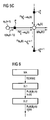
- FIGs. 5A, 5B and 5C show parts of the corresponding factor graph for this simplified algorithm. Particularly, those figures indicate the message propagation on the graph in the sum-product algorithm.
- Fig. 5A shows the part of the factor graph for variable x 1 ( k )
- Fig. 5B shows the part of the graph for variable x 2 ( k )
- Fig. 5C shows in general the part of the graph for variable x n ( k ) .
- solid lines represent messages used within a time step
- dashed lines represent messages passed to the next time step (i.e. the next synchronization cycle).
- E ⁇ R n ( k ) ⁇ is initialized by 1
- P n ( k ) is initialized by N ⁇ ⁇ v n k 2 ⁇ I N in step 0.
- the following part derives the transition from step k -1 to step k .
- Figs. 5A to 5C illustrate the sum-product algorithm. If there is an arrow from node a to node b, then a is a parent of b and b is a child of a. A parent node can pass a "message" to a child node, in the direction indicated by the arrows on the edges. It can be observed in Figs. 5A to 5C that each node has at most one child.
- the messages are real numbers, and namely the values of certain relevant probability density functions. Let m a ⁇ b denote the message from node a to node b .
- the message calculation at each node is carried out according to the sum-product algorithm as follows:
- the only incoming messages at variable node x 2 ( k ) are m f k 2 k ⁇ x 2 k x 2 k and m g k 2 k ⁇ x 2 k x 2 k . .
- the calculation in (49') results in a Gaussian density function.
- x n - 1 k where g
- x n k P n k ⁇ k c n k ⁇ ⁇ ⁇ n k 2 + b n - 1 T k ⁇ ⁇ x n - 1 k ⁇ g k n ⁇ b n - 1 k - 1 ⁇ b n - 1 T k ⁇ ⁇ x n - 1 k ⁇ g k n + ⁇ f k n ⁇ x i k - 1 ⁇ ⁇ f k n ⁇ x i k
- the advantage of the above described sum-product algorithm in comparison to the Kalman filter lies in the fact that no fusion center is needed for estimating the hidden state variables.
- the estimated variable x n ( k ), i.e. its mean x n ( k ) and its covariance matrix P n ( k ) in a slave node n only depends on variables calculated or measured in the previous slave node n-1, i.e. on the previously estimated hidden state variable x n -1 ( k ) and on the bridge delay b n -1 ( k ) of the slave node n-1.
- the estimated hidden state variable only depends on the measured variable TS ( M ( k )) .
- the synchronization messages can pass the relevant variables for calculating the hidden state variables from one node to another.
- Fig. 6 the relevant information carried from a master node MA to the slave node SL1, from the slave node SL1 to the slave node SL2 and from the slave node SL2 to the next slave node are indicated next to corresponding arrows illustrating the transmission of synchronization messages between the nodes.
- each node can calculate the hidden state variable by its own and the variables need not be transmitted to a fusion center in which the calculation is done after collecting known variables from all nodes.
- the estimation of the hidden state variable can be performed in less time, thus resulting in a faster synchronization of the clocks.
Landscapes
- Engineering & Computer Science (AREA)
- Computer Networks & Wireless Communication (AREA)
- Signal Processing (AREA)
- Synchronisation In Digital Transmission Systems (AREA)
Claims (18)
- Verfahren zur Taktsynchronisierung in einem Kommunikationsnetzwerk, das eine Vielzahl von Knoten (MA, SL1, SL2) umfasst, wobei die Knoten (MA, SL1, SL2) einen Master-Knoten (MA) und Slave-Knoten (SL1, SL2) umfassen, wobei der Master-Knoten (MA) einen Master-Taktgeber aufweist, der Master-Zählerwerte auf der Basis eines Master-Zählers mit einer Master-Frequenz erzeugt, und wobei jeder Slave-Knoten (SL1, SL2) einen Slave-Taktgeber aufweist, der Slave-Zählerwerte auf der Basis eines Slave-Zählers mit einer entsprechenden Slave-Frequenz erzeugt, wobei die Taktsynchronisierung in aufeinanderfolgenden Synchronisierungszyklen durchgeführt wird, wobei in einem Synchronisierungszyklus:- Synchronisierungsnachrichten (SY(k)) in einer Folge von Synchronisierungsnachrichten (SY(k)) von dem Master-Knoten (MA) zu einem Slave-Knoten (SL1) und von einem Slave-Knoten (SL1) zu einem anderen Slave-Knoten (SL2) übertragen werden, wobei eine Synchronisierungsnachricht (SY(k)), die von einem Knoten (MA, SL1, SL2) zu einem anderen Knoten (MA, SL1, SL2) gesendet wird, Informationen enthält, die auf einem oder mehreren gemessenen Zählerwerten (TS(M(k)), TS(S1 in(k)), TS(S1 out(k))) des die Synchronisierungsnachricht (SY(k)) sendenden Knotens (MA, SL1, SL2) basieren;- für jeden Slave-Knoten (SL1, SL2) der Master-Zählerwert (x1 in(k), x2 in(k)) für einen gemessenen Slave-Zählerwert (TS(S1 in(k)), TS(S2 in(k))) unter Verwendung eines Schätzverfahrens geschätzt wird, das auf ein stochastisches Modell für Zustandsvariable der Knoten (MA, SL1, SL2) angewendet wird, wobei jeder Slave-Takt auf der Basis des geschätzten Master-Zählerwertes (x1 in(k), x2 in(k)) synchronisiert wird, wobei das stochastische Modell enthält- ein Zustandsübergangsmodell, das die Abhängigkeit von Zustandsvariablen (x1 in(k), x2 in(k), R1(k), R2(k)) von Slave-Knoten (SL1, SL2) in einem Synchronisierungszyklus von Zustandsvariablen von Slave-Knoten (SL1, SL2) im vorhergehenden Synchronisierungszyklus beschreibt;- ein Beobachtungsmodell, das die Abhängigkeit bekannter Variabler (TS(M(k)), bn(k), cn(k)) von Master- und Slave-Knoten (MA, SL1, SL2) von Zustandsvariablen (x1 in(k), x2 in(k) R1(k), R2(k)) von Slave-Knoten (SL1, SL2) beschreibt;und wobei die Zustandsvariablen (x1 in(k), x2 in(k), R1(k), R2(k)) der Slave-Knoten (SL1, SL2) durch das Schätzverfahren geschätzt werden,
dadurch gekennzeichnet, dass das Schätzverfahren auf dem Summen-Produkt-Algorithmus basiert, der auf einen Faktorgraphen angewendet wird, welcher die Beziehungen zwischen bekannten Variablen (TS(M(k)), bn(k), cn(k)) und Zustandsvariablen (x1 in(k), x2 in(k), R1(k), R2(k)) auf der Basis von Nachrichtenflüssen beschreibt. - Verfahren nach Anspruch 1, wobei eine Synchronisierungsnachricht (SY(k)), die von dem Master-Knoten (MA) gesendet wird, den gemessenen Master-Zählerwert (TS(M(k)), wenn die Synchronisierungsnachricht (SY(k)) von dem Master-Knoten (MA) gesendet wird, enthält.
- Verfahren nach Anspruch 1 oder 2, wobei eine Synchronisierungsnachricht (SY(k)), die von einem Slave-Knoten (SL1, SL2) gesendet wird, einen näherungsweisen Master-Zählerwert, wenn die Synchronisierungsnachricht (SY(k)) von dem Slave-Knoten (SL1, SL2) gesendet wird, enthält, wobei der besagte näherungsweise Master-Zählerwert von gemessenen Slave-Zählerwerten (TS(S1 in(k), TS(S1 out(k))) des Slave-Knotens (SL1, SL2) und von Informationen, die in Synchronisierungsnachrichten empfangen wurden, abgeleitet wird.
- Verfahren nach einem der vorhergehenden Ansprüche, wobei eine Synchronisierungsnachricht (SY(k)), die von einem Slave-Knoten (SL1, SL2) gesendet wird, eine gemessene Brückenverzögerung (Bridge Delay) (b1(k), b2(k)) zwischen dem Empfangen der vorhergehenden Synchronisierungsnachricht und dem Senden der Synchronisierungsnachricht (SY(k)) sowie den geschätzten Master-Zählerwert (x1 in(k), x2 in(k)) für den Slave-Knoten (SL1, SL2) enthält.
- Verfahren nach einem der vorhergehenden Ansprüche, wobei das stochastische Modell Messfehler in Bezug auf gemessene Zählerwerte (TS(M(k), TS(S1 in(k), TS(S1 out(k)) sowie Schwankungen des Frequenzverhältnisses ((R1(k), R2(k)) zwischen dem Master-Takt und jedem Slave-Takt beinhaltet.
- Verfahren nach einem der vorhergehenden Ansprüche, wobei die Zustandsvariablen (x1 in(k), x2 in(k), R1(k), R2(k)) den Master-Zählerwert (x1 in(k), x2 in(k)) und das Frequenzverhältnis (R1(k), R2(k)) zwischen der Master-Frequenz und einer Slave-Frequenz, wenn die Synchronisierungsnachricht (SY(k)) in einem Slave-Knoten empfangen wird, umfassen.
- Verfahren nach Anspruch 6, wobei das Zustandsübergangsmodell wie folgt definiert ist:


wobei n auf den n-ten Slave-Knoten (SL1, SL2) verweist, der eine Synchronisierungsnachricht (SY(k)) in der Folge von Synchronisierungsnachrichten (SY(k)) empfängt;
wobei k auf den k-ten Synchronisierungszyklus verweist;
wobei
wobei Rn (k) das Frequenzverhältnis zwischen der Master-Frequenz und der Slave-Frequenz des n-ten Slave-Knotens (SL1, SL2) im k-ten Synchronisierungszyklus ist;
wobei ω n (k) eine Zufallsvariable bezeichnet, welche Frequenzschwankungen modelliert;
wobei α n (k) das in Slave-Zählerwerten gemessene Zeitintervall zwischen dem Empfangen der Synchronisierungsnachricht (SY(k)) im n-ten Slave-Knoten (SL1, SL2) im k-ten Synchronisierungszyklus und dem Empfangen der entsprechenden Synchronisierungsnachricht (SY(k-1)) im n-ten Slave-Knoten (SL1, SL2) im (k-1)-ten Synchronisierungszyklus bezeichnet. - Verfahren nach Anspruch 7, wobei die Zufallsvariable ωn(k) als eine Normalverteilung modelliert ist.
- Verfahren nach einem der vorhergehenden Ansprüche, wobei die bekannten Variablen (TS(M(k)), bn(k), cn(k)) eine separat geschätzte Leitungsverzögerung (cn(k)) in Slave-Zählerwerten zwischen dem Empfangen aufeinanderfolgender Synchronisierungsnachrichten (SY(k)) in einem Slave-Knoten (SL1, SL2), eine gemessene Brückenverzögerung (bn(k)) in Slave-Zählerwerten zwischen dem Empfangen einer Synchronisierungsnachricht (SY(k)) und dem Senden der nächsten Synchronisierungsnachricht in einem Slave-Knoten (SL1, SL2) und den gemessenen Master-Zählerwert (TS(M(k))), wenn der Master-Knoten (MA) eine Synchronisierungsnachricht (SY(k)) sendet, umfassen.
- Verfahren nach Anspruch 9, wobei das Beobachtungsmodell wie folgt definiert ist:


wobei n auf den n-ten Slave-Knoten (SL1, SL2) verweist, der eine Synchronisierungsnachricht (SY(k)) in der Folge von Synchronisierungsnachrichten (SY(k)) empfängt;
wobei k auf den k-ten Synchronisierungszyklus verweist;
wobei TS(M(k)) den gemessenen Master-Zählerwert, wenn der Master-Knoten (MA) die Synchronisierungsnachricht (SY(k)) im k-ten Synchronisierungszyklus sendet, bezeichnet;
wobei
wobei Rn (k) das Frequenzverhältnis zwischen der Master-Frequenz und der Slave-Frequenz des n-ten Slave-Knotens (SL1, SL2) im k-ten Synchronisierungszyklus ist;
wobei cn (k) die separat geschätzte Leitungsverzögerung in Slave-Zählerwerten zwischen dem Empfangen aufeinanderfolgender Synchronisierungsnachrichten (SY(k)) im n-ten Slave-Knoten im k-ten Synchronisierungszyklus bezeichnet;
wobei bn (k) die gemessene Brückenverzögerung in Slave-Zählerwerten zwischen dem Empfangen der Synchronisierungsnachricht (SY(k)) und dem Senden der nächsten Synchronisierungsnachricht (SY(k)) im n-ten Slave-Knoten im k-ten Synchronisierungszyklus bezeichnet;
wobei vn(k) eine Zufallsvariable bezeichnet, welche Messfehler im n-ten Slave-Knoten modelliert. - Verfahren nach Anspruch 10, wobei die Zufallsvariable vn(k) durch eine Normalverteilung modelliert wird, wobei die besagte Normalverteilung vorzugsweise aus Testmusterdaten erzeugt wird.
- Verfahren nach einem der vorhergehenden Ansprüche, wenn abhängig von Anspruch 6, wobei die Zustandsvariablen (x1 in(k), X2 in(k) R1(k), R2(k)) eines Slave-Knotens (SL1, SL2) in dem Slave-Knoten (SL1, SL2) geschätzt werden.
- Verfahren nach einem der vorhergehenden Ansprüche, wobei der Faktorgraph Nebenbedingungen in Bezug auf die Nachrichtenflüsse aufweist, derart, dass Nachrichten nicht von einem Knoten (MA, SL1, SL2), der eine Synchronisierungsnachricht (SY(k)) empfängt, zu einem Knoten, von welchem die Synchronisierungsnachricht (SY(k)) empfangen wird, weitergeleitet werden, und derart, dass Nachrichten nicht zurück in die Vergangenheit übertragen werden.
- Verfahren nach einem der vorhergehenden Ansprüche, wobei die Taktsynchronisierung auf dem Standard IEEE 1588 basiert.
- Verfahren nach einem der vorhergehenden Ansprüche, wobei die Knoten (MA, SL1, SL2) auf der Basis des PROFINET-Standards miteinander kommunizieren.
- Verfahren nach einem der vorhergehenden Ansprüche, wobei das Verfahren in einem industriellen Automatisierungssystem angewendet wird.
- Kommunikationsnetzwerk, das eine Vielzahl von Knoten (MA, SL1, SL2) umfasst, wobei die Knoten (MA, SL1, SL2) einen Master-Knoten (MA) und Slave-Knoten (SL1, SL2) umfassen, wobei der Master-Knoten (MA) einen Master-Taktgeber aufweist, der Master-Zählerwerte auf der Basis eines Master-Zählers mit einer Master-Frequenz erzeugt, und wobei jeder Slave-Knoten (SL1, SL2) einen Slave-Taktgeber aufweist, der Slave-Zählerwerte auf der Basis eines Slave-Zählers mit einer entsprechenden Slave-Frequenz erzeugt, wobei die Knoten in dem Kommunikationsnetzwerk dazu eingerichtet sind, eine Taktsynchronisierung in aufeinanderfolgenden Synchronisierungszyklen durchzuführen, derart, dass in einem Synchronisierungszyklus:- Synchronisierungsnachrichten (SY(k)) in einer Folge von Synchronisierungsnachrichten (SY(k)) von dem Master-Knoten (MA) zu einem Slave-Knoten (SL1) und von einem Slave-Knoten (SL1) zu einem anderen Slave-Knoten (SL2) übertragen werden, wobei eine Synchronisierungsnachricht (SY(k)), die von einem Knoten (MA, SL1, SL2) zu einem anderen Knoten (MA, SL1, SL2) gesendet wird, Informationen enthält, die auf einem oder mehreren gemessenen Zählerwerten (TS(M(k)), TS(S1 in(k)), TS(S1 out(k))) des die Synchronisierungsnachricht (SY(k)) sendenden Knotens (MA, SL1, SL2) basieren;- für jeden Slave-Knoten (SL1, SL2) der Master-Zählerwert (x1 in(k), x2 in(k)) für einen gemessenen Slave-Zählerwert (TS(S1 in(k)), TS(S2 in(k))) unter Verwendung eines Zustandsschätzverfahrens geschätzt wird, das auf ein stochastisches Modell für Zustandsvariable der Knoten (MA, SL1, SL2) angewendet wird, wobei jeder Slave-Takt auf der Basis des geschätzten Master-Zählerwertes (x1 in(k), x2 in(k)) synchronisiert wird, wobei das stochastische Modell enthält- ein Zustandsübergangsmodell, das die Abhängigkeit von Zustandsvariablen (x1 in(k), x2 in(k), R1(k), R2(k)) von Slave-Knoten (SL1, SL2) in einem Synchronisierungszyklus von Zustandsvariablen von Slave-Knoten (SL1, SL2) im vorhergehenden Synchronisierungszyklus beschreibt;- ein Beobachtungsmodell, das die Abhängigkeit bekannter Variabler (TS(M(k)), bn(k), cn(k)) von Master- und Slave-Knoten (MA, SL1, SL2) von Zustandsvariablen (x1 in(k), x2 in(k), R1(k), R2(k)) von Slave-Knoten (SL1, SL2) beschreibt;und wobei die Zustandsvariablen (x1 in(k), x2 in(k), R1(k), R2(k)) der Slave-Knoten (SL1, SL2) durch das Schätzverfahren geschätzt werden,
dadurch gekennzeichnet, dass das Schätzverfahren auf dem Summen-Produkt-Algorithmus basiert, der auf einen Faktorgraphen angewendet wird, welcher die Beziehungen zwischen bekannten Variablen (TS(M(k)), bn(k), cn(k)) und Zustandsvariablen (x1 in(k), x2 in(k), R1(k), R2(k)) auf der Basis von Nachrichtenflüssen beschreibt. - Kommunikationsnetzwerk nach Anspruch 17, welches dazu eingerichtet ist, ein Verfahren nach einem der Ansprüche 2 bis 16 auszuführen.
Applications Claiming Priority (1)
| Application Number | Priority Date | Filing Date | Title |
|---|---|---|---|
| EP09012028A EP2299613B1 (de) | 2009-09-22 | 2009-09-22 | Verfahren zur Taktsynchronisierung in einem Kommunikationsnetzwerk |
Related Parent Applications (1)
| Application Number | Title | Priority Date | Filing Date |
|---|---|---|---|
| EP09012028.8 Division | 2009-09-22 |
Publications (2)
| Publication Number | Publication Date |
|---|---|
| EP2385641A1 EP2385641A1 (de) | 2011-11-09 |
| EP2385641B1 true EP2385641B1 (de) | 2013-04-03 |
Family
ID=41480330
Family Applications (2)
| Application Number | Title | Priority Date | Filing Date |
|---|---|---|---|
| EP09012028A Not-in-force EP2299613B1 (de) | 2009-09-22 | 2009-09-22 | Verfahren zur Taktsynchronisierung in einem Kommunikationsnetzwerk |
| EP11006429A Not-in-force EP2385641B1 (de) | 2009-09-22 | 2009-09-22 | Verfahren zur Taktsynchronisierung in einem Kommunikationsnetzwerk |
Family Applications Before (1)
| Application Number | Title | Priority Date | Filing Date |
|---|---|---|---|
| EP09012028A Not-in-force EP2299613B1 (de) | 2009-09-22 | 2009-09-22 | Verfahren zur Taktsynchronisierung in einem Kommunikationsnetzwerk |
Country Status (2)
| Country | Link |
|---|---|
| EP (2) | EP2299613B1 (de) |
| AT (1) | ATE533240T1 (de) |
Families Citing this family (7)
| Publication number | Priority date | Publication date | Assignee | Title |
|---|---|---|---|---|
| DE102010022525A1 (de) | 2010-02-11 | 2012-05-10 | Siemens Aktiengesellschaft | Verfahren zur Zeitsynchronisation in einem Kommunikationsnetz |
| EP2434674B1 (de) | 2010-09-24 | 2013-10-30 | Siemens Aktiengesellschaft | Verfahren zur Zeitsynchronisation in einem Kommunikationsnetz |
| CN104660361A (zh) * | 2015-02-11 | 2015-05-27 | 杨德朝 | 分布式网络授时的滤波方法 |
| CN105553598B (zh) * | 2016-01-10 | 2017-09-29 | 北京航空航天大学 | 一种基于m估计稳健回归的时间触发以太网时钟补偿方法 |
| CN112929121B (zh) * | 2021-04-21 | 2022-04-19 | 中国科学技术大学 | 时钟同步网络、时钟触发网络及实时触发处理方法 |
| CN114189306B (zh) * | 2021-12-03 | 2024-03-12 | 中国国家铁路集团有限公司 | 数据同步系统、方法和装置 |
| CN118945796B (zh) * | 2024-07-03 | 2025-11-18 | 北京自动化控制设备研究所 | 一种基于双向无线通信的运动节点速度和钟漂估计方法 |
Family Cites Families (1)
| Publication number | Priority date | Publication date | Assignee | Title |
|---|---|---|---|---|
| US7103124B1 (en) * | 1999-12-30 | 2006-09-05 | Telefonaktiebolaget Lm Ericsson (Publ) | Synchronization of nodes |
-
2009
- 2009-09-22 EP EP09012028A patent/EP2299613B1/de not_active Not-in-force
- 2009-09-22 AT AT09012028T patent/ATE533240T1/de active
- 2009-09-22 EP EP11006429A patent/EP2385641B1/de not_active Not-in-force
Also Published As
| Publication number | Publication date |
|---|---|
| EP2299613B1 (de) | 2011-11-09 |
| ATE533240T1 (de) | 2011-11-15 |
| EP2385641A1 (de) | 2011-11-09 |
| EP2299613A1 (de) | 2011-03-23 |
Similar Documents
| Publication | Publication Date | Title |
|---|---|---|
| EP2299613B1 (de) | Verfahren zur Taktsynchronisierung in einem Kommunikationsnetzwerk | |
| US8959381B2 (en) | Method and system for clock offset and skew estimation | |
| CN103141039B (zh) | 用于在通讯网络中的时间同步的方法 | |
| US10404393B2 (en) | Clock synchronization method and apparatus | |
| JP5161363B2 (ja) | 非同期分散システムにおけるクロックの同期 | |
| EP3289706B1 (de) | Verfahren, system und vorrichtung zur taktsynchronisierung über zeitvariable und verlustbehaftete netzwerke | |
| US20200162181A1 (en) | Network apparatus and clock synchronization method | |
| US10608764B2 (en) | Methods and systems for synchronization using delay asymmetry | |
| EP2893656B1 (de) | Verfahren und vorrichtung zur schätzung von uhrdifferenz und gangunterschied | |
| US20120320902A1 (en) | Method for Time Synchronization in a Communication Network | |
| Badie-Modiri et al. | Efficient limited-time reachability estimation in temporal networks | |
| CN105594146A (zh) | 用于补偿路径不对称的方法和设备 | |
| Ha et al. | Clock offset estimation for systems with asymmetric packet delays | |
| CN113572560A (zh) | 用于确定时钟同步精度的方法、电子设备和存储介质 | |
| Avraham et al. | A novel clock skew estimator and its performance for the IEEE 1588v2 (PTP) case in fractional Gaussian noise/generalized fractional Gaussian noise environment | |
| Jabbarifar | On line trace synchronization for large scale distributed systems | |
| EP3545633B1 (de) | Verfahren und systeme zur synchronisierung mit verzögerungsasymmetrie | |
| EP3469747B1 (de) | Verfahren und systeme zur schräglagenschätzung | |
| Caballero-Aguila et al. | A new estimation algorithm from measurements with multiple‐step random delays and packet dropouts | |
| Guarro et al. | A Hybrid Observer for Linear Systems under Delayed Sporadic Measurements | |
| EP3545634B1 (de) | Verfahren und systeme zum bestimmen optimaler nachrichten | |
| Na et al. | A Kalman filter approach to clock synchronization of cascaded network elements | |
| Alhashmi | Accurate Network Synchronization via Machine-Learning Based Path Asymmetry Estimation | |
| CN105071890A (zh) | 一种具有高度鲁棒性的自适应时钟同步方法 | |
| Yang et al. | Accurate and Lightweight IEEE 802.1 as Synchronization Algorithm for Airborne Time Sensitive Networks |
Legal Events
| Date | Code | Title | Description |
|---|---|---|---|
| AC | Divisional application: reference to earlier application |
Ref document number: 2299613 Country of ref document: EP Kind code of ref document: P |
|
| AK | Designated contracting states |
Kind code of ref document: A1 Designated state(s): AT BE BG CH CY CZ DE DK EE ES FI FR GB GR HR HU IE IS IT LI LT LU LV MC MK MT NL NO PL PT RO SE SI SK SM TR |
|
| AX | Request for extension of the european patent |
Extension state: AL BA RS |
|
| PUAI | Public reference made under article 153(3) epc to a published international application that has entered the european phase |
Free format text: ORIGINAL CODE: 0009012 |
|
| 17P | Request for examination filed |
Effective date: 20111021 |
|
| RIC1 | Information provided on ipc code assigned before grant |
Ipc: H04J 3/06 20060101AFI20120822BHEP |
|
| GRAP | Despatch of communication of intention to grant a patent |
Free format text: ORIGINAL CODE: EPIDOSNIGR1 |
|
| RIN1 | Information on inventor provided before grant (corrected) |
Inventor name: NA, CHONGNING Inventor name: SCHEITERER, RUXANDRA Inventor name: OBRADOVIC, DRAGAN |
|
| GRAS | Grant fee paid |
Free format text: ORIGINAL CODE: EPIDOSNIGR3 |
|
| GRAA | (expected) grant |
Free format text: ORIGINAL CODE: 0009210 |
|
| RAP1 | Party data changed (applicant data changed or rights of an application transferred) |
Owner name: SIEMENS AKTIENGESELLSCHAFT |
|
| AC | Divisional application: reference to earlier application |
Ref document number: 2299613 Country of ref document: EP Kind code of ref document: P |
|
| AK | Designated contracting states |
Kind code of ref document: B1 Designated state(s): AT BE BG CH CY CZ DE DK EE ES FI FR GB GR HR HU IE IS IT LI LT LU LV MC MK MT NL NO PL PT RO SE SI SK SM TR |
|
| REG | Reference to a national code |
Ref country code: GB Ref legal event code: FG4D |
|
| REG | Reference to a national code |
Ref country code: AT Ref legal event code: REF Ref document number: 605287 Country of ref document: AT Kind code of ref document: T Effective date: 20130415 Ref country code: CH Ref legal event code: EP |
|
| REG | Reference to a national code |
Ref country code: IE Ref legal event code: FG4D |
|
| REG | Reference to a national code |
Ref country code: DE Ref legal event code: R096 Ref document number: 602009014674 Country of ref document: DE Effective date: 20130529 |
|
| REG | Reference to a national code |
Ref country code: AT Ref legal event code: MK05 Ref document number: 605287 Country of ref document: AT Kind code of ref document: T Effective date: 20130403 |
|
| PG25 | Lapsed in a contracting state [announced via postgrant information from national office to epo] |
Ref country code: SI Free format text: LAPSE BECAUSE OF FAILURE TO SUBMIT A TRANSLATION OF THE DESCRIPTION OR TO PAY THE FEE WITHIN THE PRESCRIBED TIME-LIMIT Effective date: 20130403 |
|
| REG | Reference to a national code |
Ref country code: NL Ref legal event code: VDEP Effective date: 20130403 |
|
| REG | Reference to a national code |
Ref country code: LT Ref legal event code: MG4D |
|
| PG25 | Lapsed in a contracting state [announced via postgrant information from national office to epo] |
Ref country code: SE Free format text: LAPSE BECAUSE OF FAILURE TO SUBMIT A TRANSLATION OF THE DESCRIPTION OR TO PAY THE FEE WITHIN THE PRESCRIBED TIME-LIMIT Effective date: 20130403 Ref country code: FI Free format text: LAPSE BECAUSE OF FAILURE TO SUBMIT A TRANSLATION OF THE DESCRIPTION OR TO PAY THE FEE WITHIN THE PRESCRIBED TIME-LIMIT Effective date: 20130403 Ref country code: AT Free format text: LAPSE BECAUSE OF FAILURE TO SUBMIT A TRANSLATION OF THE DESCRIPTION OR TO PAY THE FEE WITHIN THE PRESCRIBED TIME-LIMIT Effective date: 20130403 Ref country code: NL Free format text: LAPSE BECAUSE OF FAILURE TO SUBMIT A TRANSLATION OF THE DESCRIPTION OR TO PAY THE FEE WITHIN THE PRESCRIBED TIME-LIMIT Effective date: 20130403 Ref country code: NO Free format text: LAPSE BECAUSE OF FAILURE TO SUBMIT A TRANSLATION OF THE DESCRIPTION OR TO PAY THE FEE WITHIN THE PRESCRIBED TIME-LIMIT Effective date: 20130703 Ref country code: GR Free format text: LAPSE BECAUSE OF FAILURE TO SUBMIT A TRANSLATION OF THE DESCRIPTION OR TO PAY THE FEE WITHIN THE PRESCRIBED TIME-LIMIT Effective date: 20130704 Ref country code: IS Free format text: LAPSE BECAUSE OF FAILURE TO SUBMIT A TRANSLATION OF THE DESCRIPTION OR TO PAY THE FEE WITHIN THE PRESCRIBED TIME-LIMIT Effective date: 20130803 Ref country code: PT Free format text: LAPSE BECAUSE OF FAILURE TO SUBMIT A TRANSLATION OF THE DESCRIPTION OR TO PAY THE FEE WITHIN THE PRESCRIBED TIME-LIMIT Effective date: 20130805 Ref country code: LT Free format text: LAPSE BECAUSE OF FAILURE TO SUBMIT A TRANSLATION OF THE DESCRIPTION OR TO PAY THE FEE WITHIN THE PRESCRIBED TIME-LIMIT Effective date: 20130403 Ref country code: ES Free format text: LAPSE BECAUSE OF FAILURE TO SUBMIT A TRANSLATION OF THE DESCRIPTION OR TO PAY THE FEE WITHIN THE PRESCRIBED TIME-LIMIT Effective date: 20130714 Ref country code: BE Free format text: LAPSE BECAUSE OF FAILURE TO SUBMIT A TRANSLATION OF THE DESCRIPTION OR TO PAY THE FEE WITHIN THE PRESCRIBED TIME-LIMIT Effective date: 20130403 |
|
| PG25 | Lapsed in a contracting state [announced via postgrant information from national office to epo] |
Ref country code: LV Free format text: LAPSE BECAUSE OF FAILURE TO SUBMIT A TRANSLATION OF THE DESCRIPTION OR TO PAY THE FEE WITHIN THE PRESCRIBED TIME-LIMIT Effective date: 20130403 Ref country code: HR Free format text: LAPSE BECAUSE OF FAILURE TO SUBMIT A TRANSLATION OF THE DESCRIPTION OR TO PAY THE FEE WITHIN THE PRESCRIBED TIME-LIMIT Effective date: 20130403 Ref country code: BG Free format text: LAPSE BECAUSE OF FAILURE TO SUBMIT A TRANSLATION OF THE DESCRIPTION OR TO PAY THE FEE WITHIN THE PRESCRIBED TIME-LIMIT Effective date: 20130703 Ref country code: CY Free format text: LAPSE BECAUSE OF FAILURE TO SUBMIT A TRANSLATION OF THE DESCRIPTION OR TO PAY THE FEE WITHIN THE PRESCRIBED TIME-LIMIT Effective date: 20130403 Ref country code: PL Free format text: LAPSE BECAUSE OF FAILURE TO SUBMIT A TRANSLATION OF THE DESCRIPTION OR TO PAY THE FEE WITHIN THE PRESCRIBED TIME-LIMIT Effective date: 20130403 |
|
| PG25 | Lapsed in a contracting state [announced via postgrant information from national office to epo] |
Ref country code: SK Free format text: LAPSE BECAUSE OF FAILURE TO SUBMIT A TRANSLATION OF THE DESCRIPTION OR TO PAY THE FEE WITHIN THE PRESCRIBED TIME-LIMIT Effective date: 20130403 Ref country code: DK Free format text: LAPSE BECAUSE OF FAILURE TO SUBMIT A TRANSLATION OF THE DESCRIPTION OR TO PAY THE FEE WITHIN THE PRESCRIBED TIME-LIMIT Effective date: 20130403 Ref country code: EE Free format text: LAPSE BECAUSE OF FAILURE TO SUBMIT A TRANSLATION OF THE DESCRIPTION OR TO PAY THE FEE WITHIN THE PRESCRIBED TIME-LIMIT Effective date: 20130403 Ref country code: CZ Free format text: LAPSE BECAUSE OF FAILURE TO SUBMIT A TRANSLATION OF THE DESCRIPTION OR TO PAY THE FEE WITHIN THE PRESCRIBED TIME-LIMIT Effective date: 20130403 |
|
| PLBE | No opposition filed within time limit |
Free format text: ORIGINAL CODE: 0009261 |
|
| STAA | Information on the status of an ep patent application or granted ep patent |
Free format text: STATUS: NO OPPOSITION FILED WITHIN TIME LIMIT |
|
| PG25 | Lapsed in a contracting state [announced via postgrant information from national office to epo] |
Ref country code: RO Free format text: LAPSE BECAUSE OF FAILURE TO SUBMIT A TRANSLATION OF THE DESCRIPTION OR TO PAY THE FEE WITHIN THE PRESCRIBED TIME-LIMIT Effective date: 20130403 |
|
| 26N | No opposition filed |
Effective date: 20140106 |
|
| REG | Reference to a national code |
Ref country code: DE Ref legal event code: R097 Ref document number: 602009014674 Country of ref document: DE Effective date: 20140106 |
|
| PG25 | Lapsed in a contracting state [announced via postgrant information from national office to epo] |
Ref country code: MC Free format text: LAPSE BECAUSE OF FAILURE TO SUBMIT A TRANSLATION OF THE DESCRIPTION OR TO PAY THE FEE WITHIN THE PRESCRIBED TIME-LIMIT Effective date: 20130403 |
|
| REG | Reference to a national code |
Ref country code: CH Ref legal event code: PL |
|
| REG | Reference to a national code |
Ref country code: IE Ref legal event code: MM4A |
|
| PG25 | Lapsed in a contracting state [announced via postgrant information from national office to epo] |
Ref country code: LI Free format text: LAPSE BECAUSE OF NON-PAYMENT OF DUE FEES Effective date: 20130930 Ref country code: CH Free format text: LAPSE BECAUSE OF NON-PAYMENT OF DUE FEES Effective date: 20130930 Ref country code: IE Free format text: LAPSE BECAUSE OF NON-PAYMENT OF DUE FEES Effective date: 20130922 |
|
| PG25 | Lapsed in a contracting state [announced via postgrant information from national office to epo] |
Ref country code: SM Free format text: LAPSE BECAUSE OF FAILURE TO SUBMIT A TRANSLATION OF THE DESCRIPTION OR TO PAY THE FEE WITHIN THE PRESCRIBED TIME-LIMIT Effective date: 20130403 |
|
| PG25 | Lapsed in a contracting state [announced via postgrant information from national office to epo] |
Ref country code: MT Free format text: LAPSE BECAUSE OF FAILURE TO SUBMIT A TRANSLATION OF THE DESCRIPTION OR TO PAY THE FEE WITHIN THE PRESCRIBED TIME-LIMIT Effective date: 20130403 Ref country code: TR Free format text: LAPSE BECAUSE OF FAILURE TO SUBMIT A TRANSLATION OF THE DESCRIPTION OR TO PAY THE FEE WITHIN THE PRESCRIBED TIME-LIMIT Effective date: 20130403 |
|
| PG25 | Lapsed in a contracting state [announced via postgrant information from national office to epo] |
Ref country code: MK Free format text: LAPSE BECAUSE OF FAILURE TO SUBMIT A TRANSLATION OF THE DESCRIPTION OR TO PAY THE FEE WITHIN THE PRESCRIBED TIME-LIMIT Effective date: 20130403 Ref country code: HU Free format text: LAPSE BECAUSE OF FAILURE TO SUBMIT A TRANSLATION OF THE DESCRIPTION OR TO PAY THE FEE WITHIN THE PRESCRIBED TIME-LIMIT; INVALID AB INITIO Effective date: 20090922 Ref country code: LU Free format text: LAPSE BECAUSE OF NON-PAYMENT OF DUE FEES Effective date: 20130922 |
|
| REG | Reference to a national code |
Ref country code: FR Ref legal event code: PLFP Year of fee payment: 8 |
|
| PGFP | Annual fee paid to national office [announced via postgrant information from national office to epo] |
Ref country code: GB Payment date: 20160914 Year of fee payment: 8 |
|
| REG | Reference to a national code |
Ref country code: FR Ref legal event code: PLFP Year of fee payment: 9 |
|
| GBPC | Gb: european patent ceased through non-payment of renewal fee |
Effective date: 20170922 |
|
| PG25 | Lapsed in a contracting state [announced via postgrant information from national office to epo] |
Ref country code: GB Free format text: LAPSE BECAUSE OF NON-PAYMENT OF DUE FEES Effective date: 20170922 |
|
| REG | Reference to a national code |
Ref country code: FR Ref legal event code: PLFP Year of fee payment: 10 |
|
| PGFP | Annual fee paid to national office [announced via postgrant information from national office to epo] |
Ref country code: FR Payment date: 20190918 Year of fee payment: 11 |
|
| PGFP | Annual fee paid to national office [announced via postgrant information from national office to epo] |
Ref country code: DE Payment date: 20191119 Year of fee payment: 11 |
|
| PGFP | Annual fee paid to national office [announced via postgrant information from national office to epo] |
Ref country code: IT Payment date: 20190926 Year of fee payment: 11 |
|
| REG | Reference to a national code |
Ref country code: DE Ref legal event code: R119 Ref document number: 602009014674 Country of ref document: DE |
|
| PG25 | Lapsed in a contracting state [announced via postgrant information from national office to epo] |
Ref country code: DE Free format text: LAPSE BECAUSE OF NON-PAYMENT OF DUE FEES Effective date: 20210401 Ref country code: FR Free format text: LAPSE BECAUSE OF NON-PAYMENT OF DUE FEES Effective date: 20200930 |
|
| PG25 | Lapsed in a contracting state [announced via postgrant information from national office to epo] |
Ref country code: IT Free format text: LAPSE BECAUSE OF NON-PAYMENT OF DUE FEES Effective date: 20200922 |