EP3545633B1 - Verfahren und systeme zur synchronisierung mit verzögerungsasymmetrie - Google Patents
Verfahren und systeme zur synchronisierung mit verzögerungsasymmetrie Download PDFInfo
- Publication number
- EP3545633B1 EP3545633B1 EP16805886.5A EP16805886A EP3545633B1 EP 3545633 B1 EP3545633 B1 EP 3545633B1 EP 16805886 A EP16805886 A EP 16805886A EP 3545633 B1 EP3545633 B1 EP 3545633B1
- Authority
- EP
- European Patent Office
- Prior art keywords
- time
- client
- message
- timing
- server
- Prior art date
- Legal status (The legal status is an assumption and is not a legal conclusion. Google has not performed a legal analysis and makes no representation as to the accuracy of the status listed.)
- Active
Links
Images

Classifications
-
- H—ELECTRICITY
- H04—ELECTRIC COMMUNICATION TECHNIQUE
- H04J—MULTIPLEX COMMUNICATION
- H04J3/00—Time-division multiplex systems
- H04J3/02—Details
- H04J3/06—Synchronising arrangements
- H04J3/0635—Clock or time synchronisation in a network
- H04J3/0638—Clock or time synchronisation among nodes; Internode synchronisation
- H04J3/0658—Clock or time synchronisation among packet nodes
- H04J3/0661—Clock or time synchronisation among packet nodes using timestamps
- H04J3/0667—Bidirectional timestamps, e.g. NTP or PTP for compensation of clock drift and for compensation of propagation delays
Definitions
- the present invention relates to methods and systems for synchronization taking into account delay asymmetry. It is particularly, but not exclusively, related to methods and systems which make use of the delay asymmetry to improve the accuracy of the estimation algorithm used to estimate the phase offset in a synchronization algorithm (for example under IEEE 1588 PTP).
- Timing synchronization using a protocol such as IEEE 1588 PTP and a well-designed slave clock recovery mechanism can provide time synchronization in the sub-microsecond level and lower. Time synchronization requires an accurate measurement of the communication path delay between the time server (master) and the client (slave) in order to compute the time offset between them.
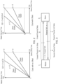
- the PTP message exchange process (i.e., the PTP Delay Request/Delay Response flow) between a master and a slave is illustrated in Figure 1 and described below.
- IEEE 1588 PTP allows for two different types of timestamping methods, either one-step or two-step.
- One-step clocks update time information within event messages (Sync and Delay_Req) on-the-fly, while two-step clocks convey the precise timestamps of packets in general messages (Follow_Up and Delay_Resp).
- a Sync message is transmitted by a master 1 to its slaves 3 and either contains the exact time of its transmission or is followed by a Follow_Up message containing this time.
- the Follow_Up message communicates the value of the departure timestamp for a particular Sync message.
- Figure 1 illustrates the basic pattern of synchronization message exchanges for the two-step clocks.
- the master 1 sends a Sync message to the slave 3 over the packet network 2 and notes the time T 1 at which it was sent.
- the slave receives the Sync message and notes the time of reception T 2 .
- the master 1 conveys to the slave 3 the timestamp T 1 by one of two ways: 1) Embedding the timestamp T 1 in the Sync message. This requires some sort of hardware processing (i.e., hardware timestamping) for highest accuracy and precision. 2) Embedding the timestamp T 1 a Follow_Up message which is the sent to the slave (as shown in Figure 1 ).
- the slave 3 sends a Delay_Req message to the master 1 and notes the time T 3 at which it was sent.
- the master receives the Delay_Req message and notes the time of reception T 4 .
- the master 1 conveys to the slave 3 the timestamp T 4 by embedding it in a Delay_Resp message.
- the slave 3 At the end of this PTP message exchange, the slave 3 possesses all four timestamps ⁇ T 1 , T 2 , T 3 , T 4 ⁇ . These timestamps may be used to compute the offset of the slave's clock 5 with respect to the master clock 4 and the mean propagation time of messages between the two clocks.
- the computation of offset and propagation time assumes that the master-to-slave and slave-to-master propagation times are equal, i.e. that there is a symmetrical communication path. Clock frequencies change over time, so periodic message exchanges are required. Because these clock variations change slowly, the period between message exchanges is typically on the order of milliseconds to seconds.
- the path delay estimation is based on the important assumption that the time delay from master to slave is equal to that from slave to master.
- the communication paths are not perfectly symmetric, mainly due to dissimilar forward and reverse physical link delays and queuing delays.
- queuing delays which are variable, can still exist when timing messages go through the packet network and are queued for forwarding.
- the processing and buffering of packets in network devices introduce variations in the time latency of packets traversing the packet network. This mainly happens when timing transfer is done in an end-to-end manner without any form of timing assistance from the network to help mitigate the effects of the variable queuing delays.
- US 9,184,861B uses the variance of the difference between the forward and reverse message packet delay variations (“PDVs”) as the measurement noise term for the Kalman filter realisation. This measurement noise term is used directly by the Kalman filter estimation algorithm.
- the approach in US 9,184,861 B2 is to accept that there is noise introduced by the queueing delays and then try to represent this noise faithfully.
- US 2015/092794A discloses methods and devices for compensating for path asymmetry, particularly with reference to time and frequency synchronization.
- the methods have particular application where time and frequency synchronization over packet networks using, for example, the IEEE 1588 Precision Time Protocol (PTP) is being carried out.
- PTP Precision Time Protocol
- communication path delays between a time server (master) and a client (slave) are estimated using the assumption that the forward delay on the path is the same as the reverse delay.
- differences between these delays can cause errors in the estimation of the offset of the slave clock from that of the master.
- An object of the present invention is to provide an improved way of accounting for the delay asymmetry when estimating the phase offset of a slave clock.
- a further object of the present invention is to provide a way of maintaining the accuracy of estimations during periods of high load on one of the forward and reverse channels in a timing network.
- aspects of the present invention provide for methods and systems which estimate the phase offset of a slave clock by taking into account an estimated measure of the asymmetry in the transmission paths between the time server and the time client.
- a first aspect of the present invention provides a method of estimating a phase offset of a local clock in a time client compared with a master clock in a time server, connected to the time client over a network, the method including the steps of: sending first timing messages in a forward direction from the time server to the time client and second timing messages in a reverse direction from the time client to the time server, and recording timestamps which are the times of sending and times of receipt of the timing messages; estimating, for each message in a window of predetermined length, the transmission delay experienced by the message; determining, from said estimates, a minimum estimated delay experienced by timing messages in the forward direction in that window, and a minimum estimated delay experienced by timing messages in the reverse direction in that window; determining, for each message in that window, the difference between the estimated transmission delay for that message and the minimum estimated delay for messages travelling in the same direction as that message; determining, from said differences, a queuing asymmetry measure for each exchange of first and second timing messages in that window; estimating the phase offset of the local clock at
- the network may be a packet network (using technologies such Ethernet, IP, MPLS, etc.).
- the timing messages are preferably timing messages under the IEEE 1588 Precision Time Protocol (PTP).
- PTP Precision Time Protocol
- the noise introduced by the queueing delays can be reduced by using the estimations of the queueing delays.
- the method according to this aspect may significantly reduce the errors in phase offset estimation which result from variable and asymmetrical queueing delays.
- the method of the present aspect preferably uses a queuing asymmetry measure (preferably based on good estimations of the difference in the forward and reverse delays) directly in an estimation algorithm (such as a Kalman filter algorithm) as an integral part of the estimation process, rather than as a modifier to be applied after the operation of the estimation algorithm.
- an estimation algorithm such as a Kalman filter algorithm
- This particular queuing asymmetry measure has been found to be particularly close to the true queuing asymmetry in the delay for a particular pair of timing messages, whilst being calculated from values which are readily determined from the message exchange and estimations obtained in the method of the present aspect.
- the step of determining the queuing asymmetry measure includes: determining, from said timestamps, a forward displacement factor which is the difference between the interval between the times of receipt of successive first timing messages by the client and the interval between the times of sending of said successive first messages by the server; determining, from said timestamps, a reverse displacement factor which is the difference between the interval between the times of receipt of successive second timing messages by the server and the interval between the times of sending of said successive second timing messages by the client; maintaining a running sum of said forward displacement factors over a predetermined time period; maintaining a running sum of reverse displacement factors over a predetermined time period; and calculating the queuing asymmetry measure from said sums.
- the Kalman filter may converge much more rapidly on its solution.
- the method may further include determining the load conditions on the forward and reverse transmission paths. This may be of particular benefit in allowing stored values for minimum delays or minimum displacements from times when the load conditions are determined to be low to generate better estimates of minimum delays or minimum displacements when one of the transmission paths has high load conditions.
- the load conditions on a particular path can cause significant bias and/or error in estimating minimum values and this can lead to errors or inefficiency in estimating phase offset.
- minima By storing minima during periods of low load conditions, these minima can be used later to estimate the "true" minima when a path is under high load and may be more accurate than the minimum determined from the timing messages sent under those conditions.
- the method may further include the steps of: determining, from said timestamps, a forward displacement factor which is the difference between the interval between the times of receipt of successive first timing messages by the client and the interval between the times of sending of said successive first messages by the server; determining, from said timestamps, a reverse displacement factor which is the difference between the interval between the times of receipt of successive second timing messages by the server and the interval between the times of sending of said successive second timing messages by the client; maintaining a running sum of said forward displacement factors over a predetermined time period; maintaining a running sum of reverse displacement factors over a predetermined time period; determining a noise condition of the forward transmission path and a noise condition of the reverse transmission path over said predetermined time period; if it is determined that both the forward and reverse transmission paths have a low noise condition during said predetermined time period, determining a minimum of the sum of forward displacement factors and a minimum of the sum of reverse displacement factors over that period of time and storing the determined minima as reference minimum values; and if it is determined during
- the step of determining a noise condition on a transmission path may involve: calculating, based on the timestamps, a variance of a queuing delay on that path; applying a first moving average having a first time constant to the variance; applying a second moving average having a second time constant greater than the first time constant to the variance; calculating a difference between the first and second moving averages; and comparing the calculated difference to a threshold to determine a noise condition on the path.
- the moving averages may be exponentially-weighted moving averages (EWMAs).
- EWMAs exponentially-weighted moving averages
- Using a pair of moving averages allows determination of whether the current noise conditions (as represented by the moving average with the shorter time constant) have changed from an earlier steady-state period (as represented by the moving average with the longer time constant).
- the threshold can be set a-priori if the conditions of the detection environment are known in advance or the threshold can be determined experimentally during operation (or a combination of both may be employed).
- P P 11 P 12 P 21 P 22
- P 11 the error variance of the phase offset
- P 22 the error variance of the skew (fractional frequency offset)
- P 12 and P 21 represent the error covariance between the phase offset and the skew.
- P 22 depends on the oscillator's stability, its variance, i.e., the variance of the P 22 term itself, is extremely low (almost non-existent). P 22 changes significantly only due to the external noise (and the primary external noise input is typically caused by forward and/or backward traffic load changes).
- P 22 When external noise changes occur (e.g. the traffic load changes), P 22 reflects this by converging to a new stable level of error variance. Due to the filtering properties of the Kalman filter, this new level is, again, very stable (i.e., there is almost no variance). However, the magnitude of the new level will be very distinct from the previous state, provided there was a significant enough change in the noise conditions. Therefore, P 22 can be employed as input provide reliable indications of changing load conditions.
- the method of the present aspect may include any combination of some, all or none of the above described preferred and optional features.
- the method of the above aspect is preferably implemented by a time client according to the second aspect of this invention or a networked time system according to the third aspect of this invention, as described below, but need not be.
- a second aspect of the present invention provides a time client having a local clock and a processor, and connected over a network to a time server having a master clock, wherein the time client is arranged to: receive first timing messages sent in a forward direction from the time server to the time client; and send second timing messages in a reverse direction from the time client to the time server, record timestamps which are the times of sending and times of receipt of the timing messages by the time client; and receive timestamps which are the times of sending and the times of receipt of the timing messages by the time server, wherein the processor is arranged to: estimate, for each message in a window of predetermined length, the transmission delay experienced by the message; determine, from said estimates, a minimum estimated delay experienced by timing messages in the forward direction in that window, and a minimum estimated delay experienced by timing messages in the reverse direction in that window; determine, for each message in that window, the difference between the estimated transmission delay for that message and the minimum estimated delay for messages travelling in the same direction as that message; determine, from said differences, a queu
- the network may be a packet network (using technologies such Ethernet, IP, MPLS, etc.).
- the timing messages are preferably timing messages under the IEEE 1588 Precision Time Protocol (PTP).
- PTP Precision Time Protocol
- the noise introduced by the queueing delays and the corresponding effects on offset estimation can be reduced by using the estimations of the queueing delays.
- time client of the present aspect may significantly reduce the errors in phase offset estimation which result from variable and asymmetrical queueing delays.
- the processor of the time client of the present aspect preferably uses a queuing asymmetry measure (preferably based on good estimations of the difference in the forward and reverse delays) directly in an estimation algorithm (such as a Kalman filter algorithm) as an integral part of the estimation process, rather than as a modifier to be applied after the operation of the estimation algorithm.
- an estimation algorithm such as a Kalman filter algorithm
- This particular queuing asymmetry measure has been found to be particularly close to the true asymmetry in the delay for a particular pair of timing messages, whilst being calculated from values which are readily determined from the message exchange and estimations obtained in the method of the present aspect.
- the processor is arranged to determine the queuing asymmetry measure by: determining, from said timestamps, a forward displacement factor which is the difference between the interval between the times of receipt of successive first timing messages by the client and the interval between the times of sending of said successive first messages by the server; determining, from said timestamps, a reverse displacement factor which is the difference between the interval between the times of receipt of successive second timing messages by the server and the interval between the times of sending of said successive second timing messages by the client; maintaining a running sum of said forward displacement factors over a predetermined time period; maintaining a running sum of reverse displacement factors over a predetermined time period; and calculating the queuing asymmetry measure from said sums.
- the Kalman filter may converge much more rapidly on its solution.
- the processor may be further arranged to determine the load conditions on the forward and reverse transmission paths. This may be of particular benefit in allowing stored values for minimum delays or minimum displacements from times when the load conditions are determined to be low to generate better estimates of minimum delays or minimum displacements when one of the transmission paths has high load conditions.
- the load conditions on a particular path can cause significant bias and/or error in estimating minimum values and this can lead to errors or inefficiency in estimating phase offset.
- minima can be used to estimate the "true" minima when a path is under high load and may be more accurate than the minimum determined from the timing messages sent under those conditions.
- the processor is further arranged to: determine, from said timestamps, a forward displacement factor which is the difference between the interval between the times of receipt of successive first timing messages by the client and the interval between the times of sending of said successive first messages by the server; determine, from said timestamps, a reverse displacement factor which is the difference between the interval between the times of receipt of successive second timing messages by the server and the interval between the times of sending of said successive second timing messages by the client; maintain a running sum of said forward displacement factors over a predetermined time period; maintain a running sum of reverse displacement factors over a predetermined time period; determine a noise condition of the forward transmission path and a noise condition of the reverse transmission path over said predetermined time period; if it is determined that both the forward and reverse transmission paths have a low noise condition during said predetermined time period, determine a minimum of the sum of forward displacement factors and a minimum of the sum of reverse displacement factors over that period of time and store the determined minima as reference minimum values; and if it is determined during a future time period that
- the processor may be arranged to determine a noise condition on a transmission path by: calculating, based on the timestamps, a variance of a queuing delay on that path; applying a first moving average having a first time constant to the variance; applying a second moving average having a second time constant greater than the first time constant to the variance; calculating a difference between the first and second moving averages; and comparing the calculated difference to a threshold to determine a noise condition on the path.
- the moving averages may be exponentially-weighted moving averages (EWMAs).
- EWMAs exponentially-weighted moving averages
- Using a pair of moving averages allows determination of whether the current noise conditions (as represented by the moving average with the shorter time constant) have changed from an earlier steady-state period (as represented by the moving average with the longer time constant).
- the threshold can be set a-priori if the conditions of the detection environment are known in advance or the threshold can be determined experimentally during operation (or a combination of both may be employed).
- P P 11 P 12 P 21 P 22
- P 11 the error variance of the phase offset
- P 22 the error variance of the skew (fractional frequency offset)
- P 12 and P 21 represent the error covariance between the phase offset and the skew.
- P 22 depends on the oscillator's stability, its variance, i.e., the variance of the P 22 term itself, is extremely low (almost non-existent). P 22 changes significantly only due to the external noise (and the primary external noise input is typically caused by forward and/or backward traffic load changes).
- P 22 When external noise changes occur (e.g. the traffic load changes), P 22 reflects this by converging to a new stable level of error variance. Due to the filtering properties of the Kalman filter, this new level is, again, very stable (i.e., there is almost no variance). However, the magnitude of the new level will be very distinct from the previous state, provided there was a significant enough change in the noise conditions. Therefore, P 22 can be employed as input provide reliable indications of changing load conditions.
- the time client of the present aspect may include any combination of some, all or none of the above described preferred and optional features.
- the processor of the time client of the above aspect preferably operates by performing a method according to the first aspect of this invention, as described above, but need not do so.
- a further embodiment of the present invention provides a networked time system having: a time server having a master clock; a time client having a local clock and a processor, and a network connecting the time server and the time client, wherein the time server is arranged to: send first timing messages in a forward direction to the time client, and receive second timing messages sent in a reverse direction from the time client, record timestamps which are the times of sending and times of receipt of the timing messages by the time server, and send said timestamps to the time client, wherein the time client is arranged to: receive said first timing messages; and send said second timing messages to the time server, record timestamps which are the times of sending and times of receipt of the timing messages by the time client; and receive timestamps which are the times of sending and the times of receipt of the timing messages by the time server, wherein the processor is arranged to: estimate, for each message in a window of predetermined length, the transmission delay experienced by the message; determine, from said estimates, a minimum estimated delay experienced by timing messages in
- the network may be a packet network (using technologies such Ethernet, IP, MPLS, etc.).
- the timing messages are preferably timing messages under the IEEE 1588 Precision Time Protocol (PTP).
- PTP Precision Time Protocol
- the noise introduced by the queueing delays and the corresponding effects on offset estimation can be reduced by using the estimations of the queueing delays.
- time client of the present aspect may significantly reduce the errors in phase offset estimation which result from variable and asymmetrical queueing delays.
- the processor of the time client of the present aspect preferably uses a queuing asymmetry measure (preferably based on good estimations of the difference in the forward and reverse delays) directly in an estimation algorithm (such as a Kalman filter algorithm) as an integral part of the estimation process, rather than as a modifier to be applied after the operation of the estimation algorithm.
- an estimation algorithm such as a Kalman filter algorithm
- This particular queuing asymmetry measure has been found to be particularly close to the true asymmetry in the delay for a particular pair of timing messages, whilst being calculated from values which are readily determined from the message exchange and estimations obtained in the method of the present aspect.
- the processor is arranged to determine the queuing asymmetry measure by: determining, from said timestamps, a forward displacement factor which is the difference between the interval between the times of receipt of successive first timing messages by the client and the interval between the times of sending of said successive first messages by the server; determining, from said timestamps, a reverse displacement factor which is the difference between the interval between the times of receipt of successive second timing messages by the server and the interval between the times of sending of said successive second timing messages by the client; maintaining a running sum of said forward displacement factors over a predetermined time period; maintaining a running sum of reverse displacement factors over a predetermined time period; and calculating the queuing asymmetry measure from said sums.
- the Kalman filter may converge much more rapidly on its solution.
- the processor may be further arranged to determine the load conditions on the forward and reverse transmission paths. This may be of particular benefit in allowing stored values for minimum delays or minimum displacements from times when the load conditions are determined to be low to generate better estimates of minimum delays or minimum displacements when one of the transmission paths has high load conditions.
- the load conditions on a particular path can cause significant bias and/or error in estimating minimum values and this can lead to errors or inefficiency in estimating phase offset.
- minima can be used to estimate the "true" minima when a path is under high load and may be more accurate than the minimum determined from the timing messages sent under those conditions.
- the processor is further arranged to: determine, from said timestamps, a forward displacement factor which is the difference between the interval between the times of receipt of successive first timing messages by the client and the interval between the times of sending of said successive first messages by the server; determine, from said timestamps, a reverse displacement factor which is the difference between the interval between the times of receipt of successive second timing messages by the server and the interval between the times of sending of said successive second timing messages by the client; maintain a running sum of said forward displacement factors over a predetermined time period; maintain a running sum of reverse displacement factors over a predetermined time period; determine a noise condition of the forward transmission path and a noise condition of the reverse transmission path over said predetermined time period; if it is determined that both the forward and reverse transmission paths have a low noise condition during said predetermined time period, determine a minimum of the sum of forward displacement factors and a minimum of the sum of reverse displacement factors over that period of time and store the determined minima as reference minimum values; and if it is determined during a future time period that
- the processor may be arranged to determine a noise condition on a transmission path by: calculating, based on the timestamps, a variance of a queuing delay on that path; applying a first moving average having a first time constant to the variance; applying a second moving average having a second time constant greater than the first time constant to the variance; calculating a difference between the first and second moving averages; and comparing the calculated difference to a threshold to determine a noise condition on the path.
- the moving averages may be exponentially-weighted moving averages (EWMAs).
- EWMAs exponentially-weighted moving averages
- Using a pair of moving averages allows determination of whether the current noise conditions (as represented by the moving average with the shorter time constant) have changed from an earlier steady-state period (as represented by the moving average with the longer time constant).
- the threshold can be set a-priori if the conditions of the detection environment are known in advance or the threshold can be determined experimentally during operation (or a combination of both may be employed).
- P P 11 P 12 P 21 P 22
- P 11 the error variance of the phase offset
- P 22 the error variance of the skew (fractional frequency offset)
- P 12 and P 21 represent the error covariance between the phase offset and the skew.
- P 22 depends on the oscillator's stability, its variance, i.e., the variance of the P 22 term itself, is extremely low (almost non-existent). P 22 changes significantly only due to the external noise (and the primary external noise input is typically caused by forward and/or backward traffic load changes).
- P 22 When external noise changes occur (e.g. the traffic load changes), P 22 reflects this by converging to a new stable level of error variance. Due to the filtering properties of the Kalman filter, this new level is, again, very stable (i.e., there is almost no variance). However, the magnitude of the new level will be very distinct from the previous state, provided there was a significant enough change in the noise conditions. Therefore, P 22 can be employed as input provide reliable indications of changing load conditions.
- the system of the present aspect may include any combination of some, all or none of the above described preferred and optional features.
- the processor of the time client of the above aspect preferably operates by performing a method according to the first aspect of this invention, as described above, but need not do so.
- the above equation can be extended to account for the case where the master clock 4 and slave clock 5 exchange messages over a communication link with delay.
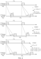
- the nth Sync message travels from a master to a slave experiences a fixed physical link (or propagation) delay of d f plus variable cumulative queuing (or stochastic) delay of q ⁇ f ( n ) (see Figure 3 ).
- the nth Delay_Req message sent from the slave 3 to the master 1 experiences a fixed delay of d r plus variable cumulative queuing delay of q r ( n ) .
- An asymmetric path exists when the fixed delay components and/or queuing delay components in both directions are unequal.
- the physical link asymmetry is manually calibrated and compensated for but the queue-induced asymmetry can be compensated for using a technique as described in the embodiments below.
- Equations 1 and 2 below are the two standard equations that describe the relationship between the timestamps exchanged between a master and a slave device in a time distribution network.
- T 1 , T 2 , T 3 and T 4 are the timestamps from the standard one- or two-step clock message exchange under IEEE 1588.8 PTP
- T 1 is the time of sending of a Sync message from the master to the slave according to the master clock
- T 2 is the time of receipt of the Sync message according to the slave clock
- T 3 is the time of sending of a Delay_Req message from the slave to the master according to the slave clock
- T 4 is the time of receipt of the Delay_Req message according to the master clock
- q f [ n ] and q r [ n ] are the forward and reverse queueing delays
- ⁇ 0 is the initial phase offset between the master and slave clocks
- ⁇ [ n ] is the slave clock skew with respect to master clock.
- D fsum ( n ) and D rsum ( n ) are defined as the summations of the forward and reverse displacements at time sample, n, respectively.
- D fsum ( n ) and D rsum ( n ) can be found over a window of, for example, N samples.
- MinD fsum q fmin ⁇ q f 0
- a similar procedure for the reverse direction means that an approximation to the reverse delay, minus an offset equal to the minimum of the estimated reverse delay, can also be tracked in that window, ( q ⁇ f ( n ) - q ⁇ rmin ).
- the phase estimation process employs equation (10) above to define the estimation process and produce the ⁇ E ( n ) estimates.
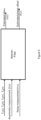
- the process is illustrated schematically in Figure 5 and employs a Kalman filter acting on the timestamps, the queuing asymmetry measurement and a noise measurement to produce an estimated skew and an estimated phase offset for the slave clock.
- the time stamps T 1 ( n ), T 2 ( n ), T 3 ( n ) and T 4 ( n ) are measured at the master and slave as per well-established existing practice.
- the values of ( q f ( n ) - q ⁇ fmin ) and ( q ⁇ r ( n ) - q ⁇ rmin ) are then generated as discussed above.
- the Kalman filter is a particular example of an estimation algorithm that can take advantage of equation (11), although other estimation techniques could equally be employed.
- the conventional Kalman filter measurement equation is modified to accommodate equation (11).
- the left-hand side of the above equation is the term Y n
- v n is the measurement noise
- the prediction and update phases operate as has been previously described, for example in US 9,112,628B .
- EWMA Exponentially Weighted Moving Average
- the average value of the noise variance on the forward path and the average value in the reverse direction both need to be found during steady state periods (i.e., when no change is occurring).
- the noise condition is deemed to have changed from the current category to a new category if the noise variance has changed sufficiently from the steady state average.
- a change detector can be implemented using two EWMA filters with different time constants, i.e., an EWMA filter with a long time constant which approximates the average value of a variable and one with a short time constant which is sensitive to changes in the variable.
- ⁇ Q and ⁇ S can be set as 60s and 600s respectively.
- the absolute value of e ( n ) (from (27)) for each input, var ⁇ q f ⁇ or var ⁇ q r ⁇ , is compared to the same threshold. If
- the threshold can be set a - priori if the conditions of the detection environment are known in advance or the threshold can be determined experimentally during operation (or a combination of both).
- e ( n ) the sign of e ( n ) from (27) defines whether the conditions have improved, or have deteriorated. A positive sign indicates worse conditions, i.e., higher noise. Thus if the value
- P 22 depends on the oscillator's stability (OCXO in the case of telecom applications), its variance, i.e., the variance of the P 22 term itself, is extremely low (almost non-existent). P 22 changes significantly only due to the external noise (and the primary external noise input is caused by forward and/or backward traffic load changes). This has been verified in realistic conditions using simulation.
- P 22 When external noise changes occur (i.e. the traffic load changes), P 22 reflects this by converging to a new stable level of error variance. Due to the filtering properties of the Kalman filter, this new level is, again, very stable (i.e., there is almost no variance). However, the magnitude of the new level will be very distinct from the previous state, provided there was a significant enough change in the noise conditions. Therefore, P 22 can be employed as input to (27) to provide reliable indications of changing load conditions. To determine whether the load on the forward or reverse direction has changed, the values var ⁇ q f ⁇ or var ⁇ q r ⁇ , from equations (22) and (23), are examined to see which one has changed significantly from the average.
- a computer system includes the hardware, software and data storage devices for embodying a system or carrying out a method according to the above described embodiments.
- a computer system may comprise a central processing unit (CPU), input means, output means and data storage.
- the computer system has a monitor to provide a visual output display.
- the data storage may comprise RAM, disk drives or other computer readable media.
- the computer system may include a plurality of computing devices connected by a network and able to communicate with each other over that network.
- the methods of the above embodiments may be provided as computer programs or as computer program products or computer readable media carrying a computer program which is arranged, when run on a computer, to perform the method(s) described above.
- computer readable media includes, without limitation, any non-transitory medium or media which can be read and accessed directly by a computer or computer system.
- the media can include, but are not limited to, magnetic storage media such as floppy discs, hard disc storage media and magnetic tape; optical storage media such as optical discs or CD-ROMs; electrical storage media such as memory, including RAM, ROM and flash memory; and hybrids and combinations of the above such as magnetic/optical storage media.
Landscapes
- Engineering & Computer Science (AREA)
- Computer Networks & Wireless Communication (AREA)
- Signal Processing (AREA)
- Synchronisation In Digital Transmission Systems (AREA)
- Computer And Data Communications (AREA)
- Data Exchanges In Wide-Area Networks (AREA)
Claims (13)
- Verfahren des Schätzens einer Phasenverschiebung einer lokalen Uhr (5) eines Zeit-Clients (3) im Vergleich zu einer Hauptuhr (4) eines Zeitservers (1), der mit dem Zeit-Client über ein Netzwerk (2) verbunden ist, wobei das Verfahren die folgenden Schritte beinhaltet:Senden von ersten Zeitnachrichten in eine Vorwärtsrichtung von dem Zeitserver (1) an den Zeit-Client (3) und zweiten Zeitnachrichten in eine Rückwärtsrichtung von dem Zeit-Client an den Zeitserver, und Aufzeichnen von Zeitstempeln, die die Zeit des Sendens und die Zeiten des Empfangs der Zeitnachrichten sind,Schätzen, für jede Nachricht in einem Fenster von vorbestimmter Länge, der Übertragungsverzögerung, die von der Nachricht erfahren wird;Bestimmen, aus den Schätzungen, einer minimalen geschätzten Verzögerung, die von Zeitnachrichten in der Vorwärtsrichtung in diesem Fenster erfahren wird, und einer minimalen geschätzten Verzögerung, die von Zeitnachrichten in der Rückwärtsrichtung in diesem Fenster erfahren wird;Bestimmen, für jede Nachricht in diesem Fenster, der Differenz zwischen der geschätzten Übertragungsverzögerung für diese Nachricht und der minimalen geschätzten Verzögerung für Nachrichten, die sich in die gleiche Richtung wie diese Nachricht bewegen;Bestimmen, aus den Differenzen, einer Warteschlangenasymmetriemessung für jeden Austausch von ersten und zweiten Zeitnachrichten in diesem Fenster;Schätzen der Phasenverschiebung der lokalen Uhr (5) zu einer Zeit in diesem Fenster unter Verwendung der Zeitstempel und der Warteschlangenasymmetriemessung als Eingaben an einen Schätzalgorithmus,Bestimmen, aus den Zeitstempeln, eines Vorwärtsverschiebungsfaktors, der die Differenz zwischen dem Intervall zwischen den Zeiten des Empfangs von aufeinanderfolgenden ersten Zeitnachrichten durch den Client und dem Intervall zwischen den Zeiten des Sendens der aufeinanderfolgenden ersten Nachrichten durch den Server ist;Bestimmen, aus den Zeitstempeln, eines Rückwärtsverschiebungsfaktors, der die Differenz zwischen dem Intervall zwischen den Zeiten des Empfangs von aufeinanderfolgenden zweiten Zeitnachrichten durch den Server und dem Intervall zwischen den Zeiten des Sendens der aufeinanderfolgenden zweiten Zeitnachrichten durch den Client ist;Aufrechterhalten einer laufenden Summe der Vorwärtsverschiebungsfaktoren über einen vorbestimmten Zeitraum;Aufrechterhalten einer laufenden Summe von Rückwärtsverschiebungsfaktoren über einen vorbestimmten Zeitraum; dadurch gekennzeichnet, dass das Verfahren ferner die folgenden Schritte umfasst:Bestimmen eines Rauschzustands des Vorwärtsübertragungspfads und eines Rauschzustands des Rückwärtsübertragungspfads über den vorbestimmten Zeitraum;wenn bestimmt ist, dass sowohl der Vorwärts- als auch der Rückwärtsübertragungspfad einen niedrigen Rauschzustand während des vorbestimmten Zeitraums aufweisen, Bestimmen eines Minimums der Summe von Vorwärtsverschiebungsfaktoren und eines Minimums der Summe von Rückwärtsverschiebungsfaktoren über diesen Zeitraum und Speichern der bestimmten Minima als Referenzminimalwerte; undwenn während eines zukünftigen Zeitraums bestimmt ist, dass einer aus dem Vorwärts- oder Rückwärtsübertragungspfad einen hohen Rauschzustand aufweist, während der andere Pfad einen niedrigen Rauschzustand aufweist, Verwenden der Referenzminimalwerte und des Minimums der Summe aus Verschiebungsfaktoren auf dem Pfad mit einem niedrigen Rauschzustand, um einen Minimalwert für die Summe aus Verschiebungsfaktoren auf dem Pfad mit einem hohen Rauschzustand zu schätzen.
- Verfahren nach Anspruch 1, wobei die Warteschlangenasymmetriemessung als Folgendes bestimmt ist:
 q̂f (n) eine Schätzung einer Warteschlangenverzögerung ist, die von der n-ten ersten Zeitnachricht erfahren wird;q̂r (n) eine Schätzung einer Warteschlangenverzögerung ist, die von der n-ten zweiten Zeitnachricht erfahren wird;q̂fmin der bestimmte Minimalwert von q̂f (n) in dem Fenster ist; undq̂rmin der bestimmte Minimalwert von q̂r (n) in dem Fenster ist.
 - Verfahren nach Anspruch 1 oder Anspruch 2, wobei der Schritt des Bestimmens der Warteschlangenasymmetriemessung Folgendes beinhaltet:
Berechnen der Warteschlangenasymmetriemessung aus den laufenden Summen. - Verfahren nach einem der Ansprüche 1 bis 3, wobei der Schätzalgorithmus ein Kalman-Filter ist, der die Messgleichung verwendet:
 T 1(n) der Zeitstempel ist, der durch den Server beim Senden einer n-ten ersten Zeitnachricht von dem Server an den Client aufgezeichnet wird;T 2(n) die Zeit des Empfangs ist, aufgezeichnet durch den Client beim Empfang der n-ten ersten Zeitnachricht;T 3(n) der Zeitstempel ist, aufgezeichnet durch den Client beim Senden einer n-ten zweiten Zeitnachricht von dem Client an den Server;T 4(n) die Zeit des Empfangs ist, aufgezeichnet durch den Server beim Empfang der n-ten zweiten Zeitnachricht;Q(n) die Warteschlangenasymmetriemessung ist;v n das Messrauschen ist; undθE (n) eine Schätzung des lokalen Uhren-Offsets ist.
 - Verfahren nach einem der Ansprüche 1-4, wobei der Schritt des Bestimmens eines Rauschzustands auf einem Übertragungspfad Folgendes beinhaltet:Berechnen, basierend auf den Zeitstempeln, einer Varianz einer Warteschlangenverzögerung auf diesem Pfad;Anwenden eines ersten gleitenden Durchschnitts mit einer ersten Zeitkonstante zur Varianz;Anwenden eines zweiten gleitenden Durchschnitts mit einer zweiten Zeitkonstante, die größer als die erste Zeitkonstante zur Varianz ist;Berechnen einer Differenz zwischen dem ersten und zweiten gleitenden Durchschnitt; undVergleichen der berechneten Differenz mit einem vorbestimmten Schwellenwert, um einen Rauschzustand auf dem Pfad zu bestimmen.
- Verfahren nach einem der Ansprüche 1-4, wobei der Schritt des Bestimmens eines Rauschzustands auf einem Übertragungspfad Folgendes beinhaltet:Bestimmen der Fehlervarianz-Kovarianz-Matrix
 aus einem Kalman-Filter, der in dem Schätzalgorithmus verwendet wird,wobei P 11 die Fehlervarianz der Phasenverschiebung ist, P 22 die Fehlervarianz des Versatzes (fraktionelles Frequenz-Offset) ist, und P 12 und P 21 die Fehlerkovarianz zwischen der Phasenverschiebung und dem Versatz darstellen.
 - Zeit-Client (3) mit einer lokalen Uhr (5) und einem Prozessor und verbunden über ein Netzwerk (2) mit einem Zeitserver (1) mit einer Hauptuhr (4), wobei der Zeit-Client für Folgendes angeordnet ist:Empfangen von ersten Zeitnachrichten in einer Vorwärtsrichtung von dem Zeitserver (1) an den Zeit-Client (3); und zweiten Zeitnachrichten in einer Rückwärtsrichtung von dem Zeit-Client (3) an den Zeitserver (1),Aufzeichnen von Zeitstempeln, die die Zeiten des Sendens und die Zeiten des Empfangs der Zeitnachrichten durch den Zeit-Client sind, undEmpfangen von Zeitstempeln, die die Zeiten des Sendens und die Zeiten des Empfangs der Zeitnachrichten durch den Zeitserver sind,wobei der Prozessor für Folgendes angeordnet ist:Schätzen, für jede Nachricht in einem Fenster von vorbestimmter Länge, der Übertragungsverzögerung, die von der Nachricht erfahren wird;Bestimmen, aus den Schätzungen, einer minimalen geschätzten Verzögerung, die von Zeitnachrichten in der Vorwärtsrichtung in diesem Fenster erfahren wird, und einer minimalen geschätzten Verzögerung, die von Zeitnachrichten in der Rückwärtsrichtung in diesem Fenster erfahren wird;Bestimmen, für jede Nachricht in diesem Fenster, der Differenz zwischen der geschätzten Übertragungsverzögerung für diese Nachricht und der minimalen geschätzten Verzögerung für Nachrichten, die sich in die gleiche Richtung wie diese Nachricht bewegen;Bestimmen, aus den Differenzen, einer Warteschlangenasymmetriemessung für jeden Austausch von ersten und zweiten Zeitnachrichten in diesem Fenster;Schätzen der Phasenverschiebung der lokalen Uhr zu einer Zeit in diesem Fenster unter Verwendung der Zeitstempel und der Warteschlangenasymmetriemessung als Eingaben an einen Schätzalgorithmus,Bestimmen, aus den Zeitstempeln, eines Vorwärtsverschiebungsfaktors, der die Differenz zwischen dem Intervall zwischen den Zeiten des Empfangs von aufeinanderfolgenden ersten Zeitnachrichten durch den Client und dem Intervall zwischen den Zeiten des Sendens der aufeinanderfolgenden ersten Nachrichten durch den Server ist;Bestimmen, aus den Zeitstempeln, eines Rückwärtsverschiebungsfaktors, der die Differenz zwischen dem Intervall zwischen den Zeiten des Empfangs von aufeinanderfolgenden zweiten Zeitnachrichten durch den Server und dem Intervall zwischen den Zeiten des Sendens der aufeinanderfolgenden zweiten Zeitnachrichten durch den Client ist;Aufrechterhalten einer laufenden Summe der Vorwärtsverschiebungsfaktoren über einen vorbestimmten Zeitraum;Aufrechterhalten einer laufenden Summe von Rückwärtsverschiebungsfaktoren über einen vorbestimmten Zeitraum; dadurch gekennzeichnet, dass der Prozessor ferner für Folgendes angeordnet ist:Bestimmen eines Rauschzustands des Vorwärtsübertragungspfads und eines Rauschzustands des Rückwärtsübertragungspfads über den vorbestimmten Zeitraum;wenn bestimmt ist, dass sowohl der Vorwärts- als auch der Rückwärtsübertragungspfad einen niedrigen Rauschzustand während des vorbestimmten Zeitraums aufweisen, Bestimmen eines Minimums der Summe von Vorwärtsverschiebungsfaktoren und eines Minimums der Summe von Rückwärtsverschiebungsfaktoren über diesen Zeitraum und Speichern der bestimmten Minima als Referenzminimalwerte; undwenn während eines zukünftigen Zeitraums bestimmt ist, dass einer aus dem Vorwärts- oder Rückwärtsübertragungspfad einen hohen Rauschzustand aufweist, während der andere Pfad einen niedrigen Rauschzustand aufweist, Verwenden der Referenzminimalwerte und des Minimums der Summe aus Verschiebungsfaktoren auf dem Pfad mit einem niedrigen Rauschzustand, um einen Minimalwert für die Summe aus Verschiebungsfaktoren auf dem Pfad mit einem hohen Rauschzustand zu schätzen.
- Zeit-Client nach Anspruch 7, wobei der Prozessor die Warteschlangenasymmetriemessung als Folgendes bestimmt:
 q̂f (n) eine Schätzung einer Warteschlangenverzögerung ist, die von der n-ten ersten Zeitnachricht erfahren wird;q̂r (n) eine Schätzung einer Warteschlangenverzögerung ist, die von der n-ten zweiten Zeitnachricht erfahren wird;q̂fmin der bestimmte Minimalwert von q̂f (n) in dem Fenster ist; undq̂rmin der bestimmte Minimalwert von q̂r (n) in dem Fenster ist.
 - Zeit-Client (3) nach Anspruch 7 oder Anspruch 8, wobei der Prozessor angeordnet ist, um die Warteschlangenasymmetriemessung durch Folgendes zu bestimmen:
Berechnen der Warteschlangenasymmetriemessung aus den laufenden Summen. - Zeit-Client (3) nach einem der Ansprüche 7 bis 9, wobei der Schätzalgorithmus, der durch den Prozessor verwendet wird, ein Kalman-Filter ist, der die Messgleichung verwendet:
 T 1(n) der Zeitstempel ist, der durch den Server beim Senden einer n-ten ersten Zeitnachricht von dem Server an den Client aufgezeichnet wird;T 2(n) die Zeit des Empfangs ist, aufgezeichnet durch den Client beim Empfang der n-ten ersten Zeitnachricht;T 3(n) der Zeitstempel ist, aufgezeichnet durch den Client beim Senden einer n-ten zweiten Zeitnachricht von dem Client an den Server;T 4(n) die Zeit des Empfangs ist, aufgezeichnet durch den Server beim Empfang der n-ten zweiten Zeitnachricht;Q(n) die Warteschlangenasymmetriemessung ist;vn das Messrauschen ist; undθE (n) eine Schätzung des lokalen Uhren-Offsets ist.
 - Zeit-Client (3) nach einem der Ansprüche 7-10, wobei der Prozessor angeordnet ist, um einen Rauschzustand auf einem Übertragungspfad durch Folgendes zu bestimmen:Berechnen, basierend auf den Zeitstempeln, einer Varianz einer Warteschlangenverzögerung auf diesem Pfad;Anwenden eines ersten gleitenden Durchschnitts mit einer ersten Zeitkonstante zur Varianz;Anwenden eines zweiten gleitenden Durchschnitts mit einer zweiten Zeitkonstante, die größer als die erste Zeitkonstante zur Varianz ist;Berechnen einer Differenz zwischen dem ersten und zweiten gleitenden Durchschnitt; undVergleichen der berechneten Differenz mit einem vorbestimmten Schwellenwert, um einen Rauschzustand auf dem Pfad zu bestimmen.
- Zeit-Client (3) nach einem der Ansprüche 7-10, wobei der Prozessor angeordnet ist, um einen Rauschzustand auf einem Übertragungspfad durch Folgendes zu bestimmen:Bestimmen der Fehlervarianz-Kovarianz-Matrix
 aus einem Kalman-Filter, der in dem Schätzalgorithmus verwendet wird,wobei P 11 die Fehlervarianz der Phasenverschiebung ist, P 22 die Fehlervarianz des Versatzes (fraktionelles Frequenz-Offset) ist, und P 12 und P 21 die Fehlerkovarianz zwischen der Phasenverschiebung und dem Versatz darstellen.
 - Vernetztes Zeitsystem mit Folgendem:einem Zeitserver (1) mit einer Hauptuhr (4);einem Zeit-Client (3) mit einer lokalen Uhr (5) und einem Prozessor undeinem Netzwerk (2), das den Zeitserver und den Zeit-Client verbindet,wobei der Zeitserver (1) für Folgendes angeordnet ist:Senden von ersten Zeitnachrichten in eine Vorwärtsrichtung an den Zeit-Client (3) und Empfangen von zweiten Zeitnachrichten, die in eine Rückwärtsrichtung von dem Zeit-Client gesendet werden,Aufzeichnen von Zeitstempeln, die die Zeiten des Sendens und die Zeiten des Empfangs der Zeitnachrichten durch den Zeitserver sind, undSenden von Zeitstempeln an den Zeit-Client,wobei der Zeit-Client (3) für Folgendes angeordnet ist:Empfangen der ersten Zeitnachrichten; und Senden der zweiten Zeitnachrichten an den Zeitserver (1),Aufzeichnen von Zeitstempeln, die die Zeiten des Sendens und die Zeiten des Empfangs der Zeitnachrichten durch den Zeit-Client sind, undEmpfangen von Zeitstempeln, die die Zeiten des Sendens und die Zeiten des Empfangs der Zeitnachrichten durch den Zeitserver sind,wobei der Prozessor für Folgendes angeordnet ist:Schätzen, für jede Nachricht in einem Fenster von vorbestimmter Länge, der Übertragungsverzögerung, die von der Nachricht erfahren wird;Bestimmen, aus den Schätzungen, einer minimalen geschätzten Verzögerung, die von Zeitnachrichten in der Vorwärtsrichtung in diesem Fenster erfahren wird, und einer minimalen geschätzten Verzögerung, die von Zeitnachrichten in der Rückwärtsrichtung in diesem Fenster erfahren wird;Bestimmen, für jede Nachricht in diesem Fenster, der Differenz zwischen der geschätzten Übertragungsverzögerung für diese Nachricht und der minimalen geschätzten Verzögerung für Nachrichten, die sich in die gleiche Richtung wie diese Nachricht bewegen;Bestimmen, aus den Differenzen, einer Warteschlangenasymmetriemessung für jeden Austausch von ersten und zweiten Zeitnachrichten in diesem Fenster;Schätzen der Phasenverschiebung der lokalen Uhr (5) zu einer Zeit in diesem Fenster unter Verwendung der Zeitstempel und der Warteschlangenasymmetriemessung als Eingaben an einen Schätzalgorithmus,Bestimmen, aus den Zeitstempeln, eines Vorwärtsverschiebungsfaktors, der die Differenz zwischen dem Intervall zwischen den Zeiten des Empfangs von aufeinanderfolgenden ersten Zeitnachrichten durch den Client und dem Intervall zwischen den Zeiten des Sendens der aufeinanderfolgenden ersten Nachrichten durch den Server ist;Bestimmen, aus den Zeitstempeln, eines Rückwärtsverschiebungsfaktors, der die Differenz zwischen dem Intervall zwischen den Zeiten des Empfangs von aufeinanderfolgenden zweiten Zeitnachrichten durch den Server und dem Intervall zwischen den Zeiten des Sendens der aufeinanderfolgenden zweiten Zeitnachrichten durch den Client ist;Aufrechterhalten einer laufenden Summe der Vorwärtsverschiebungsfaktoren über einen vorbestimmten Zeitraum;Aufrechterhalten einer laufenden Summe von Rückwärtsverschiebungsfaktoren über einen vorbestimmten Zeitraum; dadurch gekennzeichnet, dass der Prozessor ferner für Folgendes angeordnet ist:Bestimmen eines Rauschzustands des Vorwärtsübertragungspfads und eines Rauschzustands des Rückwärtsübertragungspfads über den vorbestimmten Zeitraum;wenn bestimmt ist, dass sowohl der Vorwärts- als auch der Rückwärtsübertragungspfad einen niedrigen Rauschzustand während des vorbestimmten Zeitraums aufweisen, Bestimmen eines Minimums der Summe von Vorwärtsverschiebungsfaktoren und eines Minimums der Summe von Rückwärtsverschiebungsfaktoren über diesen Zeitraum und Speichern der bestimmten Minima als Referenzminimalwerte; undwenn während eines zukünftigen Zeitraums bestimmt ist, dass einer aus dem Vorwärts- oder Rückwärtsübertragungspfad einen hohen Rauschzustand aufweist, während der andere Pfad einen niedrigen Rauschzustand aufweist, Verwenden der Referenzminimalwerte und des Minimums der Summe aus Verschiebungsfaktoren auf dem Pfad mit einem niedrigen Rauschzustand, um einen Minimalwert für die Summe aus Verschiebungsfaktoren auf dem Pfad mit einem hohen Rauschzustand zu schätzen.
Applications Claiming Priority (1)
| Application Number | Priority Date | Filing Date | Title |
|---|---|---|---|
| PCT/GB2016/053631 WO2018096304A1 (en) | 2016-11-22 | 2016-11-22 | Methods and systems for synchronization using delay asymmetry |
Publications (2)
| Publication Number | Publication Date |
|---|---|
| EP3545633A1 EP3545633A1 (de) | 2019-10-02 |
| EP3545633B1 true EP3545633B1 (de) | 2025-02-26 |
Family
ID=57482468
Family Applications (1)
| Application Number | Title | Priority Date | Filing Date |
|---|---|---|---|
| EP16805886.5A Active EP3545633B1 (de) | 2016-11-22 | 2016-11-22 | Verfahren und systeme zur synchronisierung mit verzögerungsasymmetrie |
Country Status (2)
| Country | Link |
|---|---|
| EP (1) | EP3545633B1 (de) |
| WO (1) | WO2018096304A1 (de) |
Families Citing this family (2)
| Publication number | Priority date | Publication date | Assignee | Title |
|---|---|---|---|---|
| IL279866B2 (en) * | 2020-12-30 | 2025-08-01 | Israel Aerospace Ind Ltd | Synchronization of a client device to a master clock |
| CN114124616B (zh) * | 2022-01-25 | 2022-05-27 | 浙江中控研究院有限公司 | 基于epa总线结构的时钟同步优化方法 |
Family Cites Families (2)
| Publication number | Priority date | Publication date | Assignee | Title |
|---|---|---|---|---|
| US9184861B2 (en) | 2013-10-01 | 2015-11-10 | Khalifa University of Science, Technology, and Research | Method and devices for synchronization |
| US9112628B2 (en) * | 2013-10-02 | 2015-08-18 | Khalifa University of Science, Technology, and Research | Method and devices for compensating for path asymmetry |
-
2016
- 2016-11-22 EP EP16805886.5A patent/EP3545633B1/de active Active
- 2016-11-22 WO PCT/GB2016/053631 patent/WO2018096304A1/en not_active Ceased
Also Published As
| Publication number | Publication date |
|---|---|
| EP3545633A1 (de) | 2019-10-02 |
| WO2018096304A1 (en) | 2018-05-31 |
Similar Documents
| Publication | Publication Date | Title |
|---|---|---|
| US10608764B2 (en) | Methods and systems for synchronization using delay asymmetry | |
| US9112628B2 (en) | Method and devices for compensating for path asymmetry | |
| US9671822B2 (en) | Method and devices for time transfer using end-to-end transparent clocks | |
| EP3053289B1 (de) | Verfahren und einrichtungen zur kompensation von wegasymmetrie | |
| US20180145863A1 (en) | Methods and systems for determining optimal packets | |
| US7876791B2 (en) | Synchronizing apparatus and method in packet network | |
| US7865760B2 (en) | Use of T4 timestamps to calculate clock offset and skew | |
| US11018789B2 (en) | End-to-end transparent clocks and methods of estimating skew in end-to-end transparent clocks | |
| US8644348B2 (en) | Method for generating a robust timing correction in timing transfer systems | |
| US7688865B2 (en) | Method and system for clock skew and offset estimation | |
| US10979164B2 (en) | Peer-to-peer transparent clocks and methods of estimating skew in peer-to-peer transparent clocks | |
| US9270607B2 (en) | Method and devices for packet selection | |
| KR20100016364A (ko) | 한 네트워크 구성요소의 클록을 다른 네트워크 구성요소의 클록과 동기화시키기 위한 방법 및 이를 위한 네트워크 구성요소 | |
| EP2893656B1 (de) | Verfahren und vorrichtung zur schätzung von uhrdifferenz und gangunterschied | |
| US10284414B2 (en) | Systems and methods for estimating skew | |
| EP3231110B1 (de) | Verfahren und vorrichtungen zur zeitübertragung mittel transparenten takten zwischen endpunkten | |
| US7822072B2 (en) | Clock filter dispersion | |
| EP3545633A1 (de) | Verfahren und systeme zur synchronisierung mit verzögerungsasymmetrie | |
| EP3231112B1 (de) | Verfahren und vorrichtungen zur zeitübertragung mittels gleichrangiger transparenter takte | |
| Khlifi et al. | Low-complexity offline and online clock skew estimation and removal | |
| EP3824573B1 (de) | Peer-to-peer-transparente uhren und verfahren zum schätzen von skew in peer-to-peer transparenten uhren | |
| EP3545634B1 (de) | Verfahren und systeme zum bestimmen optimaler nachrichten | |
| EP3469747B1 (de) | Verfahren und systeme zur schräglagenschätzung | |
| EP3080951B1 (de) | Paketauswahlverfahren und -vorrichtungen | |
| EP3824574B1 (de) | Transparente end-to-end-takte und verfahren zur schätzung des versatzes in transparenten end-to-end-takten |
Legal Events
| Date | Code | Title | Description |
|---|---|---|---|
| STAA | Information on the status of an ep patent application or granted ep patent |
Free format text: STATUS: UNKNOWN |
|
| STAA | Information on the status of an ep patent application or granted ep patent |
Free format text: STATUS: THE INTERNATIONAL PUBLICATION HAS BEEN MADE |
|
| PUAI | Public reference made under article 153(3) epc to a published international application that has entered the european phase |
Free format text: ORIGINAL CODE: 0009012 |
|
| STAA | Information on the status of an ep patent application or granted ep patent |
Free format text: STATUS: REQUEST FOR EXAMINATION WAS MADE |
|
| 17P | Request for examination filed |
Effective date: 20190610 |
|
| AK | Designated contracting states |
Kind code of ref document: A1 Designated state(s): AL AT BE BG CH CY CZ DE DK EE ES FI FR GB GR HR HU IE IS IT LI LT LU LV MC MK MT NL NO PL PT RO RS SE SI SK SM TR |
|
| AX | Request for extension of the european patent |
Extension state: BA ME |
|
| RIN1 | Information on inventor provided before grant (corrected) |
Inventor name: CHALOUPKA, ZDENEK Inventor name: BOYD, IVAN |
|
| DAV | Request for validation of the european patent (deleted) | ||
| DAX | Request for extension of the european patent (deleted) | ||
| STAA | Information on the status of an ep patent application or granted ep patent |
Free format text: STATUS: EXAMINATION IS IN PROGRESS |
|
| 17Q | First examination report despatched |
Effective date: 20211005 |
|
| GRAP | Despatch of communication of intention to grant a patent |
Free format text: ORIGINAL CODE: EPIDOSNIGR1 |
|
| STAA | Information on the status of an ep patent application or granted ep patent |
Free format text: STATUS: GRANT OF PATENT IS INTENDED |
|
| INTG | Intention to grant announced |
Effective date: 20240719 |
|
| GRAS | Grant fee paid |
Free format text: ORIGINAL CODE: EPIDOSNIGR3 |
|
| GRAA | (expected) grant |
Free format text: ORIGINAL CODE: 0009210 |
|
| STAA | Information on the status of an ep patent application or granted ep patent |
Free format text: STATUS: THE PATENT HAS BEEN GRANTED |
|
| AK | Designated contracting states |
Kind code of ref document: B1 Designated state(s): AL AT BE BG CH CY CZ DE DK EE ES FI FR GB GR HR HU IE IS IT LI LT LU LV MC MK MT NL NO PL PT RO RS SE SI SK SM TR |
|
| RAP3 | Party data changed (applicant data changed or rights of an application transferred) |
Owner name: EMIRATES TELECOMMUNICATIONS GROUP COMPANY PJSC Owner name: BRITISH TELECOMMUNICATIONS PUBLIC LIMITED COMPANY Owner name: KHALIFA UNIVERSITY OF SCIENCE AND TECHNOLOGY |
|
| REG | Reference to a national code |
Ref country code: GB Ref legal event code: FG4D |
|
| REG | Reference to a national code |
Ref country code: CH Ref legal event code: EP |
|
| REG | Reference to a national code |
Ref country code: DE Ref legal event code: R096 Ref document number: 602016091379 Country of ref document: DE |
|
| REG | Reference to a national code |
Ref country code: IE Ref legal event code: FG4D |
|
| REG | Reference to a national code |
Ref country code: NL Ref legal event code: MP Effective date: 20250226 |
|
| PG25 | Lapsed in a contracting state [announced via postgrant information from national office to epo] |
Ref country code: RS Free format text: LAPSE BECAUSE OF FAILURE TO SUBMIT A TRANSLATION OF THE DESCRIPTION OR TO PAY THE FEE WITHIN THE PRESCRIBED TIME-LIMIT Effective date: 20250526 |
|
| PG25 | Lapsed in a contracting state [announced via postgrant information from national office to epo] |
Ref country code: FI Free format text: LAPSE BECAUSE OF FAILURE TO SUBMIT A TRANSLATION OF THE DESCRIPTION OR TO PAY THE FEE WITHIN THE PRESCRIBED TIME-LIMIT Effective date: 20250226 |
|
| PG25 | Lapsed in a contracting state [announced via postgrant information from national office to epo] |
Ref country code: PL Free format text: LAPSE BECAUSE OF FAILURE TO SUBMIT A TRANSLATION OF THE DESCRIPTION OR TO PAY THE FEE WITHIN THE PRESCRIBED TIME-LIMIT Effective date: 20250226 |
|
| PG25 | Lapsed in a contracting state [announced via postgrant information from national office to epo] |
Ref country code: ES Free format text: LAPSE BECAUSE OF FAILURE TO SUBMIT A TRANSLATION OF THE DESCRIPTION OR TO PAY THE FEE WITHIN THE PRESCRIBED TIME-LIMIT Effective date: 20250226 |
|
| REG | Reference to a national code |
Ref country code: LT Ref legal event code: MG9D |
|
| PG25 | Lapsed in a contracting state [announced via postgrant information from national office to epo] |
Ref country code: IS Free format text: LAPSE BECAUSE OF FAILURE TO SUBMIT A TRANSLATION OF THE DESCRIPTION OR TO PAY THE FEE WITHIN THE PRESCRIBED TIME-LIMIT Effective date: 20250626 Ref country code: NO Free format text: LAPSE BECAUSE OF FAILURE TO SUBMIT A TRANSLATION OF THE DESCRIPTION OR TO PAY THE FEE WITHIN THE PRESCRIBED TIME-LIMIT Effective date: 20250526 |
|
| PG25 | Lapsed in a contracting state [announced via postgrant information from national office to epo] |
Ref country code: NL Free format text: LAPSE BECAUSE OF FAILURE TO SUBMIT A TRANSLATION OF THE DESCRIPTION OR TO PAY THE FEE WITHIN THE PRESCRIBED TIME-LIMIT Effective date: 20250226 |
|
| PG25 | Lapsed in a contracting state [announced via postgrant information from national office to epo] |
Ref country code: HR Free format text: LAPSE BECAUSE OF FAILURE TO SUBMIT A TRANSLATION OF THE DESCRIPTION OR TO PAY THE FEE WITHIN THE PRESCRIBED TIME-LIMIT Effective date: 20250226 |
|
| PG25 | Lapsed in a contracting state [announced via postgrant information from national office to epo] |
Ref country code: LV Free format text: LAPSE BECAUSE OF FAILURE TO SUBMIT A TRANSLATION OF THE DESCRIPTION OR TO PAY THE FEE WITHIN THE PRESCRIBED TIME-LIMIT Effective date: 20250226 Ref country code: PT Free format text: LAPSE BECAUSE OF FAILURE TO SUBMIT A TRANSLATION OF THE DESCRIPTION OR TO PAY THE FEE WITHIN THE PRESCRIBED TIME-LIMIT Effective date: 20250626 |
|
| PG25 | Lapsed in a contracting state [announced via postgrant information from national office to epo] |
Ref country code: BG Free format text: LAPSE BECAUSE OF FAILURE TO SUBMIT A TRANSLATION OF THE DESCRIPTION OR TO PAY THE FEE WITHIN THE PRESCRIBED TIME-LIMIT Effective date: 20250226 Ref country code: GR Free format text: LAPSE BECAUSE OF FAILURE TO SUBMIT A TRANSLATION OF THE DESCRIPTION OR TO PAY THE FEE WITHIN THE PRESCRIBED TIME-LIMIT Effective date: 20250527 |
|
| REG | Reference to a national code |
Ref country code: AT Ref legal event code: MK05 Ref document number: 1771708 Country of ref document: AT Kind code of ref document: T Effective date: 20250226 |
|
| PG25 | Lapsed in a contracting state [announced via postgrant information from national office to epo] |
Ref country code: SE Free format text: LAPSE BECAUSE OF FAILURE TO SUBMIT A TRANSLATION OF THE DESCRIPTION OR TO PAY THE FEE WITHIN THE PRESCRIBED TIME-LIMIT Effective date: 20250226 |
|
| PG25 | Lapsed in a contracting state [announced via postgrant information from national office to epo] |
Ref country code: SM Free format text: LAPSE BECAUSE OF FAILURE TO SUBMIT A TRANSLATION OF THE DESCRIPTION OR TO PAY THE FEE WITHIN THE PRESCRIBED TIME-LIMIT Effective date: 20250226 |
|
| PG25 | Lapsed in a contracting state [announced via postgrant information from national office to epo] |
Ref country code: DK Free format text: LAPSE BECAUSE OF FAILURE TO SUBMIT A TRANSLATION OF THE DESCRIPTION OR TO PAY THE FEE WITHIN THE PRESCRIBED TIME-LIMIT Effective date: 20250226 |
|
| PG25 | Lapsed in a contracting state [announced via postgrant information from national office to epo] |
Ref country code: IT Free format text: LAPSE BECAUSE OF FAILURE TO SUBMIT A TRANSLATION OF THE DESCRIPTION OR TO PAY THE FEE WITHIN THE PRESCRIBED TIME-LIMIT Effective date: 20250226 |
|
| PG25 | Lapsed in a contracting state [announced via postgrant information from national office to epo] |
Ref country code: AT Free format text: LAPSE BECAUSE OF FAILURE TO SUBMIT A TRANSLATION OF THE DESCRIPTION OR TO PAY THE FEE WITHIN THE PRESCRIBED TIME-LIMIT Effective date: 20250226 |
|
| PG25 | Lapsed in a contracting state [announced via postgrant information from national office to epo] |
Ref country code: EE Free format text: LAPSE BECAUSE OF FAILURE TO SUBMIT A TRANSLATION OF THE DESCRIPTION OR TO PAY THE FEE WITHIN THE PRESCRIBED TIME-LIMIT Effective date: 20250226 Ref country code: CZ Free format text: LAPSE BECAUSE OF FAILURE TO SUBMIT A TRANSLATION OF THE DESCRIPTION OR TO PAY THE FEE WITHIN THE PRESCRIBED TIME-LIMIT Effective date: 20250226 |
|
| PG25 | Lapsed in a contracting state [announced via postgrant information from national office to epo] |
Ref country code: RO Free format text: LAPSE BECAUSE OF FAILURE TO SUBMIT A TRANSLATION OF THE DESCRIPTION OR TO PAY THE FEE WITHIN THE PRESCRIBED TIME-LIMIT Effective date: 20250226 |
|
| PG25 | Lapsed in a contracting state [announced via postgrant information from national office to epo] |
Ref country code: SK Free format text: LAPSE BECAUSE OF FAILURE TO SUBMIT A TRANSLATION OF THE DESCRIPTION OR TO PAY THE FEE WITHIN THE PRESCRIBED TIME-LIMIT Effective date: 20250226 |
|
| REG | Reference to a national code |
Ref country code: DE Ref legal event code: R097 Ref document number: 602016091379 Country of ref document: DE |
|
| PLBE | No opposition filed within time limit |
Free format text: ORIGINAL CODE: 0009261 |
|
| STAA | Information on the status of an ep patent application or granted ep patent |
Free format text: STATUS: NO OPPOSITION FILED WITHIN TIME LIMIT |
|
| PGFP | Annual fee paid to national office [announced via postgrant information from national office to epo] |
Ref country code: DE Payment date: 20251126 Year of fee payment: 10 |
|
| PGFP | Annual fee paid to national office [announced via postgrant information from national office to epo] |
Ref country code: GB Payment date: 20251127 Year of fee payment: 10 |
|
| PGFP | Annual fee paid to national office [announced via postgrant information from national office to epo] |
Ref country code: FR Payment date: 20251124 Year of fee payment: 10 |
|
| 26N | No opposition filed |
Effective date: 20251127 |