EP2385462B1 - Mobile terminal and method of controlling the same - Google Patents
Mobile terminal and method of controlling the same Download PDFInfo
- Publication number
- EP2385462B1 EP2385462B1 EP11003022.8A EP11003022A EP2385462B1 EP 2385462 B1 EP2385462 B1 EP 2385462B1 EP 11003022 A EP11003022 A EP 11003022A EP 2385462 B1 EP2385462 B1 EP 2385462B1
- Authority
- EP
- European Patent Office
- Prior art keywords
- contents
- mobile terminal
- display
- widgets
- electronic devices
- Prior art date
- Legal status (The legal status is an assumption and is not a legal conclusion. Google has not performed a legal analysis and makes no representation as to the accuracy of the status listed.)
- Not-in-force
Links
- 238000000034 method Methods 0.000 title claims description 36
- 238000004891 communication Methods 0.000 claims description 35
- 230000004044 response Effects 0.000 claims description 16
- 230000000153 supplemental effect Effects 0.000 claims 2
- 230000006870 function Effects 0.000 description 17
- 230000000694 effects Effects 0.000 description 12
- 230000005540 biological transmission Effects 0.000 description 11
- 230000008859 change Effects 0.000 description 9
- 230000008569 process Effects 0.000 description 8
- 230000005236 sound signal Effects 0.000 description 8
- 238000010295 mobile communication Methods 0.000 description 7
- 238000010586 diagram Methods 0.000 description 4
- 230000001133 acceleration Effects 0.000 description 3
- 230000009471 action Effects 0.000 description 3
- 238000013459 approach Methods 0.000 description 3
- 239000004973 liquid crystal related substance Substances 0.000 description 3
- 238000007726 management method Methods 0.000 description 3
- 238000012986 modification Methods 0.000 description 3
- 230000004048 modification Effects 0.000 description 3
- 238000012545 processing Methods 0.000 description 3
- 230000000007 visual effect Effects 0.000 description 3
- 230000001413 cellular effect Effects 0.000 description 2
- 238000013500 data storage Methods 0.000 description 2
- 238000001514 detection method Methods 0.000 description 2
- 230000003287 optical effect Effects 0.000 description 2
- 229910001220 stainless steel Inorganic materials 0.000 description 2
- 239000010935 stainless steel Substances 0.000 description 2
- 239000010936 titanium Substances 0.000 description 2
- 101150012579 ADSL gene Proteins 0.000 description 1
- 241000251468 Actinopterygii Species 0.000 description 1
- 102100020775 Adenylosuccinate lyase Human genes 0.000 description 1
- 108700040193 Adenylosuccinate lyases Proteins 0.000 description 1
- 241000124032 Paracheirodon axelrodi Species 0.000 description 1
- RTAQQCXQSZGOHL-UHFFFAOYSA-N Titanium Chemical compound [Ti] RTAQQCXQSZGOHL-UHFFFAOYSA-N 0.000 description 1
- 238000003491 array Methods 0.000 description 1
- 230000008901 benefit Effects 0.000 description 1
- 238000006243 chemical reaction Methods 0.000 description 1
- 238000004590 computer program Methods 0.000 description 1
- 230000005684 electric field Effects 0.000 description 1
- 239000010408 film Substances 0.000 description 1
- 238000001746 injection moulding Methods 0.000 description 1
- 230000003155 kinesthetic effect Effects 0.000 description 1
- 239000007769 metal material Substances 0.000 description 1
- 238000003909 pattern recognition Methods 0.000 description 1
- 239000004033 plastic Substances 0.000 description 1
- 229920003023 plastic Polymers 0.000 description 1
- 230000005855 radiation Effects 0.000 description 1
- 238000009877 rendering Methods 0.000 description 1
- 238000013468 resource allocation Methods 0.000 description 1
- 230000011664 signaling Effects 0.000 description 1
- 238000001228 spectrum Methods 0.000 description 1
- 230000003068 static effect Effects 0.000 description 1
- 230000001360 synchronised effect Effects 0.000 description 1
- 239000010409 thin film Substances 0.000 description 1
- 229910052719 titanium Inorganic materials 0.000 description 1
- 238000012546 transfer Methods 0.000 description 1
Images


Classifications
-
- H—ELECTRICITY
- H04—ELECTRIC COMMUNICATION TECHNIQUE
- H04B—TRANSMISSION
- H04B1/00—Details of transmission systems, not covered by a single one of groups H04B3/00 - H04B13/00; Details of transmission systems not characterised by the medium used for transmission
- H04B1/38—Transceivers, i.e. devices in which transmitter and receiver form a structural unit and in which at least one part is used for functions of transmitting and receiving
- H04B1/40—Circuits
-
- G—PHYSICS
- G06—COMPUTING; CALCULATING OR COUNTING
- G06F—ELECTRIC DIGITAL DATA PROCESSING
- G06F9/00—Arrangements for program control, e.g. control units
- G06F9/06—Arrangements for program control, e.g. control units using stored programs, i.e. using an internal store of processing equipment to receive or retain programs
- G06F9/44—Arrangements for executing specific programs
- G06F9/451—Execution arrangements for user interfaces
- G06F9/452—Remote windowing, e.g. X-Window System, desktop virtualisation
-
- G—PHYSICS
- G06—COMPUTING; CALCULATING OR COUNTING
- G06F—ELECTRIC DIGITAL DATA PROCESSING
- G06F16/00—Information retrieval; Database structures therefor; File system structures therefor
- G06F16/90—Details of database functions independent of the retrieved data types
- G06F16/95—Retrieval from the web
- G06F16/957—Browsing optimisation, e.g. caching or content distillation
- G06F16/9577—Optimising the visualization of content, e.g. distillation of HTML documents
-
- G—PHYSICS
- G06—COMPUTING; CALCULATING OR COUNTING
- G06F—ELECTRIC DIGITAL DATA PROCESSING
- G06F21/00—Security arrangements for protecting computers, components thereof, programs or data against unauthorised activity
- G06F21/10—Protecting distributed programs or content, e.g. vending or licensing of copyrighted material ; Digital rights management [DRM]
Definitions
- the present invention relates to a mobile terminal and a control method thereof and, more particularly, to a mobile terminal and a control method thereof to display widgets reflecting contents information received from other electronic devices.
- the terminals As the functions of terminals, such as personal computers, laptop computers, cellular phones and the like, are diversified, the terminals are constructed in the form of a multimedia player having multiple functions such as capturing pictures or moving images, playing music, moving image files and games, and receiving broadcasting programs.
- Terminals can be divided into mobile terminals and stationary terminals.
- the mobile terminals can be classified into handheld terminals and vehicle mountable terminals according to their modes of mobility.
- Document WO 01/18691 A2 discloses a method for efficiently transferring data between a client and a server, including the steps of: providing an application program; providing an application-independent client process effecting a plurality of client states; providing an application-independent server process effecting a plurality of server states; transferring data from the server process to the client process in response to an application program; and updating at least one client state in response to the transferred data.
- a related apparatus is also disclosed.
- a variety of recent terminals including mobile terminals provide more complex and various functions.
- a structural part and/or a software part of the terminal need to be improved.
- An aspect of this document is to provide a mobile terminal and a control method thereof to display widgets reflecting contents information received from other electronic devices.
- a mobile terminal is provided in accordance with claim 1.
- a method of controlling a mobile terminal is provided in accordance with claim 11.
- the mobile terminal described in the specification may include a cellular phone, a smart phone, a laptop computer, a digital broadcasting terminal, personal digital assistants (PDA), a portable multimedia player (PMP), a navigation system and so on.
- PDA personal digital assistants
- PMP portable multimedia player
- FIG. 1 is a block diagram of a mobile terminal 100 according to an embodiment of the present invention. Other embodiments, configurations and arrangements may also be provided for the present invention.
- the mobile terminal 100 may include a wireless communication unit 110, an audio/video (A/V) input unit 120, a user input unit 130, a sensing unit 140, an output unit 150, a memory 160, an interface unit 170, a controller 180, and a power supply 190. Not all of the components shown in FIG. 1 may be essential parts and the number of components included in the mobile terminal 100 may be varied. The components of the mobile terminal 100 will now be described.
- A/V audio/video
- the wireless communication unit 110 may include at least one module that enables wireless communication between the mobile terminal 100 and a wireless communication system or between the mobile terminal 100 and a network in which the mobile terminal 100 is located.
- the wireless communication unit 110 may include a broadcast receiving module 111, a mobile communication module 112, a wireless Internet module 113, a local area or short-range communication module 114, and a position-location module 115.
- the broadcast receiving module 111 may receive broadcast signals and/or broadcast related information from an external broadcast management server through a broadcast channel.
- the broadcast channel may include a satellite channel and a terrestrial channel
- the broadcast management server may be a server that generates and transmits broadcast signals and/or broadcast related information or a server that receives previously created broadcast signals and/or broadcast related information and transmits the broadcast signals and/or broadcast related information to a terminal.
- the broadcast signals may include not only TV broadcast signals, radio broadcast signals, and data broadcast signals, but also signals in the form of a combination of a TV broadcast signal and a radio broadcast signal.
- the broadcast related information may be information on a broadcast channel, a broadcast program or a broadcast service provider, and may be provided even through a mobile communication network. In the latter case, the broadcast related information may be received by the mobile communication module 112.
- the broadcast related information may exist in various forms.
- the broadcast related information may exist in the form of an electronic program guide (EPG) of a digital multimedia broadcasting (DMB) system or in the form of an electronic service guide (ESG) of a digital video broadcast-handheld (DVB-H) system.
- EPG electronic program guide
- ESG electronic service guide
- DMB digital multimedia broadcasting
- DVB-H digital video broadcast-handheld
- the broadcast receiving module 111 may receive broadcast signals using various broadcasting systems. More particularly, the broadcast receiving module 111 may receive digital broadcast signals using digital broadcasting systems such as a digital multimedia broadcasting-terrestrial (DMB-T) system, a digital multimedia broadcasting-satellite (DMB-S) system, a media forward link only (MediaFLO) system, a DVB-H and integrated services digital broadcast-terrestrial (ISDB-T) systems.
- DMB-T digital multimedia broadcasting-terrestrial
- DMB-S digital multimedia broadcasting-satellite
- MediaFLO media forward link only
- ISDB-T integrated services digital broadcast-terrestrial
- the broadcast receiving module 111 may receive signals from broadcasting systems providing broadcast signals other than the above-described digital broadcast systems.
- the broadcast signals and/or broadcast related information received through the broadcast receiving module 111 may be stored in the memory 160.
- the mobile communication module 112 may transmit/receive a radio signal to/from at least one of a base station, an external terminal and a server on a mobile communication network.
- the radio signal may include a voice call signal, a video telephony call signal or data in various forms according to transmission and reception of text/multimedia messages.
- the wireless Internet module 113 may correspond to a module for wireless Internet access and may be included in the mobile terminal 100 or may be externally attached to the mobile terminal 100.
- Wireless LAN WLAN or Wi-Fi
- Wibro wireless broadband
- Wimax world interoperability for microwave access
- HSDPA high speed downlink packet access
- the short-range communication module 114 may correspond to a module for local area communication. Further, Bluetooth®, radio frequency identification (RFID), infrared data association (IrDA), ultra wideband (UWB) and/or ZigBee® may be used as a local area communication technique.
- RFID radio frequency identification
- IrDA infrared data association
- UWB ultra wideband
- ZigBee® ZigBee®
- the position-location module 115 may confirm or obtain the position of the mobile terminal 100.
- the position-location module 115 may obtain position information by using a global navigation satellite system (GNSS).
- GNSS global navigation satellite system
- the GNSS is a terminology describing a radio navigation satellite system that revolves around the earth and transmits reference signals to predetermined types of radio navigation receivers such that the radio navigation receivers can determine their positions on the earth's surface or near the earth's surface.
- the GNSS may include a global positioning system (GPS) of the United States, Galileo of Europe, a global orbiting navigational satellite system (GLONASS) of Russia, COMPASS of China, and a quasi-zenith satellite system (QZSS) of Japan among others.
- GPS global positioning system
- Galileo Galileo of Europe
- GLONASS global orbiting navigational satellite system
- QZSS quasi-zenith satellite system
- a global positioning system (GPS) module is a representative example of the position-location module 115.
- the GPS module may calculate information on distances between one point or object and at least three satellites and information on a time when the distance information is measured and apply trigonometry to the obtained distance information to obtain three-dimensional position information on the point or object according to latitude, longitude and altitude at a predetermined time.
- a method of calculating position and time information using three satellites and correcting the calculated position and time information using another satellite may also be used.
- the GPS module may continuously calculate the current position in real time and calculate velocity information using the location or position information.
- the A/V input unit 120 may input an audio signal or a video signal and include a camera 121 and a microphone 122.
- the camera 121 may process image frames of still images or moving images obtained by an image sensor in a video telephony mode or a photographing mode.
- the processed image frames may be displayed on a display module 151 which may be a touch screen.
- the image frames processed by the camera 121 may be stored in the memory 160 or may be transmitted to an external device through the wireless communication unit 110.
- the mobile terminal 100 may also include at least two cameras 121.
- the microphone 122 may receive an external audio signal in a call mode, a recording mode or a speech recognition mode and process the received audio signal into electric audio data. The audio data may then be converted into a form that can be transmitted to a mobile communication base station through the mobile communication module 112 and output in the call mode.
- the microphone 122 may employ various noise removal algorithms (or noise canceling algorithm) for removing or reducing noise generated when the external audio signal is received.
- the user input unit 130 may receive input data for controlling operation of the mobile terminal 100 from a user.
- the user input unit 130 may include a keypad, a dome switch, a touch pad (constant voltage/capacitance), a jog wheel, a jog switch and so on.
- the sensing unit 140 may sense a current state of the mobile terminal 100, such as an open/close state of the mobile terminal 100, a position of the mobile terminal 100, whether a user touches the mobile terminal 100, a direction of the mobile terminal 100, and acceleration/deceleration of the mobile terminal 100, and generate a sensing signal for controlling operation of the mobile terminal 100.
- a current state of the mobile terminal 100 such as an open/close state of the mobile terminal 100, a position of the mobile terminal 100, whether a user touches the mobile terminal 100, a direction of the mobile terminal 100, and acceleration/deceleration of the mobile terminal 100
- the sensing unit 140 may sense whether the slide phone is opened or closed. Further, the sensing unit 140 may sense whether the power supply 190 supplies power and/or whether the interface unit 170 is connected to an external device.
- the sensing unit 140 may also include a proximity sensor 141 (not shown in the drawings).
- the output unit 150 may generate visual, auditory and/or tactile output and may include the display module 151, an audio output module 152, an alarm unit 153 and a haptic module 154.
- the display module 151 may display information processed by the mobile terminal 100.
- the display module 151 may display a user interface (UI) or a graphic user interface (GUI) related to a telephone call when the mobile terminal 100 is in the call mode.
- the display module 151 may also display a captured and/or received image, a UI or a GUI when the mobile terminal 100 is in the video telephony mode or the photographing mode.
- the display module 151 may include at least one of a liquid crystal display, a thin film transistor liquid crystal display, an organic light-emitting diode display, a flexible display and a three-dimensional display. Some of these displays may be of a transparent type or a light transmissive type. That is, the display module 151 may include a transparent display module.
- the transparent display module may include a transparent liquid crystal display.
- the rear structure of the display module 151 may also be of a light transmissive type. Accordingly, a user may see an object located behind the body of the mobile terminal 100 through the transparent area of the body of the mobile terminal 100 that is occupied by the display module 151.
- the mobile terminal 100 may also include at least two display modules 151.
- the mobile terminal 100 may include a plurality of display modules 151 that are arranged on a single face at a predetermined distance or integrated displays.
- the plurality of display modules 151 may also be arranged on different sides.
- the display module 151 and a sensor sensing touch form a layered structure that is referred to as a touch screen
- the display module 151 may be used as an input device in addition to an output device.
- the touch sensor may be in the form of a touch film, a touch sheet, and a touch pad, for example.
- the touch sensor may convert a variation in pressure applied to a specific portion of the display module 151 or a variation in capacitance generated at a specific portion of the display module 151 into an electric input signal.
- the touch sensor may sense pressure of touch as well as position and area of the touch.
- a signal corresponding to the touch input may be transmitted to a touch controller.
- the touch controller may then process the signal and transmit data corresponding to the processed signal to the controller 180. Accordingly, the controller 180 may detect a touched portion of the display module 151.
- the proximity sensor 141 of the sensing unit 140 may be located in an internal region of the mobile terminal 100, surrounded by the touch screen, or near the touch screen.
- the proximity sensor 141 may sense an object approaching a predetermined sensing face or an object located near the proximity sensor using an electromagnetic force or infrared rays without having mechanical contact.
- the proximity sensor 141 may have a lifetime longer than a contact sensor and may thus have a wide application in the mobile terminal 100.
- the proximity sensor 141 may include a transmission type photo-electric sensor, a direct reflection type photo-electric sensor, a mirror reflection type photo-electric sensor, a high-frequency oscillating proximity sensor, a capacitive proximity sensor, a magnetic proximity sensor, and/or an infrared proximity sensor.
- a capacitive touch screen may be constructed such that proximity of a pointer is detected through a variation in an electric field according to the proximity of the pointer.
- the touch screen (touch sensor) may be classified as a proximity sensor 141.
- an action of the pointer approaching the touch screen without actually touching the touch screen may be referred to as a "proximity touch” and an action of bringing the pointer into contact with the touch screen may be referred to as a "contact touch.”
- the proximity touch point of the pointer on the touch screen may correspond to a point of the touch screen at which the pointer is perpendicular to the touch screen.
- the proximity sensor 141 may sense the proximity touch and a proximity touch pattern (e.g., a proximity touch distance, a proximity touch direction, a proximity touch velocity, a proximity touch time, a proximity touch position, a proximity touch moving state, and the like). Information corresponding to the sensed proximity touch action and proximity touch pattern may then be displayed on the touch screen.
- a proximity touch pattern e.g., a proximity touch distance, a proximity touch direction, a proximity touch velocity, a proximity touch time, a proximity touch position, a proximity touch moving state, and the like.
- the audio output module 152 may output audio data received from the wireless communication unit 110 or stored in the memory 160 in a call signal receiving mode, a telephone call mode or a recording mode, a speech recognition mode and a broadcasting receiving mode.
- the audio output module 152 may output audio signals related to functions, such as a call signal incoming tone and a message incoming tone, performed in the mobile terminal 100.
- the audio output module 152 may include a receiver, a speaker, a buzzer, and the like.
- the audio output module 152 may output sounds through an earphone jack. The user may hear the sounds by connecting an earphone to the earphone jack.
- the alarm unit 153 may output a signal for indicating generation of an event of the mobile terminal 100. For example, alarms may be generated when receiving a call signal, receiving a message, inputting a key signal, or inputting touch.
- the alarm unit 153 may also output signals in forms different from video signals or audio signals, for example, a signal for indicating generation of an event through vibration.
- the video signals or the audio signals may also be output through the display unit 151 or the audio output module 152.
- the haptic module 154 may generate various haptic effects that the user can feel.
- One example of the haptic effects is vibration.
- the intensity and/or pattern of vibration generated by the haptic module 154 may also be controlled. For example, different vibrations may be combined and output or may be sequentially output.
- the haptic module 154 may generate a variety of haptic effects including an effect of stimulus according to an arrangement of pins vertically moving against a contact skin surface, an effect of stimulus according to a jet force or sucking force of air through a jet hole or a sucking hole, an effect of stimulus of rubbing the skin, an effect of stimulus according to contact of an electrode, an effect of stimulus using an electrostatic force, and an effect according to a reproduction of cold and warmth using an element capable of absorbing or radiating heat in addition to vibrations.
- the haptic module 154 may not only transmit haptic effects through direct contact but may also allow the user to feel haptic effects through a kinesthetic sense of the user's fingers or arms.
- the mobile terminal 100 may also include a plurality of haptic modules 154.
- the memory 160 may store a program for operation of the controller 180 and temporarily store input/output data such as a phone book, messages, still images, and/or moving images.
- the memory 160 may also store data about vibrations and sounds in various patterns that are output from when a touch input is applied to the touch screen.
- the memory 160 may include at least a flash memory, a hard disk type memory, a multimedia card micro type memory, a card type memory, such as SD or XD memory, a random access memory (RAM), a static RAM (SRAM), a read-only memory (ROM), an electrically erasable programmable ROM (EEPROM), a programmable ROM (PROM) magnetic memory, a magnetic disk or an optical disk.
- the mobile terminal 100 may also operate in relation to a web storage performing the storing function of the memory 160 on the Internet.
- the interface unit 170 may serve as a path to external devices connected to the mobile terminal 100.
- the interface unit 170 may receive data from the external devices or power and transmit the data or power to internal components of the mobile terminal 100 or transmit data of the mobile terminal 100 to the external devices.
- the interface unit 170 may include a wired/wireless headset port, an external charger port, a wired/wireless data port, a memory card port, a port for connecting a device having a user identification module, an audio I/O port, a video I/O port, and/or an earphone port.
- the interface unit 170 may also interface with a user identification module that is a chip that stores information for authenticating authority to use the mobile terminal 100.
- the user identification module may be a user identify module (UIM), a subscriber identify module (SIM) and a universal subscriber identify module (USIM).
- An identification device including the user identification module may also be manufactured in the form of a smart card. Accordingly, the identification device may be connected to the mobile terminal 100 through a port of the interface unit 170.
- the interface unit 170 may also be a path through which power from an external cradle is provided to the mobile terminal 100 when the mobile terminal 100 is connected to the external cradle or a path through which various command signals input by the user through the cradle are transmitted to the mobile terminal 100.
- the various command signals or power input from the cradle may be used as signals for confirming whether the mobile terminal 100 is correctly set in the cradle.
- the controller 180 may control overall operations of the mobile terminal 100.
- the controller 180 may perform control and processing for voice communication, data communication and/or video telephony.
- the controller 180 may also include a multimedia module 181 for playing multimedia.
- the multimedia module 181 may be included in the controller 180 as shown in FIG. 1 or may be separated from the controller 180.
- the controller 180 may perform a pattern recognition process capable of recognizing handwriting input or picture-drawing input applied to the touch screen as characters or images.
- the power supply 190 may receive external power and internal power and provide power required for operations of the components of the mobile terminal 100 under control of the controller 180.
- embodiments of the present disclosure may be implemented using at least one of application specific integrated circuits (ASICs), digital signal processors (DSPs), digital signal processing devices (DSPDs), programmable logic devices (PLDs), field programmable gate arrays (FPGAs), processors, controllers, micro-controllers, microprocessors, and/or electrical units for executing functions.
- ASICs application specific integrated circuits
- DSPs digital signal processors
- DSPDs digital signal processing devices
- PLDs programmable logic devices
- FPGAs field programmable gate arrays
- processors controllers, micro-controllers, microprocessors, and/or electrical units for executing functions.
- controller 180 may be implemented by the controller 180.
- embodiments such as procedures or functions may be implemented with a separate software module executing at least one function or operation.
- Software codes may be implemented according to a software application written in an appropriate software language. The software codes may be stored in the memory 160 and executed by the controller 180.
- FIG. 2A is a front perspective view of a mobile terminal or a handheld terminal 100 according to an embodiment of the present invention.
- the handheld terminal 100 has a bar type terminal body.
- the present invention is not limited to a bar type terminal and can be applied to terminals of various types including a slide type, a folder type, a swing type and a swivel type terminal having at least two bodies that are relatively movably combined.
- the terminal body includes a case (a casing, a housing, or a cover) forming the exterior of the terminal 100.
- the case can be divided into a front case 101 and a rear case 102.
- Various electronic components are arranged in the space formed between the front case 101 and the rear case 102.
- At least one middle case can be additionally arranged between the front case 101 and the rear case 102.
- the cases can be formed of plastics through injection molding or made of a metal material such as stainless steel (STS) or titanium (Ti).
- STS stainless steel
- Ti titanium
- the display module 151, the audio output module 152, the camera 121, the user input unit 130 including operating units 131 and 132, the microphone 122 and the interface unit 170 can be arranged in the terminal body, specifically, in the front case 101.
- the display module 151 occupies most part of the main face of the front case 101.
- the audio output module 152 and the camera 121 are arranged in a region in proximity to one of both ends of the display module 151 and the operating unit 131 and the microphone 122 are located in a region in proximity to the other end of the display unit 151.
- the operating unit 132 and the interface unit 170 are arranged on the sides of the front case 101 and the rear case 102.
- the user input unit 130 is operated to receive commands for controlling the operation of the handheld terminal 100 and can include a plurality of operating units 131 and 132.
- the operating units 131 and 132 can be referred to as manipulating portions and employ any tactile manner in which a user operates the operating units 131 and 132 while having tactile feeling.
- First and second operating units 131 and 132 can receive various inputs.
- the first operating unit 131 receives commands such as start, end and scroll and the second operating unit 132 receives commands such as control of the volume of sound output from the audio output module 152 or conversion of the display module 151 to a touch recognition mode.
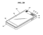
- FIG. 2B is a rear perspective view of the handheld terminal shown in FIG. 2A according to an embodiment of the present invention.
- a camera 121' can be additionally attached to the rear side of the terminal body, that is, the rear case 102.
- the camera 121' has a photographing direction opposite to that of the camera 121 shown in FIG. 2A and can have pixels different from those of the camera 121 shown in FIG. 2A .
- the camera 121 has low pixels such that it can capture an image of the face of a user and transmit the image to a receiving part in case of video telephony while the camera 121' has high pixels because it captures an image of a general object and does not immediately transmit the image in many cases.
- the cameras 121 and 121' can be attached to the terminal body such that they can be rotated or pop-up.
- a flash bulb 123 and a mirror 124 are additionally arranged in proximity to the camera 121'.
- the flash bulb 123 lights an object when the camera 121' takes a picture of the object.
- the mirror 124 is used for the user to look at his/her face in the mirror when the user wants to self-photograph himself/herself using the camera 121'.
- An audio output module 152' can be additionally provided on the rear side of the terminal body.
- the audio output module 152' can achieve a stereo function with the audio output module 152 shown in FIG. 2A and be used for a speaker phone mode when the mobile terminal 100 is used for a telephone call.
- a broadcast signal receiving antenna can be additionally attached to the side of the terminal body in addition to an antenna for telephone calls.
- the antenna constructing a part of the broadcast receiving module 111 shown in FIG. 1 can be set in the terminal body such that the antenna can be pulled out of the terminal body.
- the power supply 190 for providing power to the handheld terminal 100 is set in the terminal body.
- the power supply 190 can be included in the terminal body or detachably attached to the terminal body.
- a touch pad 135 for sensing touch can be additionally attached to the rear case 102.
- the touch pad 135 can be of a light transmission type as the display module 151.
- the display module 151 outputs visual information through both sides thereof, the visual information can be recognized through the touch pad 135.
- the information output through both sides of the display module 151 can be controlled by the touch pad 135.
- a display is additionally attached to the touch pad 135 such that a touch screen can also be arranged in the rear case 102.
- the touch pad 135 operates in connection with the display module 151 of the front case 101.
- the touch pad 135 can be located in parallel with the display module 151 behind the display module 151.
- the touch panel 135 can be identical to or smaller than the display module 151 in size.
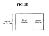
- FIGS. 2C and 2D illustrate the mobile terminal 100 and the display unit 151 according to various embodiments of the present invention.
- the display module 151 can include a first display and a second display which are physically separated from each other.
- the first display or main display
- the second display or sub display
- the sub display is separated from the mobile terminal and detachably combined with the mobile terminal body through an interface to display data from the mobile terminal 100.
- the display module 151 can include first and second displays which are logically separated from each other in a display panel, as illustrated in FIG. 2D .
- FIG. 3 is a conceptual diagram for explaining a proximity depth of the proximity sensor 141.
- the proximity sensor 141 located inside or near the touch screen senses the approach and outputs a proximity signal.
- the proximity sensor 141 can be constructed such that it outputs a proximity signal according to the distance between the pointer approaching the touch screen and the touch screen (referred to as "proximity depth").
- the distance in which the proximity signal is output when the pointer approaches the touch screen is referred to as a detection distance.
- the proximity depth can be known by using a plurality of proximity sensors 141 having different detection distances and comparing proximity signals respectively output from the proximity sensors 141.
- FIG. 3 shows the section of the touch screen in which proximity sensors 141 capable of sensing three different proximity depths are arranged. Proximity sensors 141 capable of sensing less than three or more than four proximity depths can be arranged in the touch screen.
- the pointer when the pointer completely comes into contact with the touch screen (D0), it is recognized as contact touch.
- the pointer When the pointer is located within a distance D1 from the touch screen, it is recognized as proximity touch of a first proximity depth.
- the pointer When the pointer is located in a range between the distance D1 and a distance D2 from the touch screen, it is recognized as proximity touch of a second proximity depth.
- the pointer When the pointer is located in a range between the distance D2 and a distance D3 from the touch screen, it is recognized as proximity touch of a third proximity depth.
- the pointer When the pointer is located at longer than the distance D3 from the touch screen, it is recognized as cancellation of proximity touch.
- the controller 180 can recognize the proximity touch as various input signals according to the proximity distance and proximity position of the pointer with respect to the touch screen and perform various operation controls according to the input signals.
- a CDMA wireless communication system includes mobile terminals 100, base stations 270, base station controllers 275, and a mobile switching center 280.
- the mobile switching center 280 is connected to a public switch telephone network (PSTN) 290.
- PSTN public switch telephone network
- the mobile switching center 280 is connected to the base station controllers 275.
- the base station controllers 275 are connected to the base stations 270 through backhaul lines.
- the backhaul lines may be constructed according to E1/T1, ATM, IP, PPP, frame relay, HDSL, ADSL or xDSL well-known in the art.
- the CDMA wireless communication system may include at least two base station controllers 275.
- Each base station 270 may include a sector or sectors and each sector may include an omnidirectional antenna or an antenna adjusted to a specific radiation direction from the base station 270. Otherwise, each sector may include two diversity reception antennas.
- Each base station 270 is constructed to have frequency assignments, and the frequency assignments may have specific spectra (for example, 1.25MHz and 5MHz). Intersection of sectors and frequency assignments may be referred to a CDMA channel.
- the base stations 270 may be referred to as base station transceiver subsystems (BTSs). "Base station” may be used as a term that collectively designates the base station controller 275 and one or more base stations 270 in several examples. Furthermore, the base stations 270 may be referred to as "cell sites”. Otherwise, individual sectors of a given base station 270 may be referred to as cell sites.
- BTSs base station transceiver subsystems
- a terrestrial DMB transmitter 295 can transmit broadcast signals to the mobile terminals 100 operating in the CDMA wireless communication system.
- the broadcast receiving module 111 of each mobile terminal 100 is constructed to receive the broadcast signals transmitted from the DMB transmitter 295. This can be similarly applied to different types of broadcast and multicast signaling as described above.
- FIG. 4 illustrates global positioning system (GPS) satellites 300. These satellites 300 can track the positions of some or all of the mobile terminals 100. Although two satellites are shown in FIG. 4 , position information can be obtained from less than or more than two satellites. In addition, other position-tracking techniques (for example, position-tracking techniques that can substitute for GPS technique or can be added to the GPS technique) can be used. If required, some or all of the GPS satellites 300 can support satellite DMB transmission separately or additionally.
- GPS global positioning system
- the base stations 270 receive reverse link signals from the mobile terminals 100.
- the mobile terminals 100 may be in a state that the mobile terminals 100 are making calls, sending messages or performing other communications.
- the reverse link signals received by the base stations 270 are processed by the base stations 270.
- the processed data is transmitted to the base station controllers 275 connected to the base stations 270.
- the base station controllers 275 provide call resource allocation and mobility management functionality including soft handoffs between the base stations 270.
- the base station controllers 275 transmit the received data to the mobile switching center 280.
- the mobile switching center 280 provides additional routing services for interfacing with the PSTN 290.
- the PSTN 290 interfaces with the mobile switching center 280
- the mobile switching center 280 interfaces with the base station controllers 275.
- the base station controllers 275 control the base stations 270 to transmit forward link signals to the mobile terminals 100.
- FIG. 5 is a flowchart illustrating a method of controlling the mobile terminal 100 according to an embodiment of the present invention.
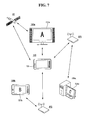
- FIGS. 6 and 7 illustrate connecting the mobile terminal 100 with external electronic devices 100a, 100b and 100c.
- the mobile terminal 100 outputs contents information acquired from the external devices 100a, 100b and 100c and controls the external electronic devices 100a, 100b and 100c based on the contents information.
- the mobile terminal 100 may provide a user interface capable of effectively outputting and controlling the contents information.
- the controller 180 of the mobile terminal 100 may connect the mobile terminal 100 to the external electronic devices 100a, 100b and 100c (S10).
- the external electronic devices are consumer electronic devices such as a TV 100a, a mobile terminal or tablet computing device 100b, and a computer 100c.
- the external electronic devices 100a, 100b and 100c may include various electronic devices except for specific electronic devices. For example, if the user currently operates the mobile terminal 100, electronic devices other than the mobile terminal 100 may be referred to as external electronic devices. If the user currently operates the first external electronic device 100a, the mobile terminal 100 and the second and third external electronic devices 100b and 100c may be referred to as external electronic devices. That is, the term "external" electronic device is a relative term. However, electronic devices other than the mobile terminal 100 are generally referred to as the external electronic devices 100a, 100b and 100c hereinafter for the convenience of understanding. Furthermore, although the number of the external electronic devices 100a, 100b and 100c is three in several drawings and the following description, the number of the external electronic devices is not limited to three and may be less than or greater than three.
- the external electronic devices 100a, 100b and 100c may wire-communicate or wireless-communicate with other electronic devices.
- the wireless communication method of the external electronic devices 100a, 100b and 100c may involve communication with the wireless communication unit 110 of the mobile terminal 100 so that detailed explanation thereof is omitted. Connections between the mobile terminal 100 and the external electronic devices 100a, 100b and 100c will be explained in detail later with reference to FIGS. 6 and 7 .
- the controller 180 may acquire information about contents being output from the external electronic devices 100a, 100b and 100c (S20).
- the external electronic devices 100a, 100b and 100c may respectively output contents through displays 151a, 151b and 151c included therein.
- the information about contents may correspond to the contents themselves or may include description of the contents and information about the source of the contents.
- the mobile terminal 100 can acquire the contents 'A' from the first external electronic device 100a.
- the mobile terminal 100 can acquire detailed information including the title and running time of the contents 'A'.
- the mobile terminal 100 may acquire the address of the source of the contents 'A', such as a universal resource locator (URL). If the mobile terminal 100 acquires the address of the contents source, the mobile terminal 100 can obtain the contents 'A' without directly receiving the contents 'A' through communication with the first external electronic device 100a.
- the controller 180 of the mobile terminal 100 can select one of a route of the acquisition of the contents from the address of the contents source and a route of the acquisition of the contents from the first external electronic device 100a, which is more advantageous in terms of data transmission rate.
- the controller 180 may output widgets reflecting the acquired contents information from the mobile terminal 100 (S30).
- the contents information may include information related to rendering of contents. In such cases, it may be more easily understood if the contents are assumed to be a moving picture (also referred to herein as video). For example, when the mobile terminal 100 transmits contents to at least one of the external electronic devices 100a, 100b, and 100c, information regarding reproduction time point of the contents that is being reproduced at the mobile terminal 100 can be transmitted along with the contents.
- the external electronic device 100a, 100b, and/or 100c which has received the contents can reproduce the contents continuously without repeating the parts that were already reproduced in the mobile terminal 100 or researching of the contents by a user.
- the information regarding reproduction time point allows seamless reproduction of the contents such that a user can watch the contents via the external electronic device 100a, 100b, and/or 100c without additionally controlling the same.
- the contents information can be transmitted from the mobile terminal 100 to the external electronic devices 100a, 100b, and/or 100c in response to a touch and drag input comprising touching a widget and then dragging the same to a desired external electronic device on a display screen of the display module 151.
- a touch and drag input comprising touching a widget and then dragging the same to a desired external electronic device on a display screen of the display module 151.
- the touch and drag input may be touching a first widget and then dragging the first widget to a second widget on the display screen.
- the mobile terminal 100 can transmit the contents of a first external electronic device 100a corresponding to the first widget to a second external electronic device 100b corresponding to the second widget, and at the same time, can also transmit contents information including reproduction time point of the contents being transmitted.
- the second external electronic device 100b that has received the contents and/or contents information can reproduce the contents continuously from the reproduction point indicated in the contents information.
- contents and/or contents information may be transmitted to a plurality of external electronic devices 100a, 100b, and 100c at the same time. For example, if a plurality of widgets are selected by a user via multi-touch, the mobile terminal 100 may transmit the contents and/or contents information to the plurality of external electronic devices 100a, 100b, and 100c at the same time. Transmission of contents and/or contents information in response to selection of widget(s) will be described in more detail later in the corresponding section.
- the acquired contents information may be output in the form of widgets.
- the widgets respectively corresponding to the contents information may represent the contents information in the form of icons and reflect the status of each of the external electronic devices 100a, 100b and 100c.
- images output from the external electronic devices 100a, 100b and 100c can be displayed in synchronization with the widgets or relative locations of the external electronic devices 100a, 100b and 100c may be represented by relative locations of the widgets displayed on the display module 151.
- the mobile terminal 100 can output the acquired contents information in the form of widgets, the user can enjoy contents through various routes. For example, if the first external electronic device 100a corresponds to a TV receiver located in a living room of a house, the user may watch the contents 'A' through the TV receiver 100a in the living room. In this case, when the user needs to go out of the house, the user can transfer the contents 'A' and the information about the contents 'A' being output from the first external electronic device 100a to the mobile terminal 100. Further, the user can play the contents 'A' in the mobile terminal 100 based on the information about the contents 'A' received by the mobile terminal 100. Accordingly, the user can continuously watch the contents 'A' and convenience of use can be improved.
- the user may watch the contents 'A' corresponding to a soccer game through the first external electronic device 100a which is a TV receiver in a living room of the house.
- the contents 'A' output through the TV receiver may be a moving picture obtained by photographing a soccer stadium with a camera.
- the user may operate the mobile terminal 100 to acquire information about the contents 'A' from the first external electronic device 100a.
- the user may output an image, i.e., the soccer game, photographed by the camera through the mobile terminal 100 based on the acquired information. That is, the user can output the identical contents via both one of the external electronic devices and another electronic device such that at least one of the viewpoint and output time of the contents is different from that of the image. By using this function, the user can enjoy a desired best image.
- the controller 180 may receive an operating signal with respect to the widgets (S40) and control the external electronic devices 100a, 100b and 100c based on the received operating signal (S50).
- the operating signal may be a control signal generated by the user or a control operation of the controller 180.
- the operating signal may be a signal generated in response to a touch input applied to the display module 151 of the mobile terminal 100 to change contents to be displayed on the overall screen of the display module 151 or change the images displayed on the external electronic devices 100a, 100b and 100c.
- the controller 180 may output a control signal for changing the operations of the external electronic devices 100a, 100b and 100c based on the operating signal. For example, the controller 180 can generate a control signal for outputting the contents 'A', being output from the first external electronic device 100a, through the second external electronic device 100b.
- the mobile terminal 100 can directly communicate with the external electronic devices 100a, 100b and 100c to acquire contents information.
- the first, second and third external electronic devices 100a, 100b and 100c may be located around or near the mobile terminal 100.
- the first, second and third displays 151 a, 151b and 151c respectively provided to the first, second and third external electronic devices 100a, 100b and 100c may respectively display contents 'A', 'B' and 'C'.
- the mobile terminal 100 may communicate with the first, second and third external electronic devices 100a, 100b and 100c through WiFi Direct which enables direct peer-to-peer (P2P) communication between electronic devices without having an additional access point (AP) for relaying data communication.
- WiFi Direct which enables direct peer-to-peer (P2P) communication between electronic devices without having an additional access point (AP) for relaying data communication.
- Ad-hoc similar to WiFi Direct. While Ad-hoc is used for electronic devices relatively close to each other and has a communication speed limited to 11 Mbps, WiFi Direct can support 802.11 n to permit electronic devices located farther apart from each other to directly communicate with each other at a communication speed of approximately 300Mbps.
- Sharing contents information between the mobile terminal 100 and the first, second and third external electronic devices 100a, 100b and 100c via direct/indirect communication to display the contents information may be referred to as 3-screen or n-screen.
- the mobile terminal 100 and the first, second and third external electronic devices 100a, 100b and 100c may synchronize their video signals and/or audio signals with each other and output the synchronized signals.
- the mobile terminal 100 may directly or indirectly communicate with the first, second and third external electronic devices 100a, 100b and 100c.
- the mobile terminal 100 can communicate with the third external electronic device 100c via a first AP AP1 and communicate with the second external electronic device 100b via a second AP AP2. That is, the mobile terminal 100 can indirectly exchange contents information with the second and third external electronic devices 100b and 100c via external networks.
- the mobile terminal 100 can directly communicate with the first external electronic device 100a using WiFi Direct.
- Contents shared by the mobile terminal 100 and the first external electronic device 100a may be received through a satellite ST. That is, contents information can be stored in an external storage that is not in the mobile terminal 100 or the first external electronic device 100a. Even when the contents information is stored in the external storage and transmitted from the external storage to the mobile terminal 100 and the first external electronic device 100a through the satellite ST, the mobile terminal 100 can transmit a control signal to the first external electronic device 100a.
- the control signal transmitted to the first external electronic device 100a may affect the contents 'A' output from the first external electronic device 100a. For example, the control signal can stop outputting the contents 'A' or change the time and/or viewpoint of the contents 'A'.
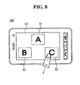
- FIGS. 8 and 9 illustrate an operation of a mobile terminal 100 according to an embodiment of the present invention to acquire contents information from the external electronic devices and output the contents information.
- the controller 180 of the mobile terminal 100 may display first, second and third widgets S1, S2 and S3 acquired from the external electronic devices 100a, 100b and 100c on the display module 151.
- the user may select a desired one of the first, second and third widgets S1, S2 and S3 and display the selected widget on the overall screen of the display module 151.
- the controller 180 may execute a managing mode of displaying acquired images in the form of thumbnails.
- the first, second and third widgets S1, S2 and S3 displayed in the form of thumbnails may represent positions of the external electronic devices 100a, 100b and 100c relative to the position of the mobile terminal 100.
- the first widget S1 is acquired from the first external electronic device 100a located in front of the mobile terminal 100
- the second widget S2 is acquired from the second external electronic device 100b located on the left of the mobile terminal 100
- the third widget S3 is acquired from the third external electronic device 100c located on the right of the mobile terminal 100.
- the controller 180 may display the first, second and third widgets S1, S2 and S3 based on these relative positions.
- the user may select a desired one of the displayed first, second and third widgets S1, S2 and S3 by touching the desired one with a finger F as shown in FIG. 8 .
- the widget S3 selected by the user may be displayed on the overall screen area of the display module 151. Accordingly, the user can seamlessly view the third widget S3, which has been displayed on the third external electronic device 100c, through the mobile terminal 100.
- the display module 151 displaying the third widget S3 may also display a first icon I1. When the first icon I1 is selected, the controller 180 may start the managing mode.
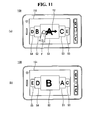
- FIGS. 10 , 11 and 12 illustrate operations of displaying contents information acquired by the mobile terminal 100 according to an embodiment of the present invention and manipulating the displayed contents information.
- the mobile terminal 100 can change displayed images through various operations.
- the display module 151 of the mobile terminal 100 may display the first, second and third widgets S1, S2 and S3 respectively acquired from the first, second and third external electronic devices 100a, 100b and 100c.
- the user may select one of the first, second and third widgets S1, S2 and S3, which will be displayed.
- the user can locate a desired widget at the center of the display module 151.
- the first widget S1 can be displayed in the overall screen area of the display module 151 in the case of FIG. 10(a) .
- the user may touch the display module 151 through a first touch operation T1.
- the first, second and third widgets S1, S2 and S3 can rotate in the dragging direction.
- the layout of images displayed on the display module 151 may be changed.
- the layout is changed such that the second widget S2 is displayed in front, as shown in FIG. 10(c)
- the second widget S2 can be displayed in the overall screen area of the display module 151.
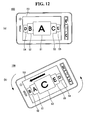
- the display module 151 of the mobile terminal 100 may display first through fifth widgets S1 through S5 acquired from various electronic devices.
- the first widget S1 among the displayed widgets S1 through S5 may be displayed in the overall screen area of the display module 151.
- the user may want to display another image.
- the user may touch the display screen of the display module 151 with his/her finger F through a second touch operation T2 in the horizontal direction.
- the controller 180 may rotate the first through fifth widgets S1 through S5 on a virtual axis.
- the widgets S1 through S5 displayed on the display module 151 sequentially rotate and a specific widget, the second widget S2, is displayed at the center of the display module 151.
- the second widget S2 displayed at the center of the display module 151 may be displayed in the overall screen area of the display module 151 in response to a control signal of the controller 180.
- the display module 151 of the mobile terminal 100 may display the first through fifth widgets S1 through S5 acquired from the various electronic devices.
- the sensing unit 140 of the mobile terminal 100 which may include an acceleration sensor, can sense the posture of the mobile terminal 100. Accordingly, the controller 180 can move the displayed first through fifth widgets S1 through S5 to the left or right according to the direction sensed by the acceleration sensor. The user can control the moving speed of the first through fifth widgets S1 through S5 by adjusting the tilt of the mobile terminal 100.
- FIG. 13 is a flowchart illustrating, in detail, the operation S40 of receiving an operating signal with respect to output contents information described in FIG. 5 .
- the operation S40 of receiving an operating signal with respect to contents information output from the mobile terminal 100 may include selecting the managing mode (S41).
- the managing mode displays searched external electronic devices such that the user can operate the displayed external electronic devices.
- the searched external electronic devices may be displayed in the form of thumbnails. Further, the display form of the searched external electronic devices can be changed, new external electronic devices can be searched, or searched external electronic devices can be deleted in the managing mode, which will be explained in more detail later.
- the external electronic devices can be displayed based on the relative positions thereof.
- the relative positions may be positions of the first, second and third external electronic devices 100a, 100b and 100c relative to the position of the mobile terminal 100.
- the positions of the first, second and third external electronic devices 100a, 100b and 100c are relative to the mobile terminal 100 that is positioned at the center on the display module 151.
- An operating signal with respect to the displayed screen may be received (S43) and the displayed screen may be changed in response to the received operating signal (S44).
- the operating signal with respect to the displayed screen may be a signal generated by a user's touch on images displayed on the display module 151.
- the controller 180 may change the display form of the display module 151 in response to the operating signal. For example, the controller 180 can change the layout of displayed images or change images shared by the mobile terminal 100 and the external electronic devices 100a, 100b and 100c.
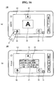
- FIGS. 14 through 19 illustrate operations of outputting contents information received from external electronic devices and controlling the external electronic devices based on the contents information.
- the user can operate received contents information in various manners to control data communication with the external electronic devices 100a, 100b and 100c.
- the display module 151 of the mobile terminal 100 may display the first widget S1 received from the first external electronic device 100a.
- the user may select a second icon I2 displayed at a certain portion of the display module 151.
- the second icon I2 may be a menu for entering the managing mode.
- the first, second and third widgets S1, S2 and S3 respectively received from the first, second and third external electronic devices 100a, 100b and 100c may be displayed on the display module 151. Furthermore, a selected screen CS may be displayed at the center of the display module 151.
- the selected screen CS may be an image to be displayed in the overall screen area of the display module 151 when the managing mode is ended. That is, an image selected from images of the external electronic devices to be shared by the user may be displayed.
- the selected screen CS may display images received from the external electronic devices 100a, 100b and 100c continuously or display images received from the external electronic devices 100a, 100b and 100c at specific intervals. That is, the selected screen CS may display a video or a still image.
- the first widget S1 received from the first external electronic device 100a is displayed as the selected screen CS.
- the user may change the display of the selected screen CS.
- the display of the selected screen CS may be changed through a third touch operation T3 starting from one of the first, second and third widgets S1, S2 and S3, for example S2, toward the selected screen CS.
- the second widget S2 instead of the first widget S1 is selected as the selected screen CS according to the third touch operation T3.
- the user may select the first icon I1 for displaying the selected screen CS in the overall screen area of the display module 151.
- the second widget S2 selected as the selected screen CS may be displayed on the display module 151. Further, the second icon I2 for entering the managing mode may be displayed on a portion of the display module 151.
- the user may select the second widget S2 among displayed images with his/her finger F.
- detailed information about contents information corresponding to the second widget S2 selected by the user may be displayed in a first pop-up window P1.
- the contents information may be the contents, description of the contents and information about the source of the contents.
- the first pop-up window P1 may display the description of the contents.
- the information about the contents source may be displayed if required.
- specific contents information may be blocked from being shared.
- the second external electronic device 100b corresponding to the second widget S2 does not allow the contents information corresponding to the second widget S2 to be shared with the mobile terminal 100.
- the controller 180 may inform the user of the fact through a specific icon S2.
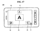
- the display module 151 may display a rotation icon I3.
- the rotation icon I3 may be an object rotating clockwise or counter clockwise in response to a fourth touch operation T4.
- the rotation icon I3 may have a direction indicator D to indicate the direction currently pointing by the rotation icon 13.
- the rotation icon 13 points toward the first widget S1 as indicated by the direction of the direction indicator D. Accordingly, the first widget S1 can be displayed on the overall screen of the display 151 when the user selects the first icon I1.
- the user may rotate the rotation icon I3 to change the image to be displayed on the overall screen of the display module 151.
- the direction indicator D points toward the second widget S2.
- the rotation icon I3 may be fixed.
- the first, second and third widgets S1, S2 and S3 arranged around the rotation icon I3 may be rotated clockwise or counterclockwise in the direction of a fifth touch operation T5.
- the user may rotate the first, second and third widgets S1, S2 and S3 in the direction of the fifth touch operation T5 to display the second widget S2 instead of the first widget S1 on the overall screen of the display module 151.
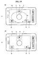
- FIG. 20 illustrates an operation of a mobile terminal 100 according to an embodiment of the present invention to search for a new external device.
- the mobile terminal 100 can provide a user interface by which the user can manually search for an external electronic device.
- the user may rotate the rotation icon I3 such that the direction indicator D points toward a direction in which no image is currently displayed.
- the controller 180 may search for a new external electronic device which is present in the pointed direction.
- the mobile terminal 100 can communicate with the new external electronic device to receive contents information from the new external electronic device.
- the controller 180 may display a fourth image S4 corresponding to the newly received external electronic device on the corresponding position of the display module 151.
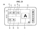
- FIG. 21 illustrates a layout of external electronic devices searched by a mobile terminal according to an embodiment of the present invention.
- the mobile terminal 100 can display images received from the searched external electronic devices in respective spaces.
- the mobile terminal 100 may receive contents information corresponding to the first through fifth widgets S1 through S5.
- the external electronic devices corresponding to the first and second widgets S1 and S2 the external electronic device corresponding to the third widget S3 and the external electronic devices corresponding to the fourth and fifth widgets S4 and S5 may be respectively located in different spaces or areas.
- the external electronic devices corresponding to the first and second widgets S1 and S2 may be located in a large room on the second floor
- the external electronic device corresponding to the third widget S3 may be located in a small room on the second floor
- the external electronic devices corresponding to the fourth and fifth widgets S4 and S5 may be placed in a living room on the first floor.
- the controller 180 may divide display screen of the display module 151 into first, second and third areas A1, A2 and A3 to visually represent the external electronic devices arranged in different spaces.
- the selected screen CS displaying contents selected to be shared with the mobile terminal 100 may be displayed on a designated portion of the display module 151.
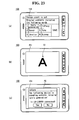
- FIG. 22 is a flowchart illustrating an operation relating to a screen event in a mobile terminal according to an embodiment of the present invention and FIG. 23 illustrates the operation relating to the screen event shown in FIG. 22 .
- the mobile terminal 100 may inform the user when a set screen event is received.
- the screen event may be a function of displaying information in which the user is interested in. Specifically, when contents, which satisfy a condition set by the user among the contents output from external electronic devices, are output, the screen event displays the contents of interest on the mobile terminal 100.
- the controller 180 determines whether a set screen event signal is received (S61), displays the generation of the screen event (S62) and determines whether mobile terminal 100 is connected to an external electronic device generating the screen event (S63).
- the set screen event signal may be generated only when a specific condition previously set by the user is satisfied. For example, if the user is interested in tropical fish, the user can set 'cardinal tetra' as a keyword.
- the controller 180 filters contents information received from external electronic devices connected to the mobile terminal 100 to determine whether contents information including the keyword is present. If there is contents information including the keyword, the controller 180 informs the user by displaying the information, indicating that there is contents information including the keyword, on the display module 151 of the mobile terminal 100.
- the user of the mobile terminal 100 sets a screen event by inputting specific keywords in which the user is interested in and saving the keywords. Thereafter, while the display module 151 of the mobile terminal 100 displays the first widget S1, as shown in FIG. 23(b) , if the set screen event is generated, a second pop-up window P2 may be displayed, as shown in FIG. 23(c) .
- the second pop-up window P2 may display the detailed information about the screen event and the name of the external electronic device generating the screen event.
- the second pop-up window P2 may additionally display a message that inquires whether to connect to the external electronic device.
- FIGS. 24 and 25 are flowcharts illustrating an operation of a mobile terminal according to an embodiment of the present invention to share a contents output resource.
- the mobile terminal 100 can share the contents output resource.
- the contents output resource may be an application, codec or the like which can output specific contents. Even when contents are shared by electronic devices, the shared contents cannot be output properly if there is no resource capable of outputting the shared contents. Furthermore, although the contents may be output properly from a specific electronic device, the same contents may not be output properly from another electronic device because the resolution of the contents may be different from that of the other electronic device. The mobile terminal 100 can prevent these problems by sharing the contents output resource.
- operation S30 in FIG. 5 may include checking the contents output resource (S31).
- the operation S31 of checking the contents output resource may be performed on the mobile terminal 100 connected to other external electronic devices. Specifically, the operation S31 may be performed when the mobile terminal 100 receives contents information from the external electronic devices.
- the controller 180 may determine whether the contents information can be output properly (S32) and acquire the contents output resource from an external electronic device connected to the mobile terminal 100 if the contents information cannot be output properly (S33) or obtain the contents output resource from another external electronic device (S34).
- an external electronic device that transmits contents to the mobile terminal 100 may possess the contents output resource capable of playing the contents. Accordingly, if the mobile terminal 100 does not have contents output resource, the mobile terminal 100 may receive the contents output resource from the external electronic device. If the external electronic device does not have the contents output resource, the mobile terminal 100 may acquire the contents output resource from other external electronic devices.
- the other external electronic device may be one of electronic devices that are currently connected to the mobile terminal 100 and a server linked to a network. Finally, when the contents output resource is secured, the acquired contents may be output (S35).
- the contents output resource may be transmitted from the mobile terminal 100 to an external electronic device.
- operation S50 in FIG. 5 i.e., controlling the external electronic devices based on the received operating signal, may include generating a signal for operating transmission of contents to an external electronic device (S51).
- the signal for operating transmission of contents to the external electronic device may be an input signal generated in response to user input or a control signal of the controller 180 for transmitting specific contents from the mobile terminal 100 to the external electronic device.
- the controller 180 may check whether the external electronic device has the contents output resource (S52). That is, the mobile terminal 100 which will transmit the contents can check whether the external electronic device has the contents output resource capable of outputting the contents.
- the controller 180 may transmit the contents output resource (S54), and then transmit the contents (S55).
- the external electronic device which received the contents may receive user input with regard to processing of the contents received along with an alert of occurrence of a screen event.
- the external electronic device may display a pop up window to receive an input for selecting an operation such as displaying, storing, reproducing, deleting, or rejecting the contents.
- the user may select a desired operation. Once the user input is received, an operation corresponding to the user input is performed. Furthermore, the external device which received the contents may generate and display an icon or widget corresponding to the received contents so that operations related to the contents can be performed easily in the future.
- the mobile terminal 100 which will transmit the contents may have the contents output resource for outputting the contents. Accordingly, the mobile terminal 100 may also transmit the contents output resource to the external electronic device. When the transmission of the contents output resource to the external electronic device is finished and the external electronic device is ready to output the contents, the contents can be transmitted to the external electronic device.
- the external electronic devices have been described as being fixed to specific positions around the mobile terminal in the aforementioned embodiments, the positions of the external electronic devices can be changed according to the variable position of the mobile terminal.
- electronic devices capable of communicating with the mobile terminal moving with the user when the user goes to work from home by transportation means may correspond to the external electronic devices.
- the above-described method of controlling the mobile terminal may be written as computer programs and may be implemented in digital microprocessors that execute the programs using a computer readable recording medium.
- the method of controlling the mobile terminal may be executed through software.
- the software may include code segments that perform required tasks. Programs or code segments may also be stored in a processor readable medium or may be transmitted according to a computer data signal combined with a carrier through a transmission medium or communication network.
- the computer readable recording medium may be any data storage device that can store data that can be thereafter read by a computer system. Examples of the computer readable recording medium may include read-only memory (ROM), random-access memory (RAM), CD-ROMs, DVD ⁇ ROM, DVD-RAM, magnetic tapes, floppy disks, optical data storage devices.
- ROM read-only memory
- RAM random-access memory
- CD-ROMs CD-ROMs
- DVD ⁇ ROM DVD-RAM
- magnetic tapes floppy disks
- optical data storage devices optical data storage devices.
- the computer readable recording medium may also be distributed over network coupled computer systems so that the computer readable code is stored and executed in a distribution fashion.
- a mobile terminal may include a first touch screen configured to display a first object, a second touch screen configured to display a second object, and a controller configured to receive a first touch input applied to the first object and to link the first object to a function corresponding to the second object when receiving a second touch input applied to the second object while the first touch input is maintained.
- a method may be provided of controlling a mobile terminal that includes displaying a first object on the first touch screen, displaying a second object on the second touch screen, receiving a first touch input applied to the first object, and linking the first object to a function corresponding to the second object when a second touch input applied to the second object is received while the first touch input is maintained.
- any reference in this specification to "one embodiment,” “an embodiment,” “example embodiment,” etc. means that a particular feature, structure, or characteristic described in connection with the embodiment is included in at least one embodiment of this document.
- the appearances of such phrases in various places in the specification are not necessarily all referring to the same embodiment.
Landscapes
- Engineering & Computer Science (AREA)
- Software Systems (AREA)
- Theoretical Computer Science (AREA)
- Physics & Mathematics (AREA)
- General Engineering & Computer Science (AREA)
- General Physics & Mathematics (AREA)
- Human Computer Interaction (AREA)
- Databases & Information Systems (AREA)
- Technology Law (AREA)
- Computer Hardware Design (AREA)
- Computer Security & Cryptography (AREA)
- Computer Networks & Wireless Communication (AREA)
- Signal Processing (AREA)
- Multimedia (AREA)
- Data Mining & Analysis (AREA)
- Telephone Function (AREA)
- User Interface Of Digital Computer (AREA)
Applications Claiming Priority (1)
| Application Number | Priority Date | Filing Date | Title |
|---|---|---|---|
| KR1020100042565A KR101680344B1 (ko) | 2010-05-06 | 2010-05-06 | 이동 단말기 및 그 제어방법 |
Publications (2)
| Publication Number | Publication Date |
|---|---|
| EP2385462A1 EP2385462A1 (en) | 2011-11-09 |
| EP2385462B1 true EP2385462B1 (en) | 2015-07-08 |
Family
ID=44244700
Family Applications (1)
| Application Number | Title | Priority Date | Filing Date |
|---|---|---|---|
| EP11003022.8A Not-in-force EP2385462B1 (en) | 2010-05-06 | 2011-04-11 | Mobile terminal and method of controlling the same |
Country Status (5)
| Country | Link |
|---|---|
| US (1) | US8990721B2 (zh) |
| EP (1) | EP2385462B1 (zh) |
| KR (1) | KR101680344B1 (zh) |
| CN (1) | CN102238281A (zh) |
| ES (1) | ES2546232T3 (zh) |
Families Citing this family (59)
| Publication number | Priority date | Publication date | Assignee | Title |
|---|---|---|---|---|
| US8965271B1 (en) * | 2010-05-07 | 2015-02-24 | Enconcert, Inc. | Method and mechanism for coordinated capture and organization of multimedia data |
| KR101742578B1 (ko) * | 2011-01-14 | 2017-06-01 | 삼성전자주식회사 | 컨텐츠 관리 방법 및 이를 적용한 디스플레이 장치 |
| US9762662B2 (en) | 2011-05-12 | 2017-09-12 | Microsoft Technology Licensing, Llc | Mass re-formation of groups in a peer-to-peer network |
| TWI442664B (zh) * | 2011-08-19 | 2014-06-21 | Primax Electronics Ltd | 無線電腦周邊裝置之無線充電方法 |
| TWI470535B (zh) * | 2011-11-29 | 2015-01-21 | 多維度頁面管理方法與使用此方法的電子裝置 | |
| KR101256838B1 (ko) * | 2011-12-14 | 2013-04-30 | 주식회사 유비온 | 주 스크린과 제2 스크린의 연결을 위한 상호 이용 가능한 정보를 전달하는 방법, 장치 및 시스템 |
| US8812987B2 (en) * | 2011-12-20 | 2014-08-19 | Wikipad, Inc. | Virtual multiple sided virtual rotatable user interface icon queue |
| CN104137064B (zh) * | 2011-12-28 | 2018-04-20 | 诺基亚技术有限公司 | 应用切换器 |
| CN104137048B (zh) | 2011-12-28 | 2019-10-25 | 诺基亚技术有限公司 | 提供应用的打开实例 |
| CN104137527A (zh) * | 2011-12-28 | 2014-11-05 | 诺基亚公司 | 相机控制应用 |
| US8996729B2 (en) | 2012-04-12 | 2015-03-31 | Nokia Corporation | Method and apparatus for synchronizing tasks performed by multiple devices |
| EP2798833A4 (en) * | 2011-12-28 | 2015-06-03 | Nokia Corp | CAMERA CONTROL APPLICATION |
| US9164779B2 (en) | 2012-02-10 | 2015-10-20 | Nokia Technologies Oy | Apparatus and method for providing for remote user interaction |
| KR101922023B1 (ko) * | 2012-02-20 | 2018-11-26 | 삼성전자주식회사 | 디스플레이장치 및 그 제어방법 |
| CN102638774A (zh) * | 2012-03-31 | 2012-08-15 | 王方淇 | 一种移动终端数据同步分享的方法和系统 |
| USD731526S1 (en) * | 2012-04-17 | 2015-06-09 | Hon Hai Precision Industry Co., Ltd. | Display screen with graphical user interface of an electronic program guide |
| CN102710612B (zh) * | 2012-05-11 | 2016-06-29 | 张伟 | 实现多方交互通信应用的方法及装置 |
| US9176703B2 (en) | 2012-06-29 | 2015-11-03 | Lg Electronics Inc. | Mobile terminal and method of controlling the same for screen capture |
| USD741895S1 (en) * | 2012-12-18 | 2015-10-27 | 2236008 Ontario Inc. | Display screen or portion thereof with graphical user interface |
| JP2014126949A (ja) * | 2012-12-25 | 2014-07-07 | Kyocera Corp | 携帯端末装置、画面制御方法およびプログラム |
| US9511988B2 (en) * | 2012-12-27 | 2016-12-06 | Lancer Corporation | Touch screen for a beverage dispensing system |
| JP2014161673A (ja) | 2013-02-27 | 2014-09-08 | Nintendo Co Ltd | 情報端末制御システム、情報端末制御システムの制御方法、情報処理装置および情報処理装置の制御プログラム |
| US20140258880A1 (en) * | 2013-03-07 | 2014-09-11 | Nokia Corporation | Method and apparatus for gesture-based interaction with devices and transferring of contents |
| KR102083595B1 (ko) * | 2013-03-15 | 2020-03-02 | 엘지전자 주식회사 | 이동 단말기 및 그것의 제어 방법 |
| JP6131090B2 (ja) | 2013-04-16 | 2017-05-17 | 任天堂株式会社 | 情報処理装置、情報を表示する方法、プログラム、および情報処理システム |
| JP2014209279A (ja) * | 2013-04-16 | 2014-11-06 | 任天堂株式会社 | 情報処理装置、情報処理システム、情報処理装置の制御方法、およびその制御プログラム |
| CN103248685A (zh) * | 2013-04-28 | 2013-08-14 | 福建星网锐捷通讯股份有限公司 | 一种基于智能手机之间p2p监控方法及系统 |
| AU352881S (en) * | 2013-06-05 | 2013-12-11 | Samsung Electronics Co Ltd | Display screen with graphical user interface |
| USD757064S1 (en) * | 2013-06-05 | 2016-05-24 | Samsung Electronics Co., Ltd. | Display screen or portion thereof with graphical user interface |
| AU352882S (en) * | 2013-06-05 | 2013-12-11 | Samsung Electronics Co Ltd | Display screen with graphical user interface |
| WO2014201876A1 (zh) * | 2013-06-17 | 2014-12-24 | 华为技术有限公司 | 屏幕分享方法和相关设备及通信系统 |
| KR102018378B1 (ko) * | 2013-07-08 | 2019-09-04 | 엘지전자 주식회사 | 전자 기기 및 전자 기기의 제어 방법 |
| GB201313167D0 (en) | 2013-07-24 | 2013-09-04 | Ibm | Automatic rotation of display contents of a handheld companion device rigidly attached to a handheld mobile device |
| KR101847074B1 (ko) * | 2013-08-26 | 2018-04-09 | 삼성전자주식회사 | 영상 표시 방법 및 장치 |
| CN104469249B (zh) * | 2013-09-16 | 2017-11-03 | 联想(北京)有限公司 | 一种信息处理方法及第一电子设备 |
| JP2017504982A (ja) * | 2013-10-29 | 2017-02-09 | コーテック インダストリーズ プロプライアタリー リミテッド | 適合型マルチモードワイヤレス電源、ライト、および自動化 |
| KR101917700B1 (ko) * | 2013-12-23 | 2018-11-13 | 엘지전자 주식회사 | 이동 단말기 및 그 제어 방법 |
| KR101588294B1 (ko) | 2013-12-30 | 2016-01-28 | 삼성전자주식회사 | 사용자 인터렉션을 제공하는 사용자 단말 장치 및 그 방법 |
| CN105556866B (zh) * | 2014-02-21 | 2018-05-15 | 联发科技股份有限公司 | 无线通信连接的建立方法及其电子装置 |
| CN104010385B (zh) * | 2014-06-09 | 2018-05-15 | 宇龙计算机通信科技(深圳)有限公司 | 数据传输方法和数据传输系统 |
| KR102269481B1 (ko) * | 2014-10-17 | 2021-06-28 | 삼성전자주식회사 | 디바이스 간에 화면 공유 방법 및 이를 이용하는 디바이스 |
| CN104349199B (zh) * | 2014-11-21 | 2017-09-26 | 王方淇 | 一种信息同步方法及装置 |
| CN105828151B (zh) * | 2015-01-07 | 2019-09-13 | 中国移动通信集团公司 | 一种显示处理方法及装置 |
| CN104702882B (zh) * | 2015-03-17 | 2019-08-16 | 努比亚技术有限公司 | 基于volte的视频通话装置和方法 |
| KR102306536B1 (ko) * | 2015-04-01 | 2021-09-29 | 삼성전자주식회사 | 위젯 제공 시스템 및 방법 |
| CN105630276B (zh) * | 2015-04-28 | 2019-12-10 | 宇龙计算机通信科技(深圳)有限公司 | 富媒体通信中共享内容的显示方法及显示装置 |
| CN106610765B (zh) * | 2015-10-26 | 2020-05-19 | 网易(杭州)网络有限公司 | 按钮间位置相对固定的切换方法及装置、移动客户端和电脑客户端 |
| ES2610504A1 (es) * | 2015-10-27 | 2017-04-27 | Universidad Politécnica de Madrid | Tarjeta electrónica de membresía |
| CN105867805B (zh) * | 2016-03-24 | 2020-01-17 | 广州华多网络科技有限公司 | 一种信息加载的方法及电子设备 |
| CN105827710B (zh) * | 2016-03-31 | 2019-05-31 | 百度在线网络技术(北京)有限公司 | 车载终端与移动终端协同输入的控制方法及移动终端 |
| CN106059788B (zh) * | 2016-05-06 | 2019-09-17 | 海信集团有限公司 | 智能家居设备的识别方法及装置 |
| USD881278S1 (en) * | 2018-06-13 | 2020-04-14 | Si On Kim | Label |
| US11416205B2 (en) * | 2019-04-16 | 2022-08-16 | Apple Inc. | Systems and methods for initiating and interacting with a companion-display mode for an electronic device with a touch-sensitive display |
| US11625155B2 (en) * | 2020-03-23 | 2023-04-11 | Ricoh Company, Ltd. | Information processing system, user terminal, method of processing information |
| KR20230011795A (ko) * | 2021-07-14 | 2023-01-25 | 삼성전자주식회사 | 위젯을 표시하는 전자 장치 및 이의 제어 방법 |
| US11503358B1 (en) | 2021-10-19 | 2022-11-15 | Motorola Mobility Llc | Electronic devices and corresponding methods utilizing ultra-wideband communication signals for user interface enhancement |
| US11606456B1 (en) | 2021-10-19 | 2023-03-14 | Motorola Mobility Llc | Electronic devices and corresponding methods utilizing ultra-wideband communication signals for user interface enhancement |
| US11907495B2 (en) * | 2021-10-19 | 2024-02-20 | Motorola Mobility Llc | Electronic devices and corresponding methods utilizing ultra-wideband communication signals for user interface enhancement |
| CN117425873A (zh) * | 2022-04-24 | 2024-01-19 | 广州视臻信息科技有限公司 | 内容共享方法、装置、交互平板及存储介质 |
Family Cites Families (14)
| Publication number | Priority date | Publication date | Assignee | Title |
|---|---|---|---|---|
| EP0475581A3 (en) * | 1990-08-30 | 1993-06-23 | Hewlett-Packard Company | Method and apparatus for window sharing between computer displays |
| US5689641A (en) | 1993-10-01 | 1997-11-18 | Vicor, Inc. | Multimedia collaboration system arrangement for routing compressed AV signal through a participant site without decompressing the AV signal |
| CA2295757C (en) * | 1997-06-25 | 2003-08-19 | Samsung Electronics Co., Ltd. | Improved home network, browser based, command and control |
| US6356933B2 (en) | 1999-09-07 | 2002-03-12 | Citrix Systems, Inc. | Methods and apparatus for efficiently transmitting interactive application data between a client and a server using markup language |
| KR20020007310A (ko) | 1999-12-22 | 2002-01-26 | 요트.게.아. 롤페즈 | 가전 제품으로부터 멀티미디어 콘텐트의 원격 전달 |
| TW494691B (en) * | 2000-11-21 | 2002-07-11 | Koninkl Philips Electronics Nv | Mobile device, auxiliary rendering device and arrangement |
| JP4701027B2 (ja) * | 2004-09-02 | 2011-06-15 | キヤノン株式会社 | 情報処理装置、制御方法及びプログラム |
| CN1925527A (zh) * | 2005-08-29 | 2007-03-07 | 吕安姿 | 一种利用移动电话控制家用电器的方法及其系统 |
| KR101526965B1 (ko) * | 2008-02-29 | 2015-06-11 | 엘지전자 주식회사 | 단말기 및 그 제어 방법 |
| CN101662667A (zh) | 2008-08-29 | 2010-03-03 | 北京创先泰克科技有限公司 | 用电话机终端控制摄像装置的控制系统和方法 |
| US8082576B2 (en) * | 2008-09-12 | 2011-12-20 | At&T Mobility Ii Llc | Network-agnostic content management |
| US9342231B2 (en) * | 2008-12-29 | 2016-05-17 | Apple Inc. | Remote control of a presentation |
| CN101534411B (zh) * | 2009-04-08 | 2012-12-12 | 华为终端有限公司 | 一种基于图像的视讯会议控制方法、终端及系统 |
| CN102541414A (zh) * | 2010-12-28 | 2012-07-04 | 英华达(上海)科技有限公司 | 一种能自动切换操作模式的移动终端装置 |
-
2010
- 2010-05-06 KR KR1020100042565A patent/KR101680344B1/ko active IP Right Grant
-
2011
- 2011-04-11 EP EP11003022.8A patent/EP2385462B1/en not_active Not-in-force
- 2011-04-11 ES ES11003022.8T patent/ES2546232T3/es active Active
- 2011-04-18 US US13/089,190 patent/US8990721B2/en not_active Expired - Fee Related
- 2011-05-05 CN CN2011101192772A patent/CN102238281A/zh active Pending
Also Published As
| Publication number | Publication date |
|---|---|
| CN102238281A (zh) | 2011-11-09 |
| US20110276911A1 (en) | 2011-11-10 |
| KR101680344B1 (ko) | 2016-11-28 |
| US8990721B2 (en) | 2015-03-24 |
| EP2385462A1 (en) | 2011-11-09 |
| KR20110123099A (ko) | 2011-11-14 |
| ES2546232T3 (es) | 2015-09-21 |
Similar Documents
| Publication | Publication Date | Title |
|---|---|---|
| EP2385462B1 (en) | Mobile terminal and method of controlling the same | |
| US9313315B2 (en) | Mobile terminal and method of controlling the same for tagging different NFC tags | |
| KR102080746B1 (ko) | 이동 단말기 및 그것의 제어 방법 | |
| KR101690232B1 (ko) | 전자 기기 및 전자 기기의 제어 방법 | |
| KR102127925B1 (ko) | 이동 단말기 및 그것의 제어 방법 | |
| EP2410715B1 (en) | Mobile terminal and controlling method thereof | |
| US9215308B2 (en) | Mobile terminal and control method thereof | |
| US10042596B2 (en) | Electronic device and method for controlling the same | |
| US8666454B2 (en) | Mobile terminal and method of controlling the same | |
| EP2385687B1 (en) | Mobile terminal and control method thereof | |
| KR102130796B1 (ko) | 이동 단말기 및 이의 제어방법 | |
| US20140063181A1 (en) | Mobile terminal and method of controlling the same | |
| EP2706739B1 (en) | Mobile terminal and control method thereof | |
| KR102156140B1 (ko) | 이동 단말기 및 이의 제어방법 | |
| KR101781072B1 (ko) | 전자 기기 및 그 제어 방법 | |
| KR20120014751A (ko) | 이동 단말기 및 그 제어방법 | |
| EP2560353B1 (en) | Mobile terminal and method of controlling the same | |
| KR20130005019A (ko) | 이동 단말기 및 그 제어방법 | |
| KR101643260B1 (ko) | 전자 기기 및 그의 제어 방법 | |
| KR102110205B1 (ko) | 이동 단말기 및 그것의 제어방법 | |
| KR102043151B1 (ko) | 이동 단말기 및 이의 제어방법 | |
| KR20110119297A (ko) | 이동 단말기 및 이것의 이미지 디스플레이 방법 | |
| EP2398260A1 (en) | Mobile terminal and method of controlling the same | |
| KR20100105191A (ko) | 이동 단말기 및 그 정보표시방법 | |
| KR20110115664A (ko) | 이동 단말기 및 그 제어 방법 |
Legal Events
| Date | Code | Title | Description |
|---|---|---|---|
| 17P | Request for examination filed |
Effective date: 20110411 |
|
| AK | Designated contracting states |
Kind code of ref document: A1 Designated state(s): AL AT BE BG CH CY CZ DE DK EE ES FI FR GB GR HR HU IE IS IT LI LT LU LV MC MK MT NL NO PL PT RO RS SE SI SK SM TR |
|
| AX | Request for extension of the european patent |
Extension state: BA ME |
|
| PUAI | Public reference made under article 153(3) epc to a published international application that has entered the european phase |
Free format text: ORIGINAL CODE: 0009012 |
|
| 17Q | First examination report despatched |
Effective date: 20130911 |
|
| GRAP | Despatch of communication of intention to grant a patent |
Free format text: ORIGINAL CODE: EPIDOSNIGR1 |
|
| INTG | Intention to grant announced |
Effective date: 20150202 |
|
| GRAS | Grant fee paid |
Free format text: ORIGINAL CODE: EPIDOSNIGR3 |
|
| GRAA | (expected) grant |
Free format text: ORIGINAL CODE: 0009210 |
|
| AK | Designated contracting states |
Kind code of ref document: B1 Designated state(s): AL AT BE BG CH CY CZ DE DK EE ES FI FR GB GR HR HU IE IS IT LI LT LU LV MC MK MT NL NO PL PT RO RS SE SI SK SM TR |
|
| REG | Reference to a national code |
Ref country code: GB Ref legal event code: FG4D |
|
| REG | Reference to a national code |
Ref country code: AT Ref legal event code: REF Ref document number: 735877 Country of ref document: AT Kind code of ref document: T Effective date: 20150715 Ref country code: CH Ref legal event code: EP |
|
| REG | Reference to a national code |
Ref country code: IE Ref legal event code: FG4D |
|
| REG | Reference to a national code |
Ref country code: DE Ref legal event code: R096 Ref document number: 602011017597 Country of ref document: DE |
|
| REG | Reference to a national code |
Ref country code: ES Ref legal event code: FG2A Ref document number: 2546232 Country of ref document: ES Kind code of ref document: T3 Effective date: 20150921 |
|
| REG | Reference to a national code |
Ref country code: AT Ref legal event code: MK05 Ref document number: 735877 Country of ref document: AT Kind code of ref document: T Effective date: 20150708 |
|
| REG | Reference to a national code |
Ref country code: NL Ref legal event code: MP Effective date: 20150708 |
|
| REG | Reference to a national code |
Ref country code: LT Ref legal event code: MG4D |
|
| PG25 | Lapsed in a contracting state [announced via postgrant information from national office to epo] |
Ref country code: NO Free format text: LAPSE BECAUSE OF FAILURE TO SUBMIT A TRANSLATION OF THE DESCRIPTION OR TO PAY THE FEE WITHIN THE PRESCRIBED TIME-LIMIT Effective date: 20151008 Ref country code: LV Free format text: LAPSE BECAUSE OF FAILURE TO SUBMIT A TRANSLATION OF THE DESCRIPTION OR TO PAY THE FEE WITHIN THE PRESCRIBED TIME-LIMIT Effective date: 20150708 Ref country code: GR Free format text: LAPSE BECAUSE OF FAILURE TO SUBMIT A TRANSLATION OF THE DESCRIPTION OR TO PAY THE FEE WITHIN THE PRESCRIBED TIME-LIMIT Effective date: 20151009 Ref country code: FI Free format text: LAPSE BECAUSE OF FAILURE TO SUBMIT A TRANSLATION OF THE DESCRIPTION OR TO PAY THE FEE WITHIN THE PRESCRIBED TIME-LIMIT Effective date: 20150708 Ref country code: LT Free format text: LAPSE BECAUSE OF FAILURE TO SUBMIT A TRANSLATION OF THE DESCRIPTION OR TO PAY THE FEE WITHIN THE PRESCRIBED TIME-LIMIT Effective date: 20150708 |
|
| PG25 | Lapsed in a contracting state [announced via postgrant information from national office to epo] |
Ref country code: IS Free format text: LAPSE BECAUSE OF FAILURE TO SUBMIT A TRANSLATION OF THE DESCRIPTION OR TO PAY THE FEE WITHIN THE PRESCRIBED TIME-LIMIT Effective date: 20151108 Ref country code: PL Free format text: LAPSE BECAUSE OF FAILURE TO SUBMIT A TRANSLATION OF THE DESCRIPTION OR TO PAY THE FEE WITHIN THE PRESCRIBED TIME-LIMIT Effective date: 20150708 Ref country code: AT Free format text: LAPSE BECAUSE OF FAILURE TO SUBMIT A TRANSLATION OF THE DESCRIPTION OR TO PAY THE FEE WITHIN THE PRESCRIBED TIME-LIMIT Effective date: 20150708 Ref country code: RS Free format text: LAPSE BECAUSE OF FAILURE TO SUBMIT A TRANSLATION OF THE DESCRIPTION OR TO PAY THE FEE WITHIN THE PRESCRIBED TIME-LIMIT Effective date: 20150708 Ref country code: SE Free format text: LAPSE BECAUSE OF FAILURE TO SUBMIT A TRANSLATION OF THE DESCRIPTION OR TO PAY THE FEE WITHIN THE PRESCRIBED TIME-LIMIT Effective date: 20150708 Ref country code: PT Free format text: LAPSE BECAUSE OF FAILURE TO SUBMIT A TRANSLATION OF THE DESCRIPTION OR TO PAY THE FEE WITHIN THE PRESCRIBED TIME-LIMIT Effective date: 20151109 Ref country code: HR Free format text: LAPSE BECAUSE OF FAILURE TO SUBMIT A TRANSLATION OF THE DESCRIPTION OR TO PAY THE FEE WITHIN THE PRESCRIBED TIME-LIMIT Effective date: 20150708 |
|
| REG | Reference to a national code |
Ref country code: DE Ref legal event code: R097 Ref document number: 602011017597 Country of ref document: DE |
|
| REG | Reference to a national code |
Ref country code: FR Ref legal event code: PLFP Year of fee payment: 6 |
|
| PG25 | Lapsed in a contracting state [announced via postgrant information from national office to epo] |
Ref country code: SK Free format text: LAPSE BECAUSE OF FAILURE TO SUBMIT A TRANSLATION OF THE DESCRIPTION OR TO PAY THE FEE WITHIN THE PRESCRIBED TIME-LIMIT Effective date: 20150708 Ref country code: CZ Free format text: LAPSE BECAUSE OF FAILURE TO SUBMIT A TRANSLATION OF THE DESCRIPTION OR TO PAY THE FEE WITHIN THE PRESCRIBED TIME-LIMIT Effective date: 20150708 Ref country code: DK Free format text: LAPSE BECAUSE OF FAILURE TO SUBMIT A TRANSLATION OF THE DESCRIPTION OR TO PAY THE FEE WITHIN THE PRESCRIBED TIME-LIMIT Effective date: 20150708 Ref country code: EE Free format text: LAPSE BECAUSE OF FAILURE TO SUBMIT A TRANSLATION OF THE DESCRIPTION OR TO PAY THE FEE WITHIN THE PRESCRIBED TIME-LIMIT Effective date: 20150708 Ref country code: IT Free format text: LAPSE BECAUSE OF FAILURE TO SUBMIT A TRANSLATION OF THE DESCRIPTION OR TO PAY THE FEE WITHIN THE PRESCRIBED TIME-LIMIT Effective date: 20150708 |
|
| PLBE | No opposition filed within time limit |
Free format text: ORIGINAL CODE: 0009261 |
|
| STAA | Information on the status of an ep patent application or granted ep patent |
Free format text: STATUS: NO OPPOSITION FILED WITHIN TIME LIMIT |
|
| PG25 | Lapsed in a contracting state [announced via postgrant information from national office to epo] |
Ref country code: RO Free format text: LAPSE BECAUSE OF FAILURE TO SUBMIT A TRANSLATION OF THE DESCRIPTION OR TO PAY THE FEE WITHIN THE PRESCRIBED TIME-LIMIT Effective date: 20150708 |
|
| 26N | No opposition filed |
Effective date: 20160411 |
|
| PG25 | Lapsed in a contracting state [announced via postgrant information from national office to epo] |
Ref country code: BE Free format text: LAPSE BECAUSE OF NON-PAYMENT OF DUE FEES Effective date: 20160430 Ref country code: SI Free format text: LAPSE BECAUSE OF FAILURE TO SUBMIT A TRANSLATION OF THE DESCRIPTION OR TO PAY THE FEE WITHIN THE PRESCRIBED TIME-LIMIT Effective date: 20150708 |
|
| REG | Reference to a national code |
Ref country code: CH Ref legal event code: PL |
|
| PG25 | Lapsed in a contracting state [announced via postgrant information from national office to epo] |
Ref country code: LU Free format text: LAPSE BECAUSE OF FAILURE TO SUBMIT A TRANSLATION OF THE DESCRIPTION OR TO PAY THE FEE WITHIN THE PRESCRIBED TIME-LIMIT Effective date: 20160411 Ref country code: BE Free format text: LAPSE BECAUSE OF FAILURE TO SUBMIT A TRANSLATION OF THE DESCRIPTION OR TO PAY THE FEE WITHIN THE PRESCRIBED TIME-LIMIT Effective date: 20150708 |
|
| REG | Reference to a national code |
Ref country code: IE Ref legal event code: MM4A |
|
| PG25 | Lapsed in a contracting state [announced via postgrant information from national office to epo] |
Ref country code: LI Free format text: LAPSE BECAUSE OF NON-PAYMENT OF DUE FEES Effective date: 20160430 Ref country code: CH Free format text: LAPSE BECAUSE OF NON-PAYMENT OF DUE FEES Effective date: 20160430 |
|
| REG | Reference to a national code |
Ref country code: FR Ref legal event code: PLFP Year of fee payment: 7 |
|
| PG25 | Lapsed in a contracting state [announced via postgrant information from national office to epo] |
Ref country code: IE Free format text: LAPSE BECAUSE OF NON-PAYMENT OF DUE FEES Effective date: 20160411 |
|
| PG25 | Lapsed in a contracting state [announced via postgrant information from national office to epo] |
Ref country code: NL Free format text: LAPSE BECAUSE OF FAILURE TO SUBMIT A TRANSLATION OF THE DESCRIPTION OR TO PAY THE FEE WITHIN THE PRESCRIBED TIME-LIMIT Effective date: 20150708 |
|
| REG | Reference to a national code |
Ref country code: FR Ref legal event code: PLFP Year of fee payment: 8 |
|
| PG25 | Lapsed in a contracting state [announced via postgrant information from national office to epo] |
Ref country code: SM Free format text: LAPSE BECAUSE OF FAILURE TO SUBMIT A TRANSLATION OF THE DESCRIPTION OR TO PAY THE FEE WITHIN THE PRESCRIBED TIME-LIMIT Effective date: 20150708 Ref country code: CY Free format text: LAPSE BECAUSE OF FAILURE TO SUBMIT A TRANSLATION OF THE DESCRIPTION OR TO PAY THE FEE WITHIN THE PRESCRIBED TIME-LIMIT Effective date: 20150708 Ref country code: HU Free format text: LAPSE BECAUSE OF FAILURE TO SUBMIT A TRANSLATION OF THE DESCRIPTION OR TO PAY THE FEE WITHIN THE PRESCRIBED TIME-LIMIT; INVALID AB INITIO Effective date: 20110411 |
|
| PG25 | Lapsed in a contracting state [announced via postgrant information from national office to epo] |
Ref country code: MK Free format text: LAPSE BECAUSE OF FAILURE TO SUBMIT A TRANSLATION OF THE DESCRIPTION OR TO PAY THE FEE WITHIN THE PRESCRIBED TIME-LIMIT Effective date: 20150708 Ref country code: TR Free format text: LAPSE BECAUSE OF FAILURE TO SUBMIT A TRANSLATION OF THE DESCRIPTION OR TO PAY THE FEE WITHIN THE PRESCRIBED TIME-LIMIT Effective date: 20150708 Ref country code: MT Free format text: LAPSE BECAUSE OF NON-PAYMENT OF DUE FEES Effective date: 20160430 Ref country code: MC Free format text: LAPSE BECAUSE OF FAILURE TO SUBMIT A TRANSLATION OF THE DESCRIPTION OR TO PAY THE FEE WITHIN THE PRESCRIBED TIME-LIMIT Effective date: 20150708 |
|
| PG25 | Lapsed in a contracting state [announced via postgrant information from national office to epo] |
Ref country code: BG Free format text: LAPSE BECAUSE OF FAILURE TO SUBMIT A TRANSLATION OF THE DESCRIPTION OR TO PAY THE FEE WITHIN THE PRESCRIBED TIME-LIMIT Effective date: 20150708 |
|
| PG25 | Lapsed in a contracting state [announced via postgrant information from national office to epo] |
Ref country code: AL Free format text: LAPSE BECAUSE OF FAILURE TO SUBMIT A TRANSLATION OF THE DESCRIPTION OR TO PAY THE FEE WITHIN THE PRESCRIBED TIME-LIMIT Effective date: 20150708 |
|
| PGFP | Annual fee paid to national office [announced via postgrant information from national office to epo] |
Ref country code: GB Payment date: 20190306 Year of fee payment: 9 |
|
| PGFP | Annual fee paid to national office [announced via postgrant information from national office to epo] |
Ref country code: ES Payment date: 20190516 Year of fee payment: 9 |
|
| GBPC | Gb: european patent ceased through non-payment of renewal fee |
Effective date: 20200411 |
|
| PG25 | Lapsed in a contracting state [announced via postgrant information from national office to epo] |
Ref country code: GB Free format text: LAPSE BECAUSE OF NON-PAYMENT OF DUE FEES Effective date: 20200411 |
|
| REG | Reference to a national code |
Ref country code: ES Ref legal event code: FD2A Effective date: 20210901 |
|
| PG25 | Lapsed in a contracting state [announced via postgrant information from national office to epo] |
Ref country code: ES Free format text: LAPSE BECAUSE OF NON-PAYMENT OF DUE FEES Effective date: 20200412 |
|
| PGFP | Annual fee paid to national office [announced via postgrant information from national office to epo] |
Ref country code: FR Payment date: 20220316 Year of fee payment: 12 |
|
| PGFP | Annual fee paid to national office [announced via postgrant information from national office to epo] |
Ref country code: DE Payment date: 20220308 Year of fee payment: 12 |
|
| REG | Reference to a national code |
Ref country code: DE Ref legal event code: R119 Ref document number: 602011017597 Country of ref document: DE |
|
| PG25 | Lapsed in a contracting state [announced via postgrant information from national office to epo] |
Ref country code: FR Free format text: LAPSE BECAUSE OF NON-PAYMENT OF DUE FEES Effective date: 20230430 Ref country code: DE Free format text: LAPSE BECAUSE OF NON-PAYMENT OF DUE FEES Effective date: 20231103 |