EP2385268B1 - Im Bremssattel einer Scheibenbremse angeordnete Zuspanneinrichtung - Google Patents
Im Bremssattel einer Scheibenbremse angeordnete Zuspanneinrichtung Download PDFInfo
- Publication number
- EP2385268B1 EP2385268B1 EP20110164754 EP11164754A EP2385268B1 EP 2385268 B1 EP2385268 B1 EP 2385268B1 EP 20110164754 EP20110164754 EP 20110164754 EP 11164754 A EP11164754 A EP 11164754A EP 2385268 B1 EP2385268 B1 EP 2385268B1
- Authority
- EP
- European Patent Office
- Prior art keywords
- application device
- cage
- brake
- lever
- roller
- Prior art date
- Legal status (The legal status is an assumption and is not a legal conclusion. Google has not performed a legal analysis and makes no representation as to the accuracy of the status listed.)
- Active
Links
Images


Classifications
-
- F—MECHANICAL ENGINEERING; LIGHTING; HEATING; WEAPONS; BLASTING
- F16—ENGINEERING ELEMENTS AND UNITS; GENERAL MEASURES FOR PRODUCING AND MAINTAINING EFFECTIVE FUNCTIONING OF MACHINES OR INSTALLATIONS; THERMAL INSULATION IN GENERAL
- F16D—COUPLINGS FOR TRANSMITTING ROTATION; CLUTCHES; BRAKES
- F16D65/00—Parts or details
- F16D65/14—Actuating mechanisms for brakes; Means for initiating operation at a predetermined position
- F16D65/16—Actuating mechanisms for brakes; Means for initiating operation at a predetermined position arranged in or on the brake
- F16D65/18—Actuating mechanisms for brakes; Means for initiating operation at a predetermined position arranged in or on the brake adapted for drawing members together, e.g. for disc brakes
- F16D65/183—Actuating mechanisms for brakes; Means for initiating operation at a predetermined position arranged in or on the brake adapted for drawing members together, e.g. for disc brakes with force-transmitting members arranged side by side acting on a spot type force-applying member
-
- F—MECHANICAL ENGINEERING; LIGHTING; HEATING; WEAPONS; BLASTING
- F16—ENGINEERING ELEMENTS AND UNITS; GENERAL MEASURES FOR PRODUCING AND MAINTAINING EFFECTIVE FUNCTIONING OF MACHINES OR INSTALLATIONS; THERMAL INSULATION IN GENERAL
- F16D—COUPLINGS FOR TRANSMITTING ROTATION; CLUTCHES; BRAKES
- F16D2121/00—Type of actuator operation force
- F16D2121/14—Mechanical
-
- F—MECHANICAL ENGINEERING; LIGHTING; HEATING; WEAPONS; BLASTING
- F16—ENGINEERING ELEMENTS AND UNITS; GENERAL MEASURES FOR PRODUCING AND MAINTAINING EFFECTIVE FUNCTIONING OF MACHINES OR INSTALLATIONS; THERMAL INSULATION IN GENERAL
- F16D—COUPLINGS FOR TRANSMITTING ROTATION; CLUTCHES; BRAKES
- F16D2125/00—Components of actuators
- F16D2125/18—Mechanical mechanisms
- F16D2125/20—Mechanical mechanisms converting rotation to linear movement or vice versa
- F16D2125/22—Mechanical mechanisms converting rotation to linear movement or vice versa acting transversely to the axis of rotation
- F16D2125/28—Cams; Levers with cams
- F16D2125/32—Cams; Levers with cams acting on one cam follower
Definitions
- the invention relates to a brake caliper of a disc brake for a vehicle, in particular a commercial vehicle, arranged application device according to the preamble of claim 1.
- the application device comprises a lever, at least one attached bearing shell and a Wälzrolle, which runs parallel to a brake disc and forms a pivot axis for the lever, wherein the Wälzrolle rests in the bearing shell.
- this made of sheet metal holder is provided with molded cage returns.
- the holder is heat treated, which can also lead to a delay in the manufacturing process, as well as the functionally geometrically unfavorable contour of the cage return plate.
- the reject rate is relatively high or costly rework is required.
- the holder stands in the way of a weight-optimized design, as is constantly required in vehicle construction.
- WO 2006/024512 A1 an application device according to the species is disclosed in which the cage returns are connected as part of a bearing shell by riveting to the brake lever.
- a securing means in the form of a clamp or a locking pin is provided which engages or in a groove of the Wälzrolle.
- the invention has for its object to further develop an application device of the generic type so that it is structurally simpler constructed, less expensive to produce and weight optimized.
- the invention enables weight optimization of the cage returns or the holder for radial and axial securing of Wälzrolle, since the use of material is limited only to the actual necessary and moreover is exclusively dependent on the prevailing load conditions.
- the bearing shell is expediently clamped by the cage returns, which are otherwise connected to the lever by riveting.
- this is shaped bow-shaped and engages in a recess of the lateral surface of the Wälzrolle, preferably a circumferential groove, a.
- the cage returns are formed identically, which also contributes to the reduction of manufacturing costs.
- the design of the cage returns allows an enlargement of the support surface and corresponding to a bridge, are stored in the adjusting spindles, by means of which a brake pad against a brake disc can be pressed. It also follows that casting radii are formed on the casting Bridge can be dimensioned larger, with the result of an increase in strength of the bridge, which ultimately also contributes to a weight optimization, since the bridge can be made smaller in their dimensions under constant load.
- FIG. 1 is a schematic representation of a disc brake for a vehicle, in particular a commercial vehicle, shown in a half-section having a brake disc 2 which is fixed to an axle, not shown, of the utility vehicle and is comprised of a caliper 1, which is displaceable in the direction of the brake disc 2 can be.
- an application device 3 is arranged, with which brake pads 10 can be pressed against the brake disk 2 in the event of braking triggered by a preferably pneumatically actuated brake cylinder 7.
- the application device 3 engages two adjusting spindles, not shown, arranged parallel and at a distance from one another in a bridge 8.
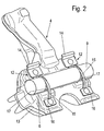
- the application device 3 has a in the Figures 2 and 3 shown as a detail lever 4, which is in operative connection with the brake cylinder 7 and when actuated in the direction of the brake disc 1 is pivotable about a Wälzrolle 9 which is parallel to the plane of the brake disc 2 and is mounted in the bridge 8.
- each roller bearing 11 associated with a cage return 12, according to the invention each formed as separate moldings, attached to the lever 4, preferably riveted, which is particularly clear in the FIG. 2 can be seen.
- the bearing shell 6 has an angled leg 18, on which the angle lug 14 rests firmly, so that the bearing shell 6 is held clamped secured.
Description
- Die Erfindung betrifft eine im Bremssattel einer Scheibenbremse für ein Fahrzeug, insbesondere ein Nutzfahrzeug, angeordnete Zuspanneinrichtung nach dem Oberbegriff des Anspruchs 1.
- Bei einer solchen, vorzugsweise druckluft- oder elektromechanisch betätigbaren und vor allem in Nutzfahrzeuge einbaubaren Scheibenbremse weist die Zuspanneinrichtung einen Hebel, zumindest eine daran befestigte Lagerschale und eine Wälzrolle auf, die parallel zu einer Bremsscheibe verläuft und eine Schwenkachse für den Hebel bildet, wobei die Wälzrolle in der Lagerschale einliegt.
- Zur axialen und radialen Sicherung der Wälzrolle ist in der
EP 1 599 680 B1 ein Halter vorgeschlagen, der an den beiden Stirnseiten der Wälzrolle anliegt und mit dem Hebel durch Warmvernieten verbunden ist. - Dabei ist dieser aus Blech bestehende Halter mit angeformten Käfigrückführungen versehen.
- Aus Festigkeitsgründen ist der Halter wärmebehandelt, wodurch es beim Herstellungsprozess ebenso zu einem Verzug kommen kann, wie durch die funktionsbedingt geometrisch ungünstige Kontur des Käfigrückführungsbleches.
- Naturgemäß ergeben sich dadurch erhebliche fertigungstechnische Nachteile, die einer stets angestrebten Kostenoptimierung entgegenstehen.
- Durch den genannten Verzug des Formteiles ist die Ausschussquote relativ hoch bzw. sind kostenintensive Nacharbeiten erforderlich.
- Im Übrigen steht der Halter aufgrund seines sozusagen Multifunktionscharakters einer gewichtsoptimierten Gestaltung entgegen, wie sie im Fahrzeugbau ständig gefordert wird.
- In der
WO 2006/024512 A1 ist eine Zuspanneinrichtung gemäß der Gattung geoffenbart, bei der die Käfigrückführungen als Bestandteil einer Lagerschale durch Vernieten mit dem Bremshebel verbunden sind. Zur Sicherung der Wälzrolle ist ein Sicherungsmittel in Form einer Klammer oder eines Sicherungsstiftes vorgesehen, die oder der in eine Nut der Wälzrolle eingreift. - Der Erfindung liegt die Aufgabe zugrunde, eine Zuspanneinrichtung der gattungsgemäßen Art so weiterzuentwickeln, dass sie konstruktiv einfacher aufgebaut, kostengünstiger herstellbar sowie gewichtsoptimiert ist.
- Diese Aufgabe wird durch eine Zuspanneinrichtung mit den Merkmalen des Anspruchs 1 gelöst.
- Die in diesem Sinn ausgebildete Zuspanneinrichtung bietet gegenüber der bisher bekannten und eingesetzten wesentliche Vorteile.
- So ist zunächst einmal hervorzuheben, dass durch die jeweils separate Ausbildung der Käfigrückführungen eine derart quasi filigrane Formgebung möglich ist, dass ein Verzug durch die notwendige Wärmebehandlung vermieden wird.
- Darüber hinaus ermöglicht die Erfindung eine Gewichtsoptimierung der Käfigrückführungen bzw. der Halterung zur radialen und axialen Sicherung der Wälzrolle, da sich der Materialeinsatz nur noch auf das tatsächlich Notwendige beschränkt und überdies ausschließlich von den vorherrschenden Belastungsverhältnissen abhängig ist.
- Die Lagerschale wird zweckmäßigerweise durch die Käfigrückführungen eingeklemmt, die im Übrigen mit dem Hebel durch Vernieten verbunden sind.
- Zum Formschluss zwischen der Wälzrolle und der jeweiligen Käfigrückführung ist diese bügelartig geformt und greift dabei in eine Vertiefung der Mantelfläche der Wälzrolle, vorzugsweise eine umlaufende Nut, ein.
- Zur Gewichtseinsparung, die sich aus der Erfindung ergibt, zählt auch der Verzicht auf stirnseitige Zapfen der Wälzrolle, an die der aus dem genannten Stand der Technik bekannte Halter angreift.
- Nach einer vorteilhaften Weiterbildung der Erfindung sind die Käfigrückführungen identisch ausgebildet, was ebenfalls zur Reduzierung der Herstellungskosten beiträgt.
- Die Gestaltung der Käfigrückführungen ermöglicht eine Vergrößerung der Auflagefläche und korrespondierend damit einer Brücke, in der Stellspindeln gelagert sind, mittels derer ein Bremsbelag gegen eine Bremsscheibe pressbar ist. Daraus ergibt sich weiter, dass Gussradien an der als Gussteil ausgebildeten Brücke größer dimensioniert werden können, mit der Folge einer Festigkeitserhöhung der Brücke, die letztendlich gleichfalls zu einer Gewichtsoptimierung beiträgt, da die Brücke bei gleichbleibender Belastung in ihrer Dimensionierung kleiner ausgebildet werden kann.
- Weitere vorteilhafte Ausbildungen der Erfindung sind in den Unteransprüchen gekennzeichnet.
- Ein Ausführungsbeispiel der Erfindung wird nachfolgend anhand der beigefügten Zeichnungen beschrieben.
- Es zeigen:
- Figur 1
- den schematischen Aufbau einer Scheibenbremse in einem Querschnitt
- Figur 2
- einen Teil der Scheibenbremse in einer perspektivischen Ansicht
- Figur 3
- einen Ausschnitt des Teils gemäß der
Figur 2 in einer Seitenansicht - Figur 4
- eine Einzelheit der Scheibenbremse in einer perspektivischen Ansicht.
- In der
Figur 1 ist in schematischer Darstellung eine Scheibenbremse für ein Fahrzeug, insbesondere ein Nutzfahrzeug, in einem Halbschnitt dargestellt, die eine Bremsscheibe 2 aufweist, die an einer nicht gezeigten Achse des Nutzfahrzeuges befestigt ist und von einem Bremssattel 1 umfasst ist, der in Richtung der Bremsscheibe 2 verschiebbar sein kann. - Im Bremssattel 1 ist eine Zuspanneinrichtung 3 angeordnet, mit der bei einer über einen vorzugsweise pneumatisch betätigten Bremszylinder 7 ausgelösten Bremsung Bremsbeläge 10 an die Bremsscheibe 2 drückbar sind.
- Hierzu greift die Zuspanneinrichtung 3 an zwei nicht dargestellte, parallel und mit Abstand zueinander in einer Brücke 8 angeordnete Stellspindeln an.
- Die Zuspanneinrichtung 3 weist einen in den
Figuren 2 und3 als Einzelheit gezeigten Hebel 4 auf, der mit dem Bremszylinder 7 in Wirkverbindung steht und bei dessen Betätigung in Richtung der Bremsscheibe 1 schwenkbar um eine Wälzrolle 9 ist, die parallel zur Ebene der Bremsscheibe 2 verläuft und in der Brücke 8 gelagert ist. - Im Bremssattel 1 sind Wälzlager 11 vorgesehen, mit jeweils in einem Käfig gehaltenen Wälzkörpern, die sich an dem in diesem Bereich als Exzenter 13 ausgebildeten Hebel 4 abstützen. Die Wälzrolle 9 ist am Hebel 4 axial und radial gesichert gehalten.
- Dabei stützt sich die Wälzrolle 9 andererseits an einer Lagerschale 6 ab, die in einer im Exzenter 13, dem Wälzlager 11 gegenüberliegend, eingebrachten konkaven Kehle 5 einliegt.
- Um die Wälzlager 11 nach einer Zurückschwenkung des Hebels 4 in eine Ausgangsstellung zurückzuführen, ist jedem Wälzlager 11 zugeordnet eine Käfigrückführung 12, erfindungsgemäß jeweils als separate Formteile ausgebildet, am Hebel 4 befestigt, vorzugsweise vernietet, was besonders deutlich in der
Figur 2 zu erkennen ist. - In der
Figur 4 ist erkennbar, dass die Käfigrückführung aus einer Winkellasche 14, einer Lasche 16 sowie einem beide miteinander verbindenden bogenförmigen Steg 15 besteht, wobei die Winkellasche 14 einen Anschlag für den Käfig des Wälzlagers 11 bildet und damit der eigentlichen Käfigrückführung dient, aber ebenso wie die Lasche 16 als Verbindungselement mit dem Hebel 4, wobei jeweils eine Bohrung zur Durchführung des Niets vorgesehen ist. - Die radiale und axiale Sicherung der Wälzrolle 9 erfolgt durch formschlüssigen Eingriff der Käfigrückführungen 12, wozu die Wälzrolle 9 umlaufende Nuten 17 aufweist, in denen die in ihren Querschnittsabmaßen daran angepassten Stege 15 einliegen.
- In der
Figur 3 ist erkennbar, dass die Lagerschale 6 einen abgewinkelten Schenkel 18 aufweist, auf dem die Winkellasche 14 fest aufliegt, so dass die Lagerschale 6 klemmend gesichert gehalten ist. -
- 1
- Bremssattel
- 2
- Bremsscheibe
- 3
- Zuspanneinrichtung
- 4
- Hebel
- 5
- Kehle
- 6
- Lagerschale
- 7
- Bremszylinder
- 8
- Brücke
- 9
- Wälzrolle
- 10
- Bremsbelag
- 11
- Wälzlager
- 12
- Käfigrückführung
- 13
- Exzenter
- 14
- Winkellasche
- 15
- Steg
- 16
- Lasche
- 17
- Nut
- 18
- Schenkel
Claims (9)
- Zuspanneinrichtung (3) für einen Bremssattel (1) einer Scheibenbremse für ein Fahrzeug,
die eine axial und radial gesicherte, sich in einer Lagerschale (6) eines im Abstützbereich mit jeweils in einem Käfig gehaltenen, Wälzkörper aufweisenden Wälzlagern (11) des Bremssattels (1) als Exzenter (13) ausgebildeten schwenkbaren Hebels (4) der Zuspanneinrichtung abstützende Wälzrolle (9) aufweist, wobei an dem Hebel (4) ortsfeste Käfigrückführungen (12) angeordnet sind, dadurch gekennzeichnet, dass die Käfigrückführungen (12) aus zwei separaten Formteilen bestehen, die jeweils formschlüssig in die Mantelfläche der Wälzrolle (9) eingreifen. - Zuspanneinrichtung nach Anspruch 1, dadurch gekennzeichnet, dass die Wälzrolle (9), jeder Käfigrückführung (12) zugeordnet, eine Vertiefung, vorzugsweise eine Nut (17) aufweist, in der ein Steg (15) der Käfigrückführung (12) einliegt.
- Zuspanneinrichtung nach Anspruch 2, dadurch gekennzeichnet, dass an einem Ende des bogenförmigen Steges (15) eine Winkellasche (14) und am anderen Ende eine Lasche (16) angeordnet sind, zur Verbindung der Käfigrückführung (12) mit dem Hebel (4).
- Zuspanneinrichtung nach einem der vorhergehenden Ansprüche, dadurch gekennzeichnet, dass die Käfigrückführungen (12) mit dem Hebel (4) vernietet sind.
- Zuspanneinrichtung nach Anspruch 3, dadurch gekennzeichnet, dass die Lagerschale (6) durch die Winkellasche (14) klemmend gehalten ist.
- Zuspanneinrichtung nach einem der Ansprüche 3 oder 5, dadurch gekennzeichnet, dass die Winkellasche (14) einen Anschlag für den Käfig des Wälzlagers (11) bildet.
- Zuspanneinrichtung nach einem der vorhergehenden Ansprüche, dadurch gekennzeichnet, dass die Käfigrückführungen (12) identisch ausgebildet sind.
- Zuspanneinrichtung nach einem der vorhergehenden Ansprüche, dadurch gekennzeichnet, dass die Käfigrückführungen (12) als Blechformteile ausgebildet sind.
- Zuspanneinrichtung nach einem der Ansprüche 3, 5 oder 6, dadurch gekennzeichnet, dass die Lagerschale (6) einen abgewinkelten Schenkel aufweist, auf dem die Winkellasche (14) unter Pressdruck anliegt.
Applications Claiming Priority (1)
| Application Number | Priority Date | Filing Date | Title |
|---|---|---|---|
| DE102010019471A DE102010019471A1 (de) | 2010-05-05 | 2010-05-05 | Im Bremssattel einer Scheibenbremse angeordnete Zuspanneinrichtung |
Publications (2)
| Publication Number | Publication Date |
|---|---|
| EP2385268A1 EP2385268A1 (de) | 2011-11-09 |
| EP2385268B1 true EP2385268B1 (de) | 2013-03-13 |
Family
ID=44510111
Family Applications (1)
| Application Number | Title | Priority Date | Filing Date |
|---|---|---|---|
| EP20110164754 Active EP2385268B1 (de) | 2010-05-05 | 2011-05-04 | Im Bremssattel einer Scheibenbremse angeordnete Zuspanneinrichtung |
Country Status (2)
| Country | Link |
|---|---|
| EP (1) | EP2385268B1 (de) |
| DE (1) | DE102010019471A1 (de) |
Families Citing this family (4)
| Publication number | Priority date | Publication date | Assignee | Title |
|---|---|---|---|---|
| DE102010044911A1 (de) * | 2010-09-09 | 2012-03-15 | Knorr-Bremse Systeme für Nutzfahrzeuge GmbH | Im Bremssattel einer Scheibenbremse angeordnete Zuspanneinrichtung |
| DE102014115762A1 (de) * | 2014-10-30 | 2016-05-04 | Knorr-Bremse Systeme für Nutzfahrzeuge GmbH | Scheibenbremse für ein Nutzfahrzeug |
| GB2563081A (en) * | 2017-06-02 | 2018-12-05 | Meritor Heavy Vehicle Braking Systems Uk Ltd | A brake pad |
| CN113638966B (zh) * | 2021-08-12 | 2023-01-17 | 隆中控股集团股份有限公司 | 一种杠杆和盘式制动器 |
Family Cites Families (6)
| Publication number | Priority date | Publication date | Assignee | Title |
|---|---|---|---|---|
| DE4215200C2 (de) * | 1992-05-08 | 1999-10-21 | Perrot Bremse Gmbh Deutsche | Betätigungsvorrichtung für eine Gleitsattel-Scheibenbremse |
| DE59508013D1 (de) * | 1994-01-18 | 2000-04-20 | Meritor Automotive Inc | Zuspannvorrichtung einer Scheibenbremse, insbesondere für schwere Nutzfahrzeuge |
| DE59603789D1 (de) * | 1995-05-15 | 2000-01-05 | Meritor Automotive Inc | Zuspannvorrichtung einer scheibenbremse |
| DE10307734B3 (de) | 2003-02-24 | 2004-09-30 | Knorr-Bremse Systeme für Nutzfahrzeuge GmbH | Scheibenbremse für ein Fahrzeug, insbesondere ein Nutzfahrzeug |
| DE102004042576A1 (de) * | 2004-09-02 | 2006-03-30 | Knorr-Bremse Systeme für Nutzfahrzeuge GmbH | Scheibenbremse für ein Fahrzeug, insbesondere ein Nutzfahrzeug |
| DE102008029315A1 (de) * | 2008-06-20 | 2009-12-24 | Knorr-Bremse Systeme für Nutzfahrzeuge GmbH | Bremssattel einer Scheibenbremse angeordnete Zuspanneinrichtung |
-
2010
- 2010-05-05 DE DE102010019471A patent/DE102010019471A1/de not_active Ceased
-
2011
- 2011-05-04 EP EP20110164754 patent/EP2385268B1/de active Active
Also Published As
| Publication number | Publication date |
|---|---|
| EP2385268A1 (de) | 2011-11-09 |
| DE102010019471A1 (de) | 2011-11-10 |
Similar Documents
| Publication | Publication Date | Title |
|---|---|---|
| EP3359842B2 (de) | Scheibenbremse für ein nutzfahrzeug | |
| EP1599680B1 (de) | Scheibenbremse für ein fahrzeug, insbesondere ein nutzfahrzeug | |
| EP1789695B1 (de) | Scheibenbremse für ein fahrzeug, insbesondere ein nutzfahrzeug | |
| EP3149353B2 (de) | Scheibenbremse, bremssattel und bremsbelagsatz für eine scheibenbremse | |
| EP2831457B1 (de) | Bremsbelaganordnung für eine schiebesattel-scheibenbremse | |
| EP3237773B1 (de) | Scheibenbremse für ein nutzfahrzeug | |
| DE102008027052A1 (de) | Scheibenbremse für ein Nutzfahrzeug | |
| EP2385268B1 (de) | Im Bremssattel einer Scheibenbremse angeordnete Zuspanneinrichtung | |
| EP2428695B1 (de) | Im Bremssattel einer Scheibenbremse angeordnete Zuspanneinrichtung | |
| EP1825164B1 (de) | Scheibenbremse für ein fahrzeug | |
| EP3027926B1 (de) | Scheibenbremse, insbesondere für nutzfahrzeuge, sowie bremsbelag einer solchen scheibenbremse | |
| DE102012003104B4 (de) | Im Bremssattel einer Scheibenbremse angeordnete Zuspanneinrichtung | |
| DE102012110458A1 (de) | Scheibenbremse für ein Nutzfahrzeug | |
| DE102007023191A1 (de) | Scheibenbremse für ein Nutzfahrzeug | |
| EP1819936B1 (de) | Scheibenbremse für ein fahrzeug | |
| EP2847483B1 (de) | Scheibenbremse für ein nutzfahrzeug | |
| DE102015108304A1 (de) | Scheibenbremse, und Bremsbelagsatz für eine Scheibenbremse | |
| DE10150214B4 (de) | Scheibenbremse, insbesondere für ein Nutzfahrzeug | |
| DE102016111041B4 (de) | Scheibenbremse für ein Nutzfahrzeug | |
| EP3390852A1 (de) | Schwimmsattel-scheibenbremse | |
| DE4343737B4 (de) | Scheibenbremse | |
| WO2022063516A1 (de) | Zuspanneinrichtung einer scheibenbremse | |
| DE202010005051U1 (de) | Scheibenbremse mit querkraftentkoppeltem Druckstück |
Legal Events
| Date | Code | Title | Description |
|---|---|---|---|
| AK | Designated contracting states |
Kind code of ref document: A1 Designated state(s): AL AT BE BG CH CY CZ DE DK EE ES FI FR GB GR HR HU IE IS IT LI LT LU LV MC MK MT NL NO PL PT RO RS SE SI SK SM TR |
|
| AX | Request for extension of the european patent |
Extension state: BA ME |
|
| PUAI | Public reference made under article 153(3) epc to a published international application that has entered the european phase |
Free format text: ORIGINAL CODE: 0009012 |
|
| 17P | Request for examination filed |
Effective date: 20120509 |
|
| GRAP | Despatch of communication of intention to grant a patent |
Free format text: ORIGINAL CODE: EPIDOSNIGR1 |
|
| RIN1 | Information on inventor provided before grant (corrected) |
Inventor name: BRANDL, CHRISTIAN |
|
| GRAS | Grant fee paid |
Free format text: ORIGINAL CODE: EPIDOSNIGR3 |
|
| GRAA | (expected) grant |
Free format text: ORIGINAL CODE: 0009210 |
|
| AK | Designated contracting states |
Kind code of ref document: B1 Designated state(s): AL AT BE BG CH CY CZ DE DK EE ES FI FR GB GR HR HU IE IS IT LI LT LU LV MC MK MT NL NO PL PT RO RS SE SI SK SM TR |
|
| REG | Reference to a national code |
Ref country code: GB Ref legal event code: FG4D Free format text: NOT ENGLISH |
|
| REG | Reference to a national code |
Ref country code: CH Ref legal event code: EP Ref country code: AT Ref legal event code: REF Ref document number: 600987 Country of ref document: AT Kind code of ref document: T Effective date: 20130315 |
|
| REG | Reference to a national code |
Ref country code: IE Ref legal event code: FG4D Free format text: LANGUAGE OF EP DOCUMENT: GERMAN |
|
| REG | Reference to a national code |
Ref country code: DE Ref legal event code: R096 Ref document number: 502011000468 Country of ref document: DE Effective date: 20130508 |
|
| REG | Reference to a national code |
Ref country code: SE Ref legal event code: TRGR |
|
| PG25 | Lapsed in a contracting state [announced via postgrant information from national office to epo] |
Ref country code: BG Free format text: LAPSE BECAUSE OF FAILURE TO SUBMIT A TRANSLATION OF THE DESCRIPTION OR TO PAY THE FEE WITHIN THE PRESCRIBED TIME-LIMIT Effective date: 20130613 Ref country code: LT Free format text: LAPSE BECAUSE OF FAILURE TO SUBMIT A TRANSLATION OF THE DESCRIPTION OR TO PAY THE FEE WITHIN THE PRESCRIBED TIME-LIMIT Effective date: 20130313 Ref country code: NO Free format text: LAPSE BECAUSE OF FAILURE TO SUBMIT A TRANSLATION OF THE DESCRIPTION OR TO PAY THE FEE WITHIN THE PRESCRIBED TIME-LIMIT Effective date: 20130613 Ref country code: ES Free format text: LAPSE BECAUSE OF FAILURE TO SUBMIT A TRANSLATION OF THE DESCRIPTION OR TO PAY THE FEE WITHIN THE PRESCRIBED TIME-LIMIT Effective date: 20130624 |
|
| REG | Reference to a national code |
Ref country code: NL Ref legal event code: VDEP Effective date: 20130313 |
|
| REG | Reference to a national code |
Ref country code: LT Ref legal event code: MG4D |
|
| PG25 | Lapsed in a contracting state [announced via postgrant information from national office to epo] |
Ref country code: GR Free format text: LAPSE BECAUSE OF FAILURE TO SUBMIT A TRANSLATION OF THE DESCRIPTION OR TO PAY THE FEE WITHIN THE PRESCRIBED TIME-LIMIT Effective date: 20130614 Ref country code: FI Free format text: LAPSE BECAUSE OF FAILURE TO SUBMIT A TRANSLATION OF THE DESCRIPTION OR TO PAY THE FEE WITHIN THE PRESCRIBED TIME-LIMIT Effective date: 20130313 Ref country code: SI Free format text: LAPSE BECAUSE OF FAILURE TO SUBMIT A TRANSLATION OF THE DESCRIPTION OR TO PAY THE FEE WITHIN THE PRESCRIBED TIME-LIMIT Effective date: 20130313 Ref country code: LV Free format text: LAPSE BECAUSE OF FAILURE TO SUBMIT A TRANSLATION OF THE DESCRIPTION OR TO PAY THE FEE WITHIN THE PRESCRIBED TIME-LIMIT Effective date: 20130313 |
|
| PG25 | Lapsed in a contracting state [announced via postgrant information from national office to epo] |
Ref country code: RS Free format text: LAPSE BECAUSE OF FAILURE TO SUBMIT A TRANSLATION OF THE DESCRIPTION OR TO PAY THE FEE WITHIN THE PRESCRIBED TIME-LIMIT Effective date: 20130313 Ref country code: HR Free format text: LAPSE BECAUSE OF FAILURE TO SUBMIT A TRANSLATION OF THE DESCRIPTION OR TO PAY THE FEE WITHIN THE PRESCRIBED TIME-LIMIT Effective date: 20130313 |
|
| PG25 | Lapsed in a contracting state [announced via postgrant information from national office to epo] |
Ref country code: IS Free format text: LAPSE BECAUSE OF FAILURE TO SUBMIT A TRANSLATION OF THE DESCRIPTION OR TO PAY THE FEE WITHIN THE PRESCRIBED TIME-LIMIT Effective date: 20130713 Ref country code: RO Free format text: LAPSE BECAUSE OF FAILURE TO SUBMIT A TRANSLATION OF THE DESCRIPTION OR TO PAY THE FEE WITHIN THE PRESCRIBED TIME-LIMIT Effective date: 20130313 Ref country code: CZ Free format text: LAPSE BECAUSE OF FAILURE TO SUBMIT A TRANSLATION OF THE DESCRIPTION OR TO PAY THE FEE WITHIN THE PRESCRIBED TIME-LIMIT Effective date: 20130313 Ref country code: SK Free format text: LAPSE BECAUSE OF FAILURE TO SUBMIT A TRANSLATION OF THE DESCRIPTION OR TO PAY THE FEE WITHIN THE PRESCRIBED TIME-LIMIT Effective date: 20130313 Ref country code: PT Free format text: LAPSE BECAUSE OF FAILURE TO SUBMIT A TRANSLATION OF THE DESCRIPTION OR TO PAY THE FEE WITHIN THE PRESCRIBED TIME-LIMIT Effective date: 20130715 Ref country code: EE Free format text: LAPSE BECAUSE OF FAILURE TO SUBMIT A TRANSLATION OF THE DESCRIPTION OR TO PAY THE FEE WITHIN THE PRESCRIBED TIME-LIMIT Effective date: 20130313 Ref country code: NL Free format text: LAPSE BECAUSE OF FAILURE TO SUBMIT A TRANSLATION OF THE DESCRIPTION OR TO PAY THE FEE WITHIN THE PRESCRIBED TIME-LIMIT Effective date: 20130313 |
|
| PG25 | Lapsed in a contracting state [announced via postgrant information from national office to epo] |
Ref country code: PL Free format text: LAPSE BECAUSE OF FAILURE TO SUBMIT A TRANSLATION OF THE DESCRIPTION OR TO PAY THE FEE WITHIN THE PRESCRIBED TIME-LIMIT Effective date: 20130313 |
|
| BERE | Be: lapsed |
Owner name: KNORR-BREMSE SYSTEME FUR NUTZFAHRZEUGE G.M.B.H. Effective date: 20130531 |
|
| PG25 | Lapsed in a contracting state [announced via postgrant information from national office to epo] |
Ref country code: MC Free format text: LAPSE BECAUSE OF FAILURE TO SUBMIT A TRANSLATION OF THE DESCRIPTION OR TO PAY THE FEE WITHIN THE PRESCRIBED TIME-LIMIT Effective date: 20130313 |
|
| PLBE | No opposition filed within time limit |
Free format text: ORIGINAL CODE: 0009261 |
|
| STAA | Information on the status of an ep patent application or granted ep patent |
Free format text: STATUS: NO OPPOSITION FILED WITHIN TIME LIMIT |
|
| PG25 | Lapsed in a contracting state [announced via postgrant information from national office to epo] |
Ref country code: DK Free format text: LAPSE BECAUSE OF FAILURE TO SUBMIT A TRANSLATION OF THE DESCRIPTION OR TO PAY THE FEE WITHIN THE PRESCRIBED TIME-LIMIT Effective date: 20130313 |
|
| 26N | No opposition filed |
Effective date: 20131216 |
|
| REG | Reference to a national code |
Ref country code: IE Ref legal event code: MM4A |
|
| PG25 | Lapsed in a contracting state [announced via postgrant information from national office to epo] |
Ref country code: BE Free format text: LAPSE BECAUSE OF NON-PAYMENT OF DUE FEES Effective date: 20130531 |
|
| REG | Reference to a national code |
Ref country code: FR Ref legal event code: ST Effective date: 20140131 |
|
| REG | Reference to a national code |
Ref country code: DE Ref legal event code: R097 Ref document number: 502011000468 Country of ref document: DE Effective date: 20131216 |
|
| PG25 | Lapsed in a contracting state [announced via postgrant information from national office to epo] |
Ref country code: IE Free format text: LAPSE BECAUSE OF NON-PAYMENT OF DUE FEES Effective date: 20130504 |
|
| PG25 | Lapsed in a contracting state [announced via postgrant information from national office to epo] |
Ref country code: FR Free format text: LAPSE BECAUSE OF NON-PAYMENT OF DUE FEES Effective date: 20130531 |
|
| REG | Reference to a national code |
Ref country code: CH Ref legal event code: PL |
|
| PG25 | Lapsed in a contracting state [announced via postgrant information from national office to epo] |
Ref country code: LI Free format text: LAPSE BECAUSE OF NON-PAYMENT OF DUE FEES Effective date: 20140531 Ref country code: CH Free format text: LAPSE BECAUSE OF NON-PAYMENT OF DUE FEES Effective date: 20140531 |
|
| PG25 | Lapsed in a contracting state [announced via postgrant information from national office to epo] |
Ref country code: MT Free format text: LAPSE BECAUSE OF FAILURE TO SUBMIT A TRANSLATION OF THE DESCRIPTION OR TO PAY THE FEE WITHIN THE PRESCRIBED TIME-LIMIT Effective date: 20130313 |
|
| PG25 | Lapsed in a contracting state [announced via postgrant information from national office to epo] |
Ref country code: SM Free format text: LAPSE BECAUSE OF FAILURE TO SUBMIT A TRANSLATION OF THE DESCRIPTION OR TO PAY THE FEE WITHIN THE PRESCRIBED TIME-LIMIT Effective date: 20130313 |
|
| PG25 | Lapsed in a contracting state [announced via postgrant information from national office to epo] |
Ref country code: TR Free format text: LAPSE BECAUSE OF FAILURE TO SUBMIT A TRANSLATION OF THE DESCRIPTION OR TO PAY THE FEE WITHIN THE PRESCRIBED TIME-LIMIT Effective date: 20130313 Ref country code: CY Free format text: LAPSE BECAUSE OF FAILURE TO SUBMIT A TRANSLATION OF THE DESCRIPTION OR TO PAY THE FEE WITHIN THE PRESCRIBED TIME-LIMIT Effective date: 20130313 |
|
| PG25 | Lapsed in a contracting state [announced via postgrant information from national office to epo] |
Ref country code: MK Free format text: LAPSE BECAUSE OF FAILURE TO SUBMIT A TRANSLATION OF THE DESCRIPTION OR TO PAY THE FEE WITHIN THE PRESCRIBED TIME-LIMIT Effective date: 20130313 Ref country code: HU Free format text: LAPSE BECAUSE OF FAILURE TO SUBMIT A TRANSLATION OF THE DESCRIPTION OR TO PAY THE FEE WITHIN THE PRESCRIBED TIME-LIMIT; INVALID AB INITIO Effective date: 20110504 Ref country code: LU Free format text: LAPSE BECAUSE OF NON-PAYMENT OF DUE FEES Effective date: 20130504 |
|
| PGFP | Annual fee paid to national office [announced via postgrant information from national office to epo] |
Ref country code: GB Payment date: 20150521 Year of fee payment: 5 Ref country code: SE Payment date: 20150521 Year of fee payment: 5 |
|
| PGFP | Annual fee paid to national office [announced via postgrant information from national office to epo] |
Ref country code: IT Payment date: 20150519 Year of fee payment: 5 |
|
| GBPC | Gb: european patent ceased through non-payment of renewal fee |
Effective date: 20160504 |
|
| PG25 | Lapsed in a contracting state [announced via postgrant information from national office to epo] |
Ref country code: IT Free format text: LAPSE BECAUSE OF NON-PAYMENT OF DUE FEES Effective date: 20160504 Ref country code: SE Free format text: LAPSE BECAUSE OF NON-PAYMENT OF DUE FEES Effective date: 20160505 |
|
| PG25 | Lapsed in a contracting state [announced via postgrant information from national office to epo] |
Ref country code: GB Free format text: LAPSE BECAUSE OF NON-PAYMENT OF DUE FEES Effective date: 20160504 |
|
| REG | Reference to a national code |
Ref country code: AT Ref legal event code: MM01 Ref document number: 600987 Country of ref document: AT Kind code of ref document: T Effective date: 20160504 |
|
| PG25 | Lapsed in a contracting state [announced via postgrant information from national office to epo] |
Ref country code: AT Free format text: LAPSE BECAUSE OF NON-PAYMENT OF DUE FEES Effective date: 20160504 |
|
| PG25 | Lapsed in a contracting state [announced via postgrant information from national office to epo] |
Ref country code: AL Free format text: LAPSE BECAUSE OF FAILURE TO SUBMIT A TRANSLATION OF THE DESCRIPTION OR TO PAY THE FEE WITHIN THE PRESCRIBED TIME-LIMIT Effective date: 20130313 |
|
| P01 | Opt-out of the competence of the unified patent court (upc) registered |
Effective date: 20230607 |
|
| PGFP | Annual fee paid to national office [announced via postgrant information from national office to epo] |
Ref country code: DE Payment date: 20230519 Year of fee payment: 13 |