EP2385257A2 - Vakuumpumpstufe - Google Patents
Vakuumpumpstufe Download PDFInfo
- Publication number
- EP2385257A2 EP2385257A2 EP11002911A EP11002911A EP2385257A2 EP 2385257 A2 EP2385257 A2 EP 2385257A2 EP 11002911 A EP11002911 A EP 11002911A EP 11002911 A EP11002911 A EP 11002911A EP 2385257 A2 EP2385257 A2 EP 2385257A2
- Authority
- EP
- European Patent Office
- Prior art keywords
- channel
- vacuum
- rotor
- design
- pumping stage
- Prior art date
- Legal status (The legal status is an assumption and is not a legal conclusion. Google has not performed a legal analysis and makes no representation as to the accuracy of the status listed.)
- Granted
Links
- 238000005086 pumping Methods 0.000 claims abstract description 46
- 238000013461 design Methods 0.000 claims abstract description 22
- 238000004891 communication Methods 0.000 claims description 2
- 230000003993 interaction Effects 0.000 claims 1
- 230000006835 compression Effects 0.000 description 13
- 238000007906 compression Methods 0.000 description 13
- 238000011161 development Methods 0.000 description 9
- 230000018109 developmental process Effects 0.000 description 9
- 230000008901 benefit Effects 0.000 description 4
- 238000004519 manufacturing process Methods 0.000 description 3
- 230000007704 transition Effects 0.000 description 2
- 230000000712 assembly Effects 0.000 description 1
- 238000000429 assembly Methods 0.000 description 1
- 230000001419 dependent effect Effects 0.000 description 1
- 230000000694 effects Effects 0.000 description 1
- 230000002349 favourable effect Effects 0.000 description 1
- 239000004519 grease Substances 0.000 description 1
- 239000000314 lubricant Substances 0.000 description 1
- 238000005259 measurement Methods 0.000 description 1
- 239000007787 solid Substances 0.000 description 1
Images
Classifications
-
- F—MECHANICAL ENGINEERING; LIGHTING; HEATING; WEAPONS; BLASTING
- F04—POSITIVE - DISPLACEMENT MACHINES FOR LIQUIDS; PUMPS FOR LIQUIDS OR ELASTIC FLUIDS
- F04D—NON-POSITIVE-DISPLACEMENT PUMPS
- F04D23/00—Other rotary non-positive-displacement pumps
- F04D23/008—Regenerative pumps
-
- F—MECHANICAL ENGINEERING; LIGHTING; HEATING; WEAPONS; BLASTING
- F04—POSITIVE - DISPLACEMENT MACHINES FOR LIQUIDS; PUMPS FOR LIQUIDS OR ELASTIC FLUIDS
- F04D—NON-POSITIVE-DISPLACEMENT PUMPS
- F04D17/00—Radial-flow pumps, e.g. centrifugal pumps; Helico-centrifugal pumps
- F04D17/08—Centrifugal pumps
- F04D17/16—Centrifugal pumps for displacing without appreciable compression
- F04D17/168—Pumps specially adapted to produce a vacuum
-
- F—MECHANICAL ENGINEERING; LIGHTING; HEATING; WEAPONS; BLASTING
- F04—POSITIVE - DISPLACEMENT MACHINES FOR LIQUIDS; PUMPS FOR LIQUIDS OR ELASTIC FLUIDS
- F04D—NON-POSITIVE-DISPLACEMENT PUMPS
- F04D19/00—Axial-flow pumps
- F04D19/02—Multi-stage pumps
- F04D19/04—Multi-stage pumps specially adapted to the production of a high vacuum, e.g. molecular pumps
- F04D19/046—Combinations of two or more different types of pumps
Definitions
- the invention relates to a vacuum pumping stage according to the preamble of the first claim.
- Vacuum pumps or vacuum pump assemblies composed of vacuum pumps are used to generate such vacuum conditions.
- vacuum pump stages are used according to different principles of action, which are adapted to different pressure ranges to compress gas from the desired final vacuum to the atmosphere.
- side channel pumping stages are used to compress the atmosphere.
- These blades run around in a channel and promote a vortex-like gas flow between inlet and outlet.
- the gas stream follows the blades during circulation and is removed at a so-called scraper and fed to the outlet.
- the disadvantage is that designed according to this principle pumping stages operate only in the viscous flow area and lose the transition to the molecular flow very quickly compression and pumping, since no vortex-like gas flow can be generated more.
- Gaedepump stages are used inter alia in the molecular range adjacent to the viscous flow region at lower absolute pressures. Their drawback is that compression and absorbency are good only under molecular conditions and become poor very quickly in the viscous region.
- the object of the invention was therefore to provide a vacuum pumping stage, which provides compression and pumping both in the viscous and in the molecular flow area.
- the vacuum pumping stage having the features of the first claim provides compression and suction in both the viscous and molecular flow regime. It can therefore be used advantageously in both flow regions and in the transition region between them.
- the vacuum pump according to claims 6 and 7 is characterized by an advantageous power consumption, which is lower compared to vacuum pumping stages with Gaede- or side channel stages due to the compression curve and the pumping speed characteristic.
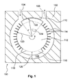
- the vacuum pumping stage 100 after FIG. 1 has a housing 102.
- an inlet 104 is provided, is sucked through the gas in the vacuum pumping stage.
- an outlet 106 the pumped within the vacuum pumping stage gas is ejected.
- Inlet and outlet are interconnected by a channel 108.
- a rotatably arranged in the housing rotor 112 dives with a rotor portion, wherein channel and rotor portion cooperate to generate the pumping action.
- the rotor section comprises that part of the rotor which, viewed in the radial direction from the axis of rotation of the rotor, projects beyond the inner boundary 118 of the channel into the channel.
- the smooth section is through a zone of the rotor is formed, which projects beyond the outer surface radius 122 over the blade root radius 120 and extends along the circumference over an angular range 124.
- the blade root radius is substantially close to the radius of the inner boundary of the channel.
- the outer radius is chosen so that on the one hand only a small gap to a scraper remains, on the other hand, only a portion of the channel depth 126 is utilized.
- the scraper separates the gas flow entrained at the rotor section and prevents a direct flow between inlet and outlet.
- the smooth section creates together with the channel in the molecular flow area compression and pumping speed and acts on the Gaedezin.
- the vanes 114 act in the viscous flow area as side channel pumping structures which cooperate with the channel.
- smooth sections are distributed over the circumference of the rotor, resulting in a mass balance. This is achieved for example by two opposite smooth sections. Furthermore, this design can be advantageously further developed by blades and smooth sections are dimensioned so that in each case opposite masses correspond in value.
- the channel is not arranged as shown in the disk plane but axially offset thereto.
- the blades and the smooth section are then out of the plane of the drawing.
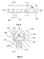
- FIG. 2 Channel and rotor section are shown in a development
- Fig. 3 shows the section along the line I-I '.
- the channel 208 is provided with a channel depth 226. Beyond the inner boundary 218 of the channel, the rotor section projects into the channel. In it are provided as design elements blades 214 which rotate by rotation of the rotor in the channel. The blades have a thickness 228 in the direction of movement. At least one of the blades has a thickness greater than about one fifth of the distance 230 to the succeeding blade. It is achieved by this thickness that the blade surfaces 250, 252 and 254 facing the channel walls 240, 242 and 244 act in the molecular flow region like gas pumping structures. In the viscous flow region, the rotor section acts as a side channel pumping stage due to the blades.
- the channel may also, as already mentioned in the other two examples, be offset axially relative to the plane of the rotor 234.
- the design elements are then arranged in the figure left or right next to the rotor.
- At least one blade (214) has a thickness which is equal to or greater than approximately the distance (230) to the subsequent blade.
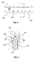
- FIGS. 4 and 5 Another embodiment is in the FIGS. 4 and 5 shown.
- Fig. 4 Channel and rotor section are shown in a development,
- Fig. 5 shows the section along the line II-II '.
- the channel 308 is provided here, which is bounded by the inner boundary 318 in the direction of the axis of rotation.
- blades 314 are provided as design elements which lead to a side channel pumping action in the viscous flow area.
- the rotor section also has a base land 340 which projects beyond the inner boundary into the channel.
- FIG. 5 It is shown that the base web protrudes with the web height 332 over the inner boundary.
- the side surface 342 of the base bar This works together with the channel wall in the molecular flow area as Gaedepumplay.
- the channel may also, as already mentioned in the other two examples, be offset axially relative to the plane of the rotor 334.
- the design elements are then arranged in the figure left or right next to the rotor.
- the design elements ie the base web and blades, lie in the plane 334 of the disk-like rotor 312, as a result of which the rotor-dynamic properties are improved.
- the base web is provided only along part of the circumference of the rotor.
- a base web with the thicker blades and / or a smooth section can be used together to achieve design elements in the rotor section, by means of which the pumping action in the molecular flow region is effected according to Gaede and in the higher pressure range according to the side channel principle.
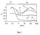
- Curve 70 shows the course for a pure Gaedepumpcut. There is a strong increase in the molecular flow area observed, while at higher pressures, especially above 1 hPa, no significant compression occurs.
- Curve 72 shows the course of a pure side channel pumping stage. Here the compression reaches its maximum towards higher pressures.
- Curve 74 shows the compression curve for the smooth-section embodiment FIG. 1
- Curve 76 traces the course for the embodiment with thick blades FIGS. 2 and 3 ,
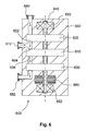
- a vacuum pump 600 is shown in the basic structure, in which the advantages of the vacuum pumping stage described above are particularly good advantage.
- a shaft 640 is provided, which is rotatably supported by bearings 650 and 652.
- bearings 650 and 652. may be grease or oil lubricated bearings, gas, sliding or magnetic bearings. These types of bearings can be mixed, with lubricants such as oil or the like can be used in the area of the preliminary vacuum, which can be found on the side of the bearing 652.
- This is advantageously designed as a Holweck or turbomolecular pumping stage and can itself be constructed in several stages. Different pumping principles can be used in these individual stages.
- the inlet 604 is in gas flow communication with a suction port 612 so that the multi-section stage 610 sucks gas through both this suction port and the high vacuum pump stage outlet 622.
- the compressed gas in it is expelled through the outlet 606 and fed to a fore-vacuum stage 630.
- This can advantageously be designed as a side channel pumping stage and in turn comprise a plurality of pumping stages.
- a pump outlet 682 the gas is expelled from the vacuum pump, for example against the atmosphere or in the supply line to a backing pump.
- the pumping stages 610, 620 and 630 are commonly driven by the drive means 660.
- the multigrade stage advantageously operates in a pressure and flow regime in which it possesses better compression and absorbency properties per power consumed than pure Gaede or side channel pumping stages.
Landscapes
- Engineering & Computer Science (AREA)
- Mechanical Engineering (AREA)
- General Engineering & Computer Science (AREA)
- Non-Positive Displacement Air Blowers (AREA)
- Applications Or Details Of Rotary Compressors (AREA)
Abstract
Description
- Die Erfindung betrifft eine Vakuumpumpstufe nach dem Oberbegriff des ersten Anspruchs.
- Viele industrielle Prozesse laufen unter Vakuumbedingungen im molekularen Strömungsbereich ab. Zur Erzeugung solcher Vakuumbedingungen werden Vakuumpumpen oder aus Vakuumpumpen zusammengesetzte Vakuumpumpstände eingesetzt. In den Vakuumpumpen kommen Vakuumpumpstufen nach unterschiedlichen Wirkprinzipien zum Einsatz, die unterschiedlichen Druckbereichen angepasst sind, um Gas vom gewünschten Endvakuum bis zur Atmosphäre zu verdichten.
- Gegen Atmosphäre verdichtend werden beispielsweise Seitenkanalpumpstufen eingesetzt. In diesen laufen Schaufeln in einem Kanal um und fördern einen wirbelartigen Gasstrom zwischen Ein- und Auslass. Der Gasstrom folgt den Schaufeln beim Umlauf und wird an einem sogenannten Abstreifer abgelöst und dem Auslass zugeführt. Nachteilig ist, dass nach diesem Prinzip gestaltete Pumpstufen lediglich im viskosen Strömungsbereich arbeiten und beim Übergang zur molekularen Strömung sehr schnell Kompression und Saugvermögen verlieren, da kein wirbelartiger Gasstrom mehr erzeugt werden kann.
- Im zu niedrigeren Absolutdrücken an den viskosen Strömungsbereich angrenzenden Molekularbereich werden unter anderem Gaedepumpstufen eingesetzt. Deren Nachteil ist, dass Kompression und Saugvermögen lediglich unter molekularen Bedingungen gut sind und im viskosen Bereich sehr schnell schlecht werden.
- Die vorgenannten Nachteile werden verschärft, da Vakuumpumpen oft im Zyklusbetrieb eingesetzt werden, so dass die einzelnen Pumpstufen auf die Gesamtbetriebsdauer gesehen oft in einem Strömungsbereich arbeiten, für den sie nicht optimiert sind.
- Aufgabe der Erfindung war es daher, eine Vakuumpumpstufe zu schaffen, die sowohl im viskosen als auch im molekularen Strömungsbereich Kompression und Saugvermögen bereitstellt.
- Gelöst wird diese Aufgabe durch eine Vakuumpumpstufe mit den Merkmalen des ersten Patentanspruchs. Die abhängigen Ansprüche 2 bis 7 geben vorteilhafte Weiterbildungen an.
- Die Vakuumpumpstufe mit den Merkmalen des ersten Anspruchs stellt sowohl im viskosen als auch im molekularen Strömungsbereich Kompression und Saugvermögen bereit. Sie kann daher vorteilhaft in beiden Strömungsbereichen und im Übergangsbereich dazwischen eingesetzt werden.
- Die Weiterbildungen gemäß der Ansprüche 2 bis 4 sind vorteilhaft, da die Gestaltungselemente kostengünstig herstellbar sind.
- Die Anordnung der Gestaltungselemente des Rotorabschnitts in der Ebene einer Scheibe des Rotors nach Anspruch 5 ist neben Herstellungsvorteilen rotordyamisch vorteilhaft, da eine günstige Massenverteilung vorliegt. Zudem treten symmetrische Kräfte durch den Gasstrom auf.
- Die Vakuumpumpe nach Ansprüchen 6 und 7 zeichnet sich durch eine vorteilhafte Leistungsaufnahme aus, die gegenüber Vakuumpumpstufen mit Gaede- oder Seitenkanalstufen aufgrund von Kompressionsverlauf und Saugvermögenscharakteristik niedriger ausfällt.
- An Hand von Ausführungsbeispielen und deren Weiterbildungen soll die Erfindung näher erläutert und die Darstellung ihrer Vorteile vertieft werden.
- Es zeigen:
- Fig. 1:
- Schnitt durch eine Vakuumpumpstufe mit Rotorabschnitt und Gestaltungselementen,
- Fig. 2:
- Gestaltungselemente im Rotorabschnitt gemäß zweitem Ausführungsbeispiel, dargestellt in Abwicklung,
- Fig. 3:
- Gestaltungselemente im Rotorabschnitt gemäß zweitem Ausführungsbeispiel, dargestellt im Querschnitt,
- Fig. 4:
- Gestaltungselemente im Rotorabschnitt gemäß drittem Ausführungsbeispiel, dargestellt in Abwicklung,
- Fig. 5:
- Gestaltungselemente im Rotorabschnitt gemäß drittem Ausführungsbeispiel, dargestellt im Querschnitt,
- Fig. 6:
- Schematische Darstellung einer mehrstufigen Vakuumpumpe,
- Fig. 7:
- Vergleich des Kompressionsverlaufes vom Stand der Technik und der Vakuumpumpstufe.
- Die Vakuumpumpstufe 100 nach
Figur 1 weist ein Gehäuse 102 auf. In diesem ist ein Einlass 104 vorgesehen, durch den Gas in die Vakuumpumpstufe angesaugt wird. Durch einen Auslass 106 wird das innerhalb der Vakuumpumpstufe geförderte Gas ausgestoßen. Einlass und Auslass sind durch einen Kanal 108 miteinander verbunden. In diesen Kanal taucht ein drehbar im Gehäuse angeordneter Rotor 112 mit einem Rotorabschnitt ein, wobei Kanal und Rotorabschnitt zum Erzeugen der Pumpwirkung zusammenwirken. Der Rotorabschnitt umfasst jenen Teil der Rotors, der von Drehachse des Rotors in radialer Richtung betrachtet über die innere Begrenzung 118 des Kanals hinaus in den Kanal hineinragt. Im Ausführungsbeispiel gemäßFigur 1 wird er durch die Gestaltungselemente Schaufeln 114 und wenigstens einem glattem Abschnitt 116 gebildet. Der glatte Abschnitt wird durch eine Zone des Rotors gebildet, die bis zu einem Außenradius 122 über den Schaufelgrundradius 120 hinausragt und sich entlang des Umfangs über einen Winkelbereich 124 erstreckt. Der Schaufelgrundradius liegt im Wesentlichen nahe des Radiuses der inneren Begrenzung des Kanals. Der Außenradius ist so gewählt, dass einerseits nur ein kleiner Spalt zu einem Abstreifer verbleibt, andererseits nur ein Teil der Kanaltiefe 126 ausgenutzt wird. Der Abstreifer trennt den am Rotorabschnitt mitgeführten Gasstrom und verhindert eine direkte Strömung zwischen Ein- und Auslass. Der glatte Abschnitt erzeugt zusammen mit dem Kanal im molekularen Strömungsbereich Kompression und Saugvermögen und wirkt nach dem Gaedeprinzip. Die Schaufeln 114 wirken im viskosen Strömungsbereich als Seitenkanalpumpstrukturen, die mit dem Kanal zusammenwirken. - Vorteilhaft werden mehrere glatte Abschnitte derart über den Umfang des Rotors verteilt, dass sich ein Massenausgleich ergibt. Dies wird beispielsweise durch zwei sich gegenüberliegende glatte Abschnitte erreicht. Weiterhin lässt sich diese Gestaltung vorteilhaft weiterbilden, indem Schaufeln und glatte Abschnitte so bemessen werden, dass sich jeweils gegenüberliegende Massen im Wert entsprechen.
- Die Herstellung eines solchen Rotors ist kostengünstig, da beispielsweise zunächst eine Vollscheibe hergestellt wird, aus der eine Anzahl Schaufeln herausgesägt wird. In dem Bereich des glatten Abschnitts wird auf das Heraussägen verzichtet.
- In einer abgewandelten Ausführung ist der Kanal nicht wie gezeigt in der Scheibenebene angeordnet sondern axial dazu versetzt. Die Schaufeln und der glatte Abschnitt stehen dann aus der Zeichenebene heraus.
- Ein zweites Ausführungsbeispiel wird im Folgenden anhand der
Figuren 2 und 3 beschrieben. InFig. 2 sind Kanal und Rotorabschnitt in einer Abwicklung dargestellt,Fig. 3 zeigt den Schnitt entlang der Linie I-I'. - Im Gehäuse 202 ist der Kanal 208 mit einer Kanaltiefe 226 vorgesehen. Über die innere Begrenzung 218 des Kanals hinaus ragt der Rotorabschnitt in den Kanal hinein. In ihm sind als Gestaltungselemente Schaufeln 214 vorgesehen, die durch Drehung des Rotors im Kanal umlaufen. Die Schaufeln weisen eine Dicke 228 in Bewegungsrichtung auf. Wenigstens eine der Schaufeln besitzt eine Dicke, die größer als etwa ein Fünftel des Abstandes 230 zur nachfolgenden Schaufel ist. Durch diese Dicke wird erreicht, dass die den Kanalwänden 240, 242 und 244 zugewandten Schaufeloberflächen 250, 252 und 254 im molekularen Strömungsbereich wie Gaedepumpstrukturen wirken. Im viskosen Strömungsbereich wirkt der Rotorabschnitt aufgrund der Schaufeln als Seitenkanalpumpstufe. Der Kanal kann auch hier, wie bereits bei den anderen beiden Beispielen erwähnt, axial zur Ebene des Rotors 234 versetzt angeordnet sein. Die Gestaltungselemente sind dann in der Figur links oder rechte neben dem Rotor angeordnet. Zur Verbesserung der rotordynamischen Eigenschaften ist jedoch vorteilhaft, die Gestaltungselemente, namentlich die Schaufeln 214, in der Ebene 234 des Rotors 212 liegend anzuordnen. Dies ist vorteilhaft in Bezug auf die Massenverteilung und die einwirkenden Kräfte.
- In einer Weiterbildung besitzt wenigstens eine Schaufel (214) eine Dicke, die gleichgroß oder größer als etwa der Abstand (230) zur nachfolgenden Schaufel ist.
- Ein weiteres Ausführungsbeispiel ist in den
Figuren 4 und 5 gezeigt. InFig. 4 sind Kanal und Rotorabschnitt in einer Abwicklung dargestellt,Fig. 5 zeigt den Schnitt entlang der Linie II-II'. - Im Gehäuse 302 ist hier der Kanal 308 vorgesehen, der durch die innere Begrenzung 318 in Richtung Drehachse begrenzt wird. Im Rotorabschnitt sind als Gestaltungselemente Schaufeln 314 vorgesehen, die im viskosen Strömungsbereich zu einer Seitenkanalpumpwirkung führen. Der Rotorabschnitt weist außerdem einen Grundsteg 340 auf, der über die innere Begrenzung hinaus in den Kanal hineinragt. Im Schnitt nach
Figur 5 ist dargestellt, dass der Grundsteg mit der Grundsteghöhe 332 über die innere Begrenzung hinausragt. Hierdurch läuft im Kanal die Seitenfläche 342 des Grundsteges um. Diese wirkt zusammen mit der Kanalwand im molekularen Strömungsbereich als Gaedepumpstufe. Der Kanal kann auch hier, wie bereits bei den anderen beiden Beispielen erwähnt, axial zur Ebene des Rotors 334 versetzt angeordnet sein. Die Gestaltungselemente sind dann in der Figur links oder rechte neben dem Rotor angeordnet. Vorteilhaft liegen die Gestaltungselemente, also Grundsteg und Schaufeln, jedoch in der Ebene 334 des scheibenartigen Rotors 312, wodurch die rotordynamischen Eigenschaften verbesser sind. - In einer Weiterbildung ist der Grundsteg nur entlang eines Teils des Umfangs des Rotors vorgesehen.
- Die einzelnen Maßnahmen der Ausführungsbeispiele können kombiniert werden. So kann ein Grundsteg mit den dickeren Schaufeln und/oder einem glatten Abschnitt zusammen benutzt werden, um im Rotorabschnitt Gestaltungselemente zu erreichen, durch die die Pumpwirkung im molekularen Strömungsbereich nach Gaede und im höheren Druckbereich nach dem Seitenkanalprinzip bewirkt wird.
- Die vorteilhafte Wirkung der beschriebenen Gestaltungen wird anhand von Messkurven in
Fig. 7 deutlich. Gezeigt sind vier Messkurven, die jeweils auf ihren Maximalwert normiert wurden. Dargestellt ist die Kompression bei Nulldurchsatz, also das Verhältnis aus Druck am Auslass zu Druck am Einlass über dem Vorvakuumdruck, gemessen ohne Gasfluss durch den Pumpstufeneinlass. - Kurve 70 zeigt den Verlauf für eine reine Gaedepumpstufe. Es wird ein starker Anstieg im molekularen Strömungsbereich beobachtet, während zu höheren Drücken hin, insbesondere oberhalb 1 hPa, keine nennenswerte Kompression auftritt.
- Kurve 72 zeigt den Verlauf einer reinen Seitenkanalpumpstufe. Hier erreicht die Kompression zu höheren Drücken hin ihr Maximum.
- Kurve 74 zeigt den Kompressionsverlauf für das Ausführungsbeispiel mit glattem Abschnitt nach
Figur 1 , Kurve 76 den Verlauf für das Ausführungsbeispiel mit dicken Schaufeln nachFiguren 2 und 3 . - Die Kurvenverläufe belegen, dass durch Verwendung der Geometrien gemäß der Ausführungsbeispiele vorteilhaft sowohl im molekularen Strömungsbereich 78 als auch im viskosen Strömungsbereich 80 Kompression erreicht wird. Diese ist im molekularen Bereich besser als die einer reinen Seitenkanalpumpstufe und im viskosen Bereich besser als die einer reinen Gaedestufe.
- In
Fig. 6 ist eine Vakuumpumpe 600 im prinzipiellen Aufbau dargestellt, in der die Vorteile der oben beschriebenen Vakuumpumpstufe besonders gut zur Geltung kommen. - Im Gehäuse 602 der Vakuumpumpe ist eine Welle 640 vorgesehen, die mittels Lagern 650 und 652 drehbar unterstützt wird. Hierbei kann es sich um fett- oder ölgeschmierte Wälzlager, Gas-, Gleit- oder Magnetlager handeln. Diese Lagerbauformen können gemischt verwendet werden, wobei Schmiermittel wie Öl oder dergleichen eher im Bereich des Vorvakuums eingesetzt werden, welcher auf der Seite des Lagers 652 zu finden ist.
- Durch einen Pumpeneinlass 680 tritt Gas in die Vakuumpumpe ein und gelangt zur Hochvakuumpumpstufe 620. Diese ist vorteilhaft als Holweck- oder Turbomolekularpumpstufe gestaltet und kann ihrerseits mehrstufig aufgebaut sein. In diesen einzelnen Stufen können unterschiedliche Pumpprinzipien Anwendung finden. Durch einen Auslass 622 der Hochvakuumpumpstufe tritt Gas aus und gelang zum Einlass 604 der Mehrbereichsstufe 610, welche gemäß der zu den
Figuren 1 bis 5 beschriebenen Vorgaben gestaltet ist. - Der Einlass 604 steht mit einer Ansaugöffnung 612 in Gasflussverbindung, so dass die Mehrbereichsstufe 610 Gas sowohl durch diese Ansaugöffnung als auch vom Auslass 622 der Hochvakuumpumpstufe ansaugt. Das in ihr verdichtete Gas wird durch den Auslass 606 ausgestoßen und einer Vorvakuumstufe 630 zugeführt. Diese kann vorteilhaft als Seitenkanalpumpstufe gestaltet sein und ihrerseits mehrere Pumpstufen umfassen. Durch einen Pumpenauslass 682 wird das Gas aus der Vakuumpumpe ausgestoßen, beispielsweise gegen Atmosphäre oder in die Zuleitung zu einer Vorvakuumpumpe.
- Die Pumpstufen 610, 620 und 630 werden durch die Antriebsmittel 660 gemeinsam angetrieben.
- Durch diese Anordnung arbeitet die Mehrbereichsstufe vorteilhaft in einem Druck- und Strömungsbereich, in dem sie bessere Kompressions- und Saugvermögenseigenschaften pro aufgenommener Leistung als reine Gaede- oder Seitenkanalpumpstufen besitzt.
Claims (7)
- Vakuumpumpstufe (100; 610) mit einem Einlass (104; 604), einem Auslass (106; 606), einem Rotor (112; 212; 312) und einem Kanal (108; 208; 308), wobei der Rotor mit einem Rotorabschnitt in den Kanal eintaucht und durch Zusammenwirken von Rotorabschnitt und Kanal eine Pumpwirkung erreicht wird, und mit einem zwischen Einlass und Auslass angeordneten Abstreifer (110), dadurch gekennzeichnet, dass der Rotorabschnitt Gestaltungselemente (114, 116; 214; 314, 340) aufweist, durch die die Pumpwirkung im molekularen Strömungsbereich nach Gaede und im höheren Druckbereich nach dem Seitenkanalprinzip bewirkt wird.
- Vakuumpumpstufe nach Anspruch 1, dadurch gekennzeichnet, dass die Gestaltungselemente Schaufeln (114; 214; 314) umfassen, wobei wenigstens eine Schaufel (214) eine Dicke besitzt, die größer als etwa ein Fünftel des Abstandes (230) zur nachfolgenden Schaufel ist.
- Vakuumpumpstufe nach Anspruch 1, dadurch gekennzeichnet, dass die Gestaltungselemente Schaufeln (114; 214; 314) umfassen, wobei wenigstens eine Schaufel (214) eine Dicke besitzt, die gleichgroß oder größer als etwa der Abstand (230) zur nachfolgenden Schaufel ist.
- Vakuumpumpstufe nach einem der vorhergehenden Ansprüche, dadurch gekennzeichnet, dass die Gestaltungselemente einen Grundsteg (340) umfassen, welcher in den Kanal eintaucht.
- Vakuumpumpstufe nach einem der vorhergehenden Ansprüche, dadurch gekennzeichnet, dass die Gestaltungselemente (114, 116; 214; 314, 340) im wesentlichen in der Ebene (234; 334) des Rotor (112; 212; 312) liegend angeordnet sind.
- Vakuumpumpe (600), dadurch gekennzeichnet, dass sie eine Vakuumpumpstufe (610) nach einem der vorhergehenden Ansprüche umfasst, welche im Gasstrom zwischen einer hochvakuumseitigen Pumpstufe (620) und einer atmosphärenseitigen Pumpstufe (630) angeordnet ist.
- Vakuumpumpe nach Anspruch 6, dadurch gekennzeichnet, dass die Vakuumpumpstufe (610) mit einer Ansaugöffnung (612) und einem Auslass (622) der hochvakuumseitigen Pumpstufe (620) in Gasflussverbindung steht.
Applications Claiming Priority (1)
| Application Number | Priority Date | Filing Date | Title |
|---|---|---|---|
| DE102010019940.0A DE102010019940B4 (de) | 2010-05-08 | 2010-05-08 | Vakuumpumpstufe |
Publications (3)
| Publication Number | Publication Date |
|---|---|
| EP2385257A2 true EP2385257A2 (de) | 2011-11-09 |
| EP2385257A3 EP2385257A3 (de) | 2014-09-03 |
| EP2385257B1 EP2385257B1 (de) | 2017-10-18 |
Family
ID=44144686
Family Applications (1)
| Application Number | Title | Priority Date | Filing Date |
|---|---|---|---|
| EP11002911.3A Not-in-force EP2385257B1 (de) | 2010-05-08 | 2011-04-07 | Vakuumpumpstufe |
Country Status (3)
| Country | Link |
|---|---|
| EP (1) | EP2385257B1 (de) |
| JP (1) | JP6302615B2 (de) |
| DE (1) | DE102010019940B4 (de) |
Cited By (1)
| Publication number | Priority date | Publication date | Assignee | Title |
|---|---|---|---|---|
| US20150167679A1 (en) * | 2013-12-18 | 2015-06-18 | Pfeiffer Vacuum Gmbh | Vacuum pump |
Families Citing this family (1)
| Publication number | Priority date | Publication date | Assignee | Title |
|---|---|---|---|---|
| DE102013108482A1 (de) | 2013-08-06 | 2015-02-12 | Pfeiffer Vacuum Gmbh | Vakuumpumpstufe |
Family Cites Families (11)
| Publication number | Priority date | Publication date | Assignee | Title |
|---|---|---|---|---|
| DE605902C (de) | 1932-01-08 | 1934-11-20 | Hugo Seemann Dr | Turbohochvakuumpumpe |
| DE2034285A1 (de) | 1970-07-10 | 1972-01-13 | Pfeiffer Vakuumtechnik | Molekularpumpe |
| US4141674A (en) * | 1975-02-13 | 1979-02-27 | Siemens Aktiengesellschaft | Impeller for a ring compressor |
| US5238362A (en) | 1990-03-09 | 1993-08-24 | Varian Associates, Inc. | Turbomolecular pump |
| DE19930952A1 (de) | 1999-07-05 | 2001-01-11 | Pfeiffer Vacuum Gmbh | Vakuumpumpe |
| US6641361B2 (en) | 2001-12-12 | 2003-11-04 | Visteon Global Technologies, Inc. | Fuel pump impeller for high flow applications |
| US6607351B1 (en) * | 2002-03-12 | 2003-08-19 | Varian, Inc. | Vacuum pumps with improved impeller configurations |
| ITTO20020370A1 (it) * | 2002-05-06 | 2003-11-06 | Varian Spa | Stadio di pompaggio per pompa da vuoto. |
| US6974302B2 (en) | 2002-06-06 | 2005-12-13 | Hitachi Unisia Automotive, Ltd. | Turbine fuel pump |
| GB0229356D0 (en) | 2002-12-17 | 2003-01-22 | Boc Group Plc | Vacuum pumping arrangement |
| GB0409139D0 (en) * | 2003-09-30 | 2004-05-26 | Boc Group Plc | Vacuum pump |
-
2010
- 2010-05-08 DE DE102010019940.0A patent/DE102010019940B4/de not_active Expired - Fee Related
-
2011
- 2011-04-07 EP EP11002911.3A patent/EP2385257B1/de not_active Not-in-force
- 2011-04-22 JP JP2011095953A patent/JP6302615B2/ja active Active
Non-Patent Citations (1)
| Title |
|---|
| None |
Cited By (3)
| Publication number | Priority date | Publication date | Assignee | Title |
|---|---|---|---|---|
| US20150167679A1 (en) * | 2013-12-18 | 2015-06-18 | Pfeiffer Vacuum Gmbh | Vacuum pump |
| EP2886870A1 (de) * | 2013-12-18 | 2015-06-24 | Pfeiffer Vacuum GmbH | Vakuumpumpe mit verbesserter einlassgeometrie |
| EP2886870B1 (de) | 2013-12-18 | 2017-12-20 | Pfeiffer Vacuum GmbH | Vakuumpumpe mit verbesserter Einlassgeometrie |
Also Published As
| Publication number | Publication date |
|---|---|
| DE102010019940A1 (de) | 2011-11-10 |
| JP6302615B2 (ja) | 2018-03-28 |
| JP2011236900A (ja) | 2011-11-24 |
| EP2385257B1 (de) | 2017-10-18 |
| EP2385257A3 (de) | 2014-09-03 |
| DE102010019940B4 (de) | 2021-09-23 |
Similar Documents
| Publication | Publication Date | Title |
|---|---|---|
| DE3919529C2 (de) | Vakuumpumpe | |
| DE102009021620B4 (de) | Vakuumpumpe | |
| EP2461040B1 (de) | Vakuumpumpe und Verbindung von Welle und Drehkolben | |
| EP3805570A1 (de) | Kreiselpumpe zum fördern eines fluids | |
| EP0363503B1 (de) | Pumpenstufe für eine Hochvakuumpumpe | |
| DE3722164C2 (de) | Turbomolekularpumpe | |
| EP1937980B1 (de) | Rotor für eine strömungsmaschine und eine strömungsmaschine | |
| DE102009021642B4 (de) | Vakuumpumpe | |
| EP2933497A2 (de) | Vakuumpumpe | |
| EP2385257B1 (de) | Vakuumpumpstufe | |
| EP3088743B1 (de) | Seitenkanal-vakuumpumpstufe mit einem unterbrecher, der auf der saugseite abgeschrägt ist | |
| DE102006043327A1 (de) | Vakuumpumpe | |
| DE10210404A1 (de) | Verfahren zur Herstellung des Rotors einer Reibungsvakuumpumpe sowie nach diesem Verfahren hergestellter Rotor | |
| DE102007038966B4 (de) | Mehrstufige Drehkolbenvakuumpumpe bzw. - verdichter | |
| DE19913950A1 (de) | Seitenkanalverdichter | |
| DE10008691B4 (de) | Gasreibungspumpe | |
| DE102005047016A1 (de) | Laufschaufel für eine axiale Turbomaschine | |
| DE2054033A1 (en) | Multicell compressor - with ptfe check plate | |
| DE102013112185B4 (de) | Vakuumpumpe sowie Vakuumpumpe mit wenigstens einer Turbomolekularpumpstufe | |
| DE1243816B (de) | Mehrstufige Drehkolbenvakuumpumpe vom Rootstyp | |
| EP3877653B1 (de) | Mehrstufige hydraulische maschine | |
| DE10200579A1 (de) | Selbstansaugende Kreiselpumpe | |
| EP3913187B1 (de) | Schraubenspindelpumpe | |
| EP1766241B1 (de) | Einflügelvakuumpumpe | |
| EP3227560B1 (de) | Verdichter mit einem dichtkanal |
Legal Events
| Date | Code | Title | Description |
|---|---|---|---|
| AK | Designated contracting states |
Kind code of ref document: A2 Designated state(s): AL AT BE BG CH CY CZ DE DK EE ES FI FR GB GR HR HU IE IS IT LI LT LU LV MC MK MT NL NO PL PT RO RS SE SI SK SM TR |
|
| AX | Request for extension of the european patent |
Extension state: BA ME |
|
| PUAI | Public reference made under article 153(3) epc to a published international application that has entered the european phase |
Free format text: ORIGINAL CODE: 0009012 |
|
| PUAL | Search report despatched |
Free format text: ORIGINAL CODE: 0009013 |
|
| AK | Designated contracting states |
Kind code of ref document: A3 Designated state(s): AL AT BE BG CH CY CZ DE DK EE ES FI FR GB GR HR HU IE IS IT LI LT LU LV MC MK MT NL NO PL PT RO RS SE SI SK SM TR |
|
| AX | Request for extension of the european patent |
Extension state: BA ME |
|
| RIC1 | Information provided on ipc code assigned before grant |
Ipc: F04D 17/16 20060101AFI20140731BHEP Ipc: F04D 23/00 20060101ALI20140731BHEP Ipc: F04D 19/04 20060101ALI20140731BHEP |
|
| 17P | Request for examination filed |
Effective date: 20150302 |
|
| RBV | Designated contracting states (corrected) |
Designated state(s): AL AT BE BG CH CY CZ DE DK EE ES FI FR GB GR HR HU IE IS IT LI LT LU LV MC MK MT NL NO PL PT RO RS SE SI SK SM TR |
|
| 17Q | First examination report despatched |
Effective date: 20160212 |
|
| GRAP | Despatch of communication of intention to grant a patent |
Free format text: ORIGINAL CODE: EPIDOSNIGR1 |
|
| INTG | Intention to grant announced |
Effective date: 20160913 |
|
| GRAJ | Information related to disapproval of communication of intention to grant by the applicant or resumption of examination proceedings by the epo deleted |
Free format text: ORIGINAL CODE: EPIDOSDIGR1 |
|
| INTC | Intention to grant announced (deleted) | ||
| GRAP | Despatch of communication of intention to grant a patent |
Free format text: ORIGINAL CODE: EPIDOSNIGR1 |
|
| INTG | Intention to grant announced |
Effective date: 20170426 |
|
| GRAS | Grant fee paid |
Free format text: ORIGINAL CODE: EPIDOSNIGR3 |
|
| GRAA | (expected) grant |
Free format text: ORIGINAL CODE: 0009210 |
|
| AK | Designated contracting states |
Kind code of ref document: B1 Designated state(s): AL AT BE BG CH CY CZ DE DK EE ES FI FR GB GR HR HU IE IS IT LI LT LU LV MC MK MT NL NO PL PT RO RS SE SI SK SM TR |
|
| REG | Reference to a national code |
Ref country code: GB Ref legal event code: FG4D Free format text: NOT ENGLISH |
|
| REG | Reference to a national code |
Ref country code: CH Ref legal event code: EP |
|
| REG | Reference to a national code |
Ref country code: AT Ref legal event code: REF Ref document number: 938196 Country of ref document: AT Kind code of ref document: T Effective date: 20171115 Ref country code: IE Ref legal event code: FG4D Free format text: LANGUAGE OF EP DOCUMENT: GERMAN |
|
| REG | Reference to a national code |
Ref country code: DE Ref legal event code: R096 Ref document number: 502011013134 Country of ref document: DE |
|
| REG | Reference to a national code |
Ref country code: NL Ref legal event code: MP Effective date: 20171018 |
|
| REG | Reference to a national code |
Ref country code: LT Ref legal event code: MG4D |
|
| PG25 | Lapsed in a contracting state [announced via postgrant information from national office to epo] |
Ref country code: NL Free format text: LAPSE BECAUSE OF FAILURE TO SUBMIT A TRANSLATION OF THE DESCRIPTION OR TO PAY THE FEE WITHIN THE PRESCRIBED TIME-LIMIT Effective date: 20171018 |
|
| PG25 | Lapsed in a contracting state [announced via postgrant information from national office to epo] |
Ref country code: FI Free format text: LAPSE BECAUSE OF FAILURE TO SUBMIT A TRANSLATION OF THE DESCRIPTION OR TO PAY THE FEE WITHIN THE PRESCRIBED TIME-LIMIT Effective date: 20171018 Ref country code: NO Free format text: LAPSE BECAUSE OF FAILURE TO SUBMIT A TRANSLATION OF THE DESCRIPTION OR TO PAY THE FEE WITHIN THE PRESCRIBED TIME-LIMIT Effective date: 20180118 Ref country code: ES Free format text: LAPSE BECAUSE OF FAILURE TO SUBMIT A TRANSLATION OF THE DESCRIPTION OR TO PAY THE FEE WITHIN THE PRESCRIBED TIME-LIMIT Effective date: 20171018 Ref country code: SE Free format text: LAPSE BECAUSE OF FAILURE TO SUBMIT A TRANSLATION OF THE DESCRIPTION OR TO PAY THE FEE WITHIN THE PRESCRIBED TIME-LIMIT Effective date: 20171018 Ref country code: LT Free format text: LAPSE BECAUSE OF FAILURE TO SUBMIT A TRANSLATION OF THE DESCRIPTION OR TO PAY THE FEE WITHIN THE PRESCRIBED TIME-LIMIT Effective date: 20171018 |
|
| PG25 | Lapsed in a contracting state [announced via postgrant information from national office to epo] |
Ref country code: RS Free format text: LAPSE BECAUSE OF FAILURE TO SUBMIT A TRANSLATION OF THE DESCRIPTION OR TO PAY THE FEE WITHIN THE PRESCRIBED TIME-LIMIT Effective date: 20171018 Ref country code: LV Free format text: LAPSE BECAUSE OF FAILURE TO SUBMIT A TRANSLATION OF THE DESCRIPTION OR TO PAY THE FEE WITHIN THE PRESCRIBED TIME-LIMIT Effective date: 20171018 Ref country code: GR Free format text: LAPSE BECAUSE OF FAILURE TO SUBMIT A TRANSLATION OF THE DESCRIPTION OR TO PAY THE FEE WITHIN THE PRESCRIBED TIME-LIMIT Effective date: 20180119 Ref country code: HR Free format text: LAPSE BECAUSE OF FAILURE TO SUBMIT A TRANSLATION OF THE DESCRIPTION OR TO PAY THE FEE WITHIN THE PRESCRIBED TIME-LIMIT Effective date: 20171018 Ref country code: BG Free format text: LAPSE BECAUSE OF FAILURE TO SUBMIT A TRANSLATION OF THE DESCRIPTION OR TO PAY THE FEE WITHIN THE PRESCRIBED TIME-LIMIT Effective date: 20180118 Ref country code: IS Free format text: LAPSE BECAUSE OF FAILURE TO SUBMIT A TRANSLATION OF THE DESCRIPTION OR TO PAY THE FEE WITHIN THE PRESCRIBED TIME-LIMIT Effective date: 20180218 |
|
| REG | Reference to a national code |
Ref country code: DE Ref legal event code: R097 Ref document number: 502011013134 Country of ref document: DE |
|
| PG25 | Lapsed in a contracting state [announced via postgrant information from national office to epo] |
Ref country code: EE Free format text: LAPSE BECAUSE OF FAILURE TO SUBMIT A TRANSLATION OF THE DESCRIPTION OR TO PAY THE FEE WITHIN THE PRESCRIBED TIME-LIMIT Effective date: 20171018 Ref country code: DK Free format text: LAPSE BECAUSE OF FAILURE TO SUBMIT A TRANSLATION OF THE DESCRIPTION OR TO PAY THE FEE WITHIN THE PRESCRIBED TIME-LIMIT Effective date: 20171018 Ref country code: SK Free format text: LAPSE BECAUSE OF FAILURE TO SUBMIT A TRANSLATION OF THE DESCRIPTION OR TO PAY THE FEE WITHIN THE PRESCRIBED TIME-LIMIT Effective date: 20171018 |
|
| PLBE | No opposition filed within time limit |
Free format text: ORIGINAL CODE: 0009261 |
|
| STAA | Information on the status of an ep patent application or granted ep patent |
Free format text: STATUS: NO OPPOSITION FILED WITHIN TIME LIMIT |
|
| PG25 | Lapsed in a contracting state [announced via postgrant information from national office to epo] |
Ref country code: RO Free format text: LAPSE BECAUSE OF FAILURE TO SUBMIT A TRANSLATION OF THE DESCRIPTION OR TO PAY THE FEE WITHIN THE PRESCRIBED TIME-LIMIT Effective date: 20171018 Ref country code: PL Free format text: LAPSE BECAUSE OF FAILURE TO SUBMIT A TRANSLATION OF THE DESCRIPTION OR TO PAY THE FEE WITHIN THE PRESCRIBED TIME-LIMIT Effective date: 20171018 Ref country code: SM Free format text: LAPSE BECAUSE OF FAILURE TO SUBMIT A TRANSLATION OF THE DESCRIPTION OR TO PAY THE FEE WITHIN THE PRESCRIBED TIME-LIMIT Effective date: 20171018 |
|
| 26N | No opposition filed |
Effective date: 20180719 |
|
| PG25 | Lapsed in a contracting state [announced via postgrant information from national office to epo] |
Ref country code: MT Free format text: LAPSE BECAUSE OF FAILURE TO SUBMIT A TRANSLATION OF THE DESCRIPTION OR TO PAY THE FEE WITHIN THE PRESCRIBED TIME-LIMIT Effective date: 20171018 |
|
| PG25 | Lapsed in a contracting state [announced via postgrant information from national office to epo] |
Ref country code: MC Free format text: LAPSE BECAUSE OF FAILURE TO SUBMIT A TRANSLATION OF THE DESCRIPTION OR TO PAY THE FEE WITHIN THE PRESCRIBED TIME-LIMIT Effective date: 20171018 Ref country code: SI Free format text: LAPSE BECAUSE OF FAILURE TO SUBMIT A TRANSLATION OF THE DESCRIPTION OR TO PAY THE FEE WITHIN THE PRESCRIBED TIME-LIMIT Effective date: 20171018 |
|
| REG | Reference to a national code |
Ref country code: CH Ref legal event code: PL |
|
| REG | Reference to a national code |
Ref country code: BE Ref legal event code: MM Effective date: 20180430 |
|
| REG | Reference to a national code |
Ref country code: IE Ref legal event code: MM4A |
|
| PG25 | Lapsed in a contracting state [announced via postgrant information from national office to epo] |
Ref country code: LU Free format text: LAPSE BECAUSE OF NON-PAYMENT OF DUE FEES Effective date: 20180407 |
|
| PG25 | Lapsed in a contracting state [announced via postgrant information from national office to epo] |
Ref country code: LI Free format text: LAPSE BECAUSE OF NON-PAYMENT OF DUE FEES Effective date: 20180430 Ref country code: CH Free format text: LAPSE BECAUSE OF NON-PAYMENT OF DUE FEES Effective date: 20180430 Ref country code: BE Free format text: LAPSE BECAUSE OF NON-PAYMENT OF DUE FEES Effective date: 20180430 |
|
| PG25 | Lapsed in a contracting state [announced via postgrant information from national office to epo] |
Ref country code: FR Free format text: LAPSE BECAUSE OF NON-PAYMENT OF DUE FEES Effective date: 20180430 Ref country code: IE Free format text: LAPSE BECAUSE OF NON-PAYMENT OF DUE FEES Effective date: 20180407 |
|
| REG | Reference to a national code |
Ref country code: AT Ref legal event code: MM01 Ref document number: 938196 Country of ref document: AT Kind code of ref document: T Effective date: 20180407 |
|
| PG25 | Lapsed in a contracting state [announced via postgrant information from national office to epo] |
Ref country code: AT Free format text: LAPSE BECAUSE OF NON-PAYMENT OF DUE FEES Effective date: 20180407 |
|
| PG25 | Lapsed in a contracting state [announced via postgrant information from national office to epo] |
Ref country code: TR Free format text: LAPSE BECAUSE OF FAILURE TO SUBMIT A TRANSLATION OF THE DESCRIPTION OR TO PAY THE FEE WITHIN THE PRESCRIBED TIME-LIMIT Effective date: 20171018 |
|
| PG25 | Lapsed in a contracting state [announced via postgrant information from national office to epo] |
Ref country code: HU Free format text: LAPSE BECAUSE OF FAILURE TO SUBMIT A TRANSLATION OF THE DESCRIPTION OR TO PAY THE FEE WITHIN THE PRESCRIBED TIME-LIMIT; INVALID AB INITIO Effective date: 20110407 Ref country code: PT Free format text: LAPSE BECAUSE OF FAILURE TO SUBMIT A TRANSLATION OF THE DESCRIPTION OR TO PAY THE FEE WITHIN THE PRESCRIBED TIME-LIMIT Effective date: 20171018 |
|
| PG25 | Lapsed in a contracting state [announced via postgrant information from national office to epo] |
Ref country code: MK Free format text: LAPSE BECAUSE OF NON-PAYMENT OF DUE FEES Effective date: 20171018 Ref country code: CY Free format text: LAPSE BECAUSE OF FAILURE TO SUBMIT A TRANSLATION OF THE DESCRIPTION OR TO PAY THE FEE WITHIN THE PRESCRIBED TIME-LIMIT Effective date: 20171018 |
|
| PG25 | Lapsed in a contracting state [announced via postgrant information from national office to epo] |
Ref country code: AL Free format text: LAPSE BECAUSE OF FAILURE TO SUBMIT A TRANSLATION OF THE DESCRIPTION OR TO PAY THE FEE WITHIN THE PRESCRIBED TIME-LIMIT Effective date: 20171018 |
|
| PGFP | Annual fee paid to national office [announced via postgrant information from national office to epo] |
Ref country code: IT Payment date: 20220420 Year of fee payment: 12 Ref country code: GB Payment date: 20220425 Year of fee payment: 12 Ref country code: DE Payment date: 20220628 Year of fee payment: 12 Ref country code: CZ Payment date: 20220407 Year of fee payment: 12 |
|
| PG25 | Lapsed in a contracting state [announced via postgrant information from national office to epo] |
Ref country code: CZ Free format text: LAPSE BECAUSE OF NON-PAYMENT OF DUE FEES Effective date: 20230407 |
|
| REG | Reference to a national code |
Ref country code: DE Ref legal event code: R119 Ref document number: 502011013134 Country of ref document: DE |
|
| GBPC | Gb: european patent ceased through non-payment of renewal fee |
Effective date: 20230407 |
|
| PG25 | Lapsed in a contracting state [announced via postgrant information from national office to epo] |
Ref country code: GB Free format text: LAPSE BECAUSE OF NON-PAYMENT OF DUE FEES Effective date: 20230407 |
|
| PG25 | Lapsed in a contracting state [announced via postgrant information from national office to epo] |
Ref country code: GB Free format text: LAPSE BECAUSE OF NON-PAYMENT OF DUE FEES Effective date: 20230407 Ref country code: DE Free format text: LAPSE BECAUSE OF NON-PAYMENT OF DUE FEES Effective date: 20231103 |
|
| PG25 | Lapsed in a contracting state [announced via postgrant information from national office to epo] |
Ref country code: IT Free format text: LAPSE BECAUSE OF NON-PAYMENT OF DUE FEES Effective date: 20230407 |