EP2385230A2 - Système de turbochargeur assisté par air comprimé pour moteur à combustion interne - Google Patents
Système de turbochargeur assisté par air comprimé pour moteur à combustion interne Download PDFInfo
- Publication number
- EP2385230A2 EP2385230A2 EP20110164380 EP11164380A EP2385230A2 EP 2385230 A2 EP2385230 A2 EP 2385230A2 EP 20110164380 EP20110164380 EP 20110164380 EP 11164380 A EP11164380 A EP 11164380A EP 2385230 A2 EP2385230 A2 EP 2385230A2
- Authority
- EP
- European Patent Office
- Prior art keywords
- valve
- compressor
- air
- pressure vessel
- engine
- Prior art date
- Legal status (The legal status is an assumption and is not a legal conclusion. Google has not performed a legal analysis and makes no representation as to the accuracy of the status listed.)
- Granted
Links
Images


Classifications
-
- F—MECHANICAL ENGINEERING; LIGHTING; HEATING; WEAPONS; BLASTING
- F02—COMBUSTION ENGINES; HOT-GAS OR COMBUSTION-PRODUCT ENGINE PLANTS
- F02B—INTERNAL-COMBUSTION PISTON ENGINES; COMBUSTION ENGINES IN GENERAL
- F02B33/00—Engines characterised by provision of pumps for charging or scavenging
- F02B33/44—Passages conducting the charge from the pump to the engine inlet, e.g. reservoirs
-
- F—MECHANICAL ENGINEERING; LIGHTING; HEATING; WEAPONS; BLASTING
- F02—COMBUSTION ENGINES; HOT-GAS OR COMBUSTION-PRODUCT ENGINE PLANTS
- F02B—INTERNAL-COMBUSTION PISTON ENGINES; COMBUSTION ENGINES IN GENERAL
- F02B21/00—Engines characterised by air-storage chambers
-
- F—MECHANICAL ENGINEERING; LIGHTING; HEATING; WEAPONS; BLASTING
- F02—COMBUSTION ENGINES; HOT-GAS OR COMBUSTION-PRODUCT ENGINE PLANTS
- F02B—INTERNAL-COMBUSTION PISTON ENGINES; COMBUSTION ENGINES IN GENERAL
- F02B37/00—Engines characterised by provision of pumps driven at least for part of the time by exhaust
- F02B37/04—Engines with exhaust drive and other drive of pumps, e.g. with exhaust-driven pump and mechanically-driven second pump
- F02B37/10—Engines with exhaust drive and other drive of pumps, e.g. with exhaust-driven pump and mechanically-driven second pump at least one pump being alternatively or simultaneously driven by exhaust and other drive, e.g. by pressurised fluid from a reservoir or an engine-driven pump
-
- F—MECHANICAL ENGINEERING; LIGHTING; HEATING; WEAPONS; BLASTING
- F02—COMBUSTION ENGINES; HOT-GAS OR COMBUSTION-PRODUCT ENGINE PLANTS
- F02B—INTERNAL-COMBUSTION PISTON ENGINES; COMBUSTION ENGINES IN GENERAL
- F02B37/00—Engines characterised by provision of pumps driven at least for part of the time by exhaust
- F02B37/12—Control of the pumps
- F02B37/16—Control of the pumps by bypassing charging air
-
- Y—GENERAL TAGGING OF NEW TECHNOLOGICAL DEVELOPMENTS; GENERAL TAGGING OF CROSS-SECTIONAL TECHNOLOGIES SPANNING OVER SEVERAL SECTIONS OF THE IPC; TECHNICAL SUBJECTS COVERED BY FORMER USPC CROSS-REFERENCE ART COLLECTIONS [XRACs] AND DIGESTS
- Y02—TECHNOLOGIES OR APPLICATIONS FOR MITIGATION OR ADAPTATION AGAINST CLIMATE CHANGE
- Y02T—CLIMATE CHANGE MITIGATION TECHNOLOGIES RELATED TO TRANSPORTATION
- Y02T10/00—Road transport of goods or passengers
- Y02T10/10—Internal combustion engine [ICE] based vehicles
- Y02T10/12—Improving ICE efficiencies
-
- Y—GENERAL TAGGING OF NEW TECHNOLOGICAL DEVELOPMENTS; GENERAL TAGGING OF CROSS-SECTIONAL TECHNOLOGIES SPANNING OVER SEVERAL SECTIONS OF THE IPC; TECHNICAL SUBJECTS COVERED BY FORMER USPC CROSS-REFERENCE ART COLLECTIONS [XRACs] AND DIGESTS
- Y10—TECHNICAL SUBJECTS COVERED BY FORMER USPC
- Y10T—TECHNICAL SUBJECTS COVERED BY FORMER US CLASSIFICATION
- Y10T137/00—Fluid handling
- Y10T137/8593—Systems
- Y10T137/85978—With pump
- Y10T137/86035—Combined with fluid receiver
- Y10T137/86051—Compressed air supply unit
Definitions
- the present disclosure relates to exhaust gas-driven turbochargers for internal combustion engines.
- the transient response of internal combustion engines in passenger vehicles and trucks is a critical parameter in terms of overall driveability and efficiency of the engine system.
- an exhaust gas-driven turbocharger When the engine is boosted by an exhaust gas-driven turbocharger, it is often difficult to provide sufficient air to the engine at low engine speeds so as to rapidly accelerate the engine and vehicle. This is due in part to the low exhaust gas energy and hence low turbine power extraction at low engine speed.
- a drawback of this approach is that when the valve is positioned to shut off the compressor air flow to the engine, the compressor can become unstable and possibly go into a surge condition, which can create unwanted vibration and noise and/or can damage the turbocharger bearing system.
- the present disclosure relates to a turbocharger system for an internal combustion engine that powers a vehicle having a pressure vessel storing pressurized air.
- the turbocharger system comprises a turbocharger and a valve system.
- the system is configured such that the air intake system of the internal combustion engine can be supplied with air at super-atmospheric pressure either from the compressor of the turbocharger or from the pressure vessel.
- compressed air from the compressor is recirculated back to the air inlet of the compressor so as to help prevent a surge condition in the compressor.
- the valve system is arranged to receive compressed air from the compressor and to separately receive pressurized air from the pressure vessel.
- the valve system is electrically controllable to move between first and second valve conditions in which either the pressurized air from the pressure vessel or the compressed air from the compressor is supplied to the intake system of the engine, respectively, the valve system shutting off the pressure vessel when in the second valve condition.
- the valve system is further operable, when in the first valve condition, to divert the compressed air from the compressor into a recirculation conduit that leads into the air inlet of the compressor, such that compressed air is recirculated back to the compressor when the air intake system is being supplied by the pressure vessel.
- An electronic controller e.g., the vehicle ECU
- the valve system can be of various configurations.
- the valve system comprises a single valve defining a first inlet receiving the pressurized air from the pressure vessel, a second inlet receiving the compressed air from the compressor, a main outlet through which air is discharged for supply to the intake system of the engine, and a recirculation outlet through which compressed air received at the second inlet is recirculated through the recirculation conduit back to the compressor.
- the valve In the first valve condition, the valve is configured to connect the first inlet to the main outlet and to connect the second inlet to the recirculation outlet.
- the valve is configured to connect the second inlet to the main outlet and to close off the flow of pressurized air received at the first inlet.
- the valve system comprises a control valve and a separate recirculation valve.
- the control valve defines a first inlet receiving the pressurized air from the pressure vessel, a second inlet receiving the compressed air from the compressor, and an outlet through which air is discharged for supply to the intake system of the engine.
- the recirculation valve defines an inlet receiving the compressed air from the compressor, an outlet through which the compressed air received at the inlet is discharged for supply to the second inlet of the control valve, and a recirculation outlet through which compressed air received at the inlet is recirculated through the recirculation conduit back to the compressor.
- the first valve condition of the valve system is characterized by the recirculation valve being positioned to recirculate the compressed air from the compressor through the recirculation conduit back to the compressor and the control valve being positioned to supply the pressurized air from the pressure vessel to the intake system of the engine.
- the second valve condition of the valve system is characterized by the recirculation valve being positioned to pass the compressed air from the compressor on to the second inlet of the control valve and the control valve being positioned to supply the compressed air through the outlet of the control valve to the intake system of the engine.
- the valve system comprises a pressure vessel valve and a separate recirculation valve.
- the pressure vessel valve is arranged to receive pressurized air from the pressure vessel, to supply the pressurized air to the intake system when the pressure vessel valve is in an open condition, and to prevent supply of the pressurized air to the intake system when the pressure vessel valve is in a closed condition.
- the recirculation valve is arranged to receive compressed air from the compressor, to supply the compressed air to the intake system when the recirculation valve is in a non-recirculation condition, and to recirculate the compressed air through the recirculation conduit back to the compressor when the recirculation valve is in a recirculation condition.
- the first valve condition of the valve system is characterized by the recirculation valve being in the recirculation condition and the pressure vessel valve being in the open condition
- the second valve condition of the valve system is characterized by the recirculation valve being in the non-recirculation condition and the pressure vessel valve being in the closed condition.
- valve system functions to recirculate compressed air from the compressor back to the air inlet of the compressor when the pressure vessel is supplying the engine intake system.
- a method for operating a turbocharger system for an internal combustion engine comprises the steps of (1) providing a turbocharger including a compressor driven by a turbine, the turbine defining an exhaust gas inlet for receiving exhaust gas from the engine and an exhaust gas outlet through which exhaust gas is discharged, the compressor defining an air inlet for receiving air to be compressed and an air outlet through which compressed air is discharged for delivery to an intake system of the engine; (2) providing a pressure vessel containing pressurized air; (3) selectively supplying an intake system of the engine with air either from the compressor or from the pressure vessel, dependent on at least one performance parameter of the engine; and (4) when the pressure vessel is supplying the air to the intake system, recirculating compressed air from the air outlet of the compressor back to the air inlet of the compressor.
- the at least one performance parameter of the engine includes engine speed.
- the intake system can be supplied by the pressure vessel when engine speed is below a predetermined value, and the intake system can be supplied by the compressor when engine speed is above the predetermined value.
- This is a simple scheme for deciding whether the pressure vessel or the compressor is to supply the air to the engine. More-complex schemes of course can be employed, if desired. For instance, both engine speed and another parameter (e.g., engine throttle setting) can be factored into the decision.
- the pressure vessel may supply the engine only when engine speed is below a predetermined value and engine throttle setting is above a predetermined level, and otherwise the compressor supplies the engine. [Feel free to alter this description—these are just my musings.]
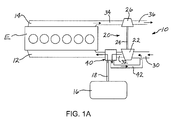
- FIG. 1A is a diagrammatic illustration of a turbocharger system in accordance with a first embodiment of the invention, with the valve system in a first condition;
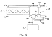
- FIG. 1B shows the system of FIG. 1A with the valve system in a second condition
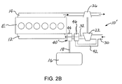
- FIG. 2A is a diagrammatic illustration of a turbocharger system in accordance with a second embodiment of the invention, with the valve system in a first condition;
- FIG. 2B shows the system of FIG. 2A with the valve system in a second condition
- FIG. 3A is a diagrammatic illustration of a turbocharger system in accordance with a third embodiment of the invention, with the valve system in a first condition;
- FIG 3B shows the system of FIG. 3A with the valve system in a second condition.
- turbocharger system now will be described more fully hereinafter with reference to the accompanying drawings in which some but not all possible embodiments are shown. Indeed, the turbocharger and actuator may be embodied in many different forms and should not be construed as limited to the embodiments set forth herein; rather, these embodiments are provided so that this disclosure will satisfy applicable legal requirements. Like numbers refer to like elements throughout.
- FIGS. 1A and 1B A turbocharger system 10 according to one embodiment of the invention is depicted in FIGS. 1A and 1B .
- the turbocharger system is shown in conjunction with an internal combustion engine E having an air intake system 12 for supplying air to the cylinders of the engine and an exhaust system 14 for conveying exhaust gases from the cylinders away from the engine.
- the vehicle of which the engine E is a part includes a pressure vessel 16 that stores pressurized air at a pressure sufficient for supercharging the engine at low engine speeds.
- the pressure vessel can be, for example, an air cylinder of an air-assisted braking system for the vehicle.
- the pressure vessel can be a dedicated pressure vessel separate from the braking system. In either case, the pressure vessel is charged by operation of a pump (not shown).
- the turbocharger system 10 includes a turbocharger 20 having a compressor 22 coupled by a shaft 24 to a turbine 26 .
- An air inlet 30 supplies fresh air into the compressor 22 .
- the compressor compresses the air and supplies it via an air conduit 32 to the air intake system 12 of the engine.
- the exhaust system 14 of the engine is connected to an exhaust conduit 34 that supplies the exhaust gas to the turbine 26 . After passing through the turbine 26 the exhaust gas is conveyed away through a further exhaust line 36 to one or more downstream devices such as exhaust gas treatment devices (not shown).
- the turbocharger system 10 further comprises a valve system 40 arranged to receive compressed air from the compressor 22 via the air conduit 32, and to separately receive pressurized air from the pressure vessel 16 via a line 18.
- the valve system 40 is electrically controllable by a suitable controller (e.g., the vehicle's ECU) to move between first and second valve conditions in which either the pressurized air from the pressure vessel 16 or the compressed air from the compressor 22 is supplied to the intake system 12 of the engine, respectively.
- the valve system shuts off the pressure vessel 16 when in the second valve condition.
- the valve system 40 is further operable, when in the first valve condition, to divert the compressed air from the compressor 22 into a recirculation conduit 42 that leads into the air inlet 30 of the compressor 22, such that compressed air from the compressor is recirculated back to the compressor inlet when the air intake system 12 is being supplied by the pressure vessel 16 .
- the valve system 40 in this embodiment comprises a single valve having two inlets and two outlets.
- the valve has a first inlet supplied by the line 18 from the pressure vessel 16 and a second inlet supplied by the conduit 32 from the compressor 22 .
- the valve has a main outlet through which air is discharged for supply to the intake system 12 of the engine, and a recirculation outlet connected to the recirculation conduit 42 .
- the valve is variably positionable. In a first position of the valve as shown in FIG. 1A , suitable for engine conditions in which the compressor 22 is unable to supply adequate quantities of sufficiently supercharged air to the engine, the first inlet for the pressure vessel 16 is connected to the main outlet, and the second inlet for the compressor 22 is connected to the recirculation conduit 42 .
- the engine's intake system 12 is supplied with pressurized air from the pressure vessel 16 and the compressed air from the compressor 22 is recirculated back to the compressor inlet to help avoid instability and/or surge of the compressor as long as the valve is in the first position
- the second inlet for the compressor 22 is connected to the main outlet and the first inlet for the pressure vessel 16 is closed off, as is the recirculation outlet.
- the engine's intake system 12 is supplied with compressed air from the compressor 22 in the usual fashion and the pressure vessel 16 is no longer involved in supercharging the engine.
- FIGS. 2A and 2B depict a turbocharger system 10' in accordance with another embodiment.
- the turbocharger system 10' is substantially similar to that of FIG. 1 , and only the significant differences are described here.
- the primary difference is that a valve system 40' is substituted for the valve system 40 of the first embodiment.
- the valve system 40' comprises two valves: a control valve 44 and a recirculation valve 46.
- the control valve 44 has a first inlet that receives pressurized air from the pressure vessel 16 via the line 18, and a second inlet that receives compressed air from the compressor 22 via the conduit 32.
- the recirculation valve 46 is disposed in the conduit 32 and has an inlet that receives compressed air from the compressor 22 .
- the recirculation valve 46 has an outlet through which the received air is fed via the conduit 32 into the second inlet of the control valve 44.
- the recirculation valve 46 also has a recirculation outlet connected to the recirculation conduit 42.
- the control valve 44 is placed in a first position in which the first inlet fed by the pressure vessel 16 is connected to the outlet of the valve such that the engine's intake system 12 is supplied with air from the pressure vessel 16 , and the recirculation valve 46 is placed in a recirculation position in which the valve's inlet is connected to the recirculation outlet such that compressed air from the compressor 22 is recirculated via the recirculation conduit 42 to the inlet 30 of the compressor, and the valve's outlet leading to the control valve 44 is closed off.
- the control valve 44 is placed in a second position in which the first inlet fed by the pressure vessel 16 is closed off and the second inlet fed by the compressor 22 is connected to the outlet of the valve such that the intake system 12 is supplied with air from the compressor 22 , and the recirculation valve 46 is placed in a non-recirculation position in which the valve's inlet is connected to the outlet that feeds the control valve 44 and the recirculation outlet is closed off.
- FIGS. 3A and 3B A third embodiment of a turbocharger system 10" is depicted in FIGS. 3A and 3B .
- This system is substantially similar to the previous embodiments and only the significant differences will be described here.
- the primary difference is that the valve system 40" is substituted for the valve systems in the prior embodiments.
- the valve system 40" comprises a recirculation valve 46" essentially the same as the recirculation valve 46 of the second embodiment, and a pressure vessel valve 48" . Whereas the control valve 44 and recirculation valve 46 of the second embodiment are arranged in series, in this third embodiment the recirculation valve 46" and pressure vessel valve 48" are effectively in parallel, each having its own connection to the intake system 12 of the engine.
- the pressure vessel valve 48" is controllable to be either open or closed (although optionally it can be openable in a variable fashion so as to control the pressure drop across the valve).
- the pressure vessel valve 48" is opened such that the engine's intake system 12 is supplied with air from the pressure vessel 16, and the recirculation valve 46" is placed in a recirculation position in which the valve's inlet is connected to the recirculation outlet such that compressed air from the compressor 22 is recirculated via the recirculation conduit 42 to the inlet 30 of the compressor, and the valve's outlet leading to the intake system 12 is closed off.
- the pressure vessel valve 48" is closed and the recirculation valve 46" is placed in a non-recirculation position in which the valve's inlet is connected to the outlet that feeds the intake system 12 and the valve's recirculation outlet is closed off, such that the intake system is fed by the compressor 22.
- the valve(s) of the valve system can be an infinitely variable type that can be regulated so as to controllably vary the pressure drop, and hence the flow rate, of the air being supplied to the engine.
- the valve(s) can be controlled in such a fashion that the pressure or flow rate of the air supplied to the engine has a desired value.
Landscapes
- Engineering & Computer Science (AREA)
- Chemical & Material Sciences (AREA)
- Combustion & Propulsion (AREA)
- Mechanical Engineering (AREA)
- General Engineering & Computer Science (AREA)
- Supercharger (AREA)
- Exhaust-Gas Circulating Devices (AREA)
Applications Claiming Priority (1)
| Application Number | Priority Date | Filing Date | Title |
|---|---|---|---|
| US12/775,166 US8434305B2 (en) | 2010-05-06 | 2010-05-06 | Compressed-air-assisted turbocharger system for internal combustion engine |
Publications (3)
| Publication Number | Publication Date |
|---|---|
| EP2385230A2 true EP2385230A2 (fr) | 2011-11-09 |
| EP2385230A3 EP2385230A3 (fr) | 2012-03-07 |
| EP2385230B1 EP2385230B1 (fr) | 2015-10-14 |
Family
ID=44314177
Family Applications (1)
| Application Number | Title | Priority Date | Filing Date |
|---|---|---|---|
| EP11164380.5A Not-in-force EP2385230B1 (fr) | 2010-05-06 | 2011-04-29 | Système de turbochargeur assisté par air comprimé pour moteur à combustion interne |
Country Status (2)
| Country | Link |
|---|---|
| US (1) | US8434305B2 (fr) |
| EP (1) | EP2385230B1 (fr) |
Cited By (10)
| Publication number | Priority date | Publication date | Assignee | Title |
|---|---|---|---|---|
| WO2014079682A1 (fr) * | 2012-11-22 | 2014-05-30 | Bayerische Motoren Werke Aktiengesellschaft | Procédé pour faire fonctionner un moteur à combustion interne à allumage extérieur comprenant un turbocompresseur à gaz d'échappement |
| WO2015011495A1 (fr) * | 2013-07-26 | 2015-01-29 | Equipmake Ltd | Économie d'énergie dans des véhicules |
| FR3011589A1 (fr) * | 2013-10-04 | 2015-04-10 | Motorisations Aeronautiques | Machine thermique aeronautique comprenant une reserve de fluide sous pression pour demarrer un moteur a cycle ferme |
| US9157446B2 (en) | 2013-01-31 | 2015-10-13 | Danfoss A/S | Centrifugal compressor with extended operating range |
| CN105308303A (zh) * | 2013-06-13 | 2016-02-03 | 戴科知识产权控股有限责任公司 | 湍振升压下气动压缩机再循环阀系统 |
| CN105370388A (zh) * | 2014-08-14 | 2016-03-02 | 福特环球技术公司 | 用于喘振控制的方法和系统 |
| RU2612542C2 (ru) * | 2011-11-10 | 2017-03-09 | ФОРД ГЛОУБАЛ ТЕКНОЛОДЖИЗ, ЭлЭлСи | Система двигателя, способ для системы турбонагнетателя и способ для двигателя с турбонаддувом с первым и вторым компрессором |
| WO2017097330A1 (fr) * | 2015-12-07 | 2017-06-15 | Volvo Truck Corporation | Système de commande et procédé de commande pour un moteur à combustion interne |
| CN110475954A (zh) * | 2017-03-17 | 2019-11-19 | 利滕斯汽车合伙公司 | 涡轮增压器系统、形成其一部分的压缩机系统及对通向发动机的空气流进行控制的方法 |
| US10962016B2 (en) | 2016-02-04 | 2021-03-30 | Danfoss A/S | Active surge control in centrifugal compressors using microjet injection |
Families Citing this family (15)
| Publication number | Priority date | Publication date | Assignee | Title |
|---|---|---|---|---|
| US8935024B2 (en) * | 2007-08-17 | 2015-01-13 | Borgwarner Inc. | Boost assist system |
| DE102009060181A1 (de) * | 2009-12-23 | 2011-06-30 | Knorr-Bremse Systeme für Nutzfahrzeuge GmbH, 80809 | Abgasturbolader für eine Verbrennungskraftmaschine mit einer Frischgasversorgungsvorrichtung und eine entsprechende Anordnung |
| US9243550B2 (en) * | 2012-03-12 | 2016-01-26 | Ford Global Technologies, Llc | Turbocharger compressor inlet flow control |
| US9382838B2 (en) * | 2012-05-17 | 2016-07-05 | Ford Global Technologies, Llc | Boost reservoir and throttle coordination |
| US10018112B2 (en) | 2013-06-05 | 2018-07-10 | Wise Motor Works, Ltd. | Internal combustion engine with paired, parallel, offset pistons |
| US9145824B2 (en) | 2013-06-13 | 2015-09-29 | Dayco Ip Holdings, Llc | Pneumatic compressor recirculation valve system for minimizing surge under boost during throttle closing |
| USD816717S1 (en) | 2014-08-18 | 2018-05-01 | Eaton Corporation | Supercharger housing |
| US9683521B2 (en) | 2013-10-31 | 2017-06-20 | Eaton Corporation | Thermal abatement systems |
| CN104847484A (zh) * | 2014-04-10 | 2015-08-19 | 北汽福田汽车股份有限公司 | 发动机负压能量利用装置及方法 |
| FR3028560B1 (fr) * | 2014-11-19 | 2016-12-23 | Peugeot Citroen Automobiles Sa | Architecture de moteur thermique suralimente munie d'un dispositif de stockage de pression |
| US9856803B2 (en) | 2015-09-11 | 2018-01-02 | Caterpillar Inc. | Natural gas engine system with improved transient response |
| US11333115B2 (en) * | 2015-11-20 | 2022-05-17 | Clark Equipment Company | Fuel recirculation method and valve |
| US10584651B2 (en) | 2016-07-25 | 2020-03-10 | Garrett Transportation I Inc. | Compressor override control |
| CN107448332B (zh) * | 2017-07-11 | 2019-10-18 | 张峻 | 一种增压无迟滞的新型汽车发动机系统 |
| CA3021866C (fr) | 2017-11-22 | 2019-09-10 | Wise Motor Works, Ltd. | Moteur a combustion interne avec pistons decales paralleles et apparies |
Family Cites Families (10)
| Publication number | Priority date | Publication date | Assignee | Title |
|---|---|---|---|---|
| US3673796A (en) | 1970-03-03 | 1972-07-04 | Caterpillar Tractor Co | Anticipating air injection system for turbocharged engines |
| US4517803A (en) | 1983-04-22 | 1985-05-21 | The Garrett Corporation | Turbocharger compressor valve |
| DE3906312C1 (fr) | 1989-02-28 | 1989-12-21 | Man Nutzfahrzeuge Ag, 8000 Muenchen, De | |
| US5819538A (en) * | 1996-11-15 | 1998-10-13 | Lawson, Jr.; Thomas Towles | Turbocharged engine system with recirculation and supplemental air supply |
| DE19944946A1 (de) * | 1999-09-20 | 2001-03-29 | Udo Reilaender | Anlage zum Ausgleich des Ladedrucks bei aufgeladenen Verbrennungsmotoren |
| DE10158874A1 (de) * | 2001-11-30 | 2003-06-12 | Daimler Chrysler Ag | Abgasturbolader für eine Brennkraftmaschine und Verfahren zum Betrieb einer aufgeladenen Brennkraftmaschine |
| DE10361913A1 (de) * | 2003-12-31 | 2005-09-08 | Birgit Bergmann | "Turboloch" (Ladeunterstützung mit Speicher) |
| MX2007010194A (es) | 2004-09-10 | 2008-11-04 | Knorr Bremse Systeme | Dispositivo para la alimentacion de aire fresco a un motor de combustion interna con embolo turbocargado y metodo para la operacion de este. |
| DE102007059145A1 (de) * | 2007-12-07 | 2009-06-10 | Deutz Ag | Dynamischer Booster |
| AT506476B1 (de) * | 2009-06-18 | 2010-12-15 | Avl List Gmbh | Brennkraftmaschine mit einem einlasssystem |
-
2010
- 2010-05-06 US US12/775,166 patent/US8434305B2/en active Active
-
2011
- 2011-04-29 EP EP11164380.5A patent/EP2385230B1/fr not_active Not-in-force
Non-Patent Citations (1)
| Title |
|---|
| None |
Cited By (18)
| Publication number | Priority date | Publication date | Assignee | Title |
|---|---|---|---|---|
| RU2612542C2 (ru) * | 2011-11-10 | 2017-03-09 | ФОРД ГЛОУБАЛ ТЕКНОЛОДЖИЗ, ЭлЭлСи | Система двигателя, способ для системы турбонагнетателя и способ для двигателя с турбонаддувом с первым и вторым компрессором |
| WO2014079682A1 (fr) * | 2012-11-22 | 2014-05-30 | Bayerische Motoren Werke Aktiengesellschaft | Procédé pour faire fonctionner un moteur à combustion interne à allumage extérieur comprenant un turbocompresseur à gaz d'échappement |
| US9689305B2 (en) | 2012-11-22 | 2017-06-27 | Bayerische Motoren Werke Aktiengesellschaft | Method for operating a spark ignition internal combustion engine with an exhaust gas turbocharger |
| CN104797810B (zh) * | 2012-11-22 | 2017-04-26 | 宝马股份公司 | 用于运行具有废气涡轮增压器的外源点火内燃机的方法 |
| US10184481B2 (en) | 2013-01-31 | 2019-01-22 | Danfoss A/S | Centrifugal compressor with extended operating range |
| US9157446B2 (en) | 2013-01-31 | 2015-10-13 | Danfoss A/S | Centrifugal compressor with extended operating range |
| CN105308303B (zh) * | 2013-06-13 | 2017-03-01 | 戴科知识产权控股有限责任公司 | 湍振升压下气动压缩机再循环阀系统 |
| CN105308303A (zh) * | 2013-06-13 | 2016-02-03 | 戴科知识产权控股有限责任公司 | 湍振升压下气动压缩机再循环阀系统 |
| WO2015011495A1 (fr) * | 2013-07-26 | 2015-01-29 | Equipmake Ltd | Économie d'énergie dans des véhicules |
| FR3011589A1 (fr) * | 2013-10-04 | 2015-04-10 | Motorisations Aeronautiques | Machine thermique aeronautique comprenant une reserve de fluide sous pression pour demarrer un moteur a cycle ferme |
| CN105370388B (zh) * | 2014-08-14 | 2019-11-19 | 福特环球技术公司 | 用于喘振控制的方法和系统 |
| CN105370388A (zh) * | 2014-08-14 | 2016-03-02 | 福特环球技术公司 | 用于喘振控制的方法和系统 |
| CN108291477A (zh) * | 2015-12-07 | 2018-07-17 | 沃尔沃卡车集团 | 用于内燃机的控制系统和控制方法 |
| WO2017097330A1 (fr) * | 2015-12-07 | 2017-06-15 | Volvo Truck Corporation | Système de commande et procédé de commande pour un moteur à combustion interne |
| US10968815B2 (en) | 2015-12-07 | 2021-04-06 | Volvo Truck Corporation | Control system and control method for an internal combustion engine |
| US10962016B2 (en) | 2016-02-04 | 2021-03-30 | Danfoss A/S | Active surge control in centrifugal compressors using microjet injection |
| CN110475954A (zh) * | 2017-03-17 | 2019-11-19 | 利滕斯汽车合伙公司 | 涡轮增压器系统、形成其一部分的压缩机系统及对通向发动机的空气流进行控制的方法 |
| CN110475954B (zh) * | 2017-03-17 | 2021-08-17 | 利滕斯汽车合伙公司 | 涡轮增压器系统、压缩机系统及控制空气流的方法 |
Also Published As
| Publication number | Publication date |
|---|---|
| EP2385230B1 (fr) | 2015-10-14 |
| US20110271672A1 (en) | 2011-11-10 |
| EP2385230A3 (fr) | 2012-03-07 |
| US8434305B2 (en) | 2013-05-07 |
Similar Documents
| Publication | Publication Date | Title |
|---|---|---|
| US8434305B2 (en) | Compressed-air-assisted turbocharger system for internal combustion engine | |
| CN106257012B (zh) | 用于内燃发动机的充气压力控制的方法 | |
| EP1327753B1 (fr) | Systeme de degasage pour un moteur à combustion interne | |
| CN106014607B (zh) | 排气涡轮增压内燃发动机及其运转方法 | |
| US6354084B1 (en) | Exhaust gas recirculation system for a turbocharged internal combustion engine | |
| US8793995B2 (en) | Systems for recovering the unused energy of exhaust gas of an internal combustion engine and corresponding methods | |
| RU2612542C2 (ru) | Система двигателя, способ для системы турбонагнетателя и способ для двигателя с турбонаддувом с первым и вторым компрессором | |
| US20100300088A1 (en) | Method of controlling a turbocharger | |
| CN103459800A (zh) | 用于增大排气歧管压力的涡轮增压器控制策略 | |
| CN107461262B (zh) | 用于发动机控制的装置和方法 | |
| US9187073B2 (en) | Negative pressure forming device for brake of vehicle | |
| US8307646B2 (en) | System using supplemental compressor for EGR | |
| US9546593B2 (en) | Method for regulating stable operation of an exhaust-gas turbocharger of an internal combustion engine, and a corresponding apparatus | |
| CN106481444A (zh) | 调节内燃发动机充气压力的方法及内燃发动机 | |
| EP2726726B1 (fr) | Moteur à combustion interne et son procédé de fonctionnement | |
| CN107975417A (zh) | 机动车辆的增压发动机系统 | |
| US20190178149A1 (en) | Energy supercharger system and method | |
| CN108368799B (zh) | 用于再生活性炭过滤器的方法 | |
| CN204851424U (zh) | 一种增压内燃机的压缩空气辅助装置 | |
| US11047294B2 (en) | Method of controlling a valve of a dual volute turbocharger | |
| US9359965B2 (en) | Turbo-charger system | |
| US10054039B2 (en) | Turbocharger system for an engine | |
| EP2912295B1 (fr) | Procédé de commande du fonctionnement d'un moteur à combustion interne, et système de commande pour commander le fonctionnement d'un moteur à combustion interne | |
| US11639703B1 (en) | System and method using secondary air pump for secondary air injection into turbocharged internal combustion engine exhaust and for transiently augmenting engine boost pressure, including means for supressing surge of the secondary air pump | |
| US20180023455A1 (en) | Multi-stage exhaust turbocharger system |
Legal Events
| Date | Code | Title | Description |
|---|---|---|---|
| 17P | Request for examination filed |
Effective date: 20110429 |
|
| AK | Designated contracting states |
Kind code of ref document: A2 Designated state(s): AL AT BE BG CH CY CZ DE DK EE ES FI FR GB GR HR HU IE IS IT LI LT LU LV MC MK MT NL NO PL PT RO RS SE SI SK SM TR |
|
| AX | Request for extension of the european patent |
Extension state: BA ME |
|
| PUAI | Public reference made under article 153(3) epc to a published international application that has entered the european phase |
Free format text: ORIGINAL CODE: 0009012 |
|
| PUAL | Search report despatched |
Free format text: ORIGINAL CODE: 0009013 |
|
| AK | Designated contracting states |
Kind code of ref document: A3 Designated state(s): AL AT BE BG CH CY CZ DE DK EE ES FI FR GB GR HR HU IE IS IT LI LT LU LV MC MK MT NL NO PL PT RO RS SE SI SK SM TR |
|
| AX | Request for extension of the european patent |
Extension state: BA ME |
|
| RIC1 | Information provided on ipc code assigned before grant |
Ipc: F02B 33/44 20060101AFI20120203BHEP Ipc: F02B 21/00 20060101ALI20120203BHEP Ipc: F02B 37/10 20060101ALI20120203BHEP Ipc: F02B 37/16 20060101ALI20120203BHEP Ipc: F02B 19/02 20060101ALI20120203BHEP |
|
| 17Q | First examination report despatched |
Effective date: 20120224 |
|
| GRAP | Despatch of communication of intention to grant a patent |
Free format text: ORIGINAL CODE: EPIDOSNIGR1 |
|
| INTG | Intention to grant announced |
Effective date: 20150602 |
|
| GRAS | Grant fee paid |
Free format text: ORIGINAL CODE: EPIDOSNIGR3 |
|
| GRAA | (expected) grant |
Free format text: ORIGINAL CODE: 0009210 |
|
| AK | Designated contracting states |
Kind code of ref document: B1 Designated state(s): AL AT BE BG CH CY CZ DE DK EE ES FI FR GB GR HR HU IE IS IT LI LT LU LV MC MK MT NL NO PL PT RO RS SE SI SK SM TR |
|
| REG | Reference to a national code |
Ref country code: GB Ref legal event code: FG4D |
|
| REG | Reference to a national code |
Ref country code: AT Ref legal event code: REF Ref document number: 755286 Country of ref document: AT Kind code of ref document: T Effective date: 20151015 Ref country code: CH Ref legal event code: EP |
|
| REG | Reference to a national code |
Ref country code: IE Ref legal event code: FG4D |
|
| REG | Reference to a national code |
Ref country code: DE Ref legal event code: R096 Ref document number: 602011020507 Country of ref document: DE |
|
| RAP2 | Party data changed (patent owner data changed or rights of a patent transferred) |
Owner name: HONEYWELL INTERNATIONAL INC. |
|
| REG | Reference to a national code |
Ref country code: NL Ref legal event code: MP Effective date: 20151014 |
|
| REG | Reference to a national code |
Ref country code: LT Ref legal event code: MG4D |
|
| REG | Reference to a national code |
Ref country code: AT Ref legal event code: MK05 Ref document number: 755286 Country of ref document: AT Kind code of ref document: T Effective date: 20151014 |
|
| REG | Reference to a national code |
Ref country code: FR Ref legal event code: PLFP Year of fee payment: 6 |
|
| PG25 | Lapsed in a contracting state [announced via postgrant information from national office to epo] |
Ref country code: NL Free format text: LAPSE BECAUSE OF FAILURE TO SUBMIT A TRANSLATION OF THE DESCRIPTION OR TO PAY THE FEE WITHIN THE PRESCRIBED TIME-LIMIT Effective date: 20151014 Ref country code: IT Free format text: LAPSE BECAUSE OF FAILURE TO SUBMIT A TRANSLATION OF THE DESCRIPTION OR TO PAY THE FEE WITHIN THE PRESCRIBED TIME-LIMIT Effective date: 20151014 Ref country code: HR Free format text: LAPSE BECAUSE OF FAILURE TO SUBMIT A TRANSLATION OF THE DESCRIPTION OR TO PAY THE FEE WITHIN THE PRESCRIBED TIME-LIMIT Effective date: 20151014 Ref country code: IS Free format text: LAPSE BECAUSE OF FAILURE TO SUBMIT A TRANSLATION OF THE DESCRIPTION OR TO PAY THE FEE WITHIN THE PRESCRIBED TIME-LIMIT Effective date: 20160214 Ref country code: ES Free format text: LAPSE BECAUSE OF FAILURE TO SUBMIT A TRANSLATION OF THE DESCRIPTION OR TO PAY THE FEE WITHIN THE PRESCRIBED TIME-LIMIT Effective date: 20151014 Ref country code: NO Free format text: LAPSE BECAUSE OF FAILURE TO SUBMIT A TRANSLATION OF THE DESCRIPTION OR TO PAY THE FEE WITHIN THE PRESCRIBED TIME-LIMIT Effective date: 20160114 Ref country code: LT Free format text: LAPSE BECAUSE OF FAILURE TO SUBMIT A TRANSLATION OF THE DESCRIPTION OR TO PAY THE FEE WITHIN THE PRESCRIBED TIME-LIMIT Effective date: 20151014 |
|
| PG25 | Lapsed in a contracting state [announced via postgrant information from national office to epo] |
Ref country code: LV Free format text: LAPSE BECAUSE OF FAILURE TO SUBMIT A TRANSLATION OF THE DESCRIPTION OR TO PAY THE FEE WITHIN THE PRESCRIBED TIME-LIMIT Effective date: 20151014 Ref country code: FI Free format text: LAPSE BECAUSE OF FAILURE TO SUBMIT A TRANSLATION OF THE DESCRIPTION OR TO PAY THE FEE WITHIN THE PRESCRIBED TIME-LIMIT Effective date: 20151014 Ref country code: GR Free format text: LAPSE BECAUSE OF FAILURE TO SUBMIT A TRANSLATION OF THE DESCRIPTION OR TO PAY THE FEE WITHIN THE PRESCRIBED TIME-LIMIT Effective date: 20160115 Ref country code: PL Free format text: LAPSE BECAUSE OF FAILURE TO SUBMIT A TRANSLATION OF THE DESCRIPTION OR TO PAY THE FEE WITHIN THE PRESCRIBED TIME-LIMIT Effective date: 20151014 Ref country code: RS Free format text: LAPSE BECAUSE OF FAILURE TO SUBMIT A TRANSLATION OF THE DESCRIPTION OR TO PAY THE FEE WITHIN THE PRESCRIBED TIME-LIMIT Effective date: 20151014 Ref country code: AT Free format text: LAPSE BECAUSE OF FAILURE TO SUBMIT A TRANSLATION OF THE DESCRIPTION OR TO PAY THE FEE WITHIN THE PRESCRIBED TIME-LIMIT Effective date: 20151014 Ref country code: PT Free format text: LAPSE BECAUSE OF FAILURE TO SUBMIT A TRANSLATION OF THE DESCRIPTION OR TO PAY THE FEE WITHIN THE PRESCRIBED TIME-LIMIT Effective date: 20160215 Ref country code: SE Free format text: LAPSE BECAUSE OF FAILURE TO SUBMIT A TRANSLATION OF THE DESCRIPTION OR TO PAY THE FEE WITHIN THE PRESCRIBED TIME-LIMIT Effective date: 20151014 |
|
| REG | Reference to a national code |
Ref country code: DE Ref legal event code: R097 Ref document number: 602011020507 Country of ref document: DE |
|
| PG25 | Lapsed in a contracting state [announced via postgrant information from national office to epo] |
Ref country code: CZ Free format text: LAPSE BECAUSE OF FAILURE TO SUBMIT A TRANSLATION OF THE DESCRIPTION OR TO PAY THE FEE WITHIN THE PRESCRIBED TIME-LIMIT Effective date: 20151014 |
|
| PLBE | No opposition filed within time limit |
Free format text: ORIGINAL CODE: 0009261 |
|
| STAA | Information on the status of an ep patent application or granted ep patent |
Free format text: STATUS: NO OPPOSITION FILED WITHIN TIME LIMIT |
|
| PG25 | Lapsed in a contracting state [announced via postgrant information from national office to epo] |
Ref country code: RO Free format text: LAPSE BECAUSE OF FAILURE TO SUBMIT A TRANSLATION OF THE DESCRIPTION OR TO PAY THE FEE WITHIN THE PRESCRIBED TIME-LIMIT Effective date: 20151014 Ref country code: SK Free format text: LAPSE BECAUSE OF FAILURE TO SUBMIT A TRANSLATION OF THE DESCRIPTION OR TO PAY THE FEE WITHIN THE PRESCRIBED TIME-LIMIT Effective date: 20151014 Ref country code: SM Free format text: LAPSE BECAUSE OF FAILURE TO SUBMIT A TRANSLATION OF THE DESCRIPTION OR TO PAY THE FEE WITHIN THE PRESCRIBED TIME-LIMIT Effective date: 20151014 Ref country code: BE Free format text: LAPSE BECAUSE OF NON-PAYMENT OF DUE FEES Effective date: 20160430 Ref country code: DK Free format text: LAPSE BECAUSE OF FAILURE TO SUBMIT A TRANSLATION OF THE DESCRIPTION OR TO PAY THE FEE WITHIN THE PRESCRIBED TIME-LIMIT Effective date: 20151014 Ref country code: EE Free format text: LAPSE BECAUSE OF FAILURE TO SUBMIT A TRANSLATION OF THE DESCRIPTION OR TO PAY THE FEE WITHIN THE PRESCRIBED TIME-LIMIT Effective date: 20151014 |
|
| 26N | No opposition filed |
Effective date: 20160715 |
|
| PG25 | Lapsed in a contracting state [announced via postgrant information from national office to epo] |
Ref country code: SI Free format text: LAPSE BECAUSE OF FAILURE TO SUBMIT A TRANSLATION OF THE DESCRIPTION OR TO PAY THE FEE WITHIN THE PRESCRIBED TIME-LIMIT Effective date: 20151014 |
|
| REG | Reference to a national code |
Ref country code: CH Ref legal event code: PL |
|
| PG25 | Lapsed in a contracting state [announced via postgrant information from national office to epo] |
Ref country code: LU Free format text: LAPSE BECAUSE OF FAILURE TO SUBMIT A TRANSLATION OF THE DESCRIPTION OR TO PAY THE FEE WITHIN THE PRESCRIBED TIME-LIMIT Effective date: 20160429 Ref country code: BE Free format text: LAPSE BECAUSE OF FAILURE TO SUBMIT A TRANSLATION OF THE DESCRIPTION OR TO PAY THE FEE WITHIN THE PRESCRIBED TIME-LIMIT Effective date: 20151014 |
|
| REG | Reference to a national code |
Ref country code: IE Ref legal event code: MM4A |
|
| PG25 | Lapsed in a contracting state [announced via postgrant information from national office to epo] |
Ref country code: LI Free format text: LAPSE BECAUSE OF NON-PAYMENT OF DUE FEES Effective date: 20160430 Ref country code: CH Free format text: LAPSE BECAUSE OF NON-PAYMENT OF DUE FEES Effective date: 20160430 |
|
| REG | Reference to a national code |
Ref country code: FR Ref legal event code: PLFP Year of fee payment: 7 |
|
| PG25 | Lapsed in a contracting state [announced via postgrant information from national office to epo] |
Ref country code: IE Free format text: LAPSE BECAUSE OF NON-PAYMENT OF DUE FEES Effective date: 20160429 |
|
| REG | Reference to a national code |
Ref country code: FR Ref legal event code: PLFP Year of fee payment: 8 |
|
| PG25 | Lapsed in a contracting state [announced via postgrant information from national office to epo] |
Ref country code: HU Free format text: LAPSE BECAUSE OF FAILURE TO SUBMIT A TRANSLATION OF THE DESCRIPTION OR TO PAY THE FEE WITHIN THE PRESCRIBED TIME-LIMIT; INVALID AB INITIO Effective date: 20110429 Ref country code: CY Free format text: LAPSE BECAUSE OF FAILURE TO SUBMIT A TRANSLATION OF THE DESCRIPTION OR TO PAY THE FEE WITHIN THE PRESCRIBED TIME-LIMIT Effective date: 20151014 |
|
| PG25 | Lapsed in a contracting state [announced via postgrant information from national office to epo] |
Ref country code: MK Free format text: LAPSE BECAUSE OF FAILURE TO SUBMIT A TRANSLATION OF THE DESCRIPTION OR TO PAY THE FEE WITHIN THE PRESCRIBED TIME-LIMIT Effective date: 20151014 Ref country code: MC Free format text: LAPSE BECAUSE OF FAILURE TO SUBMIT A TRANSLATION OF THE DESCRIPTION OR TO PAY THE FEE WITHIN THE PRESCRIBED TIME-LIMIT Effective date: 20151014 Ref country code: TR Free format text: LAPSE BECAUSE OF FAILURE TO SUBMIT A TRANSLATION OF THE DESCRIPTION OR TO PAY THE FEE WITHIN THE PRESCRIBED TIME-LIMIT Effective date: 20151014 Ref country code: MT Free format text: LAPSE BECAUSE OF NON-PAYMENT OF DUE FEES Effective date: 20160430 |
|
| PG25 | Lapsed in a contracting state [announced via postgrant information from national office to epo] |
Ref country code: BG Free format text: LAPSE BECAUSE OF FAILURE TO SUBMIT A TRANSLATION OF THE DESCRIPTION OR TO PAY THE FEE WITHIN THE PRESCRIBED TIME-LIMIT Effective date: 20151014 |
|
| PG25 | Lapsed in a contracting state [announced via postgrant information from national office to epo] |
Ref country code: AL Free format text: LAPSE BECAUSE OF FAILURE TO SUBMIT A TRANSLATION OF THE DESCRIPTION OR TO PAY THE FEE WITHIN THE PRESCRIBED TIME-LIMIT Effective date: 20151014 |
|
| REG | Reference to a national code |
Ref country code: DE Ref legal event code: R081 Ref document number: 602011020507 Country of ref document: DE Owner name: GARRETT TRANSPORTATION I INC., TORRANCE, US Free format text: FORMER OWNER: HONEYWELL INTERNATIONAL INC., MORRISTOWN, N.J., US |
|
| REG | Reference to a national code |
Ref country code: GB Ref legal event code: 732E Free format text: REGISTERED BETWEEN 20190725 AND 20190731 |
|
| PGFP | Annual fee paid to national office [announced via postgrant information from national office to epo] |
Ref country code: FR Payment date: 20190424 Year of fee payment: 9 |
|
| PG25 | Lapsed in a contracting state [announced via postgrant information from national office to epo] |
Ref country code: FR Free format text: LAPSE BECAUSE OF NON-PAYMENT OF DUE FEES Effective date: 20200430 |
|
| PGFP | Annual fee paid to national office [announced via postgrant information from national office to epo] |
Ref country code: DE Payment date: 20210428 Year of fee payment: 11 |
|
| PGFP | Annual fee paid to national office [announced via postgrant information from national office to epo] |
Ref country code: GB Payment date: 20210426 Year of fee payment: 11 |
|
| REG | Reference to a national code |
Ref country code: DE Ref legal event code: R119 Ref document number: 602011020507 Country of ref document: DE |
|
| GBPC | Gb: european patent ceased through non-payment of renewal fee |
Effective date: 20220429 |
|
| PG25 | Lapsed in a contracting state [announced via postgrant information from national office to epo] |
Ref country code: GB Free format text: LAPSE BECAUSE OF NON-PAYMENT OF DUE FEES Effective date: 20220429 Ref country code: DE Free format text: LAPSE BECAUSE OF NON-PAYMENT OF DUE FEES Effective date: 20221103 |