EP2385230A2 - Compressed-air-assisted turbocharger system for internal combustion engine - Google Patents
Compressed-air-assisted turbocharger system for internal combustion engine Download PDFInfo
- Publication number
- EP2385230A2 EP2385230A2 EP20110164380 EP11164380A EP2385230A2 EP 2385230 A2 EP2385230 A2 EP 2385230A2 EP 20110164380 EP20110164380 EP 20110164380 EP 11164380 A EP11164380 A EP 11164380A EP 2385230 A2 EP2385230 A2 EP 2385230A2
- Authority
- EP
- European Patent Office
- Prior art keywords
- valve
- compressor
- air
- pressure vessel
- engine
- Prior art date
- Legal status (The legal status is an assumption and is not a legal conclusion. Google has not performed a legal analysis and makes no representation as to the accuracy of the status listed.)
- Granted
Links
Images


Classifications
-
- F—MECHANICAL ENGINEERING; LIGHTING; HEATING; WEAPONS; BLASTING
- F02—COMBUSTION ENGINES; HOT-GAS OR COMBUSTION-PRODUCT ENGINE PLANTS
- F02B—INTERNAL-COMBUSTION PISTON ENGINES; COMBUSTION ENGINES IN GENERAL
- F02B33/00—Engines characterised by provision of pumps for charging or scavenging
- F02B33/44—Passages conducting the charge from the pump to the engine inlet, e.g. reservoirs
-
- F—MECHANICAL ENGINEERING; LIGHTING; HEATING; WEAPONS; BLASTING
- F02—COMBUSTION ENGINES; HOT-GAS OR COMBUSTION-PRODUCT ENGINE PLANTS
- F02B—INTERNAL-COMBUSTION PISTON ENGINES; COMBUSTION ENGINES IN GENERAL
- F02B21/00—Engines characterised by air-storage chambers
-
- F—MECHANICAL ENGINEERING; LIGHTING; HEATING; WEAPONS; BLASTING
- F02—COMBUSTION ENGINES; HOT-GAS OR COMBUSTION-PRODUCT ENGINE PLANTS
- F02B—INTERNAL-COMBUSTION PISTON ENGINES; COMBUSTION ENGINES IN GENERAL
- F02B37/00—Engines characterised by provision of pumps driven at least for part of the time by exhaust
- F02B37/04—Engines with exhaust drive and other drive of pumps, e.g. with exhaust-driven pump and mechanically-driven second pump
- F02B37/10—Engines with exhaust drive and other drive of pumps, e.g. with exhaust-driven pump and mechanically-driven second pump at least one pump being alternatively or simultaneously driven by exhaust and other drive, e.g. by pressurised fluid from a reservoir or an engine-driven pump
-
- F—MECHANICAL ENGINEERING; LIGHTING; HEATING; WEAPONS; BLASTING
- F02—COMBUSTION ENGINES; HOT-GAS OR COMBUSTION-PRODUCT ENGINE PLANTS
- F02B—INTERNAL-COMBUSTION PISTON ENGINES; COMBUSTION ENGINES IN GENERAL
- F02B37/00—Engines characterised by provision of pumps driven at least for part of the time by exhaust
- F02B37/12—Control of the pumps
- F02B37/16—Control of the pumps by bypassing charging air
-
- Y—GENERAL TAGGING OF NEW TECHNOLOGICAL DEVELOPMENTS; GENERAL TAGGING OF CROSS-SECTIONAL TECHNOLOGIES SPANNING OVER SEVERAL SECTIONS OF THE IPC; TECHNICAL SUBJECTS COVERED BY FORMER USPC CROSS-REFERENCE ART COLLECTIONS [XRACs] AND DIGESTS
- Y02—TECHNOLOGIES OR APPLICATIONS FOR MITIGATION OR ADAPTATION AGAINST CLIMATE CHANGE
- Y02T—CLIMATE CHANGE MITIGATION TECHNOLOGIES RELATED TO TRANSPORTATION
- Y02T10/00—Road transport of goods or passengers
- Y02T10/10—Internal combustion engine [ICE] based vehicles
- Y02T10/12—Improving ICE efficiencies
-
- Y—GENERAL TAGGING OF NEW TECHNOLOGICAL DEVELOPMENTS; GENERAL TAGGING OF CROSS-SECTIONAL TECHNOLOGIES SPANNING OVER SEVERAL SECTIONS OF THE IPC; TECHNICAL SUBJECTS COVERED BY FORMER USPC CROSS-REFERENCE ART COLLECTIONS [XRACs] AND DIGESTS
- Y10—TECHNICAL SUBJECTS COVERED BY FORMER USPC
- Y10T—TECHNICAL SUBJECTS COVERED BY FORMER US CLASSIFICATION
- Y10T137/00—Fluid handling
- Y10T137/8593—Systems
- Y10T137/85978—With pump
- Y10T137/86035—Combined with fluid receiver
- Y10T137/86051—Compressed air supply unit
Definitions
- the present disclosure relates to exhaust gas-driven turbochargers for internal combustion engines.
- the transient response of internal combustion engines in passenger vehicles and trucks is a critical parameter in terms of overall driveability and efficiency of the engine system.
- an exhaust gas-driven turbocharger When the engine is boosted by an exhaust gas-driven turbocharger, it is often difficult to provide sufficient air to the engine at low engine speeds so as to rapidly accelerate the engine and vehicle. This is due in part to the low exhaust gas energy and hence low turbine power extraction at low engine speed.
- a drawback of this approach is that when the valve is positioned to shut off the compressor air flow to the engine, the compressor can become unstable and possibly go into a surge condition, which can create unwanted vibration and noise and/or can damage the turbocharger bearing system.
- the present disclosure relates to a turbocharger system for an internal combustion engine that powers a vehicle having a pressure vessel storing pressurized air.
- the turbocharger system comprises a turbocharger and a valve system.
- the system is configured such that the air intake system of the internal combustion engine can be supplied with air at super-atmospheric pressure either from the compressor of the turbocharger or from the pressure vessel.
- compressed air from the compressor is recirculated back to the air inlet of the compressor so as to help prevent a surge condition in the compressor.
- the valve system is arranged to receive compressed air from the compressor and to separately receive pressurized air from the pressure vessel.
- the valve system is electrically controllable to move between first and second valve conditions in which either the pressurized air from the pressure vessel or the compressed air from the compressor is supplied to the intake system of the engine, respectively, the valve system shutting off the pressure vessel when in the second valve condition.
- the valve system is further operable, when in the first valve condition, to divert the compressed air from the compressor into a recirculation conduit that leads into the air inlet of the compressor, such that compressed air is recirculated back to the compressor when the air intake system is being supplied by the pressure vessel.
- An electronic controller e.g., the vehicle ECU
- the valve system can be of various configurations.
- the valve system comprises a single valve defining a first inlet receiving the pressurized air from the pressure vessel, a second inlet receiving the compressed air from the compressor, a main outlet through which air is discharged for supply to the intake system of the engine, and a recirculation outlet through which compressed air received at the second inlet is recirculated through the recirculation conduit back to the compressor.
- the valve In the first valve condition, the valve is configured to connect the first inlet to the main outlet and to connect the second inlet to the recirculation outlet.
- the valve is configured to connect the second inlet to the main outlet and to close off the flow of pressurized air received at the first inlet.
- the valve system comprises a control valve and a separate recirculation valve.
- the control valve defines a first inlet receiving the pressurized air from the pressure vessel, a second inlet receiving the compressed air from the compressor, and an outlet through which air is discharged for supply to the intake system of the engine.
- the recirculation valve defines an inlet receiving the compressed air from the compressor, an outlet through which the compressed air received at the inlet is discharged for supply to the second inlet of the control valve, and a recirculation outlet through which compressed air received at the inlet is recirculated through the recirculation conduit back to the compressor.
- the first valve condition of the valve system is characterized by the recirculation valve being positioned to recirculate the compressed air from the compressor through the recirculation conduit back to the compressor and the control valve being positioned to supply the pressurized air from the pressure vessel to the intake system of the engine.
- the second valve condition of the valve system is characterized by the recirculation valve being positioned to pass the compressed air from the compressor on to the second inlet of the control valve and the control valve being positioned to supply the compressed air through the outlet of the control valve to the intake system of the engine.
- the valve system comprises a pressure vessel valve and a separate recirculation valve.
- the pressure vessel valve is arranged to receive pressurized air from the pressure vessel, to supply the pressurized air to the intake system when the pressure vessel valve is in an open condition, and to prevent supply of the pressurized air to the intake system when the pressure vessel valve is in a closed condition.
- the recirculation valve is arranged to receive compressed air from the compressor, to supply the compressed air to the intake system when the recirculation valve is in a non-recirculation condition, and to recirculate the compressed air through the recirculation conduit back to the compressor when the recirculation valve is in a recirculation condition.
- the first valve condition of the valve system is characterized by the recirculation valve being in the recirculation condition and the pressure vessel valve being in the open condition
- the second valve condition of the valve system is characterized by the recirculation valve being in the non-recirculation condition and the pressure vessel valve being in the closed condition.
- valve system functions to recirculate compressed air from the compressor back to the air inlet of the compressor when the pressure vessel is supplying the engine intake system.
- a method for operating a turbocharger system for an internal combustion engine comprises the steps of (1) providing a turbocharger including a compressor driven by a turbine, the turbine defining an exhaust gas inlet for receiving exhaust gas from the engine and an exhaust gas outlet through which exhaust gas is discharged, the compressor defining an air inlet for receiving air to be compressed and an air outlet through which compressed air is discharged for delivery to an intake system of the engine; (2) providing a pressure vessel containing pressurized air; (3) selectively supplying an intake system of the engine with air either from the compressor or from the pressure vessel, dependent on at least one performance parameter of the engine; and (4) when the pressure vessel is supplying the air to the intake system, recirculating compressed air from the air outlet of the compressor back to the air inlet of the compressor.
- the at least one performance parameter of the engine includes engine speed.
- the intake system can be supplied by the pressure vessel when engine speed is below a predetermined value, and the intake system can be supplied by the compressor when engine speed is above the predetermined value.
- This is a simple scheme for deciding whether the pressure vessel or the compressor is to supply the air to the engine. More-complex schemes of course can be employed, if desired. For instance, both engine speed and another parameter (e.g., engine throttle setting) can be factored into the decision.
- the pressure vessel may supply the engine only when engine speed is below a predetermined value and engine throttle setting is above a predetermined level, and otherwise the compressor supplies the engine. [Feel free to alter this description—these are just my musings.]
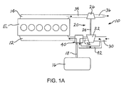
- FIG. 1A is a diagrammatic illustration of a turbocharger system in accordance with a first embodiment of the invention, with the valve system in a first condition;
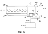
- FIG. 1B shows the system of FIG. 1A with the valve system in a second condition
- FIG. 2A is a diagrammatic illustration of a turbocharger system in accordance with a second embodiment of the invention, with the valve system in a first condition;
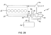
- FIG. 2B shows the system of FIG. 2A with the valve system in a second condition
- FIG. 3A is a diagrammatic illustration of a turbocharger system in accordance with a third embodiment of the invention, with the valve system in a first condition;
- FIG 3B shows the system of FIG. 3A with the valve system in a second condition.
- turbocharger system now will be described more fully hereinafter with reference to the accompanying drawings in which some but not all possible embodiments are shown. Indeed, the turbocharger and actuator may be embodied in many different forms and should not be construed as limited to the embodiments set forth herein; rather, these embodiments are provided so that this disclosure will satisfy applicable legal requirements. Like numbers refer to like elements throughout.
- FIGS. 1A and 1B A turbocharger system 10 according to one embodiment of the invention is depicted in FIGS. 1A and 1B .
- the turbocharger system is shown in conjunction with an internal combustion engine E having an air intake system 12 for supplying air to the cylinders of the engine and an exhaust system 14 for conveying exhaust gases from the cylinders away from the engine.
- the vehicle of which the engine E is a part includes a pressure vessel 16 that stores pressurized air at a pressure sufficient for supercharging the engine at low engine speeds.
- the pressure vessel can be, for example, an air cylinder of an air-assisted braking system for the vehicle.
- the pressure vessel can be a dedicated pressure vessel separate from the braking system. In either case, the pressure vessel is charged by operation of a pump (not shown).
- the turbocharger system 10 includes a turbocharger 20 having a compressor 22 coupled by a shaft 24 to a turbine 26 .
- An air inlet 30 supplies fresh air into the compressor 22 .
- the compressor compresses the air and supplies it via an air conduit 32 to the air intake system 12 of the engine.
- the exhaust system 14 of the engine is connected to an exhaust conduit 34 that supplies the exhaust gas to the turbine 26 . After passing through the turbine 26 the exhaust gas is conveyed away through a further exhaust line 36 to one or more downstream devices such as exhaust gas treatment devices (not shown).
- the turbocharger system 10 further comprises a valve system 40 arranged to receive compressed air from the compressor 22 via the air conduit 32, and to separately receive pressurized air from the pressure vessel 16 via a line 18.
- the valve system 40 is electrically controllable by a suitable controller (e.g., the vehicle's ECU) to move between first and second valve conditions in which either the pressurized air from the pressure vessel 16 or the compressed air from the compressor 22 is supplied to the intake system 12 of the engine, respectively.
- the valve system shuts off the pressure vessel 16 when in the second valve condition.
- the valve system 40 is further operable, when in the first valve condition, to divert the compressed air from the compressor 22 into a recirculation conduit 42 that leads into the air inlet 30 of the compressor 22, such that compressed air from the compressor is recirculated back to the compressor inlet when the air intake system 12 is being supplied by the pressure vessel 16 .
- the valve system 40 in this embodiment comprises a single valve having two inlets and two outlets.
- the valve has a first inlet supplied by the line 18 from the pressure vessel 16 and a second inlet supplied by the conduit 32 from the compressor 22 .
- the valve has a main outlet through which air is discharged for supply to the intake system 12 of the engine, and a recirculation outlet connected to the recirculation conduit 42 .
- the valve is variably positionable. In a first position of the valve as shown in FIG. 1A , suitable for engine conditions in which the compressor 22 is unable to supply adequate quantities of sufficiently supercharged air to the engine, the first inlet for the pressure vessel 16 is connected to the main outlet, and the second inlet for the compressor 22 is connected to the recirculation conduit 42 .
- the engine's intake system 12 is supplied with pressurized air from the pressure vessel 16 and the compressed air from the compressor 22 is recirculated back to the compressor inlet to help avoid instability and/or surge of the compressor as long as the valve is in the first position
- the second inlet for the compressor 22 is connected to the main outlet and the first inlet for the pressure vessel 16 is closed off, as is the recirculation outlet.
- the engine's intake system 12 is supplied with compressed air from the compressor 22 in the usual fashion and the pressure vessel 16 is no longer involved in supercharging the engine.
- FIGS. 2A and 2B depict a turbocharger system 10' in accordance with another embodiment.
- the turbocharger system 10' is substantially similar to that of FIG. 1 , and only the significant differences are described here.
- the primary difference is that a valve system 40' is substituted for the valve system 40 of the first embodiment.
- the valve system 40' comprises two valves: a control valve 44 and a recirculation valve 46.
- the control valve 44 has a first inlet that receives pressurized air from the pressure vessel 16 via the line 18, and a second inlet that receives compressed air from the compressor 22 via the conduit 32.
- the recirculation valve 46 is disposed in the conduit 32 and has an inlet that receives compressed air from the compressor 22 .
- the recirculation valve 46 has an outlet through which the received air is fed via the conduit 32 into the second inlet of the control valve 44.
- the recirculation valve 46 also has a recirculation outlet connected to the recirculation conduit 42.
- the control valve 44 is placed in a first position in which the first inlet fed by the pressure vessel 16 is connected to the outlet of the valve such that the engine's intake system 12 is supplied with air from the pressure vessel 16 , and the recirculation valve 46 is placed in a recirculation position in which the valve's inlet is connected to the recirculation outlet such that compressed air from the compressor 22 is recirculated via the recirculation conduit 42 to the inlet 30 of the compressor, and the valve's outlet leading to the control valve 44 is closed off.
- the control valve 44 is placed in a second position in which the first inlet fed by the pressure vessel 16 is closed off and the second inlet fed by the compressor 22 is connected to the outlet of the valve such that the intake system 12 is supplied with air from the compressor 22 , and the recirculation valve 46 is placed in a non-recirculation position in which the valve's inlet is connected to the outlet that feeds the control valve 44 and the recirculation outlet is closed off.
- FIGS. 3A and 3B A third embodiment of a turbocharger system 10" is depicted in FIGS. 3A and 3B .
- This system is substantially similar to the previous embodiments and only the significant differences will be described here.
- the primary difference is that the valve system 40" is substituted for the valve systems in the prior embodiments.
- the valve system 40" comprises a recirculation valve 46" essentially the same as the recirculation valve 46 of the second embodiment, and a pressure vessel valve 48" . Whereas the control valve 44 and recirculation valve 46 of the second embodiment are arranged in series, in this third embodiment the recirculation valve 46" and pressure vessel valve 48" are effectively in parallel, each having its own connection to the intake system 12 of the engine.
- the pressure vessel valve 48" is controllable to be either open or closed (although optionally it can be openable in a variable fashion so as to control the pressure drop across the valve).
- the pressure vessel valve 48" is opened such that the engine's intake system 12 is supplied with air from the pressure vessel 16, and the recirculation valve 46" is placed in a recirculation position in which the valve's inlet is connected to the recirculation outlet such that compressed air from the compressor 22 is recirculated via the recirculation conduit 42 to the inlet 30 of the compressor, and the valve's outlet leading to the intake system 12 is closed off.
- the pressure vessel valve 48" is closed and the recirculation valve 46" is placed in a non-recirculation position in which the valve's inlet is connected to the outlet that feeds the intake system 12 and the valve's recirculation outlet is closed off, such that the intake system is fed by the compressor 22.
- the valve(s) of the valve system can be an infinitely variable type that can be regulated so as to controllably vary the pressure drop, and hence the flow rate, of the air being supplied to the engine.
- the valve(s) can be controlled in such a fashion that the pressure or flow rate of the air supplied to the engine has a desired value.
Landscapes
- Engineering & Computer Science (AREA)
- Chemical & Material Sciences (AREA)
- Combustion & Propulsion (AREA)
- Mechanical Engineering (AREA)
- General Engineering & Computer Science (AREA)
- Supercharger (AREA)
- Exhaust-Gas Circulating Devices (AREA)
Abstract
Description
- The present disclosure relates to exhaust gas-driven turbochargers for internal combustion engines.
- The transient response of internal combustion engines in passenger vehicles and trucks is a critical parameter in terms of overall driveability and efficiency of the engine system. When the engine is boosted by an exhaust gas-driven turbocharger, it is often difficult to provide sufficient air to the engine at low engine speeds so as to rapidly accelerate the engine and vehicle. This is due in part to the low exhaust gas energy and hence low turbine power extraction at low engine speed.
- One approach that has been proposed for alleviating this poor responsiveness at low engine speeds, specifically for medium- and heavy-duty trucks, is to use pressurized air from the air cylinders of the truck's air-assisted brake system (or from a separate pressure vessel charged by the air-assisted brake system) to supply air to the engine intake system at low engine speeds. Such proposals typically employ a three-way valve having two inlets and one outlet. One inlet is connected to the compressor and the other inlet is connected to the air cylinder. The valve can be operated to supply either the compressor discharge air or the pressurized air from the air cylinder through the valve outlet to the engine intake.
- A drawback of this approach is that when the valve is positioned to shut off the compressor air flow to the engine, the compressor can become unstable and possibly go into a surge condition, which can create unwanted vibration and noise and/or can damage the turbocharger bearing system.
- The present disclosure relates to a turbocharger system for an internal combustion engine that powers a vehicle having a pressure vessel storing pressurized air. The turbocharger system comprises a turbocharger and a valve system. The system is configured such that the air intake system of the internal combustion engine can be supplied with air at super-atmospheric pressure either from the compressor of the turbocharger or from the pressure vessel. When the pressure vessel is supplying the intake system, compressed air from the compressor is recirculated back to the air inlet of the compressor so as to help prevent a surge condition in the compressor.
- In accordance with one embodiment described herein, the valve system is arranged to receive compressed air from the compressor and to separately receive pressurized air from the pressure vessel. The valve system is electrically controllable to move between first and second valve conditions in which either the pressurized air from the pressure vessel or the compressed air from the compressor is supplied to the intake system of the engine, respectively, the valve system shutting off the pressure vessel when in the second valve condition. The valve system is further operable, when in the first valve condition, to divert the compressed air from the compressor into a recirculation conduit that leads into the air inlet of the compressor, such that compressed air is recirculated back to the compressor when the air intake system is being supplied by the pressure vessel. An electronic controller (e.g., the vehicle ECU) can be programmed to control the valve system to move it between the first and second conditions as a function of one or more measured engine performance parameters.
- The valve system can be of various configurations. For example, in one embodiment the valve system comprises a single valve defining a first inlet receiving the pressurized air from the pressure vessel, a second inlet receiving the compressed air from the compressor, a main outlet through which air is discharged for supply to the intake system of the engine, and a recirculation outlet through which compressed air received at the second inlet is recirculated through the recirculation conduit back to the compressor. In the first valve condition, the valve is configured to connect the first inlet to the main outlet and to connect the second inlet to the recirculation outlet. In the second valve condition, the valve is configured to connect the second inlet to the main outlet and to close off the flow of pressurized air received at the first inlet.
- In another embodiment, the valve system comprises a control valve and a separate recirculation valve. The control valve defines a first inlet receiving the pressurized air from the pressure vessel, a second inlet receiving the compressed air from the compressor, and an outlet through which air is discharged for supply to the intake system of the engine. The recirculation valve defines an inlet receiving the compressed air from the compressor, an outlet through which the compressed air received at the inlet is discharged for supply to the second inlet of the control valve, and a recirculation outlet through which compressed air received at the inlet is recirculated through the recirculation conduit back to the compressor. Thus, the first valve condition of the valve system is characterized by the recirculation valve being positioned to recirculate the compressed air from the compressor through the recirculation conduit back to the compressor and the control valve being positioned to supply the pressurized air from the pressure vessel to the intake system of the engine. The second valve condition of the valve system is characterized by the recirculation valve being positioned to pass the compressed air from the compressor on to the second inlet of the control valve and the control valve being positioned to supply the compressed air through the outlet of the control valve to the intake system of the engine.
- In yet another embodiment, the valve system comprises a pressure vessel valve and a separate recirculation valve. The pressure vessel valve is arranged to receive pressurized air from the pressure vessel, to supply the pressurized air to the intake system when the pressure vessel valve is in an open condition, and to prevent supply of the pressurized air to the intake system when the pressure vessel valve is in a closed condition. The recirculation valve is arranged to receive compressed air from the compressor, to supply the compressed air to the intake system when the recirculation valve is in a non-recirculation condition, and to recirculate the compressed air through the recirculation conduit back to the compressor when the recirculation valve is in a recirculation condition. Thus, the first valve condition of the valve system is characterized by the recirculation valve being in the recirculation condition and the pressure vessel valve being in the open condition, and the second valve condition of the valve system is characterized by the recirculation valve being in the non-recirculation condition and the pressure vessel valve being in the closed condition.
- It is thus apparent that the particular details of the valve system are not critical, as long as the valve system functions to recirculate compressed air from the compressor back to the air inlet of the compressor when the pressure vessel is supplying the engine intake system.
- The present disclosure also describes methods for operating a turbocharger system for an internal combustion engine. In one embodiment, a method for operating a turbocharger system for an internal combustion engine comprises the steps of (1) providing a turbocharger including a compressor driven by a turbine, the turbine defining an exhaust gas inlet for receiving exhaust gas from the engine and an exhaust gas outlet through which exhaust gas is discharged, the compressor defining an air inlet for receiving air to be compressed and an air outlet through which compressed air is discharged for delivery to an intake system of the engine; (2) providing a pressure vessel containing pressurized air; (3) selectively supplying an intake system of the engine with air either from the compressor or from the pressure vessel, dependent on at least one performance parameter of the engine; and (4) when the pressure vessel is supplying the air to the intake system, recirculating compressed air from the air outlet of the compressor back to the air inlet of the compressor.
- In one embodiment, the at least one performance parameter of the engine includes engine speed. For example, the intake system can be supplied by the pressure vessel when engine speed is below a predetermined value, and the intake system can be supplied by the compressor when engine speed is above the predetermined value. This is a simple scheme for deciding whether the pressure vessel or the compressor is to supply the air to the engine. More-complex schemes of course can be employed, if desired. For instance, both engine speed and another parameter (e.g., engine throttle setting) can be factored into the decision. Thus, the pressure vessel may supply the engine only when engine speed is below a predetermined value and engine throttle setting is above a predetermined level, and otherwise the compressor supplies the engine. [Feel free to alter this description—these are just my musings.]
- Having thus described the disclosure in general terms, reference will now be made to the accompanying drawings, which are not necessarily drawn to scale, and wherein:
-
FIG. 1A is a diagrammatic illustration of a turbocharger system in accordance with a first embodiment of the invention, with the valve system in a first condition; -
FIG. 1B shows the system ofFIG. 1A with the valve system in a second condition; -
FIG. 2A is a diagrammatic illustration of a turbocharger system in accordance with a second embodiment of the invention, with the valve system in a first condition; -
FIG. 2B shows the system ofFIG. 2A with the valve system in a second condition; -
FIG. 3A is a diagrammatic illustration of a turbocharger system in accordance with a third embodiment of the invention, with the valve system in a first condition; and -
FIG 3B shows the system ofFIG. 3A with the valve system in a second condition. - The turbocharger system now will be described more fully hereinafter with reference to the accompanying drawings in which some but not all possible embodiments are shown. Indeed, the turbocharger and actuator may be embodied in many different forms and should not be construed as limited to the embodiments set forth herein; rather, these embodiments are provided so that this disclosure will satisfy applicable legal requirements. Like numbers refer to like elements throughout.
- A
turbocharger system 10 according to one embodiment of the invention is depicted inFIGS. 1A and1B . The turbocharger system is shown in conjunction with an internal combustion engine E having anair intake system 12 for supplying air to the cylinders of the engine and anexhaust system 14 for conveying exhaust gases from the cylinders away from the engine. The vehicle of which the engine E is a part includes apressure vessel 16 that stores pressurized air at a pressure sufficient for supercharging the engine at low engine speeds. The pressure vessel can be, for example, an air cylinder of an air-assisted braking system for the vehicle. Alternatively the pressure vessel can be a dedicated pressure vessel separate from the braking system. In either case, the pressure vessel is charged by operation of a pump (not shown). - The
turbocharger system 10 includes aturbocharger 20 having acompressor 22 coupled by ashaft 24 to aturbine 26. Anair inlet 30 supplies fresh air into thecompressor 22. The compressor compresses the air and supplies it via anair conduit 32 to theair intake system 12 of the engine. Theexhaust system 14 of the engine is connected to anexhaust conduit 34 that supplies the exhaust gas to theturbine 26. After passing through theturbine 26 the exhaust gas is conveyed away through afurther exhaust line 36 to one or more downstream devices such as exhaust gas treatment devices (not shown). - The
turbocharger system 10 further comprises avalve system 40 arranged to receive compressed air from thecompressor 22 via theair conduit 32, and to separately receive pressurized air from thepressure vessel 16 via aline 18. Thevalve system 40 is electrically controllable by a suitable controller (e.g., the vehicle's ECU) to move between first and second valve conditions in which either the pressurized air from thepressure vessel 16 or the compressed air from thecompressor 22 is supplied to theintake system 12 of the engine, respectively. The valve system shuts off thepressure vessel 16 when in the second valve condition. - The
valve system 40 is further operable, when in the first valve condition, to divert the compressed air from thecompressor 22 into arecirculation conduit 42 that leads into theair inlet 30 of thecompressor 22, such that compressed air from the compressor is recirculated back to the compressor inlet when theair intake system 12 is being supplied by thepressure vessel 16. - The
valve system 40 in this embodiment comprises a single valve having two inlets and two outlets. Specifically, the valve has a first inlet supplied by theline 18 from thepressure vessel 16 and a second inlet supplied by theconduit 32 from thecompressor 22. The valve has a main outlet through which air is discharged for supply to theintake system 12 of the engine, and a recirculation outlet connected to therecirculation conduit 42. The valve is variably positionable. In a first position of the valve as shown inFIG. 1A , suitable for engine conditions in which thecompressor 22 is unable to supply adequate quantities of sufficiently supercharged air to the engine, the first inlet for thepressure vessel 16 is connected to the main outlet, and the second inlet for thecompressor 22 is connected to therecirculation conduit 42. Thus, the engine'sintake system 12 is supplied with pressurized air from thepressure vessel 16 and the compressed air from thecompressor 22 is recirculated back to the compressor inlet to help avoid instability and/or surge of the compressor as long as the valve is in the first position. - In a second position of the valve as shown in
FIG. 1B , suitable for engine conditions in which thecompressor 22 is able to properly supply the engine with air, the second inlet for thecompressor 22 is connected to the main outlet and the first inlet for thepressure vessel 16 is closed off, as is the recirculation outlet. Thus, the engine'sintake system 12 is supplied with compressed air from thecompressor 22 in the usual fashion and thepressure vessel 16 is no longer involved in supercharging the engine. -
FIGS. 2A and2B depict a turbocharger system 10' in accordance with another embodiment. The turbocharger system 10' is substantially similar to that ofFIG. 1 , and only the significant differences are described here. The primary difference is that a valve system 40' is substituted for thevalve system 40 of the first embodiment. The valve system 40' comprises two valves: acontrol valve 44 and arecirculation valve 46. Thecontrol valve 44 has a first inlet that receives pressurized air from thepressure vessel 16 via theline 18, and a second inlet that receives compressed air from thecompressor 22 via theconduit 32. Therecirculation valve 46 is disposed in theconduit 32 and has an inlet that receives compressed air from thecompressor 22. Therecirculation valve 46 has an outlet through which the received air is fed via theconduit 32 into the second inlet of thecontrol valve 44. Therecirculation valve 46 also has a recirculation outlet connected to therecirculation conduit 42. - As shown in
FIG. 2A , at engine conditions in which thecompressor 22 is unable to supply adequate quantities of sufficiently supercharged air to the engine, thecontrol valve 44 is placed in a first position in which the first inlet fed by thepressure vessel 16 is connected to the outlet of the valve such that the engine'sintake system 12 is supplied with air from thepressure vessel 16, and therecirculation valve 46 is placed in a recirculation position in which the valve's inlet is connected to the recirculation outlet such that compressed air from thecompressor 22 is recirculated via therecirculation conduit 42 to theinlet 30 of the compressor, and the valve's outlet leading to thecontrol valve 44 is closed off. - As shown in
FIG. 2B , at engine conditions in which thecompressor 22 is able to properly supercharge the engine, thecontrol valve 44 is placed in a second position in which the first inlet fed by thepressure vessel 16 is closed off and the second inlet fed by thecompressor 22 is connected to the outlet of the valve such that theintake system 12 is supplied with air from thecompressor 22, and therecirculation valve 46 is placed in a non-recirculation position in which the valve's inlet is connected to the outlet that feeds thecontrol valve 44 and the recirculation outlet is closed off. - A third embodiment of a
turbocharger system 10" is depicted inFIGS. 3A and3B . This system is substantially similar to the previous embodiments and only the significant differences will be described here. The primary difference is that thevalve system 40" is substituted for the valve systems in the prior embodiments. Thevalve system 40" comprises arecirculation valve 46" essentially the same as therecirculation valve 46 of the second embodiment, and apressure vessel valve 48". Whereas thecontrol valve 44 andrecirculation valve 46 of the second embodiment are arranged in series, in this third embodiment therecirculation valve 46" andpressure vessel valve 48" are effectively in parallel, each having its own connection to theintake system 12 of the engine. Thepressure vessel valve 48" is controllable to be either open or closed (although optionally it can be openable in a variable fashion so as to control the pressure drop across the valve). - As shown in
FIG. 3A , at engine conditions in which thecompressor 22 is unable to supply adequate quantities of sufficiently supercharged air to the engine, thepressure vessel valve 48" is opened such that the engine'sintake system 12 is supplied with air from thepressure vessel 16, and therecirculation valve 46" is placed in a recirculation position in which the valve's inlet is connected to the recirculation outlet such that compressed air from thecompressor 22 is recirculated via therecirculation conduit 42 to theinlet 30 of the compressor, and the valve's outlet leading to theintake system 12 is closed off. - As shown in
FIG. 3B , at engine conditions in which thecompressor 22 is able to properly supercharge the engine, thepressure vessel valve 48" is closed and therecirculation valve 46" is placed in a non-recirculation position in which the valve's inlet is connected to the outlet that feeds theintake system 12 and the valve's recirculation outlet is closed off, such that the intake system is fed by thecompressor 22. - In any of the embodiments described above or other variations of the turbocharger system, the valve(s) of the valve system can be an infinitely variable type that can be regulated so as to controllably vary the pressure drop, and hence the flow rate, of the air being supplied to the engine. The valve(s) can be controlled in such a fashion that the pressure or flow rate of the air supplied to the engine has a desired value.
- Many modifications and other embodiments of the inventions set forth herein will come to mind to one skilled in the art to which these inventions pertain having the benefit of the teachings presented in the foregoing descriptions and the associated drawings. Therefore, it is to be understood that the inventions are not to be limited to the specific embodiments disclosed and that modifications and other embodiments are intended to be included within the scope of the appended claims. Although specific terms are employed herein, they are used in a generic and descriptive sense only and not for purposes of limitation.
Claims (8)
- A turbocharger system for an internal combustion engine that powers a vehicle having a pressure vessel storing pressurized air, the turbocharger system comprising:a turbocharger including a compressor driven by a turbine, the turbine defining an exhaust gas inlet for receiving exhaust gas from the engine and an exhaust gas outlet through which exhaust gas is discharged, the compressor defining an air inlet for receiving air to be compressed and an air outlet through which compressed air is discharged for delivery to an intake system of the engine;a valve system arranged to receive compressed air from the compressor and to separately receive pressurized air from the pressure vessel, the valve system being electrically controllable to move between first and second valve conditions in which either the pressurized air from the pressure vessel or the compressed air from the compressor is supplied to the intake system of the engine, respectively, the valve system shutting off the pressure vessel when in the second valve condition;wherein the valve system is further operable, when in the first valve condition, to divert the compressed air from the compressor into a recirculation conduit that leads into the air inlet of the compressor, such that compressed air is recirculated back to the compressor when the air intake system is being supplied by the pressure vessel.
- The turbocharger system of claim 1, wherein the valve system comprises a single valve defining a first inlet receiving the pressurized air from the pressure vessel, a second inlet receiving the compressed air from the compressor, a main outlet through which air is discharged for supply to the intake system of the engine, and a recirculation outlet through which compressed air received at the second inlet is recirculated through the recirculation conduit back to the compressor.
- The turbocharger system of claim 1, wherein the valve system comprises a control valve and a separate recirculation valve, the control valve defining a first inlet receiving the pressurized air from the pressure vessel, a second inlet receiving the compressed air from the compressor, and an outlet through which air is discharged for supply to the intake system of the engine, the recirculation valve defining an inlet receiving the compressed air from the compressor, an outlet through which the compressed air received at the inlet is discharged for supply to the second inlet of the control valve, and a recirculation outlet through which compressed air received at the inlet is recirculated through the recirculation conduit back to the compressor, wherein the first valve condition of the valve system is characterized by the recirculation valve being positioned to recirculate the compressed air from the compressor through the recirculation conduit back to the compressor and the control valve being positioned to supply the pressurized air from the pressure vessel to the intake system of the engine, and the second valve condition of the valve system is characterized by the recirculation valve being positioned to pass the compressed air from the compressor on to the second inlet of the control valve and the control valve being positioned to supply the compressed air through the outlet of the control valve to the intake system of the engine.
- The turbocharger system of claim 1, wherein the valve system comprises a pressure vessel valve and a separate recirculation valve, the pressure vessel valve being arranged to receive pressurized air from the pressure vessel, to supply the pressurized air to the intake system when the pressure vessel valve is in an open condition, and to prevent supply of the pressurized air to the intake system when the pressure vessel valve is in a closed condition, the recirculation valve being arranged to receive compressed air from the compressor, to supply the compressed air to the intake system when the recirculation valve is in a non-recirculation condition, and to recirculate the compressed air through the recirculation conduit back to the compressor when the recirculation valve is in a recirculation condition, wherein the first valve condition of the valve system is characterized by the recirculation valve being in the recirculation condition and the pressure vessel valve being in the open condition, and the second valve condition of the valve system is characterized by the recirculation valve being in the non-recirculation condition and the pressure vessel valve being in the closed condition.
- A method for operating a turbocharger system for an internal combustion engine, comprising the steps of:providing a turbocharger including a compressor driven by a turbine, the turbine defining an exhaust gas inlet for receiving exhaust gas from the engine and an exhaust gas outlet through which exhaust gas is discharged, the compressor defining an air inlet for receiving air to be compressed and an air outlet through which compressed air is discharged for delivery to an intake system of the engine;providing a pressure vessel containing pressurized air;selectively supplying an intake system of the engine with air either from the compressor or from the pressure vessel, dependent on at least one performance parameter of the engine; andwhen the pressure vessel is supplying the air to the intake system, recirculating compressed air from the air outlet of the compressor back to the air inlet of the compressor.
- The method of claim 5, wherein the at least one performance parameter of the engine includes engine speed.
- The method of claim 6, wherein the intake system is supplied by the pressure vessel when engine speed is below a predetermined value, and the intake system is supplied by the compressor when engine speed is above the predetermined value.
- The method of claim 5, wherein the at least one performance parameter of the engine includes engine speed and engine throttle setting.
Applications Claiming Priority (1)
| Application Number | Priority Date | Filing Date | Title |
|---|---|---|---|
| US12/775,166 US8434305B2 (en) | 2010-05-06 | 2010-05-06 | Compressed-air-assisted turbocharger system for internal combustion engine |
Publications (3)
| Publication Number | Publication Date |
|---|---|
| EP2385230A2 true EP2385230A2 (en) | 2011-11-09 |
| EP2385230A3 EP2385230A3 (en) | 2012-03-07 |
| EP2385230B1 EP2385230B1 (en) | 2015-10-14 |
Family
ID=44314177
Family Applications (1)
| Application Number | Title | Priority Date | Filing Date |
|---|---|---|---|
| EP11164380.5A Not-in-force EP2385230B1 (en) | 2010-05-06 | 2011-04-29 | Compressed-air-assisted turbocharger system for internal combustion engine |
Country Status (2)
| Country | Link |
|---|---|
| US (1) | US8434305B2 (en) |
| EP (1) | EP2385230B1 (en) |
Cited By (10)
| Publication number | Priority date | Publication date | Assignee | Title |
|---|---|---|---|---|
| WO2014079682A1 (en) * | 2012-11-22 | 2014-05-30 | Bayerische Motoren Werke Aktiengesellschaft | Method for operating a spark ignition internal combustion engine with an exhaust gas turbocharger |
| WO2015011495A1 (en) * | 2013-07-26 | 2015-01-29 | Equipmake Ltd | Energy saving in vehicles |
| FR3011589A1 (en) * | 2013-10-04 | 2015-04-10 | Motorisations Aeronautiques | AERONAUTICAL THERMAL MACHINE COMPRISING A PRESSURIZED FLUID RESERVE FOR STARTING A CLOSED CYCLE ENGINE |
| US9157446B2 (en) | 2013-01-31 | 2015-10-13 | Danfoss A/S | Centrifugal compressor with extended operating range |
| CN105308303A (en) * | 2013-06-13 | 2016-02-03 | 戴科知识产权控股有限责任公司 | Surge underboost pneumatic compressor recirculation valve system |
| CN105370388A (en) * | 2014-08-14 | 2016-03-02 | 福特环球技术公司 | Methods and systems for surge control |
| RU2612542C2 (en) * | 2011-11-10 | 2017-03-09 | ФОРД ГЛОУБАЛ ТЕКНОЛОДЖИЗ, ЭлЭлСи | Engine system, method for turbo-supercharger system and method for supercharged engine with first and second compressors |
| WO2017097330A1 (en) * | 2015-12-07 | 2017-06-15 | Volvo Truck Corporation | Control system and control method for an internal combustion engine |
| CN110475954A (en) * | 2017-03-17 | 2019-11-19 | 利滕斯汽车合伙公司 | Turbo-charger sytem, the method for forming part thereof of compressor assembly and the air stream for leading to engine being controlled |
| US10962016B2 (en) | 2016-02-04 | 2021-03-30 | Danfoss A/S | Active surge control in centrifugal compressors using microjet injection |
Families Citing this family (15)
| Publication number | Priority date | Publication date | Assignee | Title |
|---|---|---|---|---|
| WO2009026134A2 (en) * | 2007-08-17 | 2009-02-26 | Borgwarner Inc. | Boost assist system |
| DE102009060181A1 (en) * | 2009-12-23 | 2011-06-30 | Knorr-Bremse Systeme für Nutzfahrzeuge GmbH, 80809 | Exhaust gas turbocharger for an internal combustion engine with a fresh gas supply device and a corresponding arrangement |
| US9243550B2 (en) * | 2012-03-12 | 2016-01-26 | Ford Global Technologies, Llc | Turbocharger compressor inlet flow control |
| US9382838B2 (en) * | 2012-05-17 | 2016-07-05 | Ford Global Technologies, Llc | Boost reservoir and throttle coordination |
| US10018112B2 (en) | 2013-06-05 | 2018-07-10 | Wise Motor Works, Ltd. | Internal combustion engine with paired, parallel, offset pistons |
| CN105283646B (en) | 2013-06-13 | 2017-12-29 | 戴科知识产权控股有限责任公司 | Pneumatic compressor recycle valve system |
| US9683521B2 (en) | 2013-10-31 | 2017-06-20 | Eaton Corporation | Thermal abatement systems |
| USD816717S1 (en) | 2014-08-18 | 2018-05-01 | Eaton Corporation | Supercharger housing |
| CN104847484A (en) * | 2014-04-10 | 2015-08-19 | 北汽福田汽车股份有限公司 | Device and method for utilizing negative pressure energy of engine |
| FR3028560B1 (en) * | 2014-11-19 | 2016-12-23 | Peugeot Citroen Automobiles Sa | SUPERIOR THERMAL ENGINE ARCHITECTURE WITH PRESSURE STORAGE DEVICE |
| US9856803B2 (en) | 2015-09-11 | 2018-01-02 | Caterpillar Inc. | Natural gas engine system with improved transient response |
| US11333115B2 (en) * | 2015-11-20 | 2022-05-17 | Clark Equipment Company | Fuel recirculation method and valve |
| US10584651B2 (en) | 2016-07-25 | 2020-03-10 | Garrett Transportation I Inc. | Compressor override control |
| CN107448332B (en) * | 2017-07-11 | 2019-10-18 | 张峻 | A kind of new automobile engine system of the pressurization without sluggishness |
| CA3021866C (en) | 2017-11-22 | 2019-09-10 | Wise Motor Works, Ltd. | Internal combustion engine with paired, parallel, offset pistons |
Family Cites Families (10)
| Publication number | Priority date | Publication date | Assignee | Title |
|---|---|---|---|---|
| US3673796A (en) | 1970-03-03 | 1972-07-04 | Caterpillar Tractor Co | Anticipating air injection system for turbocharged engines |
| US4517803A (en) | 1983-04-22 | 1985-05-21 | The Garrett Corporation | Turbocharger compressor valve |
| DE3906312C1 (en) | 1989-02-28 | 1989-12-21 | Man Nutzfahrzeuge Ag, 8000 Muenchen, De | |
| US5819538A (en) * | 1996-11-15 | 1998-10-13 | Lawson, Jr.; Thomas Towles | Turbocharged engine system with recirculation and supplemental air supply |
| DE19944946A1 (en) * | 1999-09-20 | 2001-03-29 | Udo Reilaender | Unit to charge internal combustion engine outside optimum working area of charger; has pressure container, valve and pressure generator to supply gas in other areas continuously to pressure container |
| DE10158874A1 (en) * | 2001-11-30 | 2003-06-12 | Daimler Chrysler Ag | Exhaust gas turbocharger for an internal combustion engine and method for operating a supercharged internal combustion engine |
| DE10361913A1 (en) * | 2003-12-31 | 2005-09-08 | Birgit Bergmann | "Turbo lag" (charging support with storage) |
| MX2007010194A (en) | 2004-09-10 | 2008-11-04 | Knorr Bremse Systeme | "torque deficiency" (accumulator-based charge assistance). |
| DE102007059145A1 (en) * | 2007-12-07 | 2009-06-10 | Deutz Ag | Self-igniting combustion engine comprises a compressed air storage unit connected to a fresh gas line and/or a turbine of an exhaust gas turbocharger |
| AT506476B1 (en) * | 2009-06-18 | 2010-12-15 | Avl List Gmbh | INTERNAL COMBUSTION ENGINE WITH AN INTAKE SYSTEM |
-
2010
- 2010-05-06 US US12/775,166 patent/US8434305B2/en active Active
-
2011
- 2011-04-29 EP EP11164380.5A patent/EP2385230B1/en not_active Not-in-force
Non-Patent Citations (1)
| Title |
|---|
| None |
Cited By (18)
| Publication number | Priority date | Publication date | Assignee | Title |
|---|---|---|---|---|
| RU2612542C2 (en) * | 2011-11-10 | 2017-03-09 | ФОРД ГЛОУБАЛ ТЕКНОЛОДЖИЗ, ЭлЭлСи | Engine system, method for turbo-supercharger system and method for supercharged engine with first and second compressors |
| WO2014079682A1 (en) * | 2012-11-22 | 2014-05-30 | Bayerische Motoren Werke Aktiengesellschaft | Method for operating a spark ignition internal combustion engine with an exhaust gas turbocharger |
| US9689305B2 (en) | 2012-11-22 | 2017-06-27 | Bayerische Motoren Werke Aktiengesellschaft | Method for operating a spark ignition internal combustion engine with an exhaust gas turbocharger |
| CN104797810B (en) * | 2012-11-22 | 2017-04-26 | 宝马股份公司 | Method for operating a spark ignition internal combustion engine with an exhaust gas turbocharger |
| US10184481B2 (en) | 2013-01-31 | 2019-01-22 | Danfoss A/S | Centrifugal compressor with extended operating range |
| US9157446B2 (en) | 2013-01-31 | 2015-10-13 | Danfoss A/S | Centrifugal compressor with extended operating range |
| CN105308303B (en) * | 2013-06-13 | 2017-03-01 | 戴科知识产权控股有限责任公司 | The lower pneumatic compressor recycle valve system of surging boosting |
| CN105308303A (en) * | 2013-06-13 | 2016-02-03 | 戴科知识产权控股有限责任公司 | Surge underboost pneumatic compressor recirculation valve system |
| WO2015011495A1 (en) * | 2013-07-26 | 2015-01-29 | Equipmake Ltd | Energy saving in vehicles |
| FR3011589A1 (en) * | 2013-10-04 | 2015-04-10 | Motorisations Aeronautiques | AERONAUTICAL THERMAL MACHINE COMPRISING A PRESSURIZED FLUID RESERVE FOR STARTING A CLOSED CYCLE ENGINE |
| CN105370388B (en) * | 2014-08-14 | 2019-11-19 | 福特环球技术公司 | Method and system for surge control |
| CN105370388A (en) * | 2014-08-14 | 2016-03-02 | 福特环球技术公司 | Methods and systems for surge control |
| CN108291477A (en) * | 2015-12-07 | 2018-07-17 | 沃尔沃卡车集团 | Control system and control method for internal combustion engine |
| WO2017097330A1 (en) * | 2015-12-07 | 2017-06-15 | Volvo Truck Corporation | Control system and control method for an internal combustion engine |
| US10968815B2 (en) | 2015-12-07 | 2021-04-06 | Volvo Truck Corporation | Control system and control method for an internal combustion engine |
| US10962016B2 (en) | 2016-02-04 | 2021-03-30 | Danfoss A/S | Active surge control in centrifugal compressors using microjet injection |
| CN110475954A (en) * | 2017-03-17 | 2019-11-19 | 利滕斯汽车合伙公司 | Turbo-charger sytem, the method for forming part thereof of compressor assembly and the air stream for leading to engine being controlled |
| CN110475954B (en) * | 2017-03-17 | 2021-08-17 | 利滕斯汽车合伙公司 | Turbocharger system, compressor system and method of controlling air flow |
Also Published As
| Publication number | Publication date |
|---|---|
| EP2385230B1 (en) | 2015-10-14 |
| US8434305B2 (en) | 2013-05-07 |
| EP2385230A3 (en) | 2012-03-07 |
| US20110271672A1 (en) | 2011-11-10 |
Similar Documents
| Publication | Publication Date | Title |
|---|---|---|
| US8434305B2 (en) | Compressed-air-assisted turbocharger system for internal combustion engine | |
| CN106257012B (en) | Method for charge pressure control of an internal combustion engine | |
| EP1327753B1 (en) | Crank case ventilation system | |
| CN106014607B (en) | Exhaust-gas turbocharged internal combustion engine and method for operating same | |
| CN101680358B (en) | Devices for recovering the unused energy of exhaust gas of an internal combustion engine and corresponding methods | |
| US6354084B1 (en) | Exhaust gas recirculation system for a turbocharged internal combustion engine | |
| RU2612542C2 (en) | Engine system, method for turbo-supercharger system and method for supercharged engine with first and second compressors | |
| US20100300088A1 (en) | Method of controlling a turbocharger | |
| CN103459800A (en) | Turbocharger control strategy to in increase exhaust manifold | |
| CN107461262B (en) | Apparatus and method for engine control | |
| US9187073B2 (en) | Negative pressure forming device for brake of vehicle | |
| US8307646B2 (en) | System using supplemental compressor for EGR | |
| US9546593B2 (en) | Method for regulating stable operation of an exhaust-gas turbocharger of an internal combustion engine, and a corresponding apparatus | |
| CN106481444A (en) | Adjust method and the explosive motor of explosive motor the blowing pressure | |
| CN107975417A (en) | The turbocharged engine system of motor vehicles | |
| EP2726726B1 (en) | An internal combustion engine and method of operating an internal combustion engine | |
| US20190178149A1 (en) | Energy supercharger system and method | |
| CN108368799B (en) | Method for regenerating an activated carbon filter | |
| CN204851424U (en) | Compressed air auxiliary device of pressure boost internal -combustion engine | |
| US11047294B2 (en) | Method of controlling a valve of a dual volute turbocharger | |
| US9359965B2 (en) | Turbo-charger system | |
| US10054039B2 (en) | Turbocharger system for an engine | |
| EP2912295B1 (en) | Method of controlling the operation of an internal combustion engine, and a control system for controlling the operation of an internal combustion engine | |
| US11639703B1 (en) | System and method using secondary air pump for secondary air injection into turbocharged internal combustion engine exhaust and for transiently augmenting engine boost pressure, including means for supressing surge of the secondary air pump | |
| US20180023455A1 (en) | Multi-stage exhaust turbocharger system |
Legal Events
| Date | Code | Title | Description |
|---|---|---|---|
| 17P | Request for examination filed |
Effective date: 20110429 |
|
| AK | Designated contracting states |
Kind code of ref document: A2 Designated state(s): AL AT BE BG CH CY CZ DE DK EE ES FI FR GB GR HR HU IE IS IT LI LT LU LV MC MK MT NL NO PL PT RO RS SE SI SK SM TR |
|
| AX | Request for extension of the european patent |
Extension state: BA ME |
|
| PUAI | Public reference made under article 153(3) epc to a published international application that has entered the european phase |
Free format text: ORIGINAL CODE: 0009012 |
|
| PUAL | Search report despatched |
Free format text: ORIGINAL CODE: 0009013 |
|
| AK | Designated contracting states |
Kind code of ref document: A3 Designated state(s): AL AT BE BG CH CY CZ DE DK EE ES FI FR GB GR HR HU IE IS IT LI LT LU LV MC MK MT NL NO PL PT RO RS SE SI SK SM TR |
|
| AX | Request for extension of the european patent |
Extension state: BA ME |
|
| RIC1 | Information provided on ipc code assigned before grant |
Ipc: F02B 33/44 20060101AFI20120203BHEP Ipc: F02B 21/00 20060101ALI20120203BHEP Ipc: F02B 37/10 20060101ALI20120203BHEP Ipc: F02B 37/16 20060101ALI20120203BHEP Ipc: F02B 19/02 20060101ALI20120203BHEP |
|
| 17Q | First examination report despatched |
Effective date: 20120224 |
|
| GRAP | Despatch of communication of intention to grant a patent |
Free format text: ORIGINAL CODE: EPIDOSNIGR1 |
|
| INTG | Intention to grant announced |
Effective date: 20150602 |
|
| GRAS | Grant fee paid |
Free format text: ORIGINAL CODE: EPIDOSNIGR3 |
|
| GRAA | (expected) grant |
Free format text: ORIGINAL CODE: 0009210 |
|
| AK | Designated contracting states |
Kind code of ref document: B1 Designated state(s): AL AT BE BG CH CY CZ DE DK EE ES FI FR GB GR HR HU IE IS IT LI LT LU LV MC MK MT NL NO PL PT RO RS SE SI SK SM TR |
|
| REG | Reference to a national code |
Ref country code: GB Ref legal event code: FG4D |
|
| REG | Reference to a national code |
Ref country code: AT Ref legal event code: REF Ref document number: 755286 Country of ref document: AT Kind code of ref document: T Effective date: 20151015 Ref country code: CH Ref legal event code: EP |
|
| REG | Reference to a national code |
Ref country code: IE Ref legal event code: FG4D |
|
| REG | Reference to a national code |
Ref country code: DE Ref legal event code: R096 Ref document number: 602011020507 Country of ref document: DE |
|
| RAP2 | Party data changed (patent owner data changed or rights of a patent transferred) |
Owner name: HONEYWELL INTERNATIONAL INC. |
|
| REG | Reference to a national code |
Ref country code: NL Ref legal event code: MP Effective date: 20151014 |
|
| REG | Reference to a national code |
Ref country code: LT Ref legal event code: MG4D |
|
| REG | Reference to a national code |
Ref country code: AT Ref legal event code: MK05 Ref document number: 755286 Country of ref document: AT Kind code of ref document: T Effective date: 20151014 |
|
| REG | Reference to a national code |
Ref country code: FR Ref legal event code: PLFP Year of fee payment: 6 |
|
| PG25 | Lapsed in a contracting state [announced via postgrant information from national office to epo] |
Ref country code: NL Free format text: LAPSE BECAUSE OF FAILURE TO SUBMIT A TRANSLATION OF THE DESCRIPTION OR TO PAY THE FEE WITHIN THE PRESCRIBED TIME-LIMIT Effective date: 20151014 Ref country code: IT Free format text: LAPSE BECAUSE OF FAILURE TO SUBMIT A TRANSLATION OF THE DESCRIPTION OR TO PAY THE FEE WITHIN THE PRESCRIBED TIME-LIMIT Effective date: 20151014 Ref country code: HR Free format text: LAPSE BECAUSE OF FAILURE TO SUBMIT A TRANSLATION OF THE DESCRIPTION OR TO PAY THE FEE WITHIN THE PRESCRIBED TIME-LIMIT Effective date: 20151014 Ref country code: IS Free format text: LAPSE BECAUSE OF FAILURE TO SUBMIT A TRANSLATION OF THE DESCRIPTION OR TO PAY THE FEE WITHIN THE PRESCRIBED TIME-LIMIT Effective date: 20160214 Ref country code: ES Free format text: LAPSE BECAUSE OF FAILURE TO SUBMIT A TRANSLATION OF THE DESCRIPTION OR TO PAY THE FEE WITHIN THE PRESCRIBED TIME-LIMIT Effective date: 20151014 Ref country code: NO Free format text: LAPSE BECAUSE OF FAILURE TO SUBMIT A TRANSLATION OF THE DESCRIPTION OR TO PAY THE FEE WITHIN THE PRESCRIBED TIME-LIMIT Effective date: 20160114 Ref country code: LT Free format text: LAPSE BECAUSE OF FAILURE TO SUBMIT A TRANSLATION OF THE DESCRIPTION OR TO PAY THE FEE WITHIN THE PRESCRIBED TIME-LIMIT Effective date: 20151014 |
|
| PG25 | Lapsed in a contracting state [announced via postgrant information from national office to epo] |
Ref country code: LV Free format text: LAPSE BECAUSE OF FAILURE TO SUBMIT A TRANSLATION OF THE DESCRIPTION OR TO PAY THE FEE WITHIN THE PRESCRIBED TIME-LIMIT Effective date: 20151014 Ref country code: FI Free format text: LAPSE BECAUSE OF FAILURE TO SUBMIT A TRANSLATION OF THE DESCRIPTION OR TO PAY THE FEE WITHIN THE PRESCRIBED TIME-LIMIT Effective date: 20151014 Ref country code: GR Free format text: LAPSE BECAUSE OF FAILURE TO SUBMIT A TRANSLATION OF THE DESCRIPTION OR TO PAY THE FEE WITHIN THE PRESCRIBED TIME-LIMIT Effective date: 20160115 Ref country code: PL Free format text: LAPSE BECAUSE OF FAILURE TO SUBMIT A TRANSLATION OF THE DESCRIPTION OR TO PAY THE FEE WITHIN THE PRESCRIBED TIME-LIMIT Effective date: 20151014 Ref country code: RS Free format text: LAPSE BECAUSE OF FAILURE TO SUBMIT A TRANSLATION OF THE DESCRIPTION OR TO PAY THE FEE WITHIN THE PRESCRIBED TIME-LIMIT Effective date: 20151014 Ref country code: AT Free format text: LAPSE BECAUSE OF FAILURE TO SUBMIT A TRANSLATION OF THE DESCRIPTION OR TO PAY THE FEE WITHIN THE PRESCRIBED TIME-LIMIT Effective date: 20151014 Ref country code: PT Free format text: LAPSE BECAUSE OF FAILURE TO SUBMIT A TRANSLATION OF THE DESCRIPTION OR TO PAY THE FEE WITHIN THE PRESCRIBED TIME-LIMIT Effective date: 20160215 Ref country code: SE Free format text: LAPSE BECAUSE OF FAILURE TO SUBMIT A TRANSLATION OF THE DESCRIPTION OR TO PAY THE FEE WITHIN THE PRESCRIBED TIME-LIMIT Effective date: 20151014 |
|
| REG | Reference to a national code |
Ref country code: DE Ref legal event code: R097 Ref document number: 602011020507 Country of ref document: DE |
|
| PG25 | Lapsed in a contracting state [announced via postgrant information from national office to epo] |
Ref country code: CZ Free format text: LAPSE BECAUSE OF FAILURE TO SUBMIT A TRANSLATION OF THE DESCRIPTION OR TO PAY THE FEE WITHIN THE PRESCRIBED TIME-LIMIT Effective date: 20151014 |
|
| PLBE | No opposition filed within time limit |
Free format text: ORIGINAL CODE: 0009261 |
|
| STAA | Information on the status of an ep patent application or granted ep patent |
Free format text: STATUS: NO OPPOSITION FILED WITHIN TIME LIMIT |
|
| PG25 | Lapsed in a contracting state [announced via postgrant information from national office to epo] |
Ref country code: RO Free format text: LAPSE BECAUSE OF FAILURE TO SUBMIT A TRANSLATION OF THE DESCRIPTION OR TO PAY THE FEE WITHIN THE PRESCRIBED TIME-LIMIT Effective date: 20151014 Ref country code: SK Free format text: LAPSE BECAUSE OF FAILURE TO SUBMIT A TRANSLATION OF THE DESCRIPTION OR TO PAY THE FEE WITHIN THE PRESCRIBED TIME-LIMIT Effective date: 20151014 Ref country code: SM Free format text: LAPSE BECAUSE OF FAILURE TO SUBMIT A TRANSLATION OF THE DESCRIPTION OR TO PAY THE FEE WITHIN THE PRESCRIBED TIME-LIMIT Effective date: 20151014 Ref country code: BE Free format text: LAPSE BECAUSE OF NON-PAYMENT OF DUE FEES Effective date: 20160430 Ref country code: DK Free format text: LAPSE BECAUSE OF FAILURE TO SUBMIT A TRANSLATION OF THE DESCRIPTION OR TO PAY THE FEE WITHIN THE PRESCRIBED TIME-LIMIT Effective date: 20151014 Ref country code: EE Free format text: LAPSE BECAUSE OF FAILURE TO SUBMIT A TRANSLATION OF THE DESCRIPTION OR TO PAY THE FEE WITHIN THE PRESCRIBED TIME-LIMIT Effective date: 20151014 |
|
| 26N | No opposition filed |
Effective date: 20160715 |
|
| PG25 | Lapsed in a contracting state [announced via postgrant information from national office to epo] |
Ref country code: SI Free format text: LAPSE BECAUSE OF FAILURE TO SUBMIT A TRANSLATION OF THE DESCRIPTION OR TO PAY THE FEE WITHIN THE PRESCRIBED TIME-LIMIT Effective date: 20151014 |
|
| REG | Reference to a national code |
Ref country code: CH Ref legal event code: PL |
|
| PG25 | Lapsed in a contracting state [announced via postgrant information from national office to epo] |
Ref country code: LU Free format text: LAPSE BECAUSE OF FAILURE TO SUBMIT A TRANSLATION OF THE DESCRIPTION OR TO PAY THE FEE WITHIN THE PRESCRIBED TIME-LIMIT Effective date: 20160429 Ref country code: BE Free format text: LAPSE BECAUSE OF FAILURE TO SUBMIT A TRANSLATION OF THE DESCRIPTION OR TO PAY THE FEE WITHIN THE PRESCRIBED TIME-LIMIT Effective date: 20151014 |
|
| REG | Reference to a national code |
Ref country code: IE Ref legal event code: MM4A |
|
| PG25 | Lapsed in a contracting state [announced via postgrant information from national office to epo] |
Ref country code: LI Free format text: LAPSE BECAUSE OF NON-PAYMENT OF DUE FEES Effective date: 20160430 Ref country code: CH Free format text: LAPSE BECAUSE OF NON-PAYMENT OF DUE FEES Effective date: 20160430 |
|
| REG | Reference to a national code |
Ref country code: FR Ref legal event code: PLFP Year of fee payment: 7 |
|
| PG25 | Lapsed in a contracting state [announced via postgrant information from national office to epo] |
Ref country code: IE Free format text: LAPSE BECAUSE OF NON-PAYMENT OF DUE FEES Effective date: 20160429 |
|
| REG | Reference to a national code |
Ref country code: FR Ref legal event code: PLFP Year of fee payment: 8 |
|
| PG25 | Lapsed in a contracting state [announced via postgrant information from national office to epo] |
Ref country code: HU Free format text: LAPSE BECAUSE OF FAILURE TO SUBMIT A TRANSLATION OF THE DESCRIPTION OR TO PAY THE FEE WITHIN THE PRESCRIBED TIME-LIMIT; INVALID AB INITIO Effective date: 20110429 Ref country code: CY Free format text: LAPSE BECAUSE OF FAILURE TO SUBMIT A TRANSLATION OF THE DESCRIPTION OR TO PAY THE FEE WITHIN THE PRESCRIBED TIME-LIMIT Effective date: 20151014 |
|
| PG25 | Lapsed in a contracting state [announced via postgrant information from national office to epo] |
Ref country code: MK Free format text: LAPSE BECAUSE OF FAILURE TO SUBMIT A TRANSLATION OF THE DESCRIPTION OR TO PAY THE FEE WITHIN THE PRESCRIBED TIME-LIMIT Effective date: 20151014 Ref country code: MC Free format text: LAPSE BECAUSE OF FAILURE TO SUBMIT A TRANSLATION OF THE DESCRIPTION OR TO PAY THE FEE WITHIN THE PRESCRIBED TIME-LIMIT Effective date: 20151014 Ref country code: TR Free format text: LAPSE BECAUSE OF FAILURE TO SUBMIT A TRANSLATION OF THE DESCRIPTION OR TO PAY THE FEE WITHIN THE PRESCRIBED TIME-LIMIT Effective date: 20151014 Ref country code: MT Free format text: LAPSE BECAUSE OF NON-PAYMENT OF DUE FEES Effective date: 20160430 |
|
| PG25 | Lapsed in a contracting state [announced via postgrant information from national office to epo] |
Ref country code: BG Free format text: LAPSE BECAUSE OF FAILURE TO SUBMIT A TRANSLATION OF THE DESCRIPTION OR TO PAY THE FEE WITHIN THE PRESCRIBED TIME-LIMIT Effective date: 20151014 |
|
| PG25 | Lapsed in a contracting state [announced via postgrant information from national office to epo] |
Ref country code: AL Free format text: LAPSE BECAUSE OF FAILURE TO SUBMIT A TRANSLATION OF THE DESCRIPTION OR TO PAY THE FEE WITHIN THE PRESCRIBED TIME-LIMIT Effective date: 20151014 |
|
| REG | Reference to a national code |
Ref country code: DE Ref legal event code: R081 Ref document number: 602011020507 Country of ref document: DE Owner name: GARRETT TRANSPORTATION I INC., TORRANCE, US Free format text: FORMER OWNER: HONEYWELL INTERNATIONAL INC., MORRISTOWN, N.J., US |
|
| REG | Reference to a national code |
Ref country code: GB Ref legal event code: 732E Free format text: REGISTERED BETWEEN 20190725 AND 20190731 |
|
| PGFP | Annual fee paid to national office [announced via postgrant information from national office to epo] |
Ref country code: FR Payment date: 20190424 Year of fee payment: 9 |
|
| PG25 | Lapsed in a contracting state [announced via postgrant information from national office to epo] |
Ref country code: FR Free format text: LAPSE BECAUSE OF NON-PAYMENT OF DUE FEES Effective date: 20200430 |
|
| PGFP | Annual fee paid to national office [announced via postgrant information from national office to epo] |
Ref country code: DE Payment date: 20210428 Year of fee payment: 11 |
|
| PGFP | Annual fee paid to national office [announced via postgrant information from national office to epo] |
Ref country code: GB Payment date: 20210426 Year of fee payment: 11 |
|
| REG | Reference to a national code |
Ref country code: DE Ref legal event code: R119 Ref document number: 602011020507 Country of ref document: DE |
|
| GBPC | Gb: european patent ceased through non-payment of renewal fee |
Effective date: 20220429 |
|
| PG25 | Lapsed in a contracting state [announced via postgrant information from national office to epo] |
Ref country code: GB Free format text: LAPSE BECAUSE OF NON-PAYMENT OF DUE FEES Effective date: 20220429 Ref country code: DE Free format text: LAPSE BECAUSE OF NON-PAYMENT OF DUE FEES Effective date: 20221103 |