EP2385199A2 - Für Türen angepasstes Antipanik-Schloss - Google Patents
Für Türen angepasstes Antipanik-Schloss Download PDFInfo
- Publication number
- EP2385199A2 EP2385199A2 EP20110382118 EP11382118A EP2385199A2 EP 2385199 A2 EP2385199 A2 EP 2385199A2 EP 20110382118 EP20110382118 EP 20110382118 EP 11382118 A EP11382118 A EP 11382118A EP 2385199 A2 EP2385199 A2 EP 2385199A2
- Authority
- EP
- European Patent Office
- Prior art keywords
- pusher
- panic
- slide member
- operated
- panic lock
- Prior art date
- Legal status (The legal status is an assumption and is not a legal conclusion. Google has not performed a legal analysis and makes no representation as to the accuracy of the status listed.)
- Granted
Links
Images


Classifications
-
- E—FIXED CONSTRUCTIONS
- E05—LOCKS; KEYS; WINDOW OR DOOR FITTINGS; SAFES
- E05B—LOCKS; ACCESSORIES THEREFOR; HANDCUFFS
- E05B63/00—Locks or fastenings with special structural characteristics
- E05B63/16—Locks or fastenings with special structural characteristics with the handles on opposite sides moving independently
-
- E—FIXED CONSTRUCTIONS
- E05—LOCKS; KEYS; WINDOW OR DOOR FITTINGS; SAFES
- E05B—LOCKS; ACCESSORIES THEREFOR; HANDCUFFS
- E05B47/00—Operating or controlling locks or other fastening devices by electric or magnetic means
- E05B47/06—Controlling mechanically-operated bolts by electro-magnetically-operated detents
- E05B47/0676—Controlling mechanically-operated bolts by electro-magnetically-operated detents by disconnecting the handle
- E05B47/0684—Controlling mechanically-operated bolts by electro-magnetically-operated detents by disconnecting the handle radially
- E05B47/0692—Controlling mechanically-operated bolts by electro-magnetically-operated detents by disconnecting the handle radially with a rectilinearly moveable coupling element
-
- E—FIXED CONSTRUCTIONS
- E05—LOCKS; KEYS; WINDOW OR DOOR FITTINGS; SAFES
- E05B—LOCKS; ACCESSORIES THEREFOR; HANDCUFFS
- E05B59/00—Locks with latches separate from the lock-bolts or with a plurality of latches or lock-bolts
-
- E—FIXED CONSTRUCTIONS
- E05—LOCKS; KEYS; WINDOW OR DOOR FITTINGS; SAFES
- E05B—LOCKS; ACCESSORIES THEREFOR; HANDCUFFS
- E05B65/00—Locks or fastenings for special use
- E05B65/10—Locks or fastenings for special use for panic or emergency doors
- E05B65/1086—Locks with panic function, e.g. allowing opening from the inside without a ley even when locked from the outside
-
- E—FIXED CONSTRUCTIONS
- E05—LOCKS; KEYS; WINDOW OR DOOR FITTINGS; SAFES
- E05B—LOCKS; ACCESSORIES THEREFOR; HANDCUFFS
- E05B63/00—Locks or fastenings with special structural characteristics
- E05B63/18—Locks or fastenings with special structural characteristics with arrangements independent of the locking mechanism for retaining the bolt or latch in the retracted position
- E05B63/20—Locks or fastenings with special structural characteristics with arrangements independent of the locking mechanism for retaining the bolt or latch in the retracted position released automatically when the wing is closed
- E05B2063/207—Automatic deadlocking
-
- E—FIXED CONSTRUCTIONS
- E05—LOCKS; KEYS; WINDOW OR DOOR FITTINGS; SAFES
- E05B—LOCKS; ACCESSORIES THEREFOR; HANDCUFFS
- E05B63/00—Locks or fastenings with special structural characteristics
- E05B63/0065—Operating modes; Transformable to different operating modes
Definitions
- Known anti-panic locks adapted to doors comprise a lever by which the door is locked, the lever being operable by a cylinder, and a latch that may be operated by an external handle or by the cylinder.
- the electro-mechanical lock also comprises coupling means that convert the rotational movement of the handle into a movement of the latch.
- US2008/0066505A1 also describes an electromechanical anti-panic lock wherein it is possible to choose from which side of the door the anti-panic release means are operated.
- the lock comprises first and second plates, each of which is coupled to a corresponding handle, a first cam adapted to act on the latch, and a second cam adapted to act on the lever, the plate connected to the second cam determining which handle operates the anti-panic release means.
- the object of the invention is to provide an anti-panic lock adapted to doors as described in the claims.
- the anti-panic lock of the invention comprises at least one lever that may be operated by a cylinder, a latch that may be operated by a first handle arranged on one side of the door or by a second handle arranged on the opposite side of the door, and means for transmitting the movement associated to the cylinder or the corresponding handle towards the latch or towards the lever, the transmission means comprising a first pusher that rotates when operated by the first handle, a second pusher that rotates when operated by the second handle, and at least one slide member that moves when operated by the first pusher or by the second pusher.
- the anti-panic lock also comprises anti-panic release means that, when operated by one of the two handles, act on the transmission means and release the lever.
- the anti-panic release means are arranged inserted in the slide member projecting out from one of the surfaces of said slide member, with the result that only the pusher that is arranged facing the surface from which the anti-panic release means project out operates said anti-panic release means, releasing the lever.
- an optimised anti-panic lock is thus obtained and which can be used in both directions, in other words the anti-panic lock may be unlocked from one side of the door by operating the first handle, or from the opposite side of the door by operating the second handle, as a result of which it is only necessary to change which surface of the slide member the release means project out from.
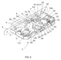
- the anti-panic lock 1 adapted to doors according to the invention comprises a case 2 delimited by a base 3, a cover 4, shown in Figure 1 , the base 3 and the cover 4 being arranged substantially parallel to each other, side walls 2a and a front 5 arranged substantially orthogonal to the base 3 and to the cover 4, a lever 6 that may be operated by a cylinder not shown in the figures, a latch 7 that may be operated by a first handle or a second handle not shown in the figures or the cylinder not shown in the figures, and a trigger element9, arranged between the lever 6 and the latch 7.
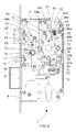
- the trigger element9 shown in Figures 2 to 4 , comprises a first part 9a that, in an initial open-door position not shown in the figures, projects out in relation to the front 5 towards the outside of the anti-panic lock 1, and a second part 9b that is arranged housed inside the case 2, the second part 9b including a groove 9c that cooperates with a projection 57 fixed to the base 3 to guide the movement of the trigger element9.
- the anti-panic lock 1 comprises means 100 for transmitting the movement associated to the cylinder or the corresponding handle towards the latch 7 or towards the lever 6, the transmission means 100 comprising a first pusher 20 adapted to be operated by the first handle, a second pusher 21 adapted to be operated by the second handle, and at least one slide member 110 adapted so that it may be moved, operated by the first pusher 20 or by the second pusher 21.
- the slide member 110 is arranged coupled to the lever 6, the slide member 110 including a groove 65, shown in Figures 2 , 3 , 10 and 12 , along which moves a connector member 55, shown in Figures 2 , 3 and 10 , inserted in the lever 6.
- the anti-panic lock 1 also includes a traction spring, not shown in the figures, one of the ends of which is arranged fixed to the base 3 of the case 2 and the other end is arranged fixed to one end of the slide member 110.
- the trigger element 9 keeps the slide member 110 locked.
- the trigger element 9 moves towards inside of the case 2, with the result that the first part 9a retracts and is housed in said case 2, and the second part 9b comes into contact with a switch 10, shown in Figure 2 , generating an electrical signal that indicates that the door is closed against the frame of the door and, at the same time, releases the slide member 110.
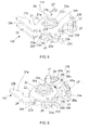
- the slide member 110 comprises a first cam 60, shown in detail in Figures 10 to 12 , which has a surface 60a that is arranged facing the second pusher 21 in a locked-door position, an intermediate cam 40, shown in detail in Figure 13 , which is arranged supported on a second surface 60b of the first cam 60 and a second cam 30, shown in detail in Figure 14 , which is arranged supported on the intermediate cam 40 and which includes a surface 30a, shown in Figure 11 , facing the first pusher 20 in the locked-door position, the cams 30,40,60 being arranged coupled to each other.
- the slide member 110 also includes guide means 80 that include a first corresponding groove 31,41,61 that collaborates with a substantially cylindrical guide member 53, shown in Figures 2 to 4 , 10 and 11 , fixed to the base 3 of the case 2 of the anti-panic lock 1, to guide the movement of the slide member 110 in relation to said base 3.
- the guide means 80 comprise in the first cam 60 a second groove 64 substantially parallel to the first groove 61, which collaborates with a substantially cylindrical guide member 54 fixed to the case 2, which also acts as a support for the first cam 60, and a projection 66, shown in Figures 1 to 3 , that collaborates with a groove 2b arranged on one of the walls 2a of the case 2 for the movement of the slide member 110 inside the case 2.
- the intermediate cam 40 comprises a projection 45, shown in Figures 2 , 4 , 10 , and 13 , that acts as a stopper when the lock is in the locked position, preventing said latch 7 from moving towards the inside of the case 2.
- both the intermediate cam 40 and the first cam 30 include on one end a respective housing 36,46 delimited by a surface 36b,46b, shown in Figures 13 and 14 , substantially sloping in relation to the direction of movement of the latch 7.
- the latch 7 comprises an internal part, not visible in the figures, housed inside the case 2, which includes a projection, not visible in the figures, which collaborates with the surface 36b,46b of the intermediate cam 40, with the result that the movement of the slide member 110 brings about the movement of the latch 7.
- the slide member 110 comprises three cams 30,40,60, in other embodiments not shown in the Figures, it may comprise two cams or even be made of a single piece.
- the first pusher 20 shown in detail in Figures 5,6 , 8 and 11 , comprises a plate 20a that includes an arm 20b adapted to move the slide member 110 when the first handle is operated and an opening 20c with a rectangular cross-section, in which a follower 26 is coupled.
- the second pusher 21, shown in detail in Figures 5 and 11 comprises a second plate 21 a that includes a second arm 21 b adapted to move the slide member 110 when the second handle is operated, and an opening 21 c with a rectangular cross-section, in which a follower 26 is coupled.
- the followers 26, shown in detail in Figure 10 each comprise a central part 26b with a substantially rectangular cross-section that is arranged inserted in the opening 20c, 21 c of the corresponding pusher 20,21, and a longitudinal housing 26a in which is coupled a shaft of the corresponding handle, with the result that the followers 26 and, therefore, the respective pushers 20,21 rotate independently of each other.
- the anti-panic lock 1 comprises stoppers 29, shown in Figures 2 to 4 and 10 , fixed to the base 3, which collaborate with respective recesses 20f,21f in the respective pusher 20,21 to delimit the rotation of the pushers 20,21.
- the transmission means 100 also comprise an intermediate plate 22, shown in Figures 5 to 7 , which is arranged, in the embodiment described in the figures, fixed to the first pusher 20 by coupling pins 28, and a return spring 25 that is arranged housed inside the intermediate plate 22.
- the intermediate plate 22 includes a substantially concentric housing 22a in which is housed the return spring 25, preferably a torque spring, and a side opening 23 through which a first branch 25a, and a second branch 25b of the spring 25 project out, the ends 23a,23b of the opening 23 defining the limits of rotation of the handles.
- the intermediate plate 22 also has a central hole 22b in which the respective followers 26 coupled to the first pusher 20 and the second pusher 21 are partially coupled.
- the anti-panic lock 1 comprises a stopper 56, shown in Figures 2 and 4 , that is arranged inserted in the base 3 of the case 2 against which the second branch 25b acts permanently as a stopper.
- the first pusher 20 comprises a projection 20d, which extends towards the base 3, against which both branches 25a, 25b of the spring 25 act as stoppers in a position in which the handles are not operated, and against which only the first branch 25a acts as a stopper when the first handle has been operated.
- the second pusher 21 also comprises a projection 21 d fixed to the second plate 21 a, which extends towards the cover 4, against which both branches 25a,25b of the spring 25 act as stoppers in a position in which the handles are not operated, and against which only the first branch 25a acts as a stopper when the second handle has been operated.
- the projection 20d of the first pusher 20 and the projection 21d of second pusher 21 are arranged substantially aligned.
- the anti-panic lock 1 of the invention comprises clutch means 90 that couple both pushers 20,21 for the simultaneous rotation of both handles regardless of which handle is operated by the user.
- the clutch means 90 shown in Figures 2 to 4 , comprise a support 91 fixed to the base 3, a motor 92 supported by the support 91, an endless screw 93 coupled to the motor 92, an actuator 94 fixed at one end in a pivoting manner to the support 91 and which includes a contact member 94b that is in contact with the endless screw 93, and a clutch 95, shown in Figures 4 and 6 , that couples the pushers 20,21 when operated by the actuator 94.
- the actuator 94 is made of flexible material.
- the contact member 94 has a substantially orthogonal cross-section, its width being smaller than the distance between two consecutive threads of the endless screw 93.
- the actuator 94 shown in Figures 2 and 4 , comprises a base 94d that includes the contact surface 94 and which is arranged supported on the base 3 of the case 2, a first projection 94a that is fixed substantially orthogonal to the base 94d of the actuator 94, it being inserted in a hole of said base 94, by which the actuator 94 is fixed in a pivoting manner to the support 91, and a second projection 94f from which the contact member 94b is arranged substantially orthogonal to the endless screw 93.
- the clutch 95 is housed in the intermediate plate 22 of the transmission means 100, comprising a substantially rectangular first part 95a, and a second part 95b with a substantially rectangular cross-section, and a greater width than the first part 95a. Additionally, the intermediate plate 22, shown in Figures 6 and 7 , includes a cavity 24 that has a first part 24a inside which is housed the second part 95b of the clutch 95, and a second part 24b connected to the first part 24a and the exterior, with a smaller width than the first part 24a, inside which is housed the first part 95a of the clutch 95.
- the clutch 95 includes in the second part 95 a housing 95c in which is housed a spring 97.
- the first pusher 21 includes, on the end opposite the arm 21 b, grooves 21 e shown in Figure 5 where stoppers 27 are arranged inserted, arranged facing the second pusher 20 and which delimit a housing 27b, shown in Figure 6 , between them.
- both pushers 20,21 are declutched, the motor 91 is not operating, and the actuator 94 acts on the clutch 95, in particular on the first part 95a, with the result that the clutch 95 compresses the spring 96, being housed entirely in the cavity 24 of the intermediate plate 22, each pusher 20,21 being capable of rotating independently in relation to the other pusher 21,20, given that the respective projection 27 of the first pusher 21 acts as a stopper, preventing the clutch 95 from expanding outside the cavity 24. Subsequently, the respective pusher 20,21 returns to the initial position by the return spring 25.
- the endless screw 93 rotates in an anti-clockwise direction, with the result that the contact member 94b of the actuator 94 is moved by the endless screw 93 in a direction towards the motor 91, with the result that both pushers 20,21 are coupled to each other, rotating jointly when either of the two handles is operated.
- the second part 95b of the clutch 95 acts as a stopper against the first part 24a of the cavity 24 of the intermediate plate 22, with the result that the first part 95a is partially housed in the housing 27b delimited by the stoppers 27, with the result that both pushers 20,21 are clutched together.
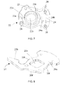
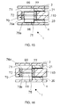
- the anti-panic release means 70 shown in detail in Figures 15 and 16 , comprise a sleeve 71 that is arranged inserted in the slide member 110, for which purpose the respective cams 30,40,60 comprised in the slide member 110 respectively include a hole 37,45,67 in which the sleeve 71 is inserted fixed.
- the anti-panic release means 70 also comprise a substantially cylindrical positioning member 75, inserted in a movable manner in the sleeve 71.
- the sleeve 71 includes an inner ring-shaped groove 72 in which is housed an elastic means 77, and the positioning member 75 also comprises a first outer groove 76a and a second outer groove 76b, both of them ring-shaped grooves, separated from each other by a certain distance.
- the elastic means 77 preferably includes an elastic seal. In other embodiments the elastic means 77 may include elastic washers, a spring, ring seals, etc.
- the positioning member 75 is arranged inserted in the sleeve 71 with the result that the elastic seal 77 inserted in the inner groove 72 of the sleeve 71 is housed in the first outer groove 76a of said positioning member 75, the positioning member 75 projecting out in relation to the slide member 110, and in particular in relation to the free surface 60a of the first cam 60, being supported on the base 3 of the case 2 of the anti-panic lock 1.
- the positioning member 75 is arranged inserted in the sleeve 71 with the result that the elastic seal 77, inserted in the inner groove 72 of the sleeve 71 is housed tightly in the second outer groove 76b of the positioning member 75, the positioning member 75 projecting out in relation to the slide member 110, in particular in relation to the free surface 30a of the second cam 30, it being supported on the cover 4 of the case 2 of the anti-panic lock 1.
- both the cover 4 and the base 3 of the case 2 respectively comprise a hole 96, shown in Figures 1 , 15 and 16 , arranged concentric to each other and to the positioning member 75, with the result that by introducing a suitable tool through the corresponding hole 96, the positioning member 75 may be moved from one position to another, thereby allowing the user to change, quickly and easily from the outside of the anti-panic lock 1, the configuration of said anti-panic lock 1 in order to obtain an anti-panic lock 1 that is unlocked when the first handle is operated or is unlocked when the second handle is operated.
Landscapes
- Engineering & Computer Science (AREA)
- Structural Engineering (AREA)
- Business, Economics & Management (AREA)
- Emergency Management (AREA)
- Lock And Its Accessories (AREA)
Priority Applications (1)
| Application Number | Priority Date | Filing Date | Title |
|---|---|---|---|
| PL11382118T PL2385199T3 (pl) | 2010-05-04 | 2011-04-18 | Zamek antypaniczny przystosowany do drzwi |
Applications Claiming Priority (1)
| Application Number | Priority Date | Filing Date | Title |
|---|---|---|---|
| ES201030423U ES1073001Y (es) | 2010-05-04 | 2010-05-04 | Cerradura anti-panico adaptada a puertas |
Publications (3)
| Publication Number | Publication Date |
|---|---|
| EP2385199A2 true EP2385199A2 (de) | 2011-11-09 |
| EP2385199A3 EP2385199A3 (de) | 2015-04-08 |
| EP2385199B1 EP2385199B1 (de) | 2017-10-18 |
Family
ID=42824844
Family Applications (1)
| Application Number | Title | Priority Date | Filing Date |
|---|---|---|---|
| EP11382118.5A Active EP2385199B1 (de) | 2010-05-04 | 2011-04-18 | Für Türen angepasstes Antipanik-Schloss |
Country Status (3)
| Country | Link |
|---|---|
| EP (1) | EP2385199B1 (de) |
| ES (1) | ES1073001Y (de) |
| PL (1) | PL2385199T3 (de) |
Cited By (5)
| Publication number | Priority date | Publication date | Assignee | Title |
|---|---|---|---|---|
| DE202013008983U1 (de) * | 2013-01-11 | 2014-04-15 | Bks Gmbh | Schloss |
| US20170152681A1 (en) * | 2015-11-27 | 2017-06-01 | Tong Lung Metal Industry Co., Ltd. | Door lock having locking mechanism |
| FR3045091A1 (fr) * | 2015-12-11 | 2017-06-16 | Dubois Ind | Serrure actionnable par une premiere commande telle qu'une barre anti-panique et par une deuxieme commande a cle |
| WO2019161694A1 (zh) * | 2018-02-26 | 2019-08-29 | 一诺电器有限公司 | 一种智能锁反锁结构 |
| WO2020040688A1 (en) * | 2018-08-23 | 2020-02-27 | Stendals El Ab | Locking device with a mechanical arrangement for selecting an active side of a door |
Families Citing this family (1)
| Publication number | Priority date | Publication date | Assignee | Title |
|---|---|---|---|---|
| IT201900009867A1 (it) * | 2019-06-24 | 2020-12-24 | Pba S P A | Struttura di serratura |
Citations (5)
| Publication number | Priority date | Publication date | Assignee | Title |
|---|---|---|---|---|
| ES2066673A2 (es) | 1992-07-20 | 1995-03-01 | Talleres Escoriaza Sa | Cerradura antipanico perfeccionada. |
| ES2048616B1 (es) | 1991-06-05 | 1997-10-16 | Cerrajera Ind | Dispositivo de seguridad para cerraduras de picaporte. |
| ES2211277B1 (es) | 2002-04-10 | 2005-10-01 | La Industrial Cerrajera, S.A. | Cerradura de seguridad con doble control del picaporte y funcion antipanico. |
| US20080066505A1 (en) | 2006-09-19 | 2008-03-20 | Imperial Usa, Ltd. | Lock assembly with anti-panic feature and associated method |
| EP1969525A1 (de) | 2005-12-23 | 2008-09-17 | Ingenia Holdings (UK)Limited | Optische authentifizierung |
Family Cites Families (4)
| Publication number | Priority date | Publication date | Assignee | Title |
|---|---|---|---|---|
| NL1022523C2 (nl) * | 2003-01-30 | 2004-08-16 | Lips Nederland B V | Slotsamenstel. |
| DE20307120U1 (de) * | 2003-04-30 | 2003-07-10 | Gretsch-Unitas GmbH Baubeschläge, 71254 Ditzingen | Schloss |
| WO2009087464A1 (en) * | 2007-12-26 | 2009-07-16 | Goldtec Migun 2005 Ltd. | Mortise lock |
| DE202009008432U1 (de) * | 2009-06-15 | 2009-08-20 | Bks Gmbh | Schloss |
-
2010
- 2010-05-04 ES ES201030423U patent/ES1073001Y/es not_active Expired - Fee Related
-
2011
- 2011-04-18 EP EP11382118.5A patent/EP2385199B1/de active Active
- 2011-04-18 PL PL11382118T patent/PL2385199T3/pl unknown
Patent Citations (5)
| Publication number | Priority date | Publication date | Assignee | Title |
|---|---|---|---|---|
| ES2048616B1 (es) | 1991-06-05 | 1997-10-16 | Cerrajera Ind | Dispositivo de seguridad para cerraduras de picaporte. |
| ES2066673A2 (es) | 1992-07-20 | 1995-03-01 | Talleres Escoriaza Sa | Cerradura antipanico perfeccionada. |
| ES2211277B1 (es) | 2002-04-10 | 2005-10-01 | La Industrial Cerrajera, S.A. | Cerradura de seguridad con doble control del picaporte y funcion antipanico. |
| EP1969525A1 (de) | 2005-12-23 | 2008-09-17 | Ingenia Holdings (UK)Limited | Optische authentifizierung |
| US20080066505A1 (en) | 2006-09-19 | 2008-03-20 | Imperial Usa, Ltd. | Lock assembly with anti-panic feature and associated method |
Cited By (7)
| Publication number | Priority date | Publication date | Assignee | Title |
|---|---|---|---|---|
| DE202013008983U1 (de) * | 2013-01-11 | 2014-04-15 | Bks Gmbh | Schloss |
| US20170152681A1 (en) * | 2015-11-27 | 2017-06-01 | Tong Lung Metal Industry Co., Ltd. | Door lock having locking mechanism |
| FR3045091A1 (fr) * | 2015-12-11 | 2017-06-16 | Dubois Ind | Serrure actionnable par une premiere commande telle qu'une barre anti-panique et par une deuxieme commande a cle |
| WO2019161694A1 (zh) * | 2018-02-26 | 2019-08-29 | 一诺电器有限公司 | 一种智能锁反锁结构 |
| WO2020040688A1 (en) * | 2018-08-23 | 2020-02-27 | Stendals El Ab | Locking device with a mechanical arrangement for selecting an active side of a door |
| US12006727B2 (en) | 2018-08-23 | 2024-06-11 | Stendals El Ab | Locking device with a mechanical arrangement for selecting an active side of a door |
| AU2019324324B2 (en) * | 2018-08-23 | 2025-07-24 | Stendals El Ab | Locking device with a mechanical arrangement for selecting an active side of a door |
Also Published As
| Publication number | Publication date |
|---|---|
| PL2385199T3 (pl) | 2018-03-30 |
| EP2385199A3 (de) | 2015-04-08 |
| ES1073001U (es) | 2010-10-19 |
| ES1073001Y (es) | 2011-02-07 |
| EP2385199B1 (de) | 2017-10-18 |
Similar Documents
| Publication | Publication Date | Title |
|---|---|---|
| EP2385199B1 (de) | Für Türen angepasstes Antipanik-Schloss | |
| US10662674B2 (en) | Structures of electronic lock | |
| EP2570574B1 (de) | Elektromagnetisch betätigtes Schloss | |
| US10563434B2 (en) | Locking unit for a motor vehicle | |
| US20140191516A1 (en) | Side mounted privacy lock for a residential door | |
| JP2011500995A (ja) | ラッチアクチュエータ及びそれを用いるラッチ | |
| WO2018128979A1 (en) | Vehicle interior component | |
| US11525279B2 (en) | Handle device | |
| CN112823232A (zh) | 闩锁 | |
| DK2397628T3 (en) | LOCKING DEVICE WITH LOCKING MECHANISM | |
| US5896764A (en) | Lock adapted to be accommodated within the thickness of an opening panel | |
| EP2385198B1 (de) | Für Türen angepasstes elektromechanisches Schloss | |
| US7963133B2 (en) | Cylinder lock and unlocking device comprising thereof | |
| US11066848B2 (en) | Push to lock and unlock door lock | |
| EP3771790B1 (de) | Schloss | |
| WO2003091518A8 (en) | A combination lock | |
| KR200423328Y1 (ko) | 패 닉 기능이 내장된 모 티 스 장치 | |
| JP6100125B2 (ja) | アンチパニック式自動施錠錠 | |
| CN112955618B (zh) | 用于驱动机构的锁头 | |
| RU2295019C2 (ru) | Замок кодовый с механизмом последовательного ввода | |
| RU2697341C2 (ru) | Многофункциональная ручка для выходных дверей в случае пожара | |
| GB2593480A (en) | An electronic locking device | |
| JP2009102956A (ja) | シリンダ錠及びこれを備えた解錠装置 | |
| NZ748525A (en) | A lock | |
| JP2009102957A (ja) | シリンダ錠及びこれを備えた解錠装置 |
Legal Events
| Date | Code | Title | Description |
|---|---|---|---|
| AK | Designated contracting states |
Kind code of ref document: A2 Designated state(s): AL AT BE BG CH CY CZ DE DK EE ES FI FR GB GR HR HU IE IS IT LI LT LU LV MC MK MT NL NO PL PT RO RS SE SI SK SM TR |
|
| AX | Request for extension of the european patent |
Extension state: BA ME |
|
| PUAI | Public reference made under article 153(3) epc to a published international application that has entered the european phase |
Free format text: ORIGINAL CODE: 0009012 |
|
| PUAL | Search report despatched |
Free format text: ORIGINAL CODE: 0009013 |
|
| AK | Designated contracting states |
Kind code of ref document: A3 Designated state(s): AL AT BE BG CH CY CZ DE DK EE ES FI FR GB GR HR HU IE IS IT LI LT LU LV MC MK MT NL NO PL PT RO RS SE SI SK SM TR |
|
| AX | Request for extension of the european patent |
Extension state: BA ME |
|
| RIC1 | Information provided on ipc code assigned before grant |
Ipc: E05B 65/10 20060101AFI20150305BHEP Ipc: E05B 59/00 20060101ALI20150305BHEP Ipc: E05B 63/16 20060101ALI20150305BHEP Ipc: E05B 47/00 20060101ALI20150305BHEP Ipc: E05B 63/20 20060101ALI20150305BHEP |
|
| 17P | Request for examination filed |
Effective date: 20151008 |
|
| RBV | Designated contracting states (corrected) |
Designated state(s): AL AT BE BG CH CY CZ DE DK EE ES FI FR GB GR HR HU IE IS IT LI LT LU LV MC MK MT NL NO PL PT RO RS SE SI SK SM TR |
|
| GRAP | Despatch of communication of intention to grant a patent |
Free format text: ORIGINAL CODE: EPIDOSNIGR1 |
|
| INTG | Intention to grant announced |
Effective date: 20170518 |
|
| GRAS | Grant fee paid |
Free format text: ORIGINAL CODE: EPIDOSNIGR3 |
|
| GRAA | (expected) grant |
Free format text: ORIGINAL CODE: 0009210 |
|
| AK | Designated contracting states |
Kind code of ref document: B1 Designated state(s): AL AT BE BG CH CY CZ DE DK EE ES FI FR GB GR HR HU IE IS IT LI LT LU LV MC MK MT NL NO PL PT RO RS SE SI SK SM TR |
|
| REG | Reference to a national code |
Ref country code: GB Ref legal event code: FG4D |
|
| REG | Reference to a national code |
Ref country code: CH Ref legal event code: EP |
|
| REG | Reference to a national code |
Ref country code: AT Ref legal event code: REF Ref document number: 938098 Country of ref document: AT Kind code of ref document: T Effective date: 20171115 Ref country code: IE Ref legal event code: FG4D |
|
| REG | Reference to a national code |
Ref country code: DE Ref legal event code: R096 Ref document number: 602011042474 Country of ref document: DE |
|
| REG | Reference to a national code |
Ref country code: NL Ref legal event code: MP Effective date: 20171018 |
|
| REG | Reference to a national code |
Ref country code: LT Ref legal event code: MG4D |
|
| REG | Reference to a national code |
Ref country code: AT Ref legal event code: MK05 Ref document number: 938098 Country of ref document: AT Kind code of ref document: T Effective date: 20171018 |
|
| PG25 | Lapsed in a contracting state [announced via postgrant information from national office to epo] |
Ref country code: NL Free format text: LAPSE BECAUSE OF FAILURE TO SUBMIT A TRANSLATION OF THE DESCRIPTION OR TO PAY THE FEE WITHIN THE PRESCRIBED TIME-LIMIT Effective date: 20171018 |
|
| REG | Reference to a national code |
Ref country code: FR Ref legal event code: PLFP Year of fee payment: 8 |
|
| PG25 | Lapsed in a contracting state [announced via postgrant information from national office to epo] |
Ref country code: SE Free format text: LAPSE BECAUSE OF FAILURE TO SUBMIT A TRANSLATION OF THE DESCRIPTION OR TO PAY THE FEE WITHIN THE PRESCRIBED TIME-LIMIT Effective date: 20171018 Ref country code: FI Free format text: LAPSE BECAUSE OF FAILURE TO SUBMIT A TRANSLATION OF THE DESCRIPTION OR TO PAY THE FEE WITHIN THE PRESCRIBED TIME-LIMIT Effective date: 20171018 Ref country code: LT Free format text: LAPSE BECAUSE OF FAILURE TO SUBMIT A TRANSLATION OF THE DESCRIPTION OR TO PAY THE FEE WITHIN THE PRESCRIBED TIME-LIMIT Effective date: 20171018 Ref country code: ES Free format text: LAPSE BECAUSE OF FAILURE TO SUBMIT A TRANSLATION OF THE DESCRIPTION OR TO PAY THE FEE WITHIN THE PRESCRIBED TIME-LIMIT Effective date: 20171018 Ref country code: NO Free format text: LAPSE BECAUSE OF FAILURE TO SUBMIT A TRANSLATION OF THE DESCRIPTION OR TO PAY THE FEE WITHIN THE PRESCRIBED TIME-LIMIT Effective date: 20180118 |
|
| PG25 | Lapsed in a contracting state [announced via postgrant information from national office to epo] |
Ref country code: BG Free format text: LAPSE BECAUSE OF FAILURE TO SUBMIT A TRANSLATION OF THE DESCRIPTION OR TO PAY THE FEE WITHIN THE PRESCRIBED TIME-LIMIT Effective date: 20180118 Ref country code: AT Free format text: LAPSE BECAUSE OF FAILURE TO SUBMIT A TRANSLATION OF THE DESCRIPTION OR TO PAY THE FEE WITHIN THE PRESCRIBED TIME-LIMIT Effective date: 20171018 Ref country code: IS Free format text: LAPSE BECAUSE OF FAILURE TO SUBMIT A TRANSLATION OF THE DESCRIPTION OR TO PAY THE FEE WITHIN THE PRESCRIBED TIME-LIMIT Effective date: 20180218 Ref country code: LV Free format text: LAPSE BECAUSE OF FAILURE TO SUBMIT A TRANSLATION OF THE DESCRIPTION OR TO PAY THE FEE WITHIN THE PRESCRIBED TIME-LIMIT Effective date: 20171018 Ref country code: HR Free format text: LAPSE BECAUSE OF FAILURE TO SUBMIT A TRANSLATION OF THE DESCRIPTION OR TO PAY THE FEE WITHIN THE PRESCRIBED TIME-LIMIT Effective date: 20171018 Ref country code: GR Free format text: LAPSE BECAUSE OF FAILURE TO SUBMIT A TRANSLATION OF THE DESCRIPTION OR TO PAY THE FEE WITHIN THE PRESCRIBED TIME-LIMIT Effective date: 20180119 Ref country code: RS Free format text: LAPSE BECAUSE OF FAILURE TO SUBMIT A TRANSLATION OF THE DESCRIPTION OR TO PAY THE FEE WITHIN THE PRESCRIBED TIME-LIMIT Effective date: 20171018 |
|
| REG | Reference to a national code |
Ref country code: DE Ref legal event code: R097 Ref document number: 602011042474 Country of ref document: DE |
|
| PG25 | Lapsed in a contracting state [announced via postgrant information from national office to epo] |
Ref country code: DK Free format text: LAPSE BECAUSE OF FAILURE TO SUBMIT A TRANSLATION OF THE DESCRIPTION OR TO PAY THE FEE WITHIN THE PRESCRIBED TIME-LIMIT Effective date: 20171018 Ref country code: SK Free format text: LAPSE BECAUSE OF FAILURE TO SUBMIT A TRANSLATION OF THE DESCRIPTION OR TO PAY THE FEE WITHIN THE PRESCRIBED TIME-LIMIT Effective date: 20171018 Ref country code: EE Free format text: LAPSE BECAUSE OF FAILURE TO SUBMIT A TRANSLATION OF THE DESCRIPTION OR TO PAY THE FEE WITHIN THE PRESCRIBED TIME-LIMIT Effective date: 20171018 Ref country code: CZ Free format text: LAPSE BECAUSE OF FAILURE TO SUBMIT A TRANSLATION OF THE DESCRIPTION OR TO PAY THE FEE WITHIN THE PRESCRIBED TIME-LIMIT Effective date: 20171018 |
|
| PLBE | No opposition filed within time limit |
Free format text: ORIGINAL CODE: 0009261 |
|
| STAA | Information on the status of an ep patent application or granted ep patent |
Free format text: STATUS: NO OPPOSITION FILED WITHIN TIME LIMIT |
|
| PG25 | Lapsed in a contracting state [announced via postgrant information from national office to epo] |
Ref country code: SM Free format text: LAPSE BECAUSE OF FAILURE TO SUBMIT A TRANSLATION OF THE DESCRIPTION OR TO PAY THE FEE WITHIN THE PRESCRIBED TIME-LIMIT Effective date: 20171018 Ref country code: IT Free format text: LAPSE BECAUSE OF FAILURE TO SUBMIT A TRANSLATION OF THE DESCRIPTION OR TO PAY THE FEE WITHIN THE PRESCRIBED TIME-LIMIT Effective date: 20171018 Ref country code: RO Free format text: LAPSE BECAUSE OF FAILURE TO SUBMIT A TRANSLATION OF THE DESCRIPTION OR TO PAY THE FEE WITHIN THE PRESCRIBED TIME-LIMIT Effective date: 20171018 |
|
| 26N | No opposition filed |
Effective date: 20180719 |
|
| PG25 | Lapsed in a contracting state [announced via postgrant information from national office to epo] |
Ref country code: SI Free format text: LAPSE BECAUSE OF FAILURE TO SUBMIT A TRANSLATION OF THE DESCRIPTION OR TO PAY THE FEE WITHIN THE PRESCRIBED TIME-LIMIT Effective date: 20171018 Ref country code: MC Free format text: LAPSE BECAUSE OF FAILURE TO SUBMIT A TRANSLATION OF THE DESCRIPTION OR TO PAY THE FEE WITHIN THE PRESCRIBED TIME-LIMIT Effective date: 20171018 |
|
| REG | Reference to a national code |
Ref country code: CH Ref legal event code: PL |
|
| REG | Reference to a national code |
Ref country code: BE Ref legal event code: MM Effective date: 20180430 |
|
| REG | Reference to a national code |
Ref country code: IE Ref legal event code: MM4A |
|
| PG25 | Lapsed in a contracting state [announced via postgrant information from national office to epo] |
Ref country code: LU Free format text: LAPSE BECAUSE OF NON-PAYMENT OF DUE FEES Effective date: 20180418 |
|
| PG25 | Lapsed in a contracting state [announced via postgrant information from national office to epo] |
Ref country code: BE Free format text: LAPSE BECAUSE OF NON-PAYMENT OF DUE FEES Effective date: 20180430 Ref country code: CH Free format text: LAPSE BECAUSE OF NON-PAYMENT OF DUE FEES Effective date: 20180430 Ref country code: LI Free format text: LAPSE BECAUSE OF NON-PAYMENT OF DUE FEES Effective date: 20180430 |
|
| PG25 | Lapsed in a contracting state [announced via postgrant information from national office to epo] |
Ref country code: IE Free format text: LAPSE BECAUSE OF NON-PAYMENT OF DUE FEES Effective date: 20180418 |
|
| PG25 | Lapsed in a contracting state [announced via postgrant information from national office to epo] |
Ref country code: MT Free format text: LAPSE BECAUSE OF NON-PAYMENT OF DUE FEES Effective date: 20180418 |
|
| PG25 | Lapsed in a contracting state [announced via postgrant information from national office to epo] |
Ref country code: TR Free format text: LAPSE BECAUSE OF FAILURE TO SUBMIT A TRANSLATION OF THE DESCRIPTION OR TO PAY THE FEE WITHIN THE PRESCRIBED TIME-LIMIT Effective date: 20171018 |
|
| PG25 | Lapsed in a contracting state [announced via postgrant information from national office to epo] |
Ref country code: PT Free format text: LAPSE BECAUSE OF FAILURE TO SUBMIT A TRANSLATION OF THE DESCRIPTION OR TO PAY THE FEE WITHIN THE PRESCRIBED TIME-LIMIT Effective date: 20171018 Ref country code: HU Free format text: LAPSE BECAUSE OF FAILURE TO SUBMIT A TRANSLATION OF THE DESCRIPTION OR TO PAY THE FEE WITHIN THE PRESCRIBED TIME-LIMIT; INVALID AB INITIO Effective date: 20110418 |
|
| PG25 | Lapsed in a contracting state [announced via postgrant information from national office to epo] |
Ref country code: MK Free format text: LAPSE BECAUSE OF NON-PAYMENT OF DUE FEES Effective date: 20171018 Ref country code: CY Free format text: LAPSE BECAUSE OF FAILURE TO SUBMIT A TRANSLATION OF THE DESCRIPTION OR TO PAY THE FEE WITHIN THE PRESCRIBED TIME-LIMIT Effective date: 20171018 |
|
| PG25 | Lapsed in a contracting state [announced via postgrant information from national office to epo] |
Ref country code: AL Free format text: LAPSE BECAUSE OF FAILURE TO SUBMIT A TRANSLATION OF THE DESCRIPTION OR TO PAY THE FEE WITHIN THE PRESCRIBED TIME-LIMIT Effective date: 20171018 |
|
| PGFP | Annual fee paid to national office [announced via postgrant information from national office to epo] |
Ref country code: DE Payment date: 20250429 Year of fee payment: 15 Ref country code: PL Payment date: 20250401 Year of fee payment: 15 |
|
| PGFP | Annual fee paid to national office [announced via postgrant information from national office to epo] |
Ref country code: GB Payment date: 20250428 Year of fee payment: 15 |
|
| PGFP | Annual fee paid to national office [announced via postgrant information from national office to epo] |
Ref country code: FR Payment date: 20250425 Year of fee payment: 15 |