EP2384982A1 - Verfahren zum Betrieb einer Tiefziehverpackungsmaschine - Google Patents
Verfahren zum Betrieb einer Tiefziehverpackungsmaschine Download PDFInfo
- Publication number
- EP2384982A1 EP2384982A1 EP11003720A EP11003720A EP2384982A1 EP 2384982 A1 EP2384982 A1 EP 2384982A1 EP 11003720 A EP11003720 A EP 11003720A EP 11003720 A EP11003720 A EP 11003720A EP 2384982 A1 EP2384982 A1 EP 2384982A1
- Authority
- EP
- European Patent Office
- Prior art keywords
- film
- space
- food
- product
- cover film
- Prior art date
- Legal status (The legal status is an assumption and is not a legal conclusion. Google has not performed a legal analysis and makes no representation as to the accuracy of the status listed.)
- Granted
Links
Images

Classifications
-
- B—PERFORMING OPERATIONS; TRANSPORTING
- B65—CONVEYING; PACKING; STORING; HANDLING THIN OR FILAMENTARY MATERIAL
- B65B—MACHINES, APPARATUS OR DEVICES FOR, OR METHODS OF, PACKAGING ARTICLES OR MATERIALS; UNPACKING
- B65B7/00—Closing containers or receptacles after filling
- B65B7/16—Closing semi-rigid or rigid containers or receptacles not deformed by, or not taking-up shape of, contents, e.g. boxes or cartons
- B65B7/162—Closing semi-rigid or rigid containers or receptacles not deformed by, or not taking-up shape of, contents, e.g. boxes or cartons by feeding web material to securing means
- B65B7/164—Securing by heat-sealing
-
- B—PERFORMING OPERATIONS; TRANSPORTING
- B65—CONVEYING; PACKING; STORING; HANDLING THIN OR FILAMENTARY MATERIAL
- B65B—MACHINES, APPARATUS OR DEVICES FOR, OR METHODS OF, PACKAGING ARTICLES OR MATERIALS; UNPACKING
- B65B31/00—Packaging articles or materials under special atmospheric or gaseous conditions; Adding propellants to aerosol containers
- B65B31/02—Filling, closing, or filling and closing, containers or wrappers in chambers maintained under vacuum or superatmospheric pressure or containing a special atmosphere, e.g. of inert gas
- B65B31/025—Filling, closing, or filling and closing, containers or wrappers in chambers maintained under vacuum or superatmospheric pressure or containing a special atmosphere, e.g. of inert gas specially adapted for rigid or semi-rigid containers
- B65B31/028—Filling, closing, or filling and closing, containers or wrappers in chambers maintained under vacuum or superatmospheric pressure or containing a special atmosphere, e.g. of inert gas specially adapted for rigid or semi-rigid containers closed by a lid sealed to the upper rim of the container, e.g. tray-like container
-
- B—PERFORMING OPERATIONS; TRANSPORTING
- B65—CONVEYING; PACKING; STORING; HANDLING THIN OR FILAMENTARY MATERIAL
- B65B—MACHINES, APPARATUS OR DEVICES FOR, OR METHODS OF, PACKAGING ARTICLES OR MATERIALS; UNPACKING
- B65B9/00—Enclosing successive articles, or quantities of material, e.g. liquids or semiliquids, in flat, folded, or tubular webs of flexible sheet material; Subdividing filled flexible tubes to form packages
- B65B9/02—Enclosing successive articles, or quantities of material between opposed webs
- B65B9/04—Enclosing successive articles, or quantities of material between opposed webs one or both webs being formed with pockets for the reception of the articles, or of the quantities of material
- B65B9/045—Enclosing successive articles, or quantities of material between opposed webs one or both webs being formed with pockets for the reception of the articles, or of the quantities of material for single articles, e.g. tablets
Definitions
- the invention relates to a method for operating a packaging machine and to a packaging machine itself.
- a thin top film is heated in a sealing station of a thermoforming packaging machine and the heated film is placed over the product. During the evacuation process and then due to the pressure difference to the atmosphere, this film engages closely and gently on the product. This is only possible with evacuated packs. However, with many products, it is neither possible nor desirable to contact the products with a heated top film as this negatively affects the cooling time, shelf life and appearance of the product.
- Packaging is known in which a cover film is deformed in such a way that it is shaped towards the bottom of the package and thus provides a further space opposite the sealing plane, which can be filled with further products, wherein subsequently a second cover film mostly in printed form the packaging is just sealed.
- the shaped cover foil offers a higher stability of the whole Packaging and a good reclosability of the packaging after removing products from the lower packaging space and reclosing this space.
- the object of the present invention is to provide a method for operating a packaging machine, in which the disadvantages described above can be eliminated.
- the method also includes forming the first lidding film prior to feeding it into the first sealing station so that the heating of the lidding film necessary for deformation can cool back to the extent that the food, which is preferably cold or cool in the contact, is not heated.
- a second lidding film may be fed after the first sealing station in a second sealing station to be welded in the second sealing station to the first lidding film and / or the packing trough or fed into a common sealing station with the first formed lidding film.
- the space between the molded lid foil and the second lid foil can be evacuated and / or gassed.
- the inventive method preferably has a control that controls the amount of gas or gas mixture and / or the pressure inside the package in which the food is located and by means of which the parameters gas pressure or gas quantity are also adjustable.
- the distance between the bottom of the molded lidding film to the packing tray would be less than the product height. This overlap leads to a pressing force of the cover film on the product and thus to a fixation of the product within the package without exchange of atmosphere inside the package.
- an atmosphere exchange by evacuation and gassing it is possible to control the gas or gas pressure inside the package so that the molded lidding film is not raised so much that the effect of a force on the product is reduced too much, while prolonging the Halt zucchiniszeft.
- the shaped lidding film is preferably made in a thickness in a range of 70 ⁇ m to 120 ⁇ m in order to enhance the properties of the packaging container according to the invention, such as fixation of the product in the package the top of the product and fixation of the product additives lying on the product. It is also conceivable film thickness outside the specified range, if the films are formed as multilayer films and thus appropriate properties such as flexibility can be specially selected.
- a second lidding film can also be applied, which is preferably sealed in the sealing plane with the packing trough and the first lidding foil.
- This film can be made in a printed version, which displays information about the inside food, and is also suitable for applying labels or printing e.g. the expiration date.
- the thus existing second space between the first and second cover film can be evacuated and / or gassed and filled with other products.
- the packaging container preferably has a pack bottom suitably shaped for this purpose.
- a pack bottom suitably shaped for this purpose.
- FIG. 1 shows a schematic view of a thermoforming packaging machine 1.
- This has a forming station 2, a first sealing station 3, a second sealing station 4, a cross-cutting device 5 and longitudinal cutting device 6, which are arranged in this order in a direction R on a machine frame 7.
- a feed roller 8 On the input side is located on the machine frame 7, a feed roller 8, from which a lower film 9 is withdrawn.
- a packing trough 10 is formed in the lower film 9.
- a material reservoir 10 is provided, of which a first lid film 11 is deducted. Before the first cover film 11 is fed into the first sealing station 3, the first cover film 11 is formed in a cover film forming station 12.
- a second cover film 13 is withdrawn from a material storage 14 and fed to the second sealing station 4 and sealed in this station to the lower film 9 and / or first cover film 11.
- a discharge device 15 in the form of a conveyor belt is provided on the packaging machine 1, with the finished individualized packages 16 being transported away. Furthermore, the packaging machine 1 on a feed device, not shown, which engages the first web-shaped material 9 laterally and transported in the main working cycle in cycles in the direction of R.
- the feed device may e.g. be realized by laterally arranged transport chains.
- the first lid sheet 11 is formed so that the molded surface when feeding into the first sealing station 3 to the product 18 and also comes with this contact.
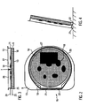
- FIG. 2 is a plan view of a package produced by the process according to the invention shown.
- product 18 eg pizza
- product additives 19 eg topping such as cheese, salami, ham, etc.
- the first molded lidding film 11 and the second lidding film 13 are sealed by means of a sealing seam 20 onto the lower film 9 formed into a packing trough 10.
- a partially (straight) edge 21 is provided on one side of the package 16.
- the first molded lidding film 13 is deep drawn in parallel in the region of the package bottom, so that an edge 22 is formed.
- Belde mutually parallel edges 21, 22 form the footprint for a standing package 18th
- FIG. 3 shows the plane 23 of the first molded lidding film 11 and the top level 24 of the product 18 with the product additives 19.
- the plane 23 lies below the plane 24. This ensures that the lidding film 11 with the product 18, 19 in Contact is because the cover film, when it is designed as a plastic film with a thickness of less than 120 ⁇ m, grants flexibility similar to a skin film and also partially rests on the product edge. This leads to a fixation of the product 18, 19 within the packing trough 10 and can over the transport of the package 16 beyond a constant distance from the product 18, 19 to the inside of the packaging container guarantee.
- a second component of the pressing force is generated via the external atmospheric pressure with respect to the vacuum present in the package interior 25.
- the space 25 between the packing trough 10 and the shaped lidding film 11 is evacuated and then fumigated again, so that the shaped lidding film 11 exerts a desired pressing force F on the product 18, 19.
- This force F is metered via the amount of gas or the gas pressure in the space 25 by means of a (not shown) control, preferably the machine control.
- the necessary parameters can be entered and stored by the operating personnel via an input unit (not shown) in the controller.
- machine settings for different products and production processes can be stored in recipes.
- the second cover film 13 is preferably applied flat on both films 9 and 11 and sealed with two films 9, 11. It is preferably colored to provide information on the product 18, 19 and / or to provide an area for labels 27 to be applied.
- the properties of the first and second lidding sheets 11, 13 may be different.
- the first cover sheet 11 is executed in a first embodiment without a barrier layer and the second cover sheet 13 is made airtight.
- the space 26 between two cover films 11, 13 can be gassed in order to increase the pressure force F of the first lid film 11 on the product 18, 19 and thus better control or control the desired pressing force F.
- the packaging according to the invention does not include a second cover film 13.
- the first cover film 11 is preferably made airtight with a barrier layer. Labeling and / or printing can also be carried out on the underside of the package bottom.
- the lidding film 11 is formed deeper than the product height (level 24) and abuts the top of the product 18, 19 while fixing the product additives 19 so that it is at a, as in FIG. 4 shown, standing position of the package does not lead to a change in position of the product additives 19 on the product 18.
- FIG. 4 is also through the edge 21 of the pack edge and the edge 22nd the bottom of the pack defined stand area shown.
- the edge 22 may also be partially or entirely formed as a surface in order to maximize the stability.
- the packaging container 16 is optimally displayed in a display shelf in retail markets to advertise with the on the second cover sheet 13 and attract the attention of the customer.
Landscapes
- Engineering & Computer Science (AREA)
- Mechanical Engineering (AREA)
- Chemical & Material Sciences (AREA)
- Dispersion Chemistry (AREA)
- Vacuum Packaging (AREA)
Abstract
Description
- Die Erfindung bezieht sich auf ein Verfahren zum Betrieb einer Verpackungsmaschine sowie auf eine Verpackungsmaschine selbst.
- Bei Produkten, auf denen sich weitere, meist kleinere lose Produktzusätze befinden, wie dies bei einer Pizza der Fall ist, und die in Kühltruhen oder Kühlregalen zum Verkauf angeboten werden, ist es üblich, dass diese Produkte in einer Folie unter Vakuum verpackt werden. Diese Art der Folienverpackung ermöglicht zum Einen eine längere Haltbarkeit des Produktinhaltes aufgrund des geringen Restsauerstoffes durch das Evakuieren und zum Anderen durch das enge Anliegen der Folie an dem Produkt, dass beispielsweise bei einer Pizza der Belag, bestehend aus vielen kleinen Produkten, fixiert ist, so dass dieser beim Transport nicht verrutschen kann und das Produkt seine gewünschte optisch ansprechende Form behält. Diese Fixierung durch das Anliegen der Folie wird durch einen hohen Druckunterschied zur Atmosphäre bewirkt.
- Speziell bei Skin-Verpackungen wird eine dünne Oberfolie in einer Siegelstation einer Tiefziehverpackungsmaschine erwärmt und die erwärmte Folie über das Produkt gelegt. Beim Evakuiervorgang und anschließend aufgrund der Druckdifferenz zur Atmosphäre legt sich diese Folie eng und schonend an das Produkt an. Dies ist nur bei evakuierten Packungen möglich. Es ist aber bei vielen Produkten weder möglich noch erwünscht, die Produkte mit einer erwärmten Oberfolle in Kontakt zu bringen, da dies die Kühlzeit, die Haltbarkeit und das Aussehen des Produktes negativ beeinflusst.
- Um die Haltbarkeit eines Produktes wie Pizza deutlich zu verlängern, ist es denkbar, das Innere der Verpackung nach dem Stand der Technik zu evakuieren und anschließend mit einem Gasgemisch wie Stickstoff und Kohlendloxid zu begasen. Dies führt aber zu einer Verpackung, die nicht mehr eng am Produkt anliegt und damit die Funktion der Fixierung des Produktes mit dem Belag wie bei einer Pizza nicht mehr erfüllt.
- Es sind Verpackungen bekannt, bei denen eine Deckelfolie so verformt wird, dass diese In Richtung Packungsboden geformt ist und somit einen weiteren Raum gegenüber der Siegelebene zur Verfügung stellt, der mit weiteren Produkten befüllt werden kann, wobei anschließend eine zweite Deckelfolie meist in bedruckter Form auf die Verpackung eben aufgesiegelt wird. Die geformte Deckelfolie bietet hierbei eine höhere Stabilität der gesamten Verpackung und eine gute Wiederverschließbarkeit der Verpackung nach der Entnahme von Produkten aus dem unteren Packungsraum und den Wiederverschluß dieses Raumes.
- Aufgabe der vorliegenden Erfindung ist es, ein Verfahren zum Betrieb einer Verpackungsmaschine zur Verfügung zu stellen, bei dem die vorstehend beschriebenen Nachteile beseitigt werden können.
- Diese Aufgabe wird gelöst durch ein Verfahren mit den Merkmalen des Anspruchs 1 bzw. durch eine Verpackungsmaschine nach Anspruch 7. Vorteilhafte Weiterbildungen der Erfindung sind in den Unteransprüchen angegeben.
- Das erfindungsgemäße Verfahren zum Betrieb auf einer Tiefziehverpackungsmaschine beinhaltet folgende Schritte:
- Formen einer Packungsmulde in eine erste Folie,
- Befüllen der Packungsmulde mit einem Lebensmittel,
- Verformen einer Deckelfolie,
- Zuführen von Packungsmulde mit Lebensmittel und Deckelfolie in eine Siegelstation,
- Evakuieren des Raumes zwischen Packungsmulde und Deckelfolie mit anschließenden einstellbarem Druck durch Gas oder Gasgemisch,
- Verschließen der Deckelfolie mit der Packungsmulde zu einer Verpackung, wobei beim anschließenden Belüften die Deckelfolie eine Kraft auf das Lebensmittel erzeugt.
- Das Verfahren beinhaltet auch das (Ver-)Formen der ersten Deckelfolie vor dem Zuführen in die erste Siegelstation, damit die zur Verformung notwendige Erwärmung der Deckelfolie soweit zurückkühlen kann, um das bei dem Kontakt vorzugsweise kalte oder kühle Lebensmittel nicht zu erwärmen.
- Eine zweite Deckelfolie kann nach der ersten Siegelstation in einer zweiten Siegelstation zugeführt werden, um in der zweiten Siegelstation mit der ersten Deckelfolie und/oder der Packungsmulde verschweißt zu werden oder in eine gemeinsame Siegelstation mit der ersten geformten Deckelfolie zugeführt zu werden. Dabei kann der Raum zwischen der geformten Deckelfolie und der zweiten Deckelfolie evakuiert und/oder begast werden.
- Das erfindungsgemäße Verfahren weist vorzugsweise eine Steuerung auf, die die Menge des Gases oder Gasgemisches und/oder den Druck im Packungsinneren, in dem sich das Lebensmittel befindet, steuert und mittels derer die Parameter Gasdruck oder Gasmenge auch einstellbar sind. So kann eine optimale Kombination zwischen erhöhter Haltbarkeit des Lebensmittels durch die Gasmenge bzw. Gasgemisches und einer für das Lebensmittel geeigneten Fixierung durch die Kraft der geformten Deckelfolie auf das Lebensmittel ermöglicht werden, da der Druck im Inneren des Verpackungsbehälters kleiner als der äußere Atmosphärendruck ist.
- Ein nach dem erfindungsgemäßen Verfahren hergestellter Verpackungsbehälter für Lebensmittel, insbesondere Pizza, mit einer geformten Packungsmulde und einer geformten Deckelfolie, fixiert das Lebensmittel mittels der geformten Deckelfolie und der eingeschlossene Raum ist dabei begast. Dies bietet längere Haltbarkeit des Lebensmittels bei gleichzeitiger Produktfixierung innerhalb des Verpackungsbehälters, um das Lebensmittel nicht nur liegend, sondern auch in einer stehenden Variante in einem Verkaufsbereich präsentieren zu können.
- Würde sich kein Produkt in dem Verpackungsbehälter befinden, so wäre der Abstand zwischen dem Boden der geformten Deckelfolie zur Packungsmulde geringer als die Produkthöhe. Diese Überlappung führt ohne Atmosphärenaustausch im Inneren der Packung zu einer Andrückkraft der Deckelfolie auf das Produkt und damit zu einer Fixierung des Produktes innerhalb der Packung. Bei einem Atmosphärenaustausch durch Evakuieren und Begasen ist es möglich, die Gasmenge bzw. den Gasdruck im Inneren der Packung so steuern, dass die geformte Deckelfolie nicht soweit angehoben wird, dass die Wirkung einer Kraft auf das Produkt zu sehr reduziert wird, bei gleichzeitiger Verlängerung der Haltbarkeitszeft.
- Damit sich die geformte Deckelfolie auch der Kontur der Oberseite anpassen kann, ist die geformte Deckelfolie vorzugsweise in einer Stärke in einem Bereich von 70 µm bis 120 µm ausgeführt, um die Eigenschaften des erfindungsgemäßen Verpackungsbehälters wie Fixierung des Produktes in der Packung, Anliegen der Deckelfolie auf der Oberseite des Produktes und Fixierung der auf dem Produkt liegenden Produktzusätze, zu erfüllen. Es sind auch Foliendicken außerhalb des angegebenen Bereiches denkbar, wenn die Folien als Mehrschichtfolien ausgebildet sind und somit entsprechende Eigenschaften wie Flexibilität speziell gewählt sein können.
- Erfindungsgemäß kann noch eine zweite Deckelfolie aufgebracht sein, die vorzugsweise eben in der Siegelebene mit der Packungsmulde und der ersten Deckelfolie versiegelt ist. Diese Folie kann in einer bedruckten Variante ausgeführt sein, womit Informationen über das innen liegende Lebensmittel angezeigt werden, und sie eignet sich auch zum Aufbringen von Etiketten oder dem Bedrucken z.B. des Haltbarkeitsdatums.
- Der somit bestehende zweite Raum zwischen erster und zweiter Deckelfolie kann evakuiert und/oder begast sein und auch mit weiteren Produkten befüllt sein.
- Um eine stehende Präsentation des Lebensmittels zu ermöglichen, besitzt der Verpackungsbehälter vorzugsweise einen hierfür geeignet geformten Packungsboden. Mittels einer einseitig und parallel zu einer Seite des Verpackungsbehälters angebrachten ebenen oder linienförmigen Ausformung und dem an der gleichen Seite vorhanden Packungsrandes besteht die Möglichkeit einer aufrecht stehenden Präsentation z.B. in einem Kühlregal.
- Im Folgenden wird ein vorteilhaftes Ausführungsbeispiel der Erfindung anhand einer Zeichnung näher dargestellt.
- Figur 1
- zeigt eine schematische Seitenansicht einer Tiefziehverpackungsmaschine des erfindungsgemäßen Verfahrens,
- Figur 2
- zeigt eine Draufsicht eines Verpackungsbehälters,
- Figur 3
- zeigt eine Seitenansicht eines Verpackungsbehälters,
- Figur 4
- zeigt eine Seitenansicht eines stehenden Verpackungsbehälters.
- Gleiche Komponenten sind In den Figuren durchgängig mit gleichen Bezugszeichen versehen.
-
Figur 1 zeigt in schematischer Ansicht eine Tiefziehverpackungsmaschine 1. Diese weist eine Formstation 2, eine erste Siegelstation 3, eine zweite Siegelstation 4, eine Querschneideeinrichtung 5 und Längsschneideeinrichtung 6 auf, die in dieser Reihenfolge in einer Arbeitsrichtung R an einem Maschinengestell 7 angeordnet sind. Eingangsseitig befindet sich an dem Maschinengestell 7 eine Zufuhrrolle 8, von der eine Unterfolie 9 abgezogen wird. In der Formstation 2 wird in die Unterfolie 9 eine Packungsmulde 10 geformt. Im Bereich der ersten Siegelstation 3 ist ein Materialspeicher 10 vorgesehen, von dem eine erste Deckelfolie 11 abgezogen wird. Vor dem Zuführen der ersten Deckelfolie 11 in die erste Siegelstation 3 wird die erste Deckelfolie 11 in einer Deckelfolienformstation 12 geformt. - Eine zweite Deckelfolie 13 wird von einem Materialspeicher 14 abgezogen und der zweiten Siegelstation 4 zugeführt und in dieser Station auf die Unterfolie 9 und/oder erste Deckelfolie 11 gesiegelt.
- Ausgangsseitig ist an der Verpackungsmaschine 1 eine Abfuhreinrichtung 15 in Form eines Transportbandes vorgesehen, mit der fertige vereinzelte Verpackungen 16 abtransportiert werden. Ferner weist die Verpackungsmaschine 1 eine nicht dargestellte Vorschubeinrichtung auf, die das erste bahnförmige Material 9 seitlich ergreift und in dem Hauptarbeitstakt taktweise in der Arbeitsrichtung R weitertransportiert. Die Vorschubeinrichtung kann z.B. durch seitlich angeordnete Transportketten realisiert sein.
- Im Bereich der Einlegestrecke 17 wird ein Produkt 18 eingelegt. In der Deckelfolienformstation 12 wird die erste Deckelfolie 11 so geformt, dass die geformte Fläche beim Zuführen In die erste Siegelstation 3 zum Produkt 18 zeigt und auch mit diesem Kontakt kommt.
- In der
Figur 2 ist eine Draufsicht einer nach dem erfindungsgemäßen Verfahren hergestellten Verpackung dargestellt. Auf dem Produkt 18 (z.B. Pizza) befinden sich noch weitere kleine Produktzusätze 19 (z.B. Belag wie Käse, Salami, Schinken etc.). Die erste geformte Deckelfolie 11 und die zweite Deckelfolie 13 sind auf die zu einer Packungsmulde 10 geformte Unterfolie 9 mittels einer Siegelnaht 20 gesiegelt. - Dabei ist auf einer Seite der Verpackung 16 eine teilweise (gerade) Kante 21 vorgesehen. Zu dieser Kante ist die erste geformte Deckelfolie 13 im Bereich des Packungsbodens parallel tiefgezogen, so dass eine Kante 22 ausgebildet ist. Belde zueinander parallelen Kanten 21, 22 bilden die Standfläche für eine stehende Verpackung 18.
-
Figur 3 zeigt die Ebene 23 der ersten geformten Deckelfolie 11 und die oberste Ebene 24 des Produktes 18 mit den Produktzusätzen 19. Bei der erfindungsgemäßen Verpackung liegt die Ebene 23 unter der Ebene 24. Damit wird sichergestellt, dass die Deckelfolie 11 mit dem Produkt 18, 19 in Kontakt ist, da die Deckelfolie, wenn sie als Kunststofffolie mit einer Dicke von kleiner 120µm ausgeführt ist, eine Flexibilität ähnlich einer Skinfolie gewährt und auch teilweise am Produktrand anliegt. Dies führt zu einer Fixierung des Produktes 18, 19 innerhalb der Packungsmulde 10 und kann über den Transport der Verpackung 16 hinaus einen gleichbleibenden Abstand vom Produkt 18, 19 zur Innenseite des Verpackungsbehälters gewährleisten. Eine zweite Komponente der Andrückkraft wird über den außen vorhandenen Atmosphärendruck gegenüber dem im Packungsinneren 25 vorhanden Unterdruck erzeugt. - Dabei wird in der ersten Siegelstation 3 der Raum 25 zwischen der Packungsmulde 10 und der geformten Deckelfolie 11 evakuiert und anschließend wieder begast, so dass die geformte Deckelfolie 11 eine gewünschte Andrückkraft F auf das Produkt 18,19 ausübt. Diese Kraft F ist dosierbar über die Gasmenge bzw. den Gasdruck in dem Raum 25 mittels einer (nicht dargestellten) Steuerung, vorzugsweise der Maschinensteuerung. Die hierzu notwendigen Parameter können vom Bedienpersonal über eine (nicht dargestellte) Eingabeeinheit in die Steuerung eingegeben und gespeichert werden. In einer vorteilhaften Ausbildung können Maschineneinstellungen für verschiedene Produkte und Produktionsverfahren in Rezepturen abgespeichert werden.
- Die zweite Deckelfolie 13 ist vorzugsweise eben auf beide Folien 9 und 11 aufgebracht und mit beiden Folien 9, 11 versiegelt. Sie ist vorzugsweise farbig ausgeführt, um Information zum Produkt 18, 19 zu geben und/oder um eine Fläche für aufzubringende Etiketten 27 zur Verfügung zu stellen.
- Die Eigenschaften der ersten und zweiten Deckelfolien 11, 13 können unterschiedlich sein. Die erste Deckelfolie 11 ist in einer ersten Ausführung ohne eine Barriereschicht ausgeführt und die zweite Deckelfolie 13 ist luftdicht ausgeführt. Hierbei kann der der Raum 26 zwischen beiden Deckelfolien 11, 13 begast sein, um die Andrückkraft F der ersten Deckelfolie 11 auf das Produkt 18, 19 zu erhöhen und damit die gewünschte Andrückkraft F besser kontrollieren bzw. steuern zu können.
- In einer weiteren Variante beinhaltet die erfindungsgemäße Verpackung keine zweite Deckelfolie 13. Dabei ist die erste Deckelfolie 11 vorzugsweise mit einer Barriereschicht luftdicht ausgeführt. Eine Etikettierung und/oder Bedruckung kann auch an der Unterseite des Packungsbodens ausgeführt sein.
- In der
Figur 3 ist auch zu erkennen, dass die Deckelfolie 11 tiefer als die Produkthöhe (Ebene 24) geformt ist und sich an die Oberseite an das Produkt 18, 19 anlegt und dabei die Produktzusätze 19 fixiert, damit es bei einer, wie inFigur 4 gezeigten, stehenden Lage der Verpackung nicht zu einer Positionsveränderung der Produktzusätze 19 auf dem Produkt 18 kommt. InFigur 4 ist auch die durch die Kante 21 des Packungsrandes und die Kante 22 des Packungsbodens definierte Standfläche dargestellt. Dabei kann die Kante 22 auch teilweise oder ganz als Fläche ausgebildet sein, um die Standfestigkeit zu maximieren. In dieser stehenden Lage ist der Verpackungsbehälter 16 in einem Auslageregal in Verkaufsmärkten optimal ausgestellt, um mit dem auf der zweiten Deckelfolie 13 zu werben und die Aufmerksamkeit des Kunden auf sich zu ziehen.
Claims (7)
- Verfahren zum Betrieb einer Tiefziehverpackungsmaschine (1), mit folgenden Schritten:Formen einer Packungsmulde (10) in eine erste Folie (9),Befüllen der Packungsmulde (10) mit einem Lebensmittel (18, 19),Verformen einer Deckelfolie (11),Zuführen von Packungsmulde (10) mit Lebensmittel (18, 19) und geformter Deckelfolie (11) in eine Siegelstation (3),Evakuieren des Raumes (25) zwischen Packungsmulde (10) und Deckelfolie (11), Begasen des Raumes (25) mit einstellbarem Druck durch Gas oder Gasgemisch,Verschließen der Deckelfolie (11) mit der Packungsmulde (10) zu einer Verpackung (16), wobei beim anschließenden Belüften die Deckelfolie (11) eine Kraft (F) auf das Lebensmittel erzeugt.
- Verfahren nach Anspruch 1, dadurch gekennzeichnet, dass als Deckelfolie (11) eine Kunststofffolie mit einer Stärke von 70 µm bis 120 µm verwendet wird.
- Verfahren nach einem der vorangehenden Ansprüche, dadurch gekennzeichnet, dass eine zweite Deckelfolie (13) aufgebracht wird.
- Verfahren nach Anspruch 3, dadurch gekennzeichnet, dass der Raum (26) zwischen der geformten Deckelfolie (11) und der zweiten Deckelfolie (13) evakuiert und/oder begast wird.
- Verfahren nach einem der vorangehenden Ansprüche, dadurch gekennzeichnet, dass mittels einer Steuerung die Begasung des Raumes (25, 26) eingestellt wird.
- Verfahren nach einem der vorangehenden Ansprüche, dadurch gekennzeichnet, dass als Lebensmittel (18) eine Pizza in die Packungsmulde (10) befüllt wird.
- Verpackungsmaschine (1) zum Durchführen eines Verfahren nach Anspruch 1 bis 5, wobei die Verpackungsmaschine (1) wenigstens zwei Formstationen (2, 12), eine Einlegestrecke (17), eine Siegelstation (3), eine Evakuier- und Begasungseinrichtung und eine Schneideinrichtung aufweist.
Applications Claiming Priority (1)
| Application Number | Priority Date | Filing Date | Title |
|---|---|---|---|
| DE201010019720 DE102010019720B4 (de) | 2010-05-07 | 2010-05-07 | Verfahren zum Betrieb einer Verpackungsmaschine |
Publications (2)
| Publication Number | Publication Date |
|---|---|
| EP2384982A1 true EP2384982A1 (de) | 2011-11-09 |
| EP2384982B1 EP2384982B1 (de) | 2016-07-06 |
Family
ID=44487123
Family Applications (1)
| Application Number | Title | Priority Date | Filing Date |
|---|---|---|---|
| EP11003720.7A Revoked EP2384982B1 (de) | 2010-05-07 | 2011-05-05 | Verfahren zum Betrieb einer Tiefziehverpackungsmaschine und entsprechende Maschine |
Country Status (3)
| Country | Link |
|---|---|
| EP (1) | EP2384982B1 (de) |
| DE (1) | DE102010019720B4 (de) |
| ES (1) | ES2584202T3 (de) |
Cited By (1)
| Publication number | Priority date | Publication date | Assignee | Title |
|---|---|---|---|---|
| USD964862S1 (en) | 2018-08-21 | 2022-09-27 | Intercontinental Great Brands Llc | Tray |
Families Citing this family (1)
| Publication number | Priority date | Publication date | Assignee | Title |
|---|---|---|---|---|
| DE102024105777A1 (de) | 2024-02-29 | 2025-09-04 | Multivac Sepp Haggenmüller Se & Co. Kg | Automatische Produkt- und Rezepterkennung in Industriemaschine zum Verpacken oder zur Lebensmittelverarbeitung |
Citations (3)
| Publication number | Priority date | Publication date | Assignee | Title |
|---|---|---|---|---|
| WO1987002965A1 (en) * | 1985-11-14 | 1987-05-21 | Garwood Ltd. | Packaging |
| US5323590A (en) * | 1986-09-03 | 1994-06-28 | Seawell North America, Inc. | Method of producing food packaging with gas between tensioned film and lid |
| US20030196412A1 (en) * | 2002-04-19 | 2003-10-23 | Foulke Guy L. | Top formed packaging |
Family Cites Families (14)
| Publication number | Priority date | Publication date | Assignee | Title |
|---|---|---|---|---|
| CH494156A (de) | 1968-07-31 | 1970-07-31 | Sig Schweiz Industrieges | Vorrichtung zum Verschliessen von Behältern mittels aus einer Folie geformten Deckeln |
| US3972155A (en) | 1969-09-24 | 1976-08-03 | Mahaffy & Harder Engineering Company | Packaging techniques for semi-rigid packages |
| CA1002442A (en) | 1972-01-12 | 1976-12-28 | Mahaffy And Harder Engineering Company | Continuous movement packaging machine |
| CA1095396A (en) | 1977-08-05 | 1981-02-10 | Reid A. Mahaffy | Packaging apparatus and techniques for forming closure tops |
| DE4327669A1 (de) | 1993-08-17 | 1995-02-23 | Jochen Dietrich | Lebensmittelverpackung, Verfahren zur Herstellung einer sauerstoffdichten Verpackung, Vorrichtung zur Durchführung einer derartigen Verfahrens und dabei verwendende Schalenreihe |
| FR2750950B1 (fr) | 1996-07-12 | 1998-11-06 | Alda Services Sa | Procede et dispositif de conditionnement notamment pour pizza a emporter et conditionnement de pizza obtenu |
| DE19824976A1 (de) | 1998-06-04 | 1999-12-09 | Kraemer & Grebe Kg | Verfahren und Vorrichtung zum Herstellen von Packungen |
| DE10224237A1 (de) | 2002-05-29 | 2003-12-11 | Convenience Food Sys Wallau | Verpackung |
| DE10227610A1 (de) | 2002-06-20 | 2004-01-15 | Multivac Sepp Haggenmüller GmbH & Co. | Verfahren und Vorrichtung zum Verpacken |
| DE20321411U1 (de) * | 2002-06-20 | 2007-03-01 | Multivac Sepp Haggenmüller Gmbh & Co. Kg | Vorrichtung zum Verpacken und Packung |
| DE202004001141U1 (de) * | 2004-01-27 | 2004-04-01 | Zimbo Fleisch- Und Wurstwaren Gmbh & Co. Kg | Tiefzieh-Folienverpackung mit Displayfolie |
| DE102005033194A1 (de) | 2005-07-13 | 2007-02-15 | Cfs Germany Gmbh | Verpackung mit einer nachträglich eingeformten formschlüssigen Verbindung |
| DE102007021137A1 (de) | 2007-05-03 | 2008-11-06 | Webomatic Maschinenfabrik Gmbh | Verpackung, Verpackungsmaschine und Verpackungsverfahren |
| EP2055651A1 (de) | 2007-10-30 | 2009-05-06 | Cryovac, Inc. | Vakuumverpackung mit erhöhter Haltbarkeit |
-
2010
- 2010-05-07 DE DE201010019720 patent/DE102010019720B4/de not_active Expired - Fee Related
-
2011
- 2011-05-05 EP EP11003720.7A patent/EP2384982B1/de not_active Revoked
- 2011-05-05 ES ES11003720.7T patent/ES2584202T3/es active Active
Patent Citations (3)
| Publication number | Priority date | Publication date | Assignee | Title |
|---|---|---|---|---|
| WO1987002965A1 (en) * | 1985-11-14 | 1987-05-21 | Garwood Ltd. | Packaging |
| US5323590A (en) * | 1986-09-03 | 1994-06-28 | Seawell North America, Inc. | Method of producing food packaging with gas between tensioned film and lid |
| US20030196412A1 (en) * | 2002-04-19 | 2003-10-23 | Foulke Guy L. | Top formed packaging |
Cited By (2)
| Publication number | Priority date | Publication date | Assignee | Title |
|---|---|---|---|---|
| USD964862S1 (en) | 2018-08-21 | 2022-09-27 | Intercontinental Great Brands Llc | Tray |
| USD1088900S1 (en) | 2018-08-21 | 2025-08-19 | Intercontinental Great Brands Llc | Tray |
Also Published As
| Publication number | Publication date |
|---|---|
| DE102010019720B4 (de) | 2014-01-02 |
| EP2384982B1 (de) | 2016-07-06 |
| DE102010019720A1 (de) | 2011-11-10 |
| ES2584202T3 (es) | 2016-09-26 |
Similar Documents
| Publication | Publication Date | Title |
|---|---|---|
| EP2251265B1 (de) | Verpackungsmaschine | |
| EP1984250B1 (de) | Verpackungsmaschine für die herstellung einer verpackung mit einem rücksprung in dem verpackungsmuldenrand | |
| EP1935789B1 (de) | Verfahren und Anlage zum gasdichten Verpacken von Gegenständen | |
| DE69024963T2 (de) | Verfahren und vorrichtung zum verpacken verderblicher güter | |
| EP0710605B1 (de) | Verfahren und Vorrichtung zum Maximieren der Taktgeschwindigkeit einer Vakuumverpackungsmaschine | |
| EP2960165B1 (de) | Tiefziehverpackungsmaschine und Verfahren | |
| DE2642366C2 (de) | ||
| EP2989012A1 (de) | Verpackungsmaschine mit einem porösen mittel | |
| EP2384982B1 (de) | Verfahren zum Betrieb einer Tiefziehverpackungsmaschine und entsprechende Maschine | |
| EP3853131A2 (de) | Verpackungsmaschine zur herstellung einer flachskinverpackung | |
| DE102008045025B4 (de) | Einrichtung zur Herstellung von Faltpackungen | |
| DE19955667B4 (de) | Verfahren zum Verpacken von einzelnen Konfektstücken | |
| WO2020099634A2 (de) | Doppelpackung mit unterschiedlicher begasung | |
| DE102010021027A1 (de) | Verfahren und Verpackungsmaschine zum Herstellen einer Verpackung | |
| US20110271643A1 (en) | Process for operating a packaging machine | |
| WO2017009179A1 (de) | Verpackungsmaschine mit reststreifenentsorgung | |
| CH554161A (de) | Becher, verfahren zu dessen herstellung und vorrichtung zur durchfuehrung des verfahrens. | |
| CH461355A (de) | Verpackung, Verfahren und Maschine zu ihrer Herstellung | |
| DE102010050734A1 (de) | Wiederverschließbare Verpackung | |
| WO2022084235A2 (de) | Längsdüsenanordnung | |
| DE2301217A1 (de) | Verpackungsmaschine mit ununterbrochener bewegung | |
| DE202005015901U1 (de) | Verpackungsmaschine zur Herstellung von Mehrlagenfolienverpackungen | |
| EP3204297B1 (de) | Verfahren zum verpacken von gegenständen in blister-verpackung | |
| WO2016156336A1 (de) | Vorrichtung und verfahren zur dosierung von trockeneis in eine verpackungsmulde | |
| WO2017102541A1 (de) | Verpackungsmaschine und verfahren zur herstellung von vakuumierten verpackungen |
Legal Events
| Date | Code | Title | Description |
|---|---|---|---|
| AK | Designated contracting states |
Kind code of ref document: A1 Designated state(s): AL AT BE BG CH CY CZ DE DK EE ES FI FR GB GR HR HU IE IS IT LI LT LU LV MC MK MT NL NO PL PT RO RS SE SI SK SM TR |
|
| AX | Request for extension of the european patent |
Extension state: BA ME |
|
| PUAI | Public reference made under article 153(3) epc to a published international application that has entered the european phase |
Free format text: ORIGINAL CODE: 0009012 |
|
| 17P | Request for examination filed |
Effective date: 20111205 |
|
| 17Q | First examination report despatched |
Effective date: 20150521 |
|
| RIC1 | Information provided on ipc code assigned before grant |
Ipc: B65B 31/02 20060101AFI20151216BHEP Ipc: B65B 7/16 20060101ALN20151216BHEP Ipc: B65B 9/04 20060101ALN20151216BHEP |
|
| RIC1 | Information provided on ipc code assigned before grant |
Ipc: B65B 9/04 20060101ALN20151218BHEP Ipc: B65B 7/16 20060101ALN20151218BHEP Ipc: B65B 31/02 20060101AFI20151218BHEP |
|
| GRAP | Despatch of communication of intention to grant a patent |
Free format text: ORIGINAL CODE: EPIDOSNIGR1 |
|
| INTG | Intention to grant announced |
Effective date: 20160204 |
|
| RAP1 | Party data changed (applicant data changed or rights of an application transferred) |
Owner name: MULTIVAC SEPP HAGGENMUELLER SE & CO. KG |
|
| GRAS | Grant fee paid |
Free format text: ORIGINAL CODE: EPIDOSNIGR3 |
|
| GRAA | (expected) grant |
Free format text: ORIGINAL CODE: 0009210 |
|
| AK | Designated contracting states |
Kind code of ref document: B1 Designated state(s): AL AT BE BG CH CY CZ DE DK EE ES FI FR GB GR HR HU IE IS IT LI LT LU LV MC MK MT NL NO PL PT RO RS SE SI SK SM TR |
|
| REG | Reference to a national code |
Ref country code: GB Ref legal event code: FG4D Free format text: NOT ENGLISH |
|
| REG | Reference to a national code |
Ref country code: AT Ref legal event code: REF Ref document number: 810517 Country of ref document: AT Kind code of ref document: T Effective date: 20160715 Ref country code: CH Ref legal event code: NV Representative=s name: BOVARD AG, CH Ref country code: CH Ref legal event code: EP |
|
| REG | Reference to a national code |
Ref country code: IE Ref legal event code: FG4D Free format text: LANGUAGE OF EP DOCUMENT: GERMAN |
|
| REG | Reference to a national code |
Ref country code: DE Ref legal event code: R096 Ref document number: 502011010086 Country of ref document: DE |
|
| REG | Reference to a national code |
Ref country code: ES Ref legal event code: FG2A Ref document number: 2584202 Country of ref document: ES Kind code of ref document: T3 Effective date: 20160926 |
|
| REG | Reference to a national code |
Ref country code: NL Ref legal event code: MP Effective date: 20160706 |
|
| REG | Reference to a national code |
Ref country code: LT Ref legal event code: MG4D |
|
| PG25 | Lapsed in a contracting state [announced via postgrant information from national office to epo] |
Ref country code: NO Free format text: LAPSE BECAUSE OF FAILURE TO SUBMIT A TRANSLATION OF THE DESCRIPTION OR TO PAY THE FEE WITHIN THE PRESCRIBED TIME-LIMIT Effective date: 20161006 Ref country code: NL Free format text: LAPSE BECAUSE OF FAILURE TO SUBMIT A TRANSLATION OF THE DESCRIPTION OR TO PAY THE FEE WITHIN THE PRESCRIBED TIME-LIMIT Effective date: 20160706 Ref country code: FI Free format text: LAPSE BECAUSE OF FAILURE TO SUBMIT A TRANSLATION OF THE DESCRIPTION OR TO PAY THE FEE WITHIN THE PRESCRIBED TIME-LIMIT Effective date: 20160706 Ref country code: IS Free format text: LAPSE BECAUSE OF FAILURE TO SUBMIT A TRANSLATION OF THE DESCRIPTION OR TO PAY THE FEE WITHIN THE PRESCRIBED TIME-LIMIT Effective date: 20161106 Ref country code: HR Free format text: LAPSE BECAUSE OF FAILURE TO SUBMIT A TRANSLATION OF THE DESCRIPTION OR TO PAY THE FEE WITHIN THE PRESCRIBED TIME-LIMIT Effective date: 20160706 Ref country code: LT Free format text: LAPSE BECAUSE OF FAILURE TO SUBMIT A TRANSLATION OF THE DESCRIPTION OR TO PAY THE FEE WITHIN THE PRESCRIBED TIME-LIMIT Effective date: 20160706 Ref country code: RS Free format text: LAPSE BECAUSE OF FAILURE TO SUBMIT A TRANSLATION OF THE DESCRIPTION OR TO PAY THE FEE WITHIN THE PRESCRIBED TIME-LIMIT Effective date: 20160706 |
|
| PG25 | Lapsed in a contracting state [announced via postgrant information from national office to epo] |
Ref country code: GR Free format text: LAPSE BECAUSE OF FAILURE TO SUBMIT A TRANSLATION OF THE DESCRIPTION OR TO PAY THE FEE WITHIN THE PRESCRIBED TIME-LIMIT Effective date: 20161007 Ref country code: LV Free format text: LAPSE BECAUSE OF FAILURE TO SUBMIT A TRANSLATION OF THE DESCRIPTION OR TO PAY THE FEE WITHIN THE PRESCRIBED TIME-LIMIT Effective date: 20160706 Ref country code: PL Free format text: LAPSE BECAUSE OF FAILURE TO SUBMIT A TRANSLATION OF THE DESCRIPTION OR TO PAY THE FEE WITHIN THE PRESCRIBED TIME-LIMIT Effective date: 20160706 Ref country code: SE Free format text: LAPSE BECAUSE OF FAILURE TO SUBMIT A TRANSLATION OF THE DESCRIPTION OR TO PAY THE FEE WITHIN THE PRESCRIBED TIME-LIMIT Effective date: 20160706 Ref country code: PT Free format text: LAPSE BECAUSE OF FAILURE TO SUBMIT A TRANSLATION OF THE DESCRIPTION OR TO PAY THE FEE WITHIN THE PRESCRIBED TIME-LIMIT Effective date: 20161107 |
|
| REG | Reference to a national code |
Ref country code: DE Ref legal event code: R026 Ref document number: 502011010086 Country of ref document: DE |
|
| PLBI | Opposition filed |
Free format text: ORIGINAL CODE: 0009260 |
|
| PG25 | Lapsed in a contracting state [announced via postgrant information from national office to epo] |
Ref country code: RO Free format text: LAPSE BECAUSE OF FAILURE TO SUBMIT A TRANSLATION OF THE DESCRIPTION OR TO PAY THE FEE WITHIN THE PRESCRIBED TIME-LIMIT Effective date: 20160706 Ref country code: EE Free format text: LAPSE BECAUSE OF FAILURE TO SUBMIT A TRANSLATION OF THE DESCRIPTION OR TO PAY THE FEE WITHIN THE PRESCRIBED TIME-LIMIT Effective date: 20160706 |
|
| 26 | Opposition filed |
Opponent name: GEA FOOD SOLUTIONS GERMANY GMBH Effective date: 20170403 |
|
| PLAX | Notice of opposition and request to file observation + time limit sent |
Free format text: ORIGINAL CODE: EPIDOSNOBS2 |
|
| REG | Reference to a national code |
Ref country code: FR Ref legal event code: PLFP Year of fee payment: 7 |
|
| PG25 | Lapsed in a contracting state [announced via postgrant information from national office to epo] |
Ref country code: DK Free format text: LAPSE BECAUSE OF FAILURE TO SUBMIT A TRANSLATION OF THE DESCRIPTION OR TO PAY THE FEE WITHIN THE PRESCRIBED TIME-LIMIT Effective date: 20160706 Ref country code: CZ Free format text: LAPSE BECAUSE OF FAILURE TO SUBMIT A TRANSLATION OF THE DESCRIPTION OR TO PAY THE FEE WITHIN THE PRESCRIBED TIME-LIMIT Effective date: 20160706 Ref country code: SM Free format text: LAPSE BECAUSE OF FAILURE TO SUBMIT A TRANSLATION OF THE DESCRIPTION OR TO PAY THE FEE WITHIN THE PRESCRIBED TIME-LIMIT Effective date: 20160706 Ref country code: SK Free format text: LAPSE BECAUSE OF FAILURE TO SUBMIT A TRANSLATION OF THE DESCRIPTION OR TO PAY THE FEE WITHIN THE PRESCRIBED TIME-LIMIT Effective date: 20160706 Ref country code: BG Free format text: LAPSE BECAUSE OF FAILURE TO SUBMIT A TRANSLATION OF THE DESCRIPTION OR TO PAY THE FEE WITHIN THE PRESCRIBED TIME-LIMIT Effective date: 20161006 |
|
| PG25 | Lapsed in a contracting state [announced via postgrant information from national office to epo] |
Ref country code: SI Free format text: LAPSE BECAUSE OF FAILURE TO SUBMIT A TRANSLATION OF THE DESCRIPTION OR TO PAY THE FEE WITHIN THE PRESCRIBED TIME-LIMIT Effective date: 20160706 Ref country code: LU Free format text: LAPSE BECAUSE OF NON-PAYMENT OF DUE FEES Effective date: 20170531 |
|
| PLBB | Reply of patent proprietor to notice(s) of opposition received |
Free format text: ORIGINAL CODE: EPIDOSNOBS3 |
|
| GBPC | Gb: european patent ceased through non-payment of renewal fee |
Effective date: 20170505 |
|
| PG25 | Lapsed in a contracting state [announced via postgrant information from national office to epo] |
Ref country code: MC Free format text: LAPSE BECAUSE OF FAILURE TO SUBMIT A TRANSLATION OF THE DESCRIPTION OR TO PAY THE FEE WITHIN THE PRESCRIBED TIME-LIMIT Effective date: 20160706 |
|
| REG | Reference to a national code |
Ref country code: IE Ref legal event code: MM4A |
|
| PG25 | Lapsed in a contracting state [announced via postgrant information from national office to epo] |
Ref country code: LU Free format text: LAPSE BECAUSE OF NON-PAYMENT OF DUE FEES Effective date: 20170505 |
|
| PG25 | Lapsed in a contracting state [announced via postgrant information from national office to epo] |
Ref country code: IE Free format text: LAPSE BECAUSE OF NON-PAYMENT OF DUE FEES Effective date: 20170505 Ref country code: GB Free format text: LAPSE BECAUSE OF NON-PAYMENT OF DUE FEES Effective date: 20170505 |
|
| REG | Reference to a national code |
Ref country code: FR Ref legal event code: PLFP Year of fee payment: 8 |
|
| REG | Reference to a national code |
Ref country code: AT Ref legal event code: MM01 Ref document number: 810517 Country of ref document: AT Kind code of ref document: T Effective date: 20170505 |
|
| PGFP | Annual fee paid to national office [announced via postgrant information from national office to epo] |
Ref country code: CH Payment date: 20180523 Year of fee payment: 8 Ref country code: ES Payment date: 20180626 Year of fee payment: 8 Ref country code: DE Payment date: 20180524 Year of fee payment: 8 |
|
| PG25 | Lapsed in a contracting state [announced via postgrant information from national office to epo] |
Ref country code: AT Free format text: LAPSE BECAUSE OF NON-PAYMENT OF DUE FEES Effective date: 20170505 |
|
| PGFP | Annual fee paid to national office [announced via postgrant information from national office to epo] |
Ref country code: IT Payment date: 20180518 Year of fee payment: 8 Ref country code: BE Payment date: 20180523 Year of fee payment: 8 Ref country code: FR Payment date: 20180523 Year of fee payment: 8 |
|
| PG25 | Lapsed in a contracting state [announced via postgrant information from national office to epo] |
Ref country code: MT Free format text: LAPSE BECAUSE OF FAILURE TO SUBMIT A TRANSLATION OF THE DESCRIPTION OR TO PAY THE FEE WITHIN THE PRESCRIBED TIME-LIMIT Effective date: 20160706 |
|
| PG25 | Lapsed in a contracting state [announced via postgrant information from national office to epo] |
Ref country code: AL Free format text: LAPSE BECAUSE OF FAILURE TO SUBMIT A TRANSLATION OF THE DESCRIPTION OR TO PAY THE FEE WITHIN THE PRESCRIBED TIME-LIMIT Effective date: 20160706 |
|
| REG | Reference to a national code |
Ref country code: DE Ref legal event code: R064 Ref document number: 502011010086 Country of ref document: DE Ref country code: DE Ref legal event code: R103 Ref document number: 502011010086 Country of ref document: DE |
|
| RDAF | Communication despatched that patent is revoked |
Free format text: ORIGINAL CODE: EPIDOSNREV1 |
|
| STAA | Information on the status of an ep patent application or granted ep patent |
Free format text: STATUS: THE PATENT HAS BEEN GRANTED |
|
| PG25 | Lapsed in a contracting state [announced via postgrant information from national office to epo] |
Ref country code: HU Free format text: LAPSE BECAUSE OF FAILURE TO SUBMIT A TRANSLATION OF THE DESCRIPTION OR TO PAY THE FEE WITHIN THE PRESCRIBED TIME-LIMIT; INVALID AB INITIO Effective date: 20110505 |
|
| RDAG | Patent revoked |
Free format text: ORIGINAL CODE: 0009271 |
|
| STAA | Information on the status of an ep patent application or granted ep patent |
Free format text: STATUS: PATENT REVOKED |
|
| REG | Reference to a national code |
Ref country code: CH Ref legal event code: PL |
|
| 27W | Patent revoked |
Effective date: 20190411 |
|
| PG25 | Lapsed in a contracting state [announced via postgrant information from national office to epo] |
Ref country code: CY Free format text: LAPSE BECAUSE OF NON-PAYMENT OF DUE FEES Effective date: 20160706 |
|
| PG25 | Lapsed in a contracting state [announced via postgrant information from national office to epo] |
Ref country code: MK Free format text: LAPSE BECAUSE OF FAILURE TO SUBMIT A TRANSLATION OF THE DESCRIPTION OR TO PAY THE FEE WITHIN THE PRESCRIBED TIME-LIMIT Effective date: 20160706 |
|
| REG | Reference to a national code |
Ref country code: AT Ref legal event code: MA03 Ref document number: 810517 Country of ref document: AT Kind code of ref document: T Effective date: 20190411 |
|
| PG25 | Lapsed in a contracting state [announced via postgrant information from national office to epo] |
Ref country code: TR Free format text: LAPSE BECAUSE OF FAILURE TO SUBMIT A TRANSLATION OF THE DESCRIPTION OR TO PAY THE FEE WITHIN THE PRESCRIBED TIME-LIMIT Effective date: 20160706 |