EP2384846A2 - Support for a material board - Google Patents
Support for a material board Download PDFInfo
- Publication number
- EP2384846A2 EP2384846A2 EP11163892A EP11163892A EP2384846A2 EP 2384846 A2 EP2384846 A2 EP 2384846A2 EP 11163892 A EP11163892 A EP 11163892A EP 11163892 A EP11163892 A EP 11163892A EP 2384846 A2 EP2384846 A2 EP 2384846A2
- Authority
- EP
- European Patent Office
- Prior art keywords
- support
- carrier
- elements
- support elements
- der
- Prior art date
- Legal status (The legal status is an assumption and is not a legal conclusion. Google has not performed a legal analysis and makes no representation as to the accuracy of the status listed.)
- Withdrawn
Links
Images


Classifications
-
- B—PERFORMING OPERATIONS; TRANSPORTING
- B23—MACHINE TOOLS; METAL-WORKING NOT OTHERWISE PROVIDED FOR
- B23K—SOLDERING OR UNSOLDERING; WELDING; CLADDING OR PLATING BY SOLDERING OR WELDING; CUTTING BY APPLYING HEAT LOCALLY, e.g. FLAME CUTTING; WORKING BY LASER BEAM
- B23K37/00—Auxiliary devices or processes, not specially adapted to a procedure covered by only one of the preceding main groups
- B23K37/04—Auxiliary devices or processes, not specially adapted to a procedure covered by only one of the preceding main groups for holding or positioning work
- B23K37/0408—Auxiliary devices or processes, not specially adapted to a procedure covered by only one of the preceding main groups for holding or positioning work for planar work
-
- B—PERFORMING OPERATIONS; TRANSPORTING
- B23—MACHINE TOOLS; METAL-WORKING NOT OTHERWISE PROVIDED FOR
- B23K—SOLDERING OR UNSOLDERING; WELDING; CLADDING OR PLATING BY SOLDERING OR WELDING; CUTTING BY APPLYING HEAT LOCALLY, e.g. FLAME CUTTING; WORKING BY LASER BEAM
- B23K26/00—Working by laser beam, e.g. welding, cutting or boring
- B23K26/70—Auxiliary operations or equipment
- B23K26/702—Auxiliary equipment
-
- B—PERFORMING OPERATIONS; TRANSPORTING
- B23—MACHINE TOOLS; METAL-WORKING NOT OTHERWISE PROVIDED FOR
- B23K—SOLDERING OR UNSOLDERING; WELDING; CLADDING OR PLATING BY SOLDERING OR WELDING; CUTTING BY APPLYING HEAT LOCALLY, e.g. FLAME CUTTING; WORKING BY LASER BEAM
- B23K9/00—Arc welding or cutting
- B23K9/32—Accessories
Definitions
- the invention relates to a support for a material plate, comprising a frame with a plurality of carriers and a plurality of support elements on each support, wherein the support elements have support portions which bear when resting material plates on the support in a support direction directly to the material plates.
- the invention will be explained below mainly using the example of a support of a laser cutting device, it should already be pointed out at this point that the invention can be used with advantage also in other types of devices which are used for machining planar workpieces.
- the invention can in principle also be used, for example, in plasma cutting devices and internal cutting devices.
- the lying between adjacent support members portions of the carrier are formed as depressions in which material particles of different sizes in solid or liquid form can accumulate and settle during processing of the material plates, which have been removed during processing of the material plate.
- the removal of such deposits can be cumbersome or not possible.
- the deposits and associated impairments to the proper operation of the material handling apparatus increase.
- the known supports are made of steel in order to have sufficient stability, which prevents sagging of the material plate and ensures their planarity during processing.
- the material plates are easily scratched by the contact with the support elements or may have other signs of mechanical action. This problem occurs, for example, in aluminum sheets and stainless steel sheets in particular.
- a support of the type mentioned in which the support elements are made of a material that is softer than the material of the carrier.
- the support elements are made of a material that is softer than the material of the carrier.
- the known editions have support sections, the sharp right angles have forming edges. It has been found that the material plates are easily scratched by contact with these edges or can receive other signs of mechanical action. In a further development of the invention, it is therefore proposed that the support sections can be formed as flattened tips. In this way damage to plate surfaces can be further reduced by unsteady surface courses.
- the plate surface can be affected in the machining process not only by a mechanical action of the support, but also by addition of separated Materialpartikein, such as metal splash.
- a further advantage of support sections formed as flattened tips is that the contamination of overlying material plates can be reduced by material particles removed during processing in that, according to the invention, the support sections are made smaller in size than the known support surfaces so that fewer material particles are formed Collect on the support sections and can get from these on the plates.
- At least the support sections of the support elements can be made of copper. It has already been mentioned above that copper, because of its softness, causes very little damage or other mechanical traces on the resting material plates, and this even if the material plates are aluminum plates. Another advantage that can be achieved by the use of copper-made support elements, is that such support elements can be produced with relatively little time and cost by punching. When using the support in a laser cutting device with a carbon dioxide laser can also be a potentially hazardous or destabilizing acting heating of the support sections are avoided because copper electromagnetic radiation in the wavelength range of carbon dioxide lasers essentially reflected. In principle, other materials which have a similar reflectivity, for example aluminum, zinc, silver and gold, are also suitable in this regard.
- the support elements can be formed substantially plate-shaped, wherein the plate plane in the arranged on the associated carrier state to the transverse direction of this carrier can be substantially orthogonal. This can achieve that the support elements can be stamped with little time and cost from sheet metal. In principle, however, any shaped support elements are conceivable, for example, substantially rod-shaped or substantially conical support elements.
- the carrier and supporting elements can be designed as separate components. In this way, when an exchange of support members is required, the supports need not be replaced, as in the known integrally formed with the support members carriers. And conversely, when replacing a carrier, the support elements arranged thereon can continue to be used. This allows a reduction in operating costs.
- the support elements in the state arranged on the associated carrier can be movable relative to this carrier at most in the supporting direction. In this way it can be ensured that material plates rest stable and without relative movement to the carriers on these and thus can be processed without errors and damage.
- the support sections preferably all the support sections, can lie in one and the same support section plane.
- the invention is directed to conditions with spatially arbitrarily aligned frame level.
- pads that provide devices for attaching material plates are also conceivable.
- the support elements can be moved by an amount in the direction of support, which can be individually determined and adjusted for each such movable support element.
- Such an embodiment is conceivable, for example, for use in processing material plates of inhomogeneous basis weight distribution.
- the support elements are designed to be plugged onto the respective associated carrier.
- the known carriers are best accessible from the side against which the material plates, ie in the direction of support, so that the attachment of the support elements may preferably be possible in the direction of support.
- both the support element and the carrier can have a Aufsteckverianaung, support member and support when plugging each other in the manner of the block house construction in the Aufsteckverianaung the other part are inserted.
- This version of the connector ensures a stable concern of plates on the support in that on the one hand lateral boundary surfaces of the support elements can be supported on the support on which they are arranged in a first direction, which extends to the direction of attachment substantially orthogonal, and other boundary surfaces of the carrier are arranged on the on the carrier Supporting elements can support in a second direction, which is substantially orthogonal both to Aufsteckraum and to the first direction, so that the support elements under the pressure of the overlying material plate can not tip over.
- it can also be prevented by a connector according to the type of log cabin construction that the support elements move under the pressure of the overlying material plate further in Aufsteckraum.
- adjacent support elements in a direction orthogonal to the support direction have a predetermined minimum distance from one another, which is preferably at least 1 cm, more preferably at least 2 cm. It can thus be achieved that ablated material particles preferably deposit between the support elements instead of or on these, so that the useful life of the support elements can be extended. Another advantage of such a minimum distance is that thereby the number of supporting elements used and thus the material costs are limited.
- the support elements are tapered to the support sections.
- materials better bead and solid material particles easily slip off the support sections.
- the support sections of the support elements have a predetermined minimum distance from an upper boundary surface of the respective associated carrier in the direction of support. As a result, it can be achieved that the number of material particles rebounding from the support to an abutting plate is reduced, so that plates are less contaminated during processing.
- the support sections of the known support elements have in the direction of support no distance from an upper boundary surface of the respective associated carrier, since these support sections lie in the same direction orthogonally oriented to the support plane as the upper boundary surface of the respective associated carrier.
- the support sections are designed to be increased so that the support elements become less polluted, since more space is available for material particles that project or slip down from the support elements in the recesses. Thus, it takes longer for the wells to be so dirty that this collection mechanism no longer works.
- the minimum distance reduces the number of material particles thrown back from the support to a support element, so that the service life of the support elements can be extended.
- the carriers are formed with depressions arranged in their respective transverse direction, preferably periodically. In this way, it can be achieved that eroded material particles can collect in the recesses instead of on the support sections, so that the support sections are not contaminated.
- the recesses are preferably formed between the positions at which the support elements are arranged. In addition, they are preferably formed starting in or from an upper boundary surface of the carrier.
- the frame for each support may have brackets with which end portions of the supports are engageable.
- the support may be a support of a device for material processing, in particular a support of a device for cutting material plates.
- This device may for example be a laser cutting device.
- plasma or flame cutting devices conceivable.
- the device for material processing can be configured for processing metal plates.
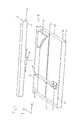
- the support 10 comprises a frame 12 which has a rectangular basic shape.
- L recesses or cuts 16 are provided at regular intervals in the longitudinal direction thereof, which serve as brackets for support 18, wherein the carrier 18 each mounted with their opposite end portions 20 in the recesses 16 and thereby from the frame 12 can be kept.
- FIG. 1 For the sake of clarity, only one carrier 18 is shown. The points in the longitudinal direction L indicate that further such carriers 18 are present.
- one or more cross members 22 extending in the longitudinal direction L can also be provided, on which the carriers 18 also rest.
- the cross beams 22 are connected to the other pair of opposite sides 15 of the frame 12.
- Frame 12, support 18 and cross member 22 are preferably made of steel.
- each support 18 Q support elements 24 are attached at regular intervals in the transverse direction.
- FIG. 1 For the sake of clarity, only two support elements 24 are shown. The points in the transverse direction Q indicate that further support elements 24 may be present. Furthermore, in FIG. 1 a part of a material plate 26 is shown, which rests on the support members 24, which in FIG. 1 but for the sake of clarity is not shown.
- a distance d from each other which is preferably at least 3.5 cm.
- FIG. 1 shows a support 10 which is used in a laser cutting device for cutting metal plates. Shown is also a part 28 of an XY or LQ adjustment of the laser cutting device. As in FIG. 1 is indicated by two arrows, the part 28 is formed movable in the transverse direction Q. At a jet exit portion 30 of the laser cutting device in the longitudinal direction L is arranged movable, which in FIG. 1 again indicated by two arrows. In this way, the beam exit section 30 can be positioned as desired in a plane parallel to the plane defined by the frame 12, that is to say in the longitudinal direction L and in the transverse direction Q. From the beam exit section 30, a laser beam can emerge toward the material plate 26 to cut these.
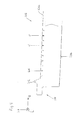
- FIG. 2 Shown is only one of the two end portions 20 of the carrier 18. Both end portions 20 each have a hook 21, with which the carrier 18 can be mounted in recesses 16 of the frame 12 ,
- the Aufsteckverianaschiana 36 allow the attachment of support members 24 on the support 18 by inserting the support members 24 in the Aufsteckverianasch. This will be discussed in more detail below.
- FIG. 3 a support member 24 of the pad 10 according to the invention is shown.
- the support elements 24 are manufactured as separate components, that is, neither with each other nor with the carrier 18 integrally connected.
- the support elements 24 are plate-shaped, wherein the plane of the plate extends in the intended use orientation orthogonal to the transverse direction Q.
- the support member 24 comprises a substantially rectangular portion 24a and one integrally connected thereto triangular portion 24b.
- the tip of the triangular portion 24b is formed flattened to form on a support portion 40 a support surface 24c for material plates 26.
- a plug-in recess 24d is formed in the rectangular section 24a of the support element 24, the dimensions of which are selected such that together with a plug-on depression 36 of the support 18, a stable plug-in connection results.
- the support elements 24 are made of copper or other soft material at least in a portion comprising the support surface 24c for material plates 26, but preferably completely, so that the surfaces of the material plates 26 are not scratched or otherwise damaged. This is particularly advantageous in the case of material plates made of soft metals such as aluminum sheets.
- FIG. 4 shows a part of a second embodiment of a carrier of the pad according to the invention.
- This embodiment corresponds in many parts to the first embodiment of the carrier 18 (see FIG. 2 ).
- analog parts are provided with the same reference numerals as in the FIGS. 1 and 2 , but increased by the number 100.
- the embodiment according to FIG. 4 in the following will be described only insofar as they differ from the embodiment according to FIG. 2 otherwise, reference is hereby made to the description.
- Both end portions 120 extend substantially in the transverse direction (Q) and are insertable into recesses 116 of the frame 112, so that the carrier 118 can be held by the end portions 120 of the frame 112.
- the second embodiment of the carrier 118 differs from the first embodiment of the carrier 18 (see FIG. 2 ) in particular in that an upper boundary surface 118a between all pairs of adjacent Aufsteckveriana 136 is formed free of depressions.
- the carrier 118 thus has no contact with the depressions 32 (FIG. FIG. 2 ) analog recesses.
- the respective end portion 120 in the transverse direction (Q) immediately adjacent, between this end portion 120 and the upper boundary surface 118a a support elevation 142 is provided, in the supporting direction (H) both with respect to the end portions 120 and with respect to upper boundary surface 118a is formed increased.
- the support elevations 142 are provided to support adjacent material plates 26. The upper edge of each support elevation 142 therefore lies in the same plane as the support surfaces 24c of the support elements 24, so that the support elevations 142 and the support elements 24 terminate at the same height in the support direction (H).
Landscapes
- Engineering & Computer Science (AREA)
- Physics & Mathematics (AREA)
- Mechanical Engineering (AREA)
- Optics & Photonics (AREA)
- Plasma & Fusion (AREA)
- Laser Beam Processing (AREA)
Abstract
Description
Die Erfindung betrifft eine Auflage für eine Werkstoffplatte, umfassend einen Rahmen mit einer Mehrzahl von Trägern und einer Mehrzahl von Stützelementen auf jedem Träger, wobei die Stützelemente Auflageabschnitte aufweisen, die bei Aufliegen von Werkstoffplatten auf der Auflage in einer Stützrichtung unmittelbar an den Werkstoffplatten anliegen.The invention relates to a support for a material plate, comprising a frame with a plurality of carriers and a plurality of support elements on each support, wherein the support elements have support portions which bear when resting material plates on the support in a support direction directly to the material plates.
Obwohl die Erfindung im Folgenden hauptsächlich am Beispiel einer Auflage einer Laser-Schneidvorrichtung erläutert werden wird, sei bereits an dieser Stelle darauf hingewiesen, dass die Erfindung mit Vorteil auch bei anderen Arten von Vorrichtungen eingesetzt werden kann, die zur Bearbeitung ebener Werkstücke verwendet werden. Im Bereich der zum Schneiden von Werkstoffplatten vorgesehenen Vorrichtungen kann die Erfindung grundsätzlich beispielsweise auch in Plasma-Schneidvorrichtungen und Brenn-Schneidvorrichtung zum Einsatz kommen.Although the invention will be explained below mainly using the example of a support of a laser cutting device, it should already be pointed out at this point that the invention can be used with advantage also in other types of devices which are used for machining planar workpieces. In the area of devices provided for cutting material plates, the invention can in principle also be used, for example, in plasma cutting devices and internal cutting devices.
Auflagen der eingangs genannten Art sind aus dem Stand der Technik bereits bekannt. Sie dienen als Auflagen für Werkstoffplatten in Vorrichtungen zur Bearbeitung von Werkstoffplatten. Solche Auflagen kommen zum Beispiel in den Laser-Schneidvorrichtungen Trumatic L 2530 und L 3030 der Firma Trumpf zur Anwendung. Diese Vorrichtungen werden zum Schneiden von Metallplatten verwendet und umfassen horizontal ausgerichtete Flachbett-Auflagen, die einen Rahmen, eine Mehrzahl von in diesem Rahmen gehaltenen Trägern sowie Stützelemente, die einstückig mit den Trägern verbunden sind, umfassen. Die Stützelemente weisen Auflageabschnitte auf, die üblicherweise alle in derselben horizontalen Ebene liegen und auf denen die Werkstoffplatten zur Bearbeitung unmittelbar aufliegen können. Die Stützelemente sind in einer Querrichtung der Träger periodisch entlang der Träger angeordnet, wobei jeweils benachbarte Stützelemente gleichen Abstand voneinander aufweisen. Die zwischen benachbarten Stützelementen liegenden Abschnitte der Träger sind als Vertiefungen ausgebildet, in denen sich während der Bearbeitung der Werkstoffplatten Werkstoffpartikel unterschiedlicher Größe in fester oder flüssiger Form sammeln und absetzen können, die bei der Bearbeitung von der Werkstoffplatte abgetragen worden sind. Das Entfernen solcher Ablagerungen kann umständlich beziehungsweise nicht möglich sein. Während der Nutzungsdauer von Trägern und Stützelemente nehmen die Ablagerungen und die damit verbundenen Beeinträchtigungen des ordnungsgemäßen Betriebs der Werkstoffbearbeitungsvorrichtung zu.Editions of the type mentioned are already known from the prior art. They serve as supports for material plates in devices for processing material plates. Such requirements are used, for example, in the laser cutting devices Trumatic L 2530 and L 3030 from Trumpf. These devices are used to cut metal plates and include horizontally oriented flatbed supports comprising a frame, a plurality of carriers held therein, and support members integrally connected to the carriers. The support elements have support portions, which are usually all in the same horizontal plane and on which the material plates can rest directly for processing. The support elements are arranged in a transverse direction of the carrier periodically along the carrier, wherein each adjacent support elements are the same Distance from each other. The lying between adjacent support members portions of the carrier are formed as depressions in which material particles of different sizes in solid or liquid form can accumulate and settle during processing of the material plates, which have been removed during processing of the material plate. The removal of such deposits can be cumbersome or not possible. During the useful life of beams and support members, the deposits and associated impairments to the proper operation of the material handling apparatus increase.
Die bekannten Auflagen sind aus Stahl gefertigt, um über eine ausreichende Stabilität zu verfügen, welche ein Durchhängen der Werkstoffplatte verhindert und deren Planarität während der Bearbeitung sicherstellt. Es hat sich jedoch in der Praxis gezeigt, dass die Werkstoffplatten durch den Kontakt mit den Stützelementen leicht verkratzt werden oder andere Zeichen mechanischer Einwirkung aufweisen können. Dieses Problem tritt beispielsweise bei Aluminiumblechen und Edelstahlblechen in besonderem Maße auf.The known supports are made of steel in order to have sufficient stability, which prevents sagging of the material plate and ensures their planarity during processing. However, it has been shown in practice that the material plates are easily scratched by the contact with the support elements or may have other signs of mechanical action. This problem occurs, for example, in aluminum sheets and stainless steel sheets in particular.
Es ist daher Aufgabe der Erfindung, eine Auflage der eingangs genannten Art anzugeben, bei der derartige Beschädigungen an den aufliegenden Werkstoffplatten nicht oder zumindest nur in vermindertem Maße auftreten.It is therefore an object of the invention to provide a support of the type mentioned, in which such damage to the overlying material plates not or at least occur only to a reduced extent.
Diese Aufgabe wird erfindungsgemäß durch eine Auflage der eingangs genannten Art gelöst, bei welcher die Stützelemente aus einem Material sind, das weicher ist als das Material der Träger. Auf diese Weise können insbesondere bezüglich der Stabilität der Auflage vorteilhafte Materialeigenschaften eines steifen, für die Träger zu bevorzugenden Materials, wie etwa eines Stahls, mit für die Auflageabschnitte bzw. Stützelemente vorteilhaften Eigenschaften eines weicheren Materials, wie etwa Kupfer, kombiniert werden.This object is achieved by a support of the type mentioned, in which the support elements are made of a material that is softer than the material of the carrier. In this way, in particular with regard to the stability of the support advantageous material properties of a stiff, preferable for the carrier material, such as a steel, with advantageous for the support portions or support elements properties of a softer material, such as copper combined.
Die bekannten Auflagen haben Auflageabschnitte, die scharfe rechte Winkel bildende Kanten aufweisen. Es hat sich gezeigt, dass die Werkstoffplatten durch den Kontakt mit diesen Kanten leicht verkratzt werden oder andere Zeichen mechanischer Einwirkung erhalten können. In Weiterbildung der Erfindung wird daher vorgeschlagen, dass die Auflageabschnitte als abgeflachte Spitzen ausgebildet sein können. Auf diese Weise können Beschädigungen von Plattenoberflächen durch unstetige Oberflächenverläufe weiter reduziert werden.The known editions have support sections, the sharp right angles have forming edges. It has been found that the material plates are easily scratched by contact with these edges or can receive other signs of mechanical action. In a further development of the invention, it is therefore proposed that the support sections can be formed as flattened tips. In this way damage to plate surfaces can be further reduced by unsteady surface courses.
Die Plattenoberfläche kann im Bearbeitungsprozess nicht nur durch eine mechanische Einwirkung der Auflage, sondern auch durch Anlagerung von abgetrennten Werkstoffpartikein, wie zum Beispiel Metallspritzern, beeinträchtigt werden. Ein weiterer Vorteil von als abgeflachte Spitzen ausgebildeten Auflageabschnitte liegt darin, dass die Verschmutzung von aufliegenden Werkstoffplatten durch bei der Bearbeitung abgetragene Werkstoffpartikel dadurch verringert werden kann, dass die Auflageabschnitte erfindungsgemäß im Vergleich zu den bekannten Auflageflächen als Spitze verkleinert ausgebildet sind, so dass sich weniger Werkstoffpartikel an den Auflageabschnitten sammeln und von diesen auf die Platten gelangen können.The plate surface can be affected in the machining process not only by a mechanical action of the support, but also by addition of separated Materialpartikein, such as metal splash. A further advantage of support sections formed as flattened tips is that the contamination of overlying material plates can be reduced by material particles removed during processing in that, according to the invention, the support sections are made smaller in size than the known support surfaces so that fewer material particles are formed Collect on the support sections and can get from these on the plates.
Es wird ferner vorgeschlagen, dass zumindest die Auflageabschnitte der Stützelemente, vorzugsweise die Stützelemente insgesamt, aus Kupfer gefertigt sein können. Es wurde vorstehend bereits erwähnt, dass Kupfer aufgrund seiner Weichheit besonders wenige Beschädigungen bzw. sonstige mechanische Spuren an den aufliegenden Werkstoffplatten hervorruft, und dies selbst dann, wenn die Werkstoffplatten Aluminiumbleche sind. Ein weiterer Vorteil, der durch den Einsatz von aus Kupfer gefertigten Stützelementen erzielt werden kann, besteht darin, dass solche Stützelemente mit relativ geringem Zeit- und Kostenaufwand durch Stanzen hergestellt werden können. Beim Einsatz der Auflage in einer Laser-Schneidvorrichtung mit einem Kohlendioxid-Laser kann ferner eine möglicherweise gefährdend oder destabilisierend wirkende Erhitzung der Auflageabschnitte vermieden werden, da Kupfer elektromagnetische Strahlung im Wellenlängenbereich von Kohlendioxid-Lasern im Wesentlichen reflektiert. Grundsätzlich eignen sich in dieser Hinsicht auch andere Materialien, die ein ähnliches Reflexionsvermögen aufweisen, beispielsweise Aluminium, Zink, Silber und Gold.It is further proposed that at least the support sections of the support elements, preferably the support elements in total, can be made of copper. It has already been mentioned above that copper, because of its softness, causes very little damage or other mechanical traces on the resting material plates, and this even if the material plates are aluminum plates. Another advantage that can be achieved by the use of copper-made support elements, is that such support elements can be produced with relatively little time and cost by punching. When using the support in a laser cutting device with a carbon dioxide laser can also be a potentially hazardous or destabilizing acting heating of the support sections are avoided because copper electromagnetic radiation in the wavelength range of carbon dioxide lasers essentially reflected. In principle, other materials which have a similar reflectivity, for example aluminum, zinc, silver and gold, are also suitable in this regard.
In Weiterbildung der Erfindung wird vorgeschlagen, dass die Stützelemente im Wesentlichen plattenförmig ausgebildet sein können, wobei die Plattenebene in dem auf dem zugeordneten Träger angeordneten Zustand zur Querrichtung dieses Trägers im Wesentlichen orthogonal verlaufen kann. Hierdurch kann erreicht werden, dass die Stützelemente mit geringem Zeit-und Kostenaufwand aus Blech gestanzt werden können. Grundsätzlich sind jedoch beliebig geformte Stützelemente denkbar, beispielsweise im Wesentlichen stabförmige oder im Wesentlichen kegelförmige Stützelemente.In a further development of the invention, it is proposed that the support elements can be formed substantially plate-shaped, wherein the plate plane in the arranged on the associated carrier state to the transverse direction of this carrier can be substantially orthogonal. This can achieve that the support elements can be stamped with little time and cost from sheet metal. In principle, however, any shaped support elements are conceivable, for example, substantially rod-shaped or substantially conical support elements.
Ferner wird vorgeschlagen, dass Träger und Stützelemente als gesonderte Bauteile ausgebildet sein können. Auf diese Weise brauchen die Träger dann, wenn ein Auswechseln von Stützelementen erforderlich wird, nicht, wie bei den bekannten einstückig mit den Stützelementen ausgebildeten Trägern, ebenfalls ausgewechselt zu werden. Und umgekehrt können bei Austausch eines Trägers die darauf angeordneten Stützelemente weiterverwendet werden. Dies ermöglicht eine Verringerung der Betriebskosten.It is also proposed that the carrier and supporting elements can be designed as separate components. In this way, when an exchange of support members is required, the supports need not be replaced, as in the known integrally formed with the support members carriers. And conversely, when replacing a carrier, the support elements arranged thereon can continue to be used. This allows a reduction in operating costs.
Ferner wird vorgeschlagen, dass die Stützelemente in dem auf dem zugeordneten Träger angeordneten Zustand relativ zu diesem Träger höchstens in Stützrichtung beweglich sein können. Hierdurch kann gewährleistet werden, dass Werkstoffplatten stabil und ohne Relativbewegung zu den Trägern auf diesen aufliegen und dadurch fehler- und beschädigungsfrei bearbeitet werden können.It is also proposed that the support elements in the state arranged on the associated carrier can be movable relative to this carrier at most in the supporting direction. In this way it can be ensured that material plates rest stable and without relative movement to the carriers on these and thus can be processed without errors and damage.
Wie vorstehend bereits erwähnt können die Auflageabschnitte, vorzugsweise alle Auflageabschnitte, in ein und derselben Auflageabschnitte-Ebene liegen. Dadurch kann zum Beispiel eine ebene Werkstoffplatte bei horizontaler Ausrichtung der Auflageabschnitte-Ebene ohne zusätzliche Haltevorrichtung für die Werkstoffplatte gelagert werden. Die Erfindung ist jedoch auf Auflagen mit räumlich beliebig ausgerichteter Rahmen-Ebene gerichtet. Denkbar sind auch Auflagen, die Vorrichtungen zum Befestigen von Werkstoffplatten vorsehen. Denkbar ist ebenfalls eine Ausführungsform, in der nicht alle Auflageabschnitte in derselben Ebene liegen, sowie eine Ausführungsform, in der Stützelemente um einen Betrag in Stützrichtung bewegt werden können, der für jedes derart bewegbare Stützelement individuell bestimmt und eingestellt werden kann. Eine solche Ausführungsform ist zum Beispiel denkbar für den Einsatz zur Bearbeitung von Werkstoffplatten inhomogener Flächenmasseverteilung. Um ein ebenes Anliegen einer solchen Platte zu erzielen, kann es je nach Art der Stützelemente erforderlich sein, die Auflageabschnitte nach Herstellen des Anlage-Zustands einzeln in Stützrichtung neu zu positionieren. Eine solche Ausführungsform ist auch für die Bearbeitung von Werkstoffplatten unterschiedlicher Dicke denkbar.As already mentioned above, the support sections, preferably all the support sections, can lie in one and the same support section plane. As a result, for example, a flat material plate with horizontal orientation of the support sections-level without additional holding device be stored for the material plate. However, the invention is directed to conditions with spatially arbitrarily aligned frame level. Also conceivable are pads that provide devices for attaching material plates. Also conceivable is an embodiment in which not all the support sections lie in the same plane, as well as an embodiment in which the support elements can be moved by an amount in the direction of support, which can be individually determined and adjusted for each such movable support element. Such an embodiment is conceivable, for example, for use in processing material plates of inhomogeneous basis weight distribution. In order to achieve a level concern of such a plate, it may be necessary, depending on the nature of the support elements, to reposition the support sections individually after production of the installation state in the direction of support. Such an embodiment is also conceivable for the processing of material plates of different thickness.
Um ein schnelles und einfaches Austauschen von Stützelementen ohne Hilfsmittel zu ermöglichen, ist es vorteilhaft, wenn die Stützelemente auf den jeweils zugeordneten Träger aufsteckbar ausgebildet sind. Die bekannten Träger sind von der Seite, an der die Werkstoffplatten anliegen, also in Stützrichtung, am besten zugänglich, so dass das Aufstecken der Stützelemente vorzugsweise in Stützrichtung möglich sein kann.In order to enable a quick and easy replacement of support elements without aids, it is advantageous if the support elements are designed to be plugged onto the respective associated carrier. The known carriers are best accessible from the side against which the material plates, ie in the direction of support, so that the attachment of the support elements may preferably be possible in the direction of support.
In Weiterbildung der Erfindung wird vorgeschlagen, dass sowohl das Stützelement als auch der Träger eine Aufsteckvertiefung aufweisen können, wobei Stützelement und Träger beim Aufstecken wechselseitig nach Art der Blockhaus-Bauweise in die Aufsteckvertiefung des jeweils anderen Teils einführbar sind. Diese Ausführung der Steckverbindung gewährleistet ein stabiles Anliegen von Platten an der Auflage dadurch, dass zum einen seitliche Begrenzungsflächen der Stützelemente sich an dem Träger, auf dem sie angeordnet sind, in einer ersten Richtung abstützen können, die zur Aufsteckrichtung im Wesentlichen orthogonal verläuft, und zum anderen Begrenzungsflächen des Trägers sich an den auf dem Träger angeordneten Stützelementen in einer zweiten Richtung abstützen können, die sowohl zur Aufsteckrichtung als auch zur ersten Richtung im Wesentlichen orthogonal verläuft, so dass die Stützelemente unter dem Druck der aufliegenden Werkstoffplatte nicht wegkippen können. Darüber hinaus kann durch eine Steckverbindung nach Art der Blockhaus-Bauweise auch verhindert werden, dass die Stützelemente sich unter dem Druck der aufliegenden Werkstoffplatte weiter in Aufsteckrichtung bewegen.In a further development of the invention, it is proposed that both the support element and the carrier can have a Aufsteckvertiefung, support member and support when plugging each other in the manner of the block house construction in the Aufsteckvertiefung the other part are inserted. This version of the connector ensures a stable concern of plates on the support in that on the one hand lateral boundary surfaces of the support elements can be supported on the support on which they are arranged in a first direction, which extends to the direction of attachment substantially orthogonal, and other boundary surfaces of the carrier are arranged on the on the carrier Supporting elements can support in a second direction, which is substantially orthogonal both to Aufsteckrichtung and to the first direction, so that the support elements under the pressure of the overlying material plate can not tip over. In addition, it can also be prevented by a connector according to the type of log cabin construction that the support elements move under the pressure of the overlying material plate further in Aufsteckrichtung.
Weiterhin ist es vorteilhaft, wenn benachbarte Stützelemente in einer zur Stützrichtung orthogonal verlaufenden Richtung einen vorbestimmten Mindestabstand voneinander aufweisen, der vorzugsweise wenigstens 1 cm, noch bevorzugter wenigstens 2 cm, beträgt. Damit kann erreicht werden, dass sich abgetragene Werkstoffpartikel bevorzugt zwischen den Stützelementen statt an bzw. auf diesen ablagern, so dass die Nutzungsdauer der Stützelemente verlängert werden kann. Ein weiterer Vorteil eines solchen Mindestabstands ist, dass dadurch die Zahl der verwendeten Stützelemente und damit die Materialkosten beschränkt werden.Furthermore, it is advantageous if adjacent support elements in a direction orthogonal to the support direction have a predetermined minimum distance from one another, which is preferably at least 1 cm, more preferably at least 2 cm. It can thus be achieved that ablated material particles preferably deposit between the support elements instead of or on these, so that the useful life of the support elements can be extended. Another advantage of such a minimum distance is that thereby the number of supporting elements used and thus the material costs are limited.
Um die Verschmutzung der Stützelemente und insbesondere der Auflageabschnitte reduzieren zu können, ist es ferner vorteilhaft, wenn die Stützelemente sich zu den Auflageabschnitten hin verjüngend ausgebildet sind. Hierdurch können in flüssiger Form an die Auflageabschnitte gelangte Werkstoffe besser abperlen und feste Werkstoffpartikel leichter von den Auflageabschnitten abrutschen.In order to reduce the contamination of the support elements and in particular of the support sections, it is also advantageous if the support elements are tapered to the support sections. As a result, in liquid form to the support sections reached materials better bead and solid material particles easily slip off the support sections.
Es ist weiterhin von Vorteil, wenn die Auflageabschnitte der Stützelemente von einer oberen Begrenzungsfläche des jeweils zugeordneten Trägers in Stützrichtung einen vorbestimmten Mindestabstand aufweisen. Dadurch kann erreicht werden, dass die Anzahl der von der Auflage an eine anliegende Platte zurückspringenden Werkstoffpartikel reduziert wird, so dass Platten bei der Bearbeitung weniger verschmutzt werden.It is furthermore advantageous if the support sections of the support elements have a predetermined minimum distance from an upper boundary surface of the respective associated carrier in the direction of support. As a result, it can be achieved that the number of material particles rebounding from the support to an abutting plate is reduced, so that plates are less contaminated during processing.
Die Auflageabschnitte der bekannten Stützelemente weisen in Stützrichtung keinen Abstand von einer oberen Begrenzungsfläche des jeweils zugeordneten Trägers auf, da diese Auflageabschnitte in derselben zur Stützrichtung orthogonal ausgerichteten Ebene liegen wie die obere Begrenzungsfläche des jeweils zugeordneten Trägers. Die Auflageabschnitte sind in der vorliegenden Erfindung demgegenüber erhöht ausgebildet, so dass die Stützelemente weniger verschmutzen, da mehr Raum für von den Stützelementen herabperlende bzw. -rutschende Werkstoffpartikel in den Vertiefungen bereitsteht. Somit dauert es länger, bis die Vertiefungen so verschmutzt sind, dass dieser Sammelungsmechanismus nicht mehr funktioniert.The support sections of the known support elements have in the direction of support no distance from an upper boundary surface of the respective associated carrier, since these support sections lie in the same direction orthogonally oriented to the support plane as the upper boundary surface of the respective associated carrier. By contrast, in the present invention, the support sections are designed to be increased so that the support elements become less polluted, since more space is available for material particles that project or slip down from the support elements in the recesses. Thus, it takes longer for the wells to be so dirty that this collection mechanism no longer works.
Weiterhin wird durch den Mindestabstand die Anzahl der von der Auflage an ein Stützelement zurückgeworfenen Werkstoffpartikel reduziert, so dass die Nutzungsdauer der Stützelemente verlängert werden kann.Furthermore, the minimum distance reduces the number of material particles thrown back from the support to a support element, so that the service life of the support elements can be extended.
Ferner ist es vorteilhaft, wenn die Träger mit in ihrer jeweiligen Querrichtung, vorzugsweise periodisch, angeordneten Vertiefungen ausgebildet sind. Hierdurch kann erreicht werden, dass sich abgetragene Werkstoffpartikel in den Vertiefungen statt an den Auflageabschnitten sammeln können, so dass die Auflageabschnitte nicht verunreinigt werden. Die Vertiefungen sind vorzugsweise zwischen den Positionen, an denen die Stützelemente angeordnet sind, ausgebildet. Sie sind darüber hinaus vorzugsweise in einer oder von einer oberen Begrenzungsfläche der Träger ausgehend ausgebildet.Furthermore, it is advantageous if the carriers are formed with depressions arranged in their respective transverse direction, preferably periodically. In this way, it can be achieved that eroded material particles can collect in the recesses instead of on the support sections, so that the support sections are not contaminated. The recesses are preferably formed between the positions at which the support elements are arranged. In addition, they are preferably formed starting in or from an upper boundary surface of the carrier.
Damit die Träger von dem Rahmen der Auflage gehalten werden können, kann der Rahmen für jeden Träger Halterungen aufweisen, mit denen Endabschnitte der Träger in Eingriff bringbar sind.In order for the supports to be supported by the frame of the support, the frame for each support may have brackets with which end portions of the supports are engageable.
Ferner kann die Auflage eine Auflage einer Vorrichtung zur Werkstoffbearbeitung sein, insbesondere eine Auflage einer Vorrichtung zum Schneiden von Werkstoffplatten. Diese Vorrichtung kann beispielsweise eine Laser-Schneidvorrichtung sein. Grundsätzlich sind aber auch Plasma- oder Brenn-Schneidvorrichtungen denkbar. In Weiterbildung dessen kann die Vorrichtung zur Werkstoffbearbeitung zum Bearbeiten von Metallplatten konfiguriert sein.Furthermore, the support may be a support of a device for material processing, in particular a support of a device for cutting material plates. This device may for example be a laser cutting device. In principle, however, plasma or flame cutting devices conceivable. In a further development, the device for material processing can be configured for processing metal plates.
Die Erfindung wird im Folgenden an einem Ausführungsbeispiel anhand der beigefügten Zeichnungen näher erläutert werden. Es zeigt:
- Figur 1
- eine schematische Ansicht der erfindungsgemäßen Auflage und eines Teils einer Laserführungsvorrichtung der erfindungsgemäßen Auflage;
- Figur 2
- in Seitenansicht einen Teil einer ersten Ausführungsform eines Trägers der erfindungsgemäßen Auflage;
- Figur 3
- ein Stützelement der erfindungsgemäßen Auflage;
- Figur 4
- in Seitenansicht einen Teil einer zweiten Ausführungsform eines Trägers der erfindungsgemäßen Auflage;
- FIG. 1
- a schematic view of the support according to the invention and a part of a laser guiding device of the support according to the invention;
- FIG. 2
- in side view part of a first embodiment of a support of the support according to the invention;
- FIG. 3
- a support element of the support according to the invention;
- FIG. 4
- in side view part of a second embodiment of a support of the support according to the invention;
In
Falls der Abstand zwischen den Seiten 14 des Rahmens 12 zu groß ist, können ferner ein oder mehrere sich in Längsrichtung L erstreckende Querträger 22 vorgesehen sein, auf denen die Träger 18 ebenfalls aufliegen. Die Querträger 22 sind mit dem anderen Paar gegenüberliegender Seiten 15 des Rahmens 12 verbunden. Rahmen 12, Träger 18 und Querträger 22 sind vorzugsweise aus Stahl gefertigt.If the distance between the
Auf jedem Träger 18 sind in regelmäßigen Abständen in Querrichtung Q Stützelemente 24 aufgesteckt. In
Von einer oberen Begrenzungsfläche 18a des Trägers 18 gehen Vertiefungen 32 aus, die in Querrichtung Q des Trägers 18 in regelmäßigen Abständen zwischen dessen beiden Endabschnitten 20 vorgesehen sind. Zwischen jedem Paar benachbarter Vertiefungen 32 ist ein Aufsteckabschnitt 34 mit einer Aufsteckvertiefung 36 und dieser benachbarten Auflageflächen 38 vorgesehen. Die Auflageflächen 38 sind Teil der oberen Begrenzungsfläche 18a des Trägers 18.From an upper boundary surface 18a of the
Die Aufsteckvertiefungen 36 ermöglichen das Aufstecken von Stützelementen 24 auf den Träger 18 durch Einführen der Stützelemente 24 in die Aufsteckvertiefungen 36. Hierauf wird weiter unten noch näher eingegangen werden.The
In
Beim Aufstecken eines Stützelements 24 auf den Träger 18 greifen die beiden Aufsteckvertiefung 24d und 36 nach Art der Blockhaus-Bauweise ineinander, d.h. derart, dass die stirnseitige Begrenzungsfläche E der Aufsteckvertiefung 24d an der stirnseitigen Begrenzungsfläche E' (siehe
Die Stützelemente 24 sind zumindest in einem die Auflagefläche 24c für Werkstoffplatten 26 umfassenden Abschnitt, vorzugsweise aber vollständig, aus Kupfer oder einem anderen weichen Material gefertigt, so dass die Oberflächen der Werkstoffplatten 26 nicht zerkratzt oder anderweitig beschädigt werden. Dies ist insbesondere bei aus weichen Metallen bestehenden Werkstoffplatten wie Aluminiumblechen vorteilhaft.The
Gemäß einem praktischen Ausführungsbeispiel können der Träger 18 und die Stützelemente 24 die folgenden Abmessungen aufweisen:
- Die Länge des Trägers 18 in Querrichtung Q beträgt 1640 mm.
- Die größte Höhe des
Trägers 18 in Höhenrichtung H, die dem Abstand zwischen der oberen Begrenzungsfläche 18a und einer zu dieser parallelen unteren Begrenzungsfläche 18b desTrägers 18 entspricht, beträgt 82,79 mm.
- The length of the
carrier 18 in the transverse direction Q is 1640 mm. - The maximum height of the
carrier 18 in the height direction H, which corresponds to the distance between the upper boundary surface 18a and a parallel to this lower boundary surface 18b of thecarrier 18, is 82.79 mm.
Die Träger 18 sind also im Wesentlichen als schmale lange Platten ausgebildet und haben in Längsrichtung L ihre kleinste Breite und in Querrichtung Q ihre größte Länge.
- Der kleinste Abstand der Innenflächen A und
B der Aufsteckvertiefung 24d des Stützelements 24 beträgt 2,5 mm. - Die Länge der in Höhenrichtung H verlaufenden Kanten des rechteckigen Abschnitts 24a des Stützelements 24
beträgt 20,81 mm. - Die Länge der in Längsrichtung L verlaufenden Kanten des rechteckigen Abschnitts 24a des Stützelements 24
beträgt 15 mm. - Die Höhe des Stützelements 24 in Höhenrichtung H beträgt 32,81 mm.
Die Auflageabschnitte 40der Stützelemente 24 weisen von der oberen Begrenzungsfläche 18a desTrägers 18, auf dem sie angeordnet sind, in Stützrichtung (Höhenrichtung H) einen Abstand von mindestens 1,3 cm auf.- Der kleinste Abstand der Innenflächen C' und D' der Aufsteckvertiefung 36 des
Trägers 18 beträgt 2,5 mm. - Die
Tiefe der Aufsteckvertiefungen 36 desTrägers 18 beträgt 6 mm. - Der Abstand von einander entsprechenden Innenflächen (zum Beispiel der Innenflächen D') benachbarter Aufsteckvertiefungen 36
beträgt 38 mm. - Die größte Breite der Vertiefungen 32 und der kleinste Abstand der Auflageflächen 38
benachbarter Aufsteckabschnitte 34 betragen jeweils 20,21 mm.
- The smallest distance of the inner surfaces A and B of the
Aufsteckvertiefung 24d of thesupport member 24 is 2.5 mm. - The length of the edges H in the height direction of the
rectangular portion 24a of thesupport member 24 is 20.81 mm. - The length of the longitudinally extending L edges of the
rectangular portion 24a of thesupport member 24 is 15 mm. - The height of the
support element 24 in height direction H is 32.81 mm. - The
support portions 40 of thesupport members 24 have from the upper boundary surface 18 a of thesupport 18, on which they are arranged, in the support direction (height direction H) at a distance of at least 1.3 cm. - The smallest distance of the inner surfaces C 'and D' of the
Aufsteckvertiefung 36 of thesupport 18 is 2.5 mm. - The depth of the
Aufsteckvertiefungen 36 of thesupport 18 is 6 mm. - The distance from corresponding inner surfaces (for example, the inner surfaces D ') of
adjacent Aufsteckvertiefungen 36 is 38 mm. - The largest width of the
recesses 32 and the smallest distance of the bearing surfaces 38adjacent Aufsteckabschnitte 34 are each 20.21 mm.
Dargestellt ist lediglich einer der beiden Endabschnitte 120 des Trägers 118. Beide Endabschnitte 120 erstrecken sich im Wesentlichen in Querrichtung (Q) und sind in Ausnehmungen 116 des Rahmens 112 einführbar, so dass der Träger 118 durch die Endabschnitte 120 von dem Rahmen 112 gehalten werden kann.Shown is merely one of the two
Die zweite Ausführungsform des Träger 118 unterscheidet sich von der ersten Ausführungsform des Trägers 18 (siehe
Gemäß einem praktischen Ausführungsbeispiel kann der Träger 118 die folgenden Abmessungen aufweisen:
- Die
Länge der Träger 118 in Querrichtung Q beträgt 1365 mm. - Die größte Höhe der
Träger 118 in Höhenrichtung H, die wegen derAuflageerhöhung 142 größer als der Abstand zwischen der oberen Begrenzungsfläche 118a und einer zu dieser parallelen unteren Begrenzungsfläche 118b desTrägers 118 ist, beträgt 82,35 mm. - Der kleinste Abstand zwischen einer
den Endabschnitt 120 in Stützrichtung H nach oben begrenzenden Kante desEndabschnitts 120 und der unteren Begrenzungsfläche 118b desTrägers 118beträgt 74,15 mm. - Der kleinste Abstand zwischen einer
den Endabschnitt 120 in Stützrichtung H nach unten begrenzenden Kante desEndabschnitts 120 und der unteren Begrenzungsfläche 118b desTrägers 118 beträgt 57,48 mm. - Der kleinste Abstand von Innenflächen C' und D' der
Aufsteckvertiefung 136 desTrägers 118 beträgt 2,5 mm. - Der Abstand von einander entsprechenden Innenflächen (zum Beispiel der Innenflächen D') benachbarter Aufsteckvertiefungen 136
beträgt 16 mm. DerAbschnitt des Trägers 118 zwischen zwei benachbarten Aufsteckvertiefungen 136 weist in Längsrichtung L desTrägers 118 eine Länge von 13,5 mm auf. - Die
Tiefe der Aufsteckvertiefungen 136 desTrägers 118 beträgt 6 mm. - In
den Trägern 118 sind in Stützrichtung H von der unteren Begrenzungsfläche 118b ausgehende, inFigur 4 nicht dargestellte Vertiefungen vorgesehen, mit denen dieTräger 118 auf Querträgern 122 aufliegen. Die Breite dieser Vertiefungen in Querrichtung (Q) beträgt 6,5 mm, die Tiefe dieser Vertiefungen in Stützrichtung (H) beträgt 25,05 mm.
- The length of the
carriers 118 in the transverse direction Q is 1365 mm. - The maximum height of the
beams 118 in the height direction H, which is greater than the distance between theupper boundary surface 118a and a parallel to thislower boundary surface 118b of thesupport 118 due to thesupport 142, is 82.35 mm. - The smallest distance between an edge of the
end section 120 which delimits theend section 120 in the support direction H upwards and thelower boundary surface 118b of thecarrier 118 is 74.15 mm. - The smallest distance between an
end portion 120 in the direction of support H downwardly bounding edge of theend portion 120 and thelower boundary surface 118b of thecarrier 118 is 57.48 mm. - The smallest distance from inner surfaces C 'and D' of the
Aufsteckvertiefung 136 of thecarrier 118 is 2.5 mm. - The distance from corresponding inner surfaces (for example, the inner surfaces D ') of
adjacent Aufsteckvertiefungen 136 is 16 mm. The section of thecarrier 118 between two adjacent attachment recesses 136 has a length of 13.5 mm in the longitudinal direction L of thecarrier 118. - The depth of the
Aufsteckvertiefungen 136 of thecarrier 118 is 6 mm. - In the
carriers 118 are in the direction H from thelower boundary surface 118b outgoing, inFIG. 4 recesses not shown provided with which thecarrier 118 rest on cross members 122. The width of these recesses in the transverse direction (Q) is 6.5 mm, the depth of these recesses in the direction of support (H) is 25.05 mm.
Claims (15)
dadurch gekennzeichnet, dass die Auflageabschnitte (40) als abgeflachte Spitzen ausgebildet sind.Support (10) according to one of the preceding claims,
characterized in that the support portions (40) are formed as flattened tips.
dadurch gekennzeichnet, dass zumindest die Auflageabschnitte (40) der Stützelemente (24), vorzugsweise die Stützelemente (24) insgesamt, aus Kupfer gefertigt sind.Support (10) according to one of the preceding claims,
characterized in that at least the support portions (40) of the support elements (24), preferably the support elements (24) in total, are made of copper.
dadurch gekennzeichnet, dass die Stützelemente (24) im Wesentlichen plattenförmig ausgebildet sind, wobei die Plattenebene in dem auf dem zugeordneten Träger (18, 118) angeordneten Zustand zur Querrichtung (Q) dieses Trägers (18, 118) im Wesentlichen orthogonal verläuft.Support (10) according to one of the preceding claims,
characterized in that the support elements (24) are formed substantially plate-shaped, wherein the plane of the plate in the on the associated carrier (18, 118) arranged state to the transverse direction (Q) of this support (18, 118) is substantially orthogonal.
dadurch gekennzeichnet, dass Träger (18, 118) und Stützelemente (24) als gesonderte Bauteile ausgebildet sind.Support (10) according to one of the preceding claims,
characterized in that carriers (18, 118) and support elements (24) are formed as separate components.
dadurch gekennzeichnet, dass die Stützelemente (24) in dem auf dem zugeordneten Träger (18, 118) angeordneten Zustand relativ zu diesem Träger (18, 118) höchstens in Stützrichtung (H) beweglich sind.Support (10) according to one of the preceding claims,
characterized in that the support elements (24) in the arranged on the associated carrier (18, 118) state relative to this support (18, 118) at most in the support direction (H) are movable.
dadurch gekennzeichnet, dass die Stützelemente (24) auf den jeweils zugeordneten Träger (18,118) aufsteckbar ausgebildet sind.Support (10) according to one of the preceding claims,
characterized in that the support elements (24) on the respectively associated carrier (18,118) are designed plugged.
dadurch gekennzeichnet, dass sowohl das Stützelement (24) als auch der Träger (18, 118) eine Aufsteckvertiefung (36, 136) aufweisen, wobei Stützelement (24) und Träger (18, 118) beim Aufstecken wechselseitig in die Aufsteckvertiefung (36, 136) des jeweils anderen Teils einführbar sind.Support (10) according to one of the preceding claims,
characterized in that both the support element (24) and the carrier (18, 118) have a Aufsteckvertiefung (36, 136), said support element (24) and support (18, 118) when plugged into each other in the Aufsteckvertiefung (36, 136 ) of the other part are insertable.
dadurch gekennzeichnet, dass benachbarte Stützelemente (24) in einer zur Stützrichtung (H) orthogonal verlaufenden Richtung (Q) einen vorbestimmten Mindestabstand voneinander aufweisen, der vorzugsweise wenigstens 1 cm, noch bevorzugter wenigstens 2 cm, beträgt.Support (10) according to one of the preceding claims,
characterized in that adjacent support elements (24) in a direction orthogonal to the support direction (H) extending direction (Q) have a predetermined minimum distance from each other, which is preferably at least 1 cm, more preferably at least 2 cm.
dadurch gekennzeichnet, dass die Stützelemente (24) sich zu den Auflageabschnitten (40) hin verjüngend ausgebildet sind.Support (10) according to one of the preceding claims,
characterized in that the support elements (24) are tapered to the support portions (40).
dadurch gekennzeichnet, dass die Auflageabschnitte (40) der Stützelemente (24) von einer oberen Begrenzungsfläche (18a, 118a) des jeweils zugeordneten Trägers (18, 118) in Stützrichtung (H) einen vorbestimmten Mindestabstand aufweisen.Support (10) according to one of the preceding claims,
characterized in that the support portions (40) of the support elements (24) from an upper boundary surface (18a, 118a) of the respectively associated carrier (18, 118) in the support direction (H) have a predetermined minimum distance.
dadurch gekennzeichnet, dass die Träger (18, 118) mit in ihrer jeweiligen Querrichtung (Q), vorzugsweise periodisch, angeordneten Vertiefungen (32) ausgebildet sind.Support (10) according to one of the preceding claims,
characterized in that the supports (18, 118) are formed with depressions (32) arranged in their respective transverse direction (Q), preferably periodically.
dadurch gekennzeichnet, dass der Rahmen (12, 112) für jeden Träger (18, 118) Halterungen (16, 116) aufweist, mit denen Endabschnitte (20, 120) der Träger (18, 118) in Eingriff bringbar sind.Support (10) according to one of the preceding claims,
characterized in that the frame (12, 112) for each carrier (18, 118) has holders (16, 116) with which end portions (20, 120) of the carriers (18, 118) are engageable.
dadurch gekennzeichnet, dass sie die Auflage (10) einer Vorrichtung zur Werkstoffbearbeitung ist, insbesondere die Auflage (10) einer Vorrichtung zum Schneiden von Werkstoffplatten (26).Support (10) according to one of the preceding claims,
characterized in that it is the support (10) of a device for material processing, in particular the support (10) of a device for cutting material plates (26).
dadurch gekennzeichnet, dass die Vorrichtung zur Werkstoffbearbeitung zum Bearbeiten von Metallplatten konfiguriert ist.Pad (10) according to claim 14,
characterized in that the device for material processing is configured for processing metal plates.
Applications Claiming Priority (1)
| Application Number | Priority Date | Filing Date | Title |
|---|---|---|---|
| DE102010028606A DE102010028606A1 (en) | 2010-05-05 | 2010-05-05 | Pad for a material plate |
Publications (1)
| Publication Number | Publication Date |
|---|---|
| EP2384846A2 true EP2384846A2 (en) | 2011-11-09 |
Family
ID=44117622
Family Applications (1)
| Application Number | Title | Priority Date | Filing Date |
|---|---|---|---|
| EP11163892A Withdrawn EP2384846A2 (en) | 2010-05-05 | 2011-04-27 | Support for a material board |
Country Status (2)
| Country | Link |
|---|---|
| EP (1) | EP2384846A2 (en) |
| DE (1) | DE102010028606A1 (en) |
Cited By (1)
| Publication number | Priority date | Publication date | Assignee | Title |
|---|---|---|---|---|
| CN108237302A (en) * | 2018-01-31 | 2018-07-03 | 中国电子科技集团公司第三十八研究所 | The Robot Spot Welding tooling and method of a kind of antenna element |
Families Citing this family (1)
| Publication number | Priority date | Publication date | Assignee | Title |
|---|---|---|---|---|
| CN103624431B (en) * | 2012-08-21 | 2015-05-20 | 上海工程技术大学 | Flexible thin plate positioning fixture based on T-type groove |
Family Cites Families (3)
| Publication number | Priority date | Publication date | Assignee | Title |
|---|---|---|---|---|
| AT321688B (en) * | 1973-05-23 | 1975-04-10 | Voest Ag | Flame cutting machine for cutting through metallic workpieces, in particular metallic sheets or plates |
| DE8622740U1 (en) * | 1986-08-25 | 1986-10-09 | Messer Griesheim Gmbh, 6000 Frankfurt | Cutting and / or welding table |
| DE29923647U1 (en) * | 1999-07-27 | 2001-06-28 | Meiko Maschb Gmbh & Co | Underlay for sheet metal |
-
2010
- 2010-05-05 DE DE102010028606A patent/DE102010028606A1/en not_active Withdrawn
-
2011
- 2011-04-27 EP EP11163892A patent/EP2384846A2/en not_active Withdrawn
Non-Patent Citations (1)
| Title |
|---|
| None |
Cited By (1)
| Publication number | Priority date | Publication date | Assignee | Title |
|---|---|---|---|---|
| CN108237302A (en) * | 2018-01-31 | 2018-07-03 | 中国电子科技集团公司第三十八研究所 | The Robot Spot Welding tooling and method of a kind of antenna element |
Also Published As
| Publication number | Publication date |
|---|---|
| DE102010028606A1 (en) | 2011-11-10 |
Similar Documents
| Publication | Publication Date | Title |
|---|---|---|
| DE202008012632U1 (en) | Machining machine for six-sided machining | |
| EP1425142B1 (en) | Device for accommodating flat materials during separation by a separating device, and a separating method | |
| EP2384857A1 (en) | Device for tensioning a workpiece | |
| EP2134519B1 (en) | Device for separating a strand of plastic material, having a carrier supporting a notching device and a cutting device | |
| DE7730033U1 (en) | Machine, especially combined punching and fusion cutting machine | |
| EP3548234B1 (en) | Long knife with several components | |
| EP2384846A2 (en) | Support for a material board | |
| DE2822828B2 (en) | Clamping or holding device for workpieces | |
| DE60114704T2 (en) | blanking press | |
| EP0086954A2 (en) | Tool to extract an electronic drawer from its frame | |
| DE60101431T2 (en) | Positioning device for ceramic objects | |
| DE3242544A1 (en) | HOLDING DEVICE | |
| DE3312746C2 (en) | ||
| DE102011082427A1 (en) | Laser beam processing device comprises non-contact support means for supporting workpiece, laser beam application means, processing supply means for supplying workpiece relative to laser beam application means, and fragment tightening means | |
| DE3203681C2 (en) | Height adjustment device for the upper punch of a stop tool | |
| DE3104667A1 (en) | LOADING DEVICE FOR METAL BLanks | |
| DE102006036193B4 (en) | Device and method for assembling a furniture body | |
| DE102011106469A1 (en) | Strip-shaped workpiece support element useful for forming a workpiece support for thermally cutting material processing device, comprises two longitudinal sides extending two-dimensionally for forming a respective workpiece support area | |
| DE60113507T2 (en) | Process for flame cutting hot or cold slabs without welding | |
| EP3331685A1 (en) | Mounting device | |
| AT505173B1 (en) | DEVICE FOR WORKING WORKPIECES | |
| DE102006050648B3 (en) | Device turning over sheet components between two presses and exchanging gripping tools, includes carriers with arms and clamping mechanisms running on elevated beam | |
| DE102011009622A1 (en) | Supporting device, useful for a laser- or plasma cutting machine, comprises frame, which is designed for holding supporting bars, and provided for arranging laser or plasma cutting machine in changing carriage or fixed table | |
| DE102018003622A1 (en) | Device and method for cutting out a workpiece | |
| DE102022125475A1 (en) | Water jet cutting process |
Legal Events
| Date | Code | Title | Description |
|---|---|---|---|
| AK | Designated contracting states |
Kind code of ref document: A2 Designated state(s): AL AT BE BG CH CY CZ DE DK EE ES FI FR GB GR HR HU IE IS IT LI LT LU LV MC MK MT NL NO PL PT RO RS SE SI SK SM TR |
|
| AX | Request for extension of the european patent |
Extension state: BA ME |
|
| PUAI | Public reference made under article 153(3) epc to a published international application that has entered the european phase |
Free format text: ORIGINAL CODE: 0009012 |
|
| STAA | Information on the status of an ep patent application or granted ep patent |
Free format text: STATUS: THE APPLICATION IS DEEMED TO BE WITHDRAWN |
|
| 18D | Application deemed to be withdrawn |
Effective date: 20131101 |