EP2384397B1 - Verfahren und vorrichtungen für einen starter-generator einer maschine - Google Patents
Verfahren und vorrichtungen für einen starter-generator einer maschine Download PDFInfo
- Publication number
- EP2384397B1 EP2384397B1 EP09799219.2A EP09799219A EP2384397B1 EP 2384397 B1 EP2384397 B1 EP 2384397B1 EP 09799219 A EP09799219 A EP 09799219A EP 2384397 B1 EP2384397 B1 EP 2384397B1
- Authority
- EP
- European Patent Office
- Prior art keywords
- converter
- starter
- phase
- generator system
- voltage
- Prior art date
- Legal status (The legal status is an assumption and is not a legal conclusion. Google has not performed a legal analysis and makes no representation as to the accuracy of the status listed.)
- Active
Links
Images




Classifications
-
- F—MECHANICAL ENGINEERING; LIGHTING; HEATING; WEAPONS; BLASTING
- F02—COMBUSTION ENGINES; HOT-GAS OR COMBUSTION-PRODUCT ENGINE PLANTS
- F02N—STARTING OF COMBUSTION ENGINES; STARTING AIDS FOR SUCH ENGINES, NOT OTHERWISE PROVIDED FOR
- F02N15/00—Other power-operated starting apparatus; Component parts, details, or accessories, not provided for in, or of interest apart from groups F02N5/00 - F02N13/00
-
- F—MECHANICAL ENGINEERING; LIGHTING; HEATING; WEAPONS; BLASTING
- F01—MACHINES OR ENGINES IN GENERAL; ENGINE PLANTS IN GENERAL; STEAM ENGINES
- F01D—NON-POSITIVE DISPLACEMENT MACHINES OR ENGINES, e.g. STEAM TURBINES
- F01D15/00—Adaptations of machines or engines for special use; Combinations of engines with devices driven thereby
- F01D15/10—Adaptations for driving, or combinations with, electric generators
-
- F—MECHANICAL ENGINEERING; LIGHTING; HEATING; WEAPONS; BLASTING
- F02—COMBUSTION ENGINES; HOT-GAS OR COMBUSTION-PRODUCT ENGINE PLANTS
- F02C—GAS-TURBINE PLANTS; AIR INTAKES FOR JET-PROPULSION PLANTS; CONTROLLING FUEL SUPPLY IN AIR-BREATHING JET-PROPULSION PLANTS
- F02C7/00—Features, components parts, details or accessories, not provided for in, or of interest apart form groups F02C1/00 - F02C6/00; Air intakes for jet-propulsion plants
- F02C7/26—Starting; Ignition
- F02C7/268—Starting drives for the rotor, acting directly on the rotor of the gas turbine to be started
-
- H—ELECTRICITY
- H02—GENERATION; CONVERSION OR DISTRIBUTION OF ELECTRIC POWER
- H02P—CONTROL OR REGULATION OF ELECTRIC MOTORS, ELECTRIC GENERATORS OR DYNAMO-ELECTRIC CONVERTERS; CONTROLLING TRANSFORMERS, REACTORS OR CHOKE COILS
- H02P21/00—Arrangements or methods for the control of electric machines by vector control, e.g. by control of field orientation
- H02P21/24—Vector control not involving the use of rotor position or rotor speed sensors
-
- F—MECHANICAL ENGINEERING; LIGHTING; HEATING; WEAPONS; BLASTING
- F02—COMBUSTION ENGINES; HOT-GAS OR COMBUSTION-PRODUCT ENGINE PLANTS
- F02N—STARTING OF COMBUSTION ENGINES; STARTING AIDS FOR SUCH ENGINES, NOT OTHERWISE PROVIDED FOR
- F02N11/00—Starting of engines by means of electric motors
- F02N11/04—Starting of engines by means of electric motors the motors being associated with current generators
-
- F—MECHANICAL ENGINEERING; LIGHTING; HEATING; WEAPONS; BLASTING
- F02—COMBUSTION ENGINES; HOT-GAS OR COMBUSTION-PRODUCT ENGINE PLANTS
- F02N—STARTING OF COMBUSTION ENGINES; STARTING AIDS FOR SUCH ENGINES, NOT OTHERWISE PROVIDED FOR
- F02N11/00—Starting of engines by means of electric motors
- F02N11/08—Circuits specially adapted for starting of engines
- F02N11/0859—Circuits specially adapted for starting of engines specially adapted to the type of the starter motor or integrated into it
-
- F—MECHANICAL ENGINEERING; LIGHTING; HEATING; WEAPONS; BLASTING
- F02—COMBUSTION ENGINES; HOT-GAS OR COMBUSTION-PRODUCT ENGINE PLANTS
- F02N—STARTING OF COMBUSTION ENGINES; STARTING AIDS FOR SUCH ENGINES, NOT OTHERWISE PROVIDED FOR
- F02N11/00—Starting of engines by means of electric motors
- F02N11/08—Circuits specially adapted for starting of engines
- F02N2011/0881—Components of the circuit not provided for by previous groups
- F02N2011/0888—DC/DC converters
-
- F—MECHANICAL ENGINEERING; LIGHTING; HEATING; WEAPONS; BLASTING
- F02—COMBUSTION ENGINES; HOT-GAS OR COMBUSTION-PRODUCT ENGINE PLANTS
- F02N—STARTING OF COMBUSTION ENGINES; STARTING AIDS FOR SUCH ENGINES, NOT OTHERWISE PROVIDED FOR
- F02N11/00—Starting of engines by means of electric motors
- F02N11/08—Circuits specially adapted for starting of engines
- F02N2011/0881—Components of the circuit not provided for by previous groups
- F02N2011/0896—Inverters for electric machines, e.g. starter-generators
-
- F—MECHANICAL ENGINEERING; LIGHTING; HEATING; WEAPONS; BLASTING
- F02—COMBUSTION ENGINES; HOT-GAS OR COMBUSTION-PRODUCT ENGINE PLANTS
- F02N—STARTING OF COMBUSTION ENGINES; STARTING AIDS FOR SUCH ENGINES, NOT OTHERWISE PROVIDED FOR
- F02N2250/00—Problems related to engine starting or engine's starting apparatus
- F02N2250/08—Lubrication of starters; Sealing means for starters
-
- Y—GENERAL TAGGING OF NEW TECHNOLOGICAL DEVELOPMENTS; GENERAL TAGGING OF CROSS-SECTIONAL TECHNOLOGIES SPANNING OVER SEVERAL SECTIONS OF THE IPC; TECHNICAL SUBJECTS COVERED BY FORMER USPC CROSS-REFERENCE ART COLLECTIONS [XRACs] AND DIGESTS
- Y02—TECHNOLOGIES OR APPLICATIONS FOR MITIGATION OR ADAPTATION AGAINST CLIMATE CHANGE
- Y02T—CLIMATE CHANGE MITIGATION TECHNOLOGIES RELATED TO TRANSPORTATION
- Y02T50/00—Aeronautics or air transport
- Y02T50/60—Efficient propulsion technologies, e.g. for aircraft
Definitions
- the field of the invention relates generally to a combination aircraft engine starter and aircraft electrical power generator, and more specifically, to an induction machine based sensorless aircraft engine starter/electrical power generator.
- aircraft typically include a machine for use in starting an aircraft engine as well as for use in generating electrical power once the aircraft engine is operating.
- the electric machine is configured to receive externally supplied electrical power to drive the machine, which in turn, starts the aircraft engine.
- the electric machine is used to begin the gas turbine cycle, and once the cycle is started, the aircraft engine is operating. Once the aircraft engine is operating, the aircraft engine is configured to power the electric machine, which facilitates electrical power generation.
- Known aircraft engine starters include a direct current (DC) machine that includes brushes.
- An advantage of the brushed DC machine is a capability of providing both high torque for engine starting and high power for power generation at speeds two to three times the engine idle speed.
- disadvantages of the brushed DC machine are high maintenance and low life-span for some applications. Maintenance involves regularly replacing the brushes and springs which carry the electric current, as well as cleaning or replacing the commutator.
- a second known method is a switched reluctance machine based approach.
- the performance of the switched reluctance machine is also unsatisfactory due to the same reason as the permanent magnet brushless machine approach.
- the third method is an induction machine based approach, which because of the method of implementation, the method did not achieve satisfactory performance due to issues that were are not addressed appropriately, thus previous induction machine based approaches suffer the same problem as the permanent magnet brushless machine and the switched reluctance machine.
- a fourth method is a synchronous wound field machine approach, which has had considerable success in achieving the two critical criteria of high starting torque capability and high power generation capability with a single machine.
- the cost of the machine prohibits the method to be readily applied in many cost competitive aerospace applications, particularly for engines on business jets.
- the synchronous wound field machine includes a rotating electronic assembly, the rotating rectifier in the shaft and has to have another machine, the exciter, which increases parts requirements and complexity that significantly reduces the reliability of the system.
- these methods also introduce a mechanical position sensor, which further reduces the reliability and further increases the cost of the engine.
- US 5 559 419 describes a method and apparatus for transducerless flux estimation in drives for induction machines.
- JP H05 260610 describes starting a motor by AC/DC- or DC/AC-converting electrical energy using an inverter connected between: a squirrel-cage polyphase induction machine coupled directly to an internal combustion engine; and an electrostatic capacity circuit for forming a DC side.
- An inverter controller controls the inverter according to a rotating speed of the engine, a voltage of the circuit and a current of a semiconductor switch circuit.
- JP H05 260610 does not disclose at least determining a rotor angle by integrating a summation of an estimated rotor speed and a slip speed.
- JP 2005 012856 describes a speed sensorless vector controller.
- JOACHIM HOLTZ "Sensorless Control of Induction Motor Drives", PROCEEDINGS OF THE IEEE, IEEE. NEW YORK, US, vol. 90, no. 8, 1 August 2002 (2002-08-01), XP011065049, ISSN: 0018-9219 describes a method for sensorless control of induction motor drives.
- a method and system for an aircraft engine starter/generator includes a three phase squirrel cage induction machine, a three phase inverter/converter electrically coupled to the three phase squirrel cage induction machine.
- the starter/generator system also includes a dual bidirectional DC-DC converter electrically coupled to the three phase inverter/converter, and a digital control board configured to sensorlessly determine a rotor angle from a plurality of phase currents to the induction machine during a start mode and to determine the rotor angle by integrating a summation of an estimated rotor speed and a slip speed during a generate mode.
- logic in the digital control board configures the starter/generator system into a combination of induction motor using the induction machine, three phase DC-AC inverter using the inverter/converter, and DC-DC boost converter using the bidirectional DC-DC converter, and during a generate mode, the logic in the digital control board configures the starter/generator system into a combination of induction generator using the induction machine, three phase AC-DC converter using the inverter/converter, and soft switching DC-DC buck converter using the bidirectional DC-DC converter.
- a method of controlling an engine starter/generator system for starting an aircraft engine and generating power using the engine includes during a start mode, boosting an input voltage using a DC-DC converter, inverting the boosted DC voltage into a three phase AC output that drives an induction motor configured to rotate the engine, and measuring two of the three phase currents, i a and i b .
- the method also includes converting phase currents, i a and i b into i d and i q , where i d is the current aligning with the rotor flux linkage and i q is the current perpendicular to the rotor flux linkage, controlling a field of an induction machine of the starter/generator system using i d , and controlling a torque of an induction machine of the starter/generator system using i q .
- the method includes applying a three phase AC voltage output of the induction machine to the input of a the three phase converter, converting the three phase AC voltage into a DC voltage at a first voltage magnitude greater than a predetermined output voltage magnitude of the starter/generator system, and bucking the DC voltage down to the predetermined output voltage magnitude of the starter/generator system using a cascaded DC-DC converter, and determining a rotor angle by integrating a summation of an estimated rotor speed and a slip speed.
- a brushless starter/generator (BS/G) and accessory gearbox (AGB) assembly for starting an engine and generating electrical power from the engine is disclosed, including an induction electromagnetic machine including a squirrel cage rotor rotatable about an overhung gearbox shaft, a stator at least partially surrounding the rotor, and a housing enclosing the rotor and stator.
- the assembly also includes an engine accessory gearbox (AGB) coupled coaxially to the overhung gearbox shaft, and a dry cavity oil system configured to transfer heat generated in the BS/G to a lubricating oil system associated with the engine through at least one of convection and conduction to the AGB.
- AGB engine accessory gearbox
- Figures 1-9 show exemplary embodiments of the method and systems described herein.
- FIG. 1 is a block diagram of brushless starter/generator (BS/G) system 100 in accordance with an exemplary embodiment of the present invention.
- system 100 includes a starter/generator induction machine 102 and an inverter/converter/controller (ICC) unit 104.
- starter/generator machine 102 is a 4-pole, oil cooled induction machine rated at 47,000 rpm having a start speed of from approximately 0 to 29,140 rpm and a generator speed of from approximately 29,140 rpm to 47,000 rpm.
- a topology of inverter/converter/controller (ICC) unit 104 is bidirectional, allowing power flow from a battery 106 to starter/generator induction machine 102 in start mode and from starter/generator induction machine 102 to for example, an aircraft 28 Vdc main bus in a generator mode, respectively.
- An architecture of starter/generator induction machine 102 and inverter/converter/controller (ICC) unit 104 permits fuselage installation of inverter/converter/controller (ICC) unit 104.
- FIG. 2 is a side elevation view of starter/generator induction machine 102 in accordance with an exemplary embodiment of the present invention.
- starter/generator induction machine 102 comprises an induction machine that is highly integrated with an engine accessory gearbox (AGB) (not shown in Figure 2 ) for a low-weight and high-reliability system.
- Starter/generator induction machine 102 comprises a high-speed squirrel cage rotor 202, a stator 204, and a housing 206.
- Rotor 202 includes an overhung gearbox shaft 208 that provides for a relatively low weight and relatively small size design.
- a shared oil system, "dry cavity” construction eliminates gearbox oil contamination experienced in a "wet cavity/spray oil cooled" system when generator insulation and/or varnish materials age.
- Stator 204 is the stationary part installed in the housing and includes a steel laminated slotted core 210 carrying multi-phase copper coils (not shown in Figure 2 ).
- the coils are configured to produce a fixed number of magnetic poles.
- the coil leads are connected to the power supply source.
- the squirrel cage rotor 202 is mounted on shaft 208 includes a steel laminated slotted core and aluminum or copper bars. All bars are short-circuited together at each end.
- Rotor 202 is mounted on the overhung part of the AGB shaft (not shown in Figure 2 ), becoming an integral part of the AGB.
- the construction of rotor 202 includes a core of steel laminations and a plurality of copper bars mounted circumferentially in the laminations.
- the rotor lamination material is optimized for the high physical stress environment.
- Shaft 208 is supported by the internal bearings the AGB and the BS/G.
- stator 204 includes steel core laminations and copper magnet wire coils.
- Housing 206 which is externally mounted to the AGB, holds the stator 204, rotor 202 and an electrical connector 214.
- housing 206 is fabricated of a magnesium alloy to achieve a very low weight.
- BS/G 100 uses shared-oil from the engine and "dry cavity" cooling principles.
- the heat generated in BS/G 100 is removed by the engine lube oil system (not shown in Figure 2 ) through convection and conduction to the AGB.
- the shared oil dry cavity system include shared oil, which facilitates achieving a relatively light weight system (including gearbox, pump, filtration, and heat exchanger components).
- no cooling oil is permitted to contact the insulation system used in BS/G 100 and no cooling oil is permitted in gap 212.
- the dry cavity system improves reliability over typical wet cavity designs in which oil is permitted to contact nonmetallic materials, such as insulation. In the dry cavity system, the insulation system is not degraded because there is no direct impingement of hot oil on the windings.
- FIG. 3 is a schematic block diagram of an oil circuit 300 that may be used to cool stator 204 in accordance with an exemplary embodiment of the present invention.
- stator oil circuit 300 incorporates an oil jacket 302 at least partially circumscribing an outer periphery of stator 204.
- Oil jacket 302 includes an extruded aluminum tube heat exchanger design with axial passages 304 for single-pass, parallel oil flow.
- a manifold 306 and 307 at each end provide for oil inlet 308 and oil outlet 310 distribution, respectively and are designed to supply uniform flow over the entire periphery.
- An o-ring seal 312 is provided at the outboard end of each manifold 306 to prevent oil leakage.
- Oil is supplied to drive end manifold 306 through an oil fitting mounted in a flange (not shown) of BS/G 100. Oil then flows axially through the parallel stator cooling passages 304 to return manifold 307 at the anti-drive end of BS/G 100; then exits approximately 180° away from oil inlet 308. By providing inlet 308 and outlet 310 approximately 180° apart, all oil paths through passages 304 are essentially the same length, and the oil distributes relatively evenly. The oil is returned to the AGB by the oil fitting located in the BS/G mounting flange. The stator core is also cooled by the conduction to the engine gearbox housing.
- stator coils In the case of a three-phase starter/generator induction machine 102, the connection of the stator coils is either wye or delta.
- stator coils When the stator coils are connected into a constant voltage and frequency AC power supply they develop a rotating field in gap 212 that links with the rotor bars to produce the rotor back electromotive force (EMF).
- EMF rotor back electromotive force
- starter/generator induction machine 102 will always draw lagging power factor current because it has to provide its own excitation.
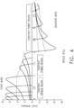
- Figure 4 is a torque speed characteristics graph for variable frequency operation of starter/generator induction machine 102 in accordance with an exemplary embodiment of the present invention.
- graph 700 includes a constant torque region 702 and a constant power region 704.
- starter/generator induction machine 102 is controlled to provide a maximum constant torque over a predetermined speed range by controlling the excitation current to keep a flux density in starter/generator induction machine 102 approximately equal to its saturation limit.
- the flux density in starter/generator induction machine 102 is proportional to V 1 /f. If this ratio is maintained substantially constant, the torque can be maintained substantially constant until at some frequency the voltage reaches the power source voltage limit and this ratio can no longer be maintained. As the frequency increases, the ratio, V 1 /f decreases, and the torque decreases while the power remains substantially constant.
- the rotor speed corresponding to this frequency is called base-speed, which is 1pu speed in Figure 4 .
- the figure illustrates constant torque and constant power regions related to start mode and generate mode. As indicated in the figure. when the speed is from 0 to 2pu and the torque is above zero, the machine is in start mode. Condactively. when the speed is from 2 to 4pu and the torque is below zero. the machine is in generate mode.
- the constant power region occurs after the rotor speed reaches the based speed. Obviously, the region includes partial start mode and full generate mode.
- starter/generator induction machine 102 is proximately proportional to VI 2/x (where, VI is machine voltage and x is leakage reactance), which indicates overload conditions at higher speed (higher than base speed) can not be achieved unless the voltage is increased to extend constant torque region 702 or reduce the leakage reactance of the machine.
- starter/generator induction machine 102 is over-sized, increasing the stack length or the rotor OD and reducing the number of turns
- starter/generator induction machine 102 includes 2p poles during the start mode and p poles during overload conditions.
- a power converter stage is coupled between the inverter and the battery bus to achieve a higher voltage to raise the voltage.
- FIG. 5 is a schematic block diagram of ICC unit 104 in accordance with an exemplary embodiment of the present invention.
- ICC unit 104 includes an electro-magnetic interference (EMI) filter 802, a bidirectional converter 804, a high frequency isolation transformer and an IGBT 3-phase inverter 808.
- EMI filter 802 provides the filtering to minimize the EMI susceptibility during start mode as well as generate mode.
- Bidirectional converter 804 includes two interleaved converters, which are phase shifted from each other. This arrangement of the interleaved converters minimizes the voltage ripple and increases ripple frequency. With lower ripple frequency, the required filtering is significantly reduced resulting in lower weight and size of EMI filter 802, improving power quality.
- a control board 810 includes a digital signal processor 812 for synchronized space vector pulse width modulation (SVPWM) and protection.
- a gate driver board 814 and power supply 816 may be provided as stand-alone components or may be incorporated into control board 810 or other component of ICC unit 104.
- EMI filter 802 is isolated in a separate compartment from the remaining electrical circuits to minimize noise interference and provide EMI immunity.
- the dual parallel converter stages are interleaved by appropriate gate driver control to minimize the ripple voltage and double the ripple frequency Such configuration tends to permit reducing a component weight and size of EMI filter 802 while improving the power quality.
- Control board 810 provides advanced space vector pulse width modulation (SVPWM) for controlling three-phase insulated gate bipolar transistor (IGBT) switches during the generate and start modes.
- SVPWM space vector pulse width modulation
- ICC unit 104 includes a thermal clad substrate for thermal management.
- the thermal clad substrate minimizes the thermal impedance and conducts the heat more efficiently and effectively compared to standard printed wiring circuit boards.
- the thermal clad substrate configuration provides for an efficient mechanical packaging and a relatively higher power density.
- the power switches are mounted on thermal clad substrate type circuit board.
- the gate driver boards are staggered above the power switches to minimize the wire lengths to the gates.
- the coldplate/heatsink forms a part of the main structure for the chassis
- a thermal interface material is placed between the coldplate and the power substrate.
- the power substrate is an insulated metal substrate (IMS) with typically a copper base material for good heat transfer.
- IMS insulated metal substrate
- An FR4 based circuit card assembly is positioned directly above the IMS and contains interface and driver circuits for the power devices.
- Bi-directional converter 804 acts as a boost-converter during the start up stage, converting the battery 28 Vdc power into high voltage at 200-230 Vdc. This high voltage is isolated from the battery power through the isolation step-up transformer in bidirectional converter 804.
- ICC unit 104 acts as a current source inverter.
- the high DC voltage from the output stage of bidirectional converter 804 is fed to IGBT 3-phase inverter 808 and SVPWM is used to control the IGBT switches, providing variable 3-phase AC voltage and frequency to starter/generator induction machine 102.
- the starting torque of starter/generator induction machine 102 is controlled by the voltage and frequency of bidirectional converter 804, which improves the battery energy utilization by controlling the battery current required during start mode.
- IGBT 3-phase inverter 808 includes the FPGA/DSP based control algorithm for SVPWM of the IGBT switches.
- 3-phase inverter 808 acts as an induction generator powered by the engine.
- starter/generator induction machine 102 speed reaches a minimum generate-mode speed, the power flow changes direction and starter/generator induction machine 102 acts as a generator, powering 3-phase inverter 808.
- 3-phase inverter 808 acts as a 6-pulse diode bridge converting starter/generator induction machine 102 3-phase voltage into 200-325 Vdc.
- 3-phase inverter 808 DC voltage is fed to bidirectional converter 804, which acts as a buck-converter converting high input DC voltage into regulated 28 Vdc.
- the output from bidirectional converter 804 passes through EMI filter 802 to provide 28 Vdc power to the aircraft DC bus.
- Zero voltage switching ZVS
- the system operates at high efficiency, high switching frequency and low switching losses.
- This converter topology also improves the bandwidth and dynamic response of the converter.
- Dual inter-leaved converter stages results in lower 28 Vdc ripple and twice the ripple frequency. This significantly reduces the filter weight and size, improving power quality.
- FIG. 6 is a schematic diagram of an algorithm for a rotor flux estimation method 900 in accordance with an exemplary embodiment of the present invention.
- indirect field orientation (IFO) vector control is used during start mode operation. IFO ensures that the torque and flux are controlled independently.
- the voltage-model flux-observer principle has been designed to estimate the rotor flux angle and from the rotor flux angle the rotor position is determined.
- Figure 9 In Figure 9 :
- FIG. 7 is a system block diagram of a start mode of starter/generator induction machine 102 in accordance with an exemplary embodiment of the present invention.
- starter/generator induction machine 102 provides sufficient torque to overcome the engine drag torque and to accelerate the engine.
- the starting torque of starter/generator induction machine 102 will plateau and then begin to drop after the engine is fired.
- the input voltage is first boosted to a higher, desirable voltage through a DC-DC converter.
- the gating of the boost converter is provided by the digital control board.
- the benefit of the voltage booster here is to reduce the current in the cascaded three phase inverter, and the cable between the DC-AC inverter and the three phase induction machine.
- the inverter Inverts the boosted DC voltage into three phase AC outputs that drive the induction motor.
- Digital control board 810 measures two of the three phase currents, i v and l h and converts the per phase quantities into i d and i q , where i d is the current aligning with the rotor flux linkage and i q is the current perpendicular to the rotor flux linkage. The great advantage of this conversion is to provide an optimal way to control an induction machine like a brush DC machine, i.e..
- i d controls the field of the machine just like controlling the current of the field winding ala brush DC machine
- i q controls the torque of the machine just like controlling the current of the armature winding of the brush DC machine.
- the orthogonality of the two currents allows the digital control board to optimize the output torque of the induction machine, permitting maximum efficiency of the system.
- the conversion requires the flux linkage position, so called rotor angle, to realize the transformation from i a and i b to i d and i q .
- the rotor angle is obtained through a mechanical position sensor mounted on the shaft of the machine.
- the rotor position is determined using currents, i ⁇ and i ⁇ , and the voltage commands, v ⁇ ⁇ and v ⁇ ⁇ using a flux linkage method.
- the entire approach for engine starting uniquely provides minimum currents and maximum efficiency performance of the system during start mode.
- FIG. 8 is a system block diagram for the sensorless control of starter/generator induction machine 102 (in generate mode) in accordance with an exemplary embodiment of the present invention.
- starter/generator induction machine 102 operates in a flux-weakening region at high speed.
- the battery voltage is boosted to obtain higher DC bus voltage using the boost converter stage during start mode.
- the converter voltage can be varied to high voltage as the back-EMF increases proportionally with the speed. In this case, to produce higher current and output higher torque such as 200% overloads.
- the full DC bus voltage needs to be utilized. Using the full DC bus voltage, a higher slip will produce a higher torque when the slip is changing between 0 and the pullout slip.
- the DC bus voltage is controlled to a constant value for example, but not limited to 30 Vdc and the output of the DC bus voltage PI controller is the slip speed.
- the rotor position and rotor speed are also estimated by the voltage-model flux-observer.
- the system synchronous speed is the sum of the slip speed and the estimated rotor speed. By integrating the synchronous speed, the synchronous flux-rotating angle is obtained. which is a parameter used for the field orientation control.
- starter/generator induction machine 102 is controlled such that starter/generator induction machine 102 works as a generator by appropriate gating signals provided by digital control board 810.
- the three phase output of starter/generator induction machine 102 is applied to the input of three phase converter 804.
- three phase AC-DC converter 804 converts the three phase AC voltage into a DC voltage that is higher than the desired output voltage of BS/G system 100.
- the cascaded DC-DC then bucks this internal DC bus down to the desired DC bus voltage at the output of converter 804.
- the rotor angle is obtained in the exemplary embodiment, by integrating the summation of the estimated rotor speed and the slip speed
- the slip speed is the output of the output voltage regulator as shown.
- the rotor angle is then used to convert the preset voltage commands, v ⁇ ⁇ and v ⁇ ⁇ , to the voltage commands that are ready to be translated to the gating signals.
- the exemplary embodiment permits the system to maximize the output of the generator. particularly at the upper end of the operating speed.
- the DC voltage at the output of the AC-DC voltage is permitted to be much higher than the output DC bus voltage due to the cascaded DC-DC converter, resulting in significant weight saving of the cable between the DC-DC converter and AC-DC converter as well as higher operating efficiency.
- the DC-DC converter is constructed with a soft switching mechanism built in, thus further increasing the efficiency of the system.
- the rotor angle is indirectly calculated by integrating the summation of the estimated speed and the slip speed, providing a robust sensor less method suited for maximizing the output of the starter/generator induction machine 102 in the generator mode without any position sensors.
- the start mode requirements of starter/generator induction machine 102 and ICC unit 104 are driven by the torque requirements of the respective engine.
- the parameters of the starter/generator induction machine 102 vary at different operating conditions. Generally, the current influences the inductance while the resistance changes are due to the temperature.
- the rotor position estimation is based on the parameters of the starter/generator induction machine 102, therefore resistance changes due to temperature are compensated for.
- the controller includes an adaptive parameter system and self-tuning...
- the battery Ah (Ampere-hour) rating is determined by the start up power requirement or the emergency power requirement.
- a BS/G system has the potential to reduce the size and weight of the battery as well as improve the life/reliability of the battery.
- the BS/G also offers competitive benefits against the brush type system to control the battery peak current during the startup.
- ICC unit 104 of the BS/G system includes the converter/inverter stages and the DSP-based startup mode torque control algorithm, which controls the required torque (V/Hz) during start mode. This topology and control algorithm ensures that the battery current during start mode has controlled peak current. In the case of a brush type DC system. the peak current from the battery is not controlled which results in higher stress on the battery compared to a brushless system.
- ICC unit 104 For the brushless system, if the external ground power is used instead of the battery. the peak current from the external source is controlled through programmed torque control algorithms inside ICC unit 104. Therefore, if the engine fails to start for multiple attempts, ICC unit 104 and starter/generator induction machine 102 experience decreased heating issues compared to that of the brush type system.
- FIG. 9 is a schematic block diagram of an ICC unit 900 in accordance with an alternative embodiment of the present invention.
- the A1. B1, C1 set 902 is connected to the upper set 906 of the ICC, while the A2. B2, C2 set 904 is connected to the lower set 908 of the ICC.
- This approach not only reduces filtering for EMI but also makes packaging of the overall ICC more achievable for the profile, weight, and size optimizations.
- processor refers to central processing units, microprocessors, microcontrollers, reduced instruction set circuits (RISC). application specific integrated circuits (ASIC), logic circuits, and any other circuit or processor capable of executing the functions described herein.
- RISC reduced instruction set circuits
- ASIC application specific integrated circuits
- the terms "software” and “firmware-' are interchangeable, and include any computer program stored in memory for execution by a processor, including RAM memory, ROM memory, EPROM memory, EEPROM memory, and non-volatile RAM (NVRAM) memory.
- RAM memory random access memory
- ROM memory read-only memory
- EPROM memory erasable programmable read-only memory
- EEPROM memory electrically erasable programmable read-only memory
- NVRAM non-volatile RAM
- the above-described embodiments of the disclosure may be implemented using computer programming or engineering techniques including computer software, firmware, hardware or any combination or subset thereof wherein the technical effect is for controlling a configuration and operation of a brushless starter/generator using sensorless commutation.
- Any such resulting program, having computer-readable code means may be embodied or provided within one or more computer-readable media, thereby making a computer program product, i.e.. an article of manufacture, according to the discussed embodiments of the disclosure.
- the computer readable media may be, for example, but is not limited to, a fixed (hard) drive, diskette, optical disk, magnetic tape. semiconductor memory such as read-only memory (ROM).
- the article of manufacture containing the computer code may be made and/or used by executing the code directly from one medium, by copying the code from one medium to another medium, or by transmitting the code over a network.
- the above-described embodiments of a method and systems for an engine starter/generator provides a cost-effective and reliable means for a relatively lightweight system for starting an engine and generating electrical power from the engine while running. More specifically, the methods and systems described herein facilitate controlling starting current and torque in the starter/generator during a starting mode. In addition, the above-described method and systems facilitate determining a rotor angle without using a rotor position sensor. Moreover, the addition of a second ICC doubles the ripple frequency and reduces the ripple magnitude caused by the PWM by approximately half without using any interface phase transformers (IPTs). As a result, this approach not only minimizes filtering for EMI but also makes packaging of the overall ICC more achievable for the profile. weight, and size optimizations. As a result, the method and systems described herein facilitate starting an engine and generating electrical power from the engine in a cost-effective and reliable manner.
- IPTs interface phase transformers
Landscapes
- Engineering & Computer Science (AREA)
- Chemical & Material Sciences (AREA)
- Combustion & Propulsion (AREA)
- Mechanical Engineering (AREA)
- General Engineering & Computer Science (AREA)
- Power Engineering (AREA)
- Control Of Eletrric Generators (AREA)
- Control Of Ac Motors In General (AREA)
Claims (15)
- Starter-/Generatorsystem (100) für ein Luftfahrzeugtriebwerk, wobei das Starter-/Generatorsystem (100) Folgendes umfasst:eine dreiphasige Käfigläuferinduktionsmaschine (102); undeine erste dreiphasige Wechselrichter/Wandler/Steuerungs(inverter/converter/controller - ICC)-Einheit (104, 900), die über einen ersten elektrischen Pfad mit der dreiphasigen Käfigläuferinduktionsmaschine (102) wirkgekoppelt ist, wobei die ICC-Einheit (104, 900) Folgendes umfasst:einen dreiphasigen Wechselrichter/Wandler (808), der mit der dreiphasigen Käfigläuferinduktionsmaschine (102) elektrisch gekoppelt ist;einen bidirektionalen Gleichstrom-Gleichstrom-Wandler (804), der mit dem dreiphasigen Wechselrichter/Wandler (808) elektrisch gekoppelt ist; undeine digitale Steuerplatine (810), die konfiguriert ist, um einen Rotorwinkel aus mehreren Phasenströmen zu der Induktionsmaschine (102) während eines Startmodus sensorlos zu bestimmen und um den Rotorwinkel durch Integrieren einer Summe einer geschätzten Rotordrehzahl und einer Schlupfdrehzahl während eines Erzeugungsmodus zu bestimmen;wobei, während eines Startmodus, eine Logik in der digitalen Steuerplatine (810) das Starter-/Generatorsystem (100) in eine Kombination aus einem Induktionsmotor unter Verwendung der Induktionsmaschine (102), einem dreiphasigen Gleichstrom-Wechselstrom-Wechselrichter unter Verwendung des Wechselrichters/Wandlers (808) und einem Gleichstrom-Gleichstrom-Aufwärtswandler unter Verwendung des bidirektionalen Gleichstrom-Gleichstrom-Wandlers (804) konfiguriert, und, während eines Erzeugungsmodus, die Logik in der digitalen Steuerplatine (810) das Starter-/Generatorsystem (100) in eine Kombination aus einem Induktionsgenerator unter Verwendung der Induktionsmaschinen (102), einem dreiphasigen Wechselstrom-Gleichstrom-Wandler unter Verwendung des Wechselrichters/Wandlers (808) und einem Gleichstrom-Gleichstrom-Abwärtswandler unter Verwendung des bidirektionalen Gleichstrom-Gleichstrom-Wandlers (804) konfiguriert.
- Starter-/Generatorsystem (100) nach Anspruch 1, wobei eine Kommutierung des dreiphasigen Wechselrichters/Wandlers (808) unter Verwendung eines sensorlosen Mechanismus bestimmt wird.
- Starter-/Generatorsystem (100) nach Anspruch 1, wobei der Gleichstrom-Gleichstrom-Aufwärtswandler konfiguriert ist, um eine Eingangsleistung von einem ersten Spannungswert auf einen zweiten Spannungswert zu erhöhen, wobei der zweite Wert betragsmäßig größer als der erste Wert ist.
- Starter-/Generatorsystem (100) nach Anspruch 1, wobei die digitale Steuerplatine (810) für Folgendes konfiguriert ist:Messen von zwei der drei Phasenströme (ia, ib ) des Induktionsmotors; undUmwandeln der Mengen von Phasenströmen (ia, ib ) pro Phase in einen Strom (id ), der an der Rotorflussverbindung ausgerichtet ist, und einen Strom (iq ), der senkrecht zu der Rotorflussverbindung ist;Steuern des Feldes des Induktionsmotors unter Verwendung des Stroms (id ), der an der Rotorflussverbindung ausgerichtet ist; undSteuern des Drehmoments des Induktionsmotors unter Verwendung von Strom (iq ), der senkrecht zu der Rotorflussverbindung ist.
- Starter-/Generatorsystem (100) nach Anspruch 4, wobei die digitale Steuerplatine (810) ferner konfiguriert ist, um einen Rotorwinkel des Induktionsmotors unter Verwendung der Ströme ia und ib und eines ersten Spannungsbefehls v*α und eines zweiten Spannungsbefehls v*β zu bestimmen.
- Starter-/Generatorsystem (100) nach Anspruch 4, wobei die digitale Steuerplatine (810) ferner konfiguriert ist, um einen Rotorwinkel des Induktionsmotors unter Verwendung eines Flussverbindungsverfahrens zu bestimmen.
- Starter-/Generatorsystem (100) nach Anspruch 1, das ferner eine zweite dreiphasige Wechselrichter/Wandler/Steuerungs(ICC)-Einheit (104, 900) umfasst, die über einen zweiten elektrischen Pfad, der parallel zu dem ersten elektrischen Pfad ist, mit der dreiphasigen Käfigläuferinduktionsmaschine (102) wirkgekoppelt ist, wobei die zweite ICC-Einheit (104, 900) Folgendes umfasst:einen dreiphasigen Wechselrichter/Wandler (808), der mit der dreiphasigen Käfigläuferinduktionsmaschine (102) elektrisch gekoppelt ist;einen bidirektionalen Gleichstrom-Gleichstrom-Wandler (804), der mit dem dreiphasigen Wechselrichter/Wandler (808) elektrisch gekoppelt ist; undeine digitale Steuerplatine (810), die konfiguriert ist, um einen Rotorwinkel aus mehreren Phasenströmen zu der Induktionsmaschine (102) während eines Startmodus sensorlos zu bestimmen.
- Starter-/Generatorsystem (100) nach Anspruch 1, wobei die digitale Steuerplatine (810) konfiguriert ist, um die Schlupfdrehzahl aus einem Ausgang des Ausgangsspannungsreglers zu bestimmen.
- Starter-/Generatorsystem (100) nach Anspruch 1, wobei die digitale Steuerplatine (810) konfiguriert ist, um einen ersten voreingestellten Spannungsbefehl v*d und einen zweiten voreingestellten Spannungsbefehl v*q unter Verwendung des Rotorwinkels in entsprechende Spannungsbefehle umzuwandeln, um den Wechselstrom-Gleichstrom-Wandler anzusteuern.
- Starter-/Generatorsystem (100) nach einem der vorhergehenden Ansprüche, wobei der bidirektionale Gleichstrom-Gleichstrom-Wandler zwei verschachtelte Wandler beinhaltet, die zueinander phasenverschoben sind.
- Starter-/Generatorsystem (100) nach dem vorhergehenden Anspruch, wobei die ICC-Einheit (104, 900) ein Filter für elektromagnetische Interferenz (electromagnetic interference - EMI) (802), einen Hochfrequenzisolationstransformator und einen 3-Phasen-IGBT-Wechselrichter (808) beinhaltet, wobei das EMI-Filter (802) vorzugsweise in einem separaten Fach von den verbleibenden elektrischen Schaltungen isoliert ist, um Rauschstörungen zu minimieren und EMI-Immunität bereitzustellen.
- Triebwerkstarter für Luftfahrzeuge und Generator von elektrischer Leistung für Luftfahrzeuge, die ein Starter/Generatorsystem (100) nach einem der vorhergehenden Ansprüche umfassen, die konfiguriert sind, um von außen zugeführte elektrische Leistung aufzunehmen, um die Induktionsmaschine (102) anzutreiben, die ihrerseits konfiguriert ist, um einen Gasturbinenzyklus des Luftfahrzeugtriebwerks zu starten, und konfiguriert ist, um elektrische Leistung zu erzeugen, sobald das Luftfahrzeugtriebwerk in Betrieb ist.
- Verfahren zum Steuern eines Triebwerkstarter-/Generatorsystems zum Starten eines Luftfahrzeugtriebwerks und Erzeugen von Leistung unter Verwendung des Triebwerks, wobei das Verfahren Folgendes umfasst:
während eines Startmodus:Erhöhen einer Eingangsspannung unter Verwendung eines Gleichstrom-Gleichstrom-Wandlers (804);Wechselrichten der erhöhten Gleichstromspannung in einen dreiphasigen Wechselstromausgang, der einen Induktionsmotor antreibt, der konfiguriert ist, um den Motor zu drehen;Messen von zwei der drei Phasenströme (ia, ib);Umwandeln der gemessenen Phasenströme (ia, ib ) in einen Strom (id ), der an einer Rotorflussverbindung ausgerichtet ist, und einen Strom (iq ), der senkrecht zu der Rotorflussverbindung ist, vorzugsweise unter Verwendung einer Flussverbindungsposition eines Rotors des Induktionsmotors;Steuern eines Felds einer Induktionsmaschine (102) des Starter-/Generatorsystems unter Verwendung des Stroms (id ), der an einer Rotorflussverbindung ausgerichtet ist;Steuern eines Drehmoments einer Induktionsmaschine (102) des Starter-/Generatorsystems unter Verwendung des Stroms (iq ), der senkrecht zu der Rotorflussverbindung ist.während eines Erzeugungsmodus:Anlegen eines dreiphasigen Ausgangs der Induktionsmaschine (102) an den Eingang eines dreiphasigen Wandlers, um eine dreiphasige Wechselstromspannung zu erzeugen;Umwandeln der dreiphasigen Wechselstromspannung in eine Gleichstromspannung mit einem ersten Spannungsbetrag, der größer als ein zuvor bestimmter Ausgangsspannungsbetrag des Starter-/Generatorsystems ist;Abwärtswandeln der Gleichstromspannung auf den zuvor bestimmten Ausgangsspannungsbetrag des Starter-/Generatorsystems unter Verwendung eines kaskadierten Gleichstrom-Gleichstrom-Wandlers; undBestimmen eines Rotorwinkels durch Integrieren einer Summe einer geschätzten Rotordrehzahl und einer Schlupfdrehzahl. - Verfahren nach Anspruch 13, wobei die Schlupfdrehzahl der Ausgang eines Ausgangsspannungsreglers ist.
- Verfahren nach Anspruch 13, das ferner das Ansteuern des Wechselstrom-Gleichstrom-Wandlers, der einen ersten voreingestellten Spannungsbefehl v*d und einen zweiten voreingestellten Spannungsbefehl v*q unter Verwendung des Rotorwinkels in entsprechende Spannungsbefehle umwandelt; und/oder das Ansteuern des Gleichstrom-Gleichstrom-Wandlers (804) unter Verwendung einer digitalen Steuerplatine (810) umfasst.
Applications Claiming Priority (2)
| Application Number | Priority Date | Filing Date | Title |
|---|---|---|---|
| US12/347,616 US8030788B2 (en) | 2008-12-31 | 2008-12-31 | Method and systems for an engine starter/generator |
| PCT/US2009/067497 WO2010077766A2 (en) | 2008-12-31 | 2009-12-10 | Method and systems for an engine starter/generator |
Publications (2)
| Publication Number | Publication Date |
|---|---|
| EP2384397A2 EP2384397A2 (de) | 2011-11-09 |
| EP2384397B1 true EP2384397B1 (de) | 2022-03-02 |
Family
ID=42102186
Family Applications (1)
| Application Number | Title | Priority Date | Filing Date |
|---|---|---|---|
| EP09799219.2A Active EP2384397B1 (de) | 2008-12-31 | 2009-12-10 | Verfahren und vorrichtungen für einen starter-generator einer maschine |
Country Status (5)
| Country | Link |
|---|---|
| US (1) | US8030788B2 (de) |
| EP (1) | EP2384397B1 (de) |
| JP (1) | JP5802134B2 (de) |
| CA (1) | CA2748257C (de) |
| WO (1) | WO2010077766A2 (de) |
Cited By (1)
| Publication number | Priority date | Publication date | Assignee | Title |
|---|---|---|---|---|
| US12151670B2 (en) | 2022-06-17 | 2024-11-26 | Bae Systems Controls Inc. | Parallel variable speed generator control |
Families Citing this family (68)
| Publication number | Priority date | Publication date | Assignee | Title |
|---|---|---|---|---|
| US7999403B2 (en) * | 2008-06-24 | 2011-08-16 | General Electric Company | System and method for locomotive engine cranking |
| US8300438B1 (en) * | 2008-11-16 | 2012-10-30 | Edward Herbert | Power factor corrected 3-phase Ac-dc power converter using natural modulation |
| US8450888B2 (en) * | 2009-04-20 | 2013-05-28 | General Electric Company | Integrated brushless starter/generator system |
| US8467949B2 (en) * | 2009-05-29 | 2013-06-18 | Honeywell International Inc. | Methods and systems for turbine line replaceable unit fault detection and isolation during engine startup |
| DE102009027828A1 (de) * | 2009-07-20 | 2011-01-27 | Robert Bosch Gmbh | Steuerung und Verfahren eines Startermotors für eine Startvorrichtung |
| US8378644B2 (en) * | 2009-08-28 | 2013-02-19 | Hamilton Sundstrand Corporation | Active rectification for a variable-frequency synchronous generator |
| JP2013517405A (ja) * | 2009-12-17 | 2013-05-16 | ドイツ アクチェンゲゼルシャフト | 一体型スタータ・ジェネレータを有する移動式作業機械 |
| JP5404790B2 (ja) * | 2010-02-09 | 2014-02-05 | パナソニック株式会社 | 電力変換装置及びそれを備える燃料電池システム |
| US8497591B2 (en) * | 2010-12-29 | 2013-07-30 | General Electric Company | System and method for off-highway vehicle engine cranking |
| US8644992B2 (en) * | 2011-05-05 | 2014-02-04 | General Electric Company | Method to improve washer motor efficiency and performance |
| JP2012246905A (ja) * | 2011-05-31 | 2012-12-13 | Denso Corp | スタータ |
| JP5444304B2 (ja) * | 2011-10-25 | 2014-03-19 | ファナック株式会社 | 無効電流指令作成部を有するモータ駆動装置 |
| FR2982911B1 (fr) * | 2011-11-18 | 2013-11-15 | Valeo Equip Electr Moteur | Demarreur electrique a filtre electronique integre pour moteur a combustion interne |
| TWI439041B (zh) | 2011-12-19 | 2014-05-21 | 財團法人工業技術研究院 | 永磁同步馬達驅動方法與裝置 |
| GB2500937B (en) * | 2012-04-05 | 2015-04-08 | Control Tech Ltd | Fail-safe interface |
| JP5903628B2 (ja) * | 2012-06-14 | 2016-04-13 | パナソニックIpマネジメント株式会社 | 電力変換装置 |
| EP2752330B1 (de) * | 2013-01-04 | 2018-03-07 | Visedo Oy | Mobile Arbeitsmaschine mit angepasster Zwischenkreisspannungsregelung |
| US9537437B2 (en) * | 2013-03-04 | 2017-01-03 | General Electric Company | Method and system for controlling switching frequency of a doubly-fed induction generator (DFIG) |
| KR101759371B1 (ko) * | 2013-04-04 | 2017-07-18 | 엘에스산전 주식회사 | 유도전동기의 센서리스 벡터 제어 장치 |
| US20140375405A1 (en) * | 2013-06-21 | 2014-12-25 | Hamilton Sundstrand Corporation | Systems and methods for inductively coupled damper for direct current power systems |
| US9533638B2 (en) * | 2013-07-18 | 2017-01-03 | The Boeing Company | Aircraft universal power converter |
| US9035478B2 (en) * | 2013-08-26 | 2015-05-19 | Ge Aviation Systems, Llc | Aircraft engine constant frequency starter/generator |
| JP6248203B2 (ja) | 2013-09-06 | 2017-12-13 | ジーイー・アビエイション・システムズ・エルエルシー | 航空機エンジンを始動するための方法 |
| US9041232B2 (en) | 2013-10-11 | 2015-05-26 | General Electric Company | Electric generator system |
| DE102013017419A1 (de) | 2013-10-19 | 2014-07-31 | Daimler Ag | Ladeschaltung für einen On-Board-Lader eines Fahrzeugs |
| US9692234B2 (en) * | 2013-10-21 | 2017-06-27 | Stc.Unm | Systems and methods for distributing power using photovoltaic resources and a shifting battery system |
| US20150158390A1 (en) * | 2013-12-09 | 2015-06-11 | Textron Inc. | Using DC Motor With A Controller As A Generator |
| FR3015571B1 (fr) * | 2013-12-23 | 2018-11-23 | Safran Helicopter Engines | Procede et systeme de demarrage fiabilise de turbomachine |
| US9977858B2 (en) * | 2014-07-03 | 2018-05-22 | The Boeing Company | Electromagnetic interference filters for power converter applications |
| CN105471330A (zh) * | 2014-08-08 | 2016-04-06 | 德昌电机(深圳)有限公司 | 同步电机驱动电路 |
| CN107634683B (zh) * | 2014-08-08 | 2020-03-24 | 德昌电机(深圳)有限公司 | 同步电机驱动电路 |
| CN104300820B (zh) * | 2014-09-25 | 2016-10-26 | 南京航空航天大学 | 一种两级式三相三电平光伏并网逆变器的数字控制方法 |
| US9917490B2 (en) * | 2014-11-21 | 2018-03-13 | Hamilton Sundstrand Corporation | Tail cone generator with integral speed increasing gearbox |
| US20160304214A1 (en) * | 2015-04-20 | 2016-10-20 | Hamilton Sundstrand Corporation | Emergency power sources for propulsion systems |
| AT517397B1 (de) * | 2015-07-07 | 2017-10-15 | Ge Jenbacher Gmbh & Co Og | Anordnung mit einem Synchrongenerator und einer Asynchronmaschine |
| CN105071738B (zh) * | 2015-08-31 | 2017-11-10 | 中国兵器工业集团第二O二研究所 | 永磁同步电机转子磁极磁通链α轴及β轴分量观测方法 |
| US9876421B2 (en) * | 2015-10-09 | 2018-01-23 | Semiconductor Components Industries, Llc | Power supply controller and related methods |
| WO2017066307A1 (en) * | 2015-10-13 | 2017-04-20 | Suntech Drive, Llc | Variable speed maximum power point tracking, solar electric motor controller for induction and permanent magnet ac motors |
| US20170107910A1 (en) * | 2015-10-15 | 2017-04-20 | Ge Aviation Systems Llc | Method and apparatus for starting an aircraft engine and operating a power architecture for an aircraft |
| FR3042659B1 (fr) | 2015-10-20 | 2018-09-28 | Labinal Power Systems | Demarreur-generateur de turbomachine a machine electrique asynchrone multi-enroulements |
| EP3414449B1 (de) * | 2016-02-11 | 2021-03-31 | Sedemac Mechatronics PVT Ltd | Verfahren und system zum andrehen eines verbrennungsmotors |
| US10472084B2 (en) | 2016-03-21 | 2019-11-12 | Honeywell International Inc. | Motor-generator for high efficiency auxiliary power system |
| US10374486B2 (en) | 2017-03-24 | 2019-08-06 | Ge Aviation Systems Llc | Method and assembly of an electric machine |
| US10381900B2 (en) | 2017-03-24 | 2019-08-13 | Ge Aviation Systems Llc | Method and assembly of an electric machine |
| US10483887B2 (en) | 2017-08-11 | 2019-11-19 | Rolls-Royce North American Technologies, Inc. | Gas turbine generator temperature DC to DC converter control system |
| US10476417B2 (en) * | 2017-08-11 | 2019-11-12 | Rolls-Royce North American Technologies Inc. | Gas turbine generator torque DC to DC converter control system |
| US10491145B2 (en) | 2017-08-11 | 2019-11-26 | Rolls-Royce North American Technologies Inc. | Gas turbine generator speed DC to DC converter control system |
| CN107313886B (zh) * | 2017-08-21 | 2019-09-24 | 重庆瑜欣平瑞电子股份有限公司 | 一种通用汽油机逆向启动模块电路 |
| CN110617112A (zh) * | 2019-08-27 | 2019-12-27 | 肇庆高新区伙伴汽车技术有限公司 | 齿轮转子发动机及其机组 |
| CN110941927B (zh) * | 2019-12-25 | 2022-03-11 | 哈尔滨工业大学 | 一种永磁同步电机转子动偏心位移计算方法 |
| CN112952784B (zh) * | 2021-02-24 | 2024-05-10 | 国网浙江省电力有限公司电力科学研究院 | 适用于柔性励磁系统的励磁变过负荷限制器 |
| CN111348203B (zh) * | 2020-03-27 | 2023-05-26 | 扬州翊翔航空科技有限公司 | 一种手持式航空混合动力系统的起动装置及其控制方法 |
| US11605957B2 (en) | 2020-07-15 | 2023-03-14 | General Electric Company | Dynamic power supply system |
| KR102528007B1 (ko) | 2020-12-21 | 2023-05-03 | 현대모비스 주식회사 | 대용량 양방향 절연형 dc-dc 컨버터 어셈블리 및 냉각구조 |
| EP4040651A1 (de) * | 2021-02-08 | 2022-08-10 | Hamilton Sundstrand Corporation | Motor und motorantriebsanordnung |
| US20220281327A1 (en) * | 2021-03-07 | 2022-09-08 | Alexander Diaz | Self Powered EV System |
| US11353511B1 (en) | 2021-07-02 | 2022-06-07 | Beta Air, Llc | Methods and systems for electric propulsor fault detection |
| US11686751B2 (en) | 2021-07-02 | 2023-06-27 | Beta Air, Llc | Methods and systems for electric propulsor fault detection |
| US11476784B1 (en) * | 2021-07-09 | 2022-10-18 | Allegro Microsystems, Llc | Low acoustic noise open loop motor startup |
| US11652428B2 (en) | 2021-07-14 | 2023-05-16 | General Electric Company | Method and apparatus for controlling a motor |
| US12348130B2 (en) | 2021-09-14 | 2025-07-01 | General Electric Company | EMI noise reduction circuit for DC/DC converter |
| CN113852316B (zh) * | 2021-09-30 | 2025-01-17 | 陕西航空电气有限责任公司 | 一种基于模型预测控制的发电机起动控制方法及装置 |
| US12234022B2 (en) | 2022-08-12 | 2025-02-25 | Rolls-Royce North American Technologies, Inc. | Electrical energy system for barring rotor |
| US12334859B2 (en) | 2022-08-12 | 2025-06-17 | Rolls-Royce North American Technologies, Inc. | Gas-turbine electrical start system |
| DE102022121516A1 (de) * | 2022-08-25 | 2024-03-07 | Audi Aktiengesellschaft | Erregerschaltung für eine fremderregte Synchronmaschine, Kraftfahrzeug und Verfahren zur Entregung einer Erregerwicklung |
| CN115839277B (zh) * | 2022-12-20 | 2025-06-06 | 中国航发控制系统研究所 | 一种航空发动机及其功率提取与分配方法 |
| US12537426B2 (en) | 2023-08-03 | 2026-01-27 | Ge Aviation Systems Llc | Electrical machine and method of operating electrical machine |
| US12401303B2 (en) | 2023-09-08 | 2025-08-26 | Allegro Microsystems, Llc | Low acoustic noise open loop motor startup |
Family Cites Families (26)
| Publication number | Priority date | Publication date | Assignee | Title |
|---|---|---|---|---|
| FR2607185B1 (fr) | 1986-11-20 | 1990-05-04 | Snecma | Systeme de lubrification pour demarreur de turbomachine |
| US4922119A (en) | 1988-11-29 | 1990-05-01 | Sundstrand Corporation | Integrated starting system |
| US5055700A (en) | 1989-10-16 | 1991-10-08 | Dhyanchand P John | Brushless generator having prime mover start capability |
| JP2879486B2 (ja) * | 1992-03-06 | 1999-04-05 | 日野自動車工業株式会社 | 内燃機関の制動および補助動力装置 |
| US5559419A (en) | 1993-12-22 | 1996-09-24 | Wisconsin Alumni Research Foundation | Method and apparatus for transducerless flux estimation in drives for induction machines |
| US5657219A (en) * | 1995-08-29 | 1997-08-12 | Crown International, Inc. | Opposed current power converter |
| DE19532164A1 (de) | 1995-08-31 | 1997-03-06 | Clouth Gummiwerke Ag | Antriebssystem, insbesondere für ein Kraftfahrzeug, und Verfahren zum Betreiben desselben |
| US6089849A (en) * | 1998-02-27 | 2000-07-18 | Van Dorn Demag Corporation | Hybrid injection molding machine |
| KR100371369B1 (ko) | 2000-08-18 | 2003-02-06 | 엘지산전 주식회사 | 유도 전동기의 벡터 제어 시스템 |
| WO2003073185A2 (en) * | 2002-02-28 | 2003-09-04 | Zetacon Corporation | Predictive control system and method |
| GB0208600D0 (en) * | 2002-04-15 | 2002-05-22 | Nottingham University | Power converter |
| TW200404402A (en) * | 2002-05-24 | 2004-03-16 | Virginia Tech Intell Prop | Apparatus for drive control, power conversion, and start-up control in a PMBDCM or two-phase SRM drive system |
| US6903470B2 (en) | 2002-08-22 | 2005-06-07 | Honeywell International, Inc. | High speed generator with high-power rotating rectifiers cooling system |
| JP2004282969A (ja) * | 2003-03-19 | 2004-10-07 | Hitachi Ltd | 交流電動機の制御装置及び制御方法 |
| JP4238646B2 (ja) * | 2003-06-16 | 2009-03-18 | 株式会社安川電機 | 誘導電動機の速度センサレスベクトル制御装置 |
| US6844707B1 (en) | 2003-12-30 | 2005-01-18 | Pacific Scientific/Electro Kinetics Division | AC/DC brushless starter-generator |
| KR100848185B1 (ko) * | 2004-06-10 | 2008-07-23 | 인터내쇼널 렉티파이어 코포레이션 | Emi 방출을 저감하기 위해 전기 모터를 제어하는 방법 |
| US7208908B2 (en) | 2004-07-12 | 2007-04-24 | Honeywell International Inc. | Apparatus and method to control torque and voltage of an AC machine |
| JP2006203957A (ja) * | 2004-12-21 | 2006-08-03 | Denso Corp | ターボチャージャアシスト電動機 |
| EP1834402A1 (de) * | 2005-01-07 | 2007-09-19 | Ronald De Four | Selbststartendes verfahren und vorrichtung zur sensorlosen kommutierung von bürstenlosen gleichstrommotoren |
| US7808201B2 (en) | 2005-06-09 | 2010-10-05 | International Rectifier Corporation | Sensorless field oriented controller for two-phase motor |
| US7233125B2 (en) * | 2005-09-01 | 2007-06-19 | Stmicroelectronics, Inc. | System and method for controlling an induction motor |
| US7687928B2 (en) | 2006-06-14 | 2010-03-30 | Smiths Aerospace, Llc | Dual-structured aircraft engine starter/generator |
| WO2008053554A1 (fr) * | 2006-11-02 | 2008-05-08 | Mitsubishi Electric Corporation | Appareil de commande de voiture à moteur électrique |
| FR2911916B1 (fr) | 2007-01-30 | 2009-03-27 | Hispano Suiza Sa | Moteur a turbine a gaz incorporant un demarreur monte sur la boite a engrenages |
| US7957166B2 (en) * | 2007-10-30 | 2011-06-07 | Johnson Controls Technology Company | Variable speed drive |
-
2008
- 2008-12-31 US US12/347,616 patent/US8030788B2/en active Active
-
2009
- 2009-12-10 CA CA2748257A patent/CA2748257C/en not_active Expired - Fee Related
- 2009-12-10 EP EP09799219.2A patent/EP2384397B1/de active Active
- 2009-12-10 JP JP2011543558A patent/JP5802134B2/ja not_active Expired - Fee Related
- 2009-12-10 WO PCT/US2009/067497 patent/WO2010077766A2/en not_active Ceased
Cited By (1)
| Publication number | Priority date | Publication date | Assignee | Title |
|---|---|---|---|---|
| US12151670B2 (en) | 2022-06-17 | 2024-11-26 | Bae Systems Controls Inc. | Parallel variable speed generator control |
Also Published As
| Publication number | Publication date |
|---|---|
| CA2748257A1 (en) | 2010-07-08 |
| JP2012514447A (ja) | 2012-06-21 |
| EP2384397A2 (de) | 2011-11-09 |
| WO2010077766A3 (en) | 2011-02-24 |
| WO2010077766A2 (en) | 2010-07-08 |
| US20100164428A1 (en) | 2010-07-01 |
| CA2748257C (en) | 2018-01-09 |
| US8030788B2 (en) | 2011-10-04 |
| JP5802134B2 (ja) | 2015-10-28 |
Similar Documents
| Publication | Publication Date | Title |
|---|---|---|
| EP2384397B1 (de) | Verfahren und vorrichtungen für einen starter-generator einer maschine | |
| CN101584102B (zh) | 机电能量转换系统 | |
| JP5568129B2 (ja) | 航空機エンジンの始動/発電システム及び制御方法 | |
| Bu et al. | Induction-machine-based starter/generator systems: Techniques, developments, and advances | |
| US9917544B2 (en) | Method and power converter unit for operating a generator | |
| KR102237773B1 (ko) | 전력 시스템의 제어 방법 및 전력 시스템 | |
| JP4882053B2 (ja) | 超電導回転電機駆動制御システム | |
| Ivankovic et al. | Power Electronic Solutions to Improve the | |
| CN112532128A (zh) | 一种航空大功率复合无刷起动发电系统及其控制方法 | |
| EP1232562B1 (de) | Statischer induktionsstart für einen turbinengenerator mit bürstenlosem erreger und zugehörige verfahren | |
| Mitcham et al. | An integrated LP shaft generator for the more electric aircraft | |
| CA3204631A1 (en) | Energy efficient induction motor | |
| US12176834B2 (en) | Energy efficient induction motor | |
| RU2645866C2 (ru) | Электромеханическая система приведения в действие и/или генерирования, содержащая электрическую изоляцию между источником электрического напряжения и нагрузкой | |
| Chu et al. | Salient pole wound field synchronous machine for marine propulsors with outboard drives: Analysis and design | |
| Kasten et al. | Double inverter concept for high-speed drives without motor filters | |
| US20250309782A1 (en) | Power converter and system for an engine starter generator | |
| Leclere et al. | A new concept of PTI/PTO for marine applications | |
| CN121036462A (zh) | 一种无刷励磁同步发电机 | |
| CN120615273A (zh) | 用于多相驱动器的能源供给 |
Legal Events
| Date | Code | Title | Description |
|---|---|---|---|
| PUAI | Public reference made under article 153(3) epc to a published international application that has entered the european phase |
Free format text: ORIGINAL CODE: 0009012 |
|
| 17P | Request for examination filed |
Effective date: 20110824 |
|
| AK | Designated contracting states |
Kind code of ref document: A2 Designated state(s): AT BE BG CH CY CZ DE DK EE ES FI FR GB GR HR HU IE IS IT LI LT LU LV MC MK MT NL NO PL PT RO SE SI SK SM TR |
|
| DAX | Request for extension of the european patent (deleted) | ||
| STAA | Information on the status of an ep patent application or granted ep patent |
Free format text: STATUS: EXAMINATION IS IN PROGRESS |
|
| 17Q | First examination report despatched |
Effective date: 20180306 |
|
| REG | Reference to a national code |
Ref country code: DE Ref legal event code: R079 Ref document number: 602009064320 Country of ref document: DE Free format text: PREVIOUS MAIN CLASS: F02N0015080000 Ipc: F02N0015000000 |
|
| GRAP | Despatch of communication of intention to grant a patent |
Free format text: ORIGINAL CODE: EPIDOSNIGR1 |
|
| STAA | Information on the status of an ep patent application or granted ep patent |
Free format text: STATUS: GRANT OF PATENT IS INTENDED |
|
| RIC1 | Information provided on ipc code assigned before grant |
Ipc: F02N 11/08 20060101ALN20210909BHEP Ipc: F02N 11/04 20060101ALN20210909BHEP Ipc: F02C 7/268 20060101ALI20210909BHEP Ipc: H02P 21/24 20160101ALI20210909BHEP Ipc: F01D 15/10 20060101ALI20210909BHEP Ipc: F02N 15/00 20060101AFI20210909BHEP |
|
| INTG | Intention to grant announced |
Effective date: 20210928 |
|
| GRAS | Grant fee paid |
Free format text: ORIGINAL CODE: EPIDOSNIGR3 |
|
| GRAA | (expected) grant |
Free format text: ORIGINAL CODE: 0009210 |
|
| STAA | Information on the status of an ep patent application or granted ep patent |
Free format text: STATUS: THE PATENT HAS BEEN GRANTED |
|
| AK | Designated contracting states |
Kind code of ref document: B1 Designated state(s): AT BE BG CH CY CZ DE DK EE ES FI FR GB GR HR HU IE IS IT LI LT LU LV MC MK MT NL NO PL PT RO SE SI SK SM TR |
|
| REG | Reference to a national code |
Ref country code: GB Ref legal event code: FG4D |
|
| REG | Reference to a national code |
Ref country code: CH Ref legal event code: EP Ref country code: AT Ref legal event code: REF Ref document number: 1472431 Country of ref document: AT Kind code of ref document: T Effective date: 20220315 |
|
| REG | Reference to a national code |
Ref country code: DE Ref legal event code: R096 Ref document number: 602009064320 Country of ref document: DE |
|
| REG | Reference to a national code |
Ref country code: IE Ref legal event code: FG4D |
|
| REG | Reference to a national code |
Ref country code: LT Ref legal event code: MG9D |
|
| REG | Reference to a national code |
Ref country code: NL Ref legal event code: MP Effective date: 20220302 |
|
| PG25 | Lapsed in a contracting state [announced via postgrant information from national office to epo] |
Ref country code: SE Free format text: LAPSE BECAUSE OF FAILURE TO SUBMIT A TRANSLATION OF THE DESCRIPTION OR TO PAY THE FEE WITHIN THE PRESCRIBED TIME-LIMIT Effective date: 20220302 Ref country code: NO Free format text: LAPSE BECAUSE OF FAILURE TO SUBMIT A TRANSLATION OF THE DESCRIPTION OR TO PAY THE FEE WITHIN THE PRESCRIBED TIME-LIMIT Effective date: 20220602 Ref country code: LT Free format text: LAPSE BECAUSE OF FAILURE TO SUBMIT A TRANSLATION OF THE DESCRIPTION OR TO PAY THE FEE WITHIN THE PRESCRIBED TIME-LIMIT Effective date: 20220302 Ref country code: HR Free format text: LAPSE BECAUSE OF FAILURE TO SUBMIT A TRANSLATION OF THE DESCRIPTION OR TO PAY THE FEE WITHIN THE PRESCRIBED TIME-LIMIT Effective date: 20220302 Ref country code: ES Free format text: LAPSE BECAUSE OF FAILURE TO SUBMIT A TRANSLATION OF THE DESCRIPTION OR TO PAY THE FEE WITHIN THE PRESCRIBED TIME-LIMIT Effective date: 20220302 Ref country code: BG Free format text: LAPSE BECAUSE OF FAILURE TO SUBMIT A TRANSLATION OF THE DESCRIPTION OR TO PAY THE FEE WITHIN THE PRESCRIBED TIME-LIMIT Effective date: 20220602 |
|
| REG | Reference to a national code |
Ref country code: AT Ref legal event code: MK05 Ref document number: 1472431 Country of ref document: AT Kind code of ref document: T Effective date: 20220302 |
|
| PG25 | Lapsed in a contracting state [announced via postgrant information from national office to epo] |
Ref country code: PL Free format text: LAPSE BECAUSE OF FAILURE TO SUBMIT A TRANSLATION OF THE DESCRIPTION OR TO PAY THE FEE WITHIN THE PRESCRIBED TIME-LIMIT Effective date: 20220302 Ref country code: LV Free format text: LAPSE BECAUSE OF FAILURE TO SUBMIT A TRANSLATION OF THE DESCRIPTION OR TO PAY THE FEE WITHIN THE PRESCRIBED TIME-LIMIT Effective date: 20220302 Ref country code: GR Free format text: LAPSE BECAUSE OF FAILURE TO SUBMIT A TRANSLATION OF THE DESCRIPTION OR TO PAY THE FEE WITHIN THE PRESCRIBED TIME-LIMIT Effective date: 20220603 Ref country code: FI Free format text: LAPSE BECAUSE OF FAILURE TO SUBMIT A TRANSLATION OF THE DESCRIPTION OR TO PAY THE FEE WITHIN THE PRESCRIBED TIME-LIMIT Effective date: 20220302 |
|
| PG25 | Lapsed in a contracting state [announced via postgrant information from national office to epo] |
Ref country code: NL Free format text: LAPSE BECAUSE OF FAILURE TO SUBMIT A TRANSLATION OF THE DESCRIPTION OR TO PAY THE FEE WITHIN THE PRESCRIBED TIME-LIMIT Effective date: 20220302 |
|
| PG25 | Lapsed in a contracting state [announced via postgrant information from national office to epo] |
Ref country code: SM Free format text: LAPSE BECAUSE OF FAILURE TO SUBMIT A TRANSLATION OF THE DESCRIPTION OR TO PAY THE FEE WITHIN THE PRESCRIBED TIME-LIMIT Effective date: 20220302 Ref country code: SK Free format text: LAPSE BECAUSE OF FAILURE TO SUBMIT A TRANSLATION OF THE DESCRIPTION OR TO PAY THE FEE WITHIN THE PRESCRIBED TIME-LIMIT Effective date: 20220302 Ref country code: RO Free format text: LAPSE BECAUSE OF FAILURE TO SUBMIT A TRANSLATION OF THE DESCRIPTION OR TO PAY THE FEE WITHIN THE PRESCRIBED TIME-LIMIT Effective date: 20220302 Ref country code: PT Free format text: LAPSE BECAUSE OF FAILURE TO SUBMIT A TRANSLATION OF THE DESCRIPTION OR TO PAY THE FEE WITHIN THE PRESCRIBED TIME-LIMIT Effective date: 20220704 Ref country code: EE Free format text: LAPSE BECAUSE OF FAILURE TO SUBMIT A TRANSLATION OF THE DESCRIPTION OR TO PAY THE FEE WITHIN THE PRESCRIBED TIME-LIMIT Effective date: 20220302 Ref country code: CZ Free format text: LAPSE BECAUSE OF FAILURE TO SUBMIT A TRANSLATION OF THE DESCRIPTION OR TO PAY THE FEE WITHIN THE PRESCRIBED TIME-LIMIT Effective date: 20220302 Ref country code: AT Free format text: LAPSE BECAUSE OF FAILURE TO SUBMIT A TRANSLATION OF THE DESCRIPTION OR TO PAY THE FEE WITHIN THE PRESCRIBED TIME-LIMIT Effective date: 20220302 |
|
| PG25 | Lapsed in a contracting state [announced via postgrant information from national office to epo] |
Ref country code: IS Free format text: LAPSE BECAUSE OF FAILURE TO SUBMIT A TRANSLATION OF THE DESCRIPTION OR TO PAY THE FEE WITHIN THE PRESCRIBED TIME-LIMIT Effective date: 20220702 |
|
| REG | Reference to a national code |
Ref country code: DE Ref legal event code: R097 Ref document number: 602009064320 Country of ref document: DE |
|
| PLBE | No opposition filed within time limit |
Free format text: ORIGINAL CODE: 0009261 |
|
| STAA | Information on the status of an ep patent application or granted ep patent |
Free format text: STATUS: NO OPPOSITION FILED WITHIN TIME LIMIT |
|
| PG25 | Lapsed in a contracting state [announced via postgrant information from national office to epo] |
Ref country code: DK Free format text: LAPSE BECAUSE OF FAILURE TO SUBMIT A TRANSLATION OF THE DESCRIPTION OR TO PAY THE FEE WITHIN THE PRESCRIBED TIME-LIMIT Effective date: 20220302 |
|
| 26N | No opposition filed |
Effective date: 20221205 |
|
| PG25 | Lapsed in a contracting state [announced via postgrant information from national office to epo] |
Ref country code: SI Free format text: LAPSE BECAUSE OF FAILURE TO SUBMIT A TRANSLATION OF THE DESCRIPTION OR TO PAY THE FEE WITHIN THE PRESCRIBED TIME-LIMIT Effective date: 20220302 |
|
| P01 | Opt-out of the competence of the unified patent court (upc) registered |
Effective date: 20230411 |
|
| PG25 | Lapsed in a contracting state [announced via postgrant information from national office to epo] |
Ref country code: IT Free format text: LAPSE BECAUSE OF FAILURE TO SUBMIT A TRANSLATION OF THE DESCRIPTION OR TO PAY THE FEE WITHIN THE PRESCRIBED TIME-LIMIT Effective date: 20220302 |
|
| REG | Reference to a national code |
Ref country code: CH Ref legal event code: PL |
|
| REG | Reference to a national code |
Ref country code: BE Ref legal event code: MM Effective date: 20221231 |
|
| PG25 | Lapsed in a contracting state [announced via postgrant information from national office to epo] |
Ref country code: LU Free format text: LAPSE BECAUSE OF NON-PAYMENT OF DUE FEES Effective date: 20221210 |
|
| PG25 | Lapsed in a contracting state [announced via postgrant information from national office to epo] |
Ref country code: LI Free format text: LAPSE BECAUSE OF NON-PAYMENT OF DUE FEES Effective date: 20221231 Ref country code: IE Free format text: LAPSE BECAUSE OF NON-PAYMENT OF DUE FEES Effective date: 20221210 Ref country code: CH Free format text: LAPSE BECAUSE OF NON-PAYMENT OF DUE FEES Effective date: 20221231 |
|
| PG25 | Lapsed in a contracting state [announced via postgrant information from national office to epo] |
Ref country code: BE Free format text: LAPSE BECAUSE OF NON-PAYMENT OF DUE FEES Effective date: 20221231 |
|
| PG25 | Lapsed in a contracting state [announced via postgrant information from national office to epo] |
Ref country code: HU Free format text: LAPSE BECAUSE OF FAILURE TO SUBMIT A TRANSLATION OF THE DESCRIPTION OR TO PAY THE FEE WITHIN THE PRESCRIBED TIME-LIMIT; INVALID AB INITIO Effective date: 20091210 |
|
| PG25 | Lapsed in a contracting state [announced via postgrant information from national office to epo] |
Ref country code: CY Free format text: LAPSE BECAUSE OF FAILURE TO SUBMIT A TRANSLATION OF THE DESCRIPTION OR TO PAY THE FEE WITHIN THE PRESCRIBED TIME-LIMIT Effective date: 20220302 |
|
| PG25 | Lapsed in a contracting state [announced via postgrant information from national office to epo] |
Ref country code: MK Free format text: LAPSE BECAUSE OF FAILURE TO SUBMIT A TRANSLATION OF THE DESCRIPTION OR TO PAY THE FEE WITHIN THE PRESCRIBED TIME-LIMIT Effective date: 20220302 |
|
| PG25 | Lapsed in a contracting state [announced via postgrant information from national office to epo] |
Ref country code: MC Free format text: LAPSE BECAUSE OF FAILURE TO SUBMIT A TRANSLATION OF THE DESCRIPTION OR TO PAY THE FEE WITHIN THE PRESCRIBED TIME-LIMIT Effective date: 20220302 |
|
| PG25 | Lapsed in a contracting state [announced via postgrant information from national office to epo] |
Ref country code: MC Free format text: LAPSE BECAUSE OF FAILURE TO SUBMIT A TRANSLATION OF THE DESCRIPTION OR TO PAY THE FEE WITHIN THE PRESCRIBED TIME-LIMIT Effective date: 20220302 |
|
| PG25 | Lapsed in a contracting state [announced via postgrant information from national office to epo] |
Ref country code: MT Free format text: LAPSE BECAUSE OF FAILURE TO SUBMIT A TRANSLATION OF THE DESCRIPTION OR TO PAY THE FEE WITHIN THE PRESCRIBED TIME-LIMIT Effective date: 20220302 |
|
| PG25 | Lapsed in a contracting state [announced via postgrant information from national office to epo] |
Ref country code: TR Free format text: LAPSE BECAUSE OF FAILURE TO SUBMIT A TRANSLATION OF THE DESCRIPTION OR TO PAY THE FEE WITHIN THE PRESCRIBED TIME-LIMIT Effective date: 20220302 |
|
| PGFP | Annual fee paid to national office [announced via postgrant information from national office to epo] |
Ref country code: DE Payment date: 20251126 Year of fee payment: 17 |
|
| PGFP | Annual fee paid to national office [announced via postgrant information from national office to epo] |
Ref country code: GB Payment date: 20251120 Year of fee payment: 17 |
|
| PGFP | Annual fee paid to national office [announced via postgrant information from national office to epo] |
Ref country code: FR Payment date: 20251120 Year of fee payment: 17 |