EP2383842A2 - Elektronische Vorrichtung mit Presspassverbindung - Google Patents
Elektronische Vorrichtung mit Presspassverbindung Download PDFInfo
- Publication number
- EP2383842A2 EP2383842A2 EP11163843A EP11163843A EP2383842A2 EP 2383842 A2 EP2383842 A2 EP 2383842A2 EP 11163843 A EP11163843 A EP 11163843A EP 11163843 A EP11163843 A EP 11163843A EP 2383842 A2 EP2383842 A2 EP 2383842A2
- Authority
- EP
- European Patent Office
- Prior art keywords
- component
- plug
- solid body
- circuit board
- shunt
- Prior art date
- Legal status (The legal status is an assumption and is not a legal conclusion. Google has not performed a legal analysis and makes no representation as to the accuracy of the status listed.)
- Granted
Links
Images

Classifications
-
- G—PHYSICS
- G01—MEASURING; TESTING
- G01R—MEASURING ELECTRIC VARIABLES; MEASURING MAGNETIC VARIABLES
- G01R1/00—Details of instruments or arrangements of the types included in groups G01R5/00 - G01R13/00 and G01R31/00
- G01R1/20—Modifications of basic electric elements for use in electric measuring instruments; Structural combinations of such elements with such instruments
- G01R1/203—Resistors used for electric measuring, e.g. decade resistors standards, resistors for comparators, series resistors, shunts
-
- G—PHYSICS
- G01—MEASURING; TESTING
- G01R—MEASURING ELECTRIC VARIABLES; MEASURING MAGNETIC VARIABLES
- G01R31/00—Arrangements for testing electric properties; Arrangements for locating electric faults; Arrangements for electrical testing characterised by what is being tested not provided for elsewhere
- G01R31/36—Arrangements for testing, measuring or monitoring the electrical condition of accumulators or electric batteries, e.g. capacity or state of charge [SoC]
- G01R31/364—Battery terminal connectors with integrated measuring arrangements
-
- H—ELECTRICITY
- H05—ELECTRIC TECHNIQUES NOT OTHERWISE PROVIDED FOR
- H05K—PRINTED CIRCUITS; CASINGS OR CONSTRUCTIONAL DETAILS OF ELECTRIC APPARATUS; MANUFACTURE OF ASSEMBLAGES OF ELECTRICAL COMPONENTS
- H05K2201/00—Indexing scheme relating to printed circuits covered by H05K1/00
- H05K2201/10—Details of components or other objects attached to or integrated in a printed circuit board
- H05K2201/10431—Details of mounted components
- H05K2201/1059—Connections made by press-fit insertion
-
- H—ELECTRICITY
- H05—ELECTRIC TECHNIQUES NOT OTHERWISE PROVIDED FOR
- H05K—PRINTED CIRCUITS; CASINGS OR CONSTRUCTIONAL DETAILS OF ELECTRIC APPARATUS; MANUFACTURE OF ASSEMBLAGES OF ELECTRICAL COMPONENTS
- H05K3/00—Apparatus or processes for manufacturing printed circuits
- H05K3/30—Assembling printed circuits with electric components, e.g. with resistors
- H05K3/306—Assembling printed circuits with electric components, e.g. with resistors with lead-in-hole components
Definitions
- the invention relates to an electronic device with press-fit connection, a battery sensor and a method for producing such an electronic device.
- Battery sensors determine the remaining charge of batteries. They are for example in DE 10 2006 019 895 A1 described. Thereafter, the electric current flowing out of the battery is measured via a low-resistance electrical resistance, also known as a shunt resistor or shunt, from which the remaining charge of the battery is then determined by calculation. The calculation takes place in a circuit on a printed circuit board, which is connected to the shunt via connecting elements. In this case, the connecting elements can be pressed into both holes in the circuit board and in holes of the shunt.
- the inventive device replaces the solder joint of the prior art by an integrally formed with the shunt plug.
- the advantage of the invention is that a blurring and thus a deplacement of the circuit board on the shunt are excluded by the soldering process. Any connection between PCB and shunt still requires only a single contact, which simultaneously ensures the mechanical and electrical connection between the PCB and shunt. Thus, not only the ohmic electrical contact resistance between the circuit board and shunt but also the number of necessary manufacturing steps in the production is reduced, since not only fewer steps for contacting itself but also less prefabricated components are necessary.
- the device according to the invention comprises a component with an electrical circuit and a component opening and an electrically conductive solid body, which has an integrally formed with the solid body connector over which the solid body and the circuit are in electrical contact with each other.
- the plug and the component are connected to each other via the component opening by means of a non-positive and / or positive connection.
- the frictional connection may be a press fit in the component opening between the plug and the component. In this way, the connection is permanently resistant even to higher loads. Furthermore, a secure electrical contact is ensured at the same time.
- the component opening may be formed continuously through the component, so that the press connection can not build up any stresses on the surface of the component on the opposite side of the component opening.
- an end region of the plug can be arranged such that the end region touches a surface of the component for the positive connection. In this way, the electrical connection between the circuit board and shunt can be achieved simply by bending and contacting the end portion of the plug with the circuit.
- the plug can have a recess on its end face.
- the recess can preferably still be a caulking of the plug to the component opening. If the plug is to be contacted via an optional solder connection to a conductor track of the circuit, the recess offers an additional surface in order to make the contact between solder and plug mechanically more stable and of lower electrical resistance.
- This depression can be in a development of the invention, a through hole through the solid body and thus contribute to the reduction of stresses in the solid body.
- the recess is a blind hole.
- the passage opening can in particular taper off from a side of the solid body opposite the plug. In this way, the through hole provides a good grip for the elastic casting compound.
- the recess may be widened at the end face of the plug. This would provide an alternative or additional attachment of the component to the solid body via the plug.
- the component could be so doubly secured, so that the component does not detach itself from the solid body even with a faulty manufactured press fit.
- the solid body may have an electrical shunt resistor for the circuit and so not only serve as a holding element but also assume a function as an electrical component.
- a surface of the solid body may be equal to or larger than a surface of the component.
- the dimension of the solid body is so large enough to use it in series between a battery and a consumer as a current collector for measuring the output of the battery current, so that a measurable voltage drops without producing noticeable large power losses.
- the plug may have a triangular, square or round cross-section.
- a plug with an angular cross-section secures the position of the solid body against the component against rotation of both elements to one another, while a plug with a round cross-section can be inserted well into the component openings by rotational movements.
- an elastic casting compound can be poured into the depression and thus protect the joint between the solid body and the component from contamination.
- the solid body with the plug and the electrical component may be at least partially or completely surrounded by the elastic casting compound. On these, the protection against contamination of important components can be extended down to the entire device.
- the plug and / or the component opening may be provided with cutting edges. This improves the electrical contact with the component in the component opening.
- the conductor track of the circuit to be contacted with the shunt may be inserted into the component opening.
- the invention also provides an electronic battery sensor comprising a device according to the invention.
- the solid body may have a shunt resistor, and the circuit may determine a charge level of a battery connected to the electronic battery sensor based on a detected electric current through the shunt resistor. Due to the robust mechanical and electrical connection between the solid body and the component, such a battery sensor is very fail-safe, even under extreme shocks. Therefore, the electronic battery sensor of the present invention is excellent for measuring the charge level of a vehicle battery even while driving.
- the invention also provides a method for producing a device, which comprises an electrically conductive solid body and a component with an electrical circuit and a component opening.
- a method for producing a device which comprises an electrically conductive solid body and a component with an electrical circuit and a component opening.
- the component carrying the circuit is formed with the component opening and then the solid body with a plug integrally formed by the solid body.
- the component is connected to the solid body via a frictional connection, in particular press connection and / or via a positive connection between the component and the plug via the component opening.
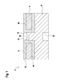
- FIG. 1 is a first embodiment of an inventive device 2 shown in section. This representation is not to scale for clarity.
- the device 2 comprises a component in the form of a printed circuit board 4 and a solid body in the form of a shunt 6.
- the printed circuit board 4 has printed conductors 8, 10, which run along an upper side 12 of the printed circuit board 4 and open into a printed circuit board opening 14. There they extend along the wall of the guide plate opening 14 and exit from this at the bottom 16 of the circuit board 4 again, where they then continue.
- the shunt 6 has an integrally formed with the shunt plug 18 which is inserted into the circuit board opening 14 and is connected thereto by means of a press fit.
- the shapes of the plug 18 and corresponding to the circuit board opening 14 may be round or square in cross-section. In this way, an electrical contact between the conductor tracks 8, 10 and the shunt 6 and a mechanical contact between the circuit board 4 and the shunt 6 is made and maintained.
- the plug 18 can be provided with cutting edges with which it can cut into the material of the printed conductors 8, 10.
- the plug 18 is arranged completely sunk in the printed circuit board opening 14.
- On the upper side of the plug 18, a recess 20 is formed in the shunt 6 inside.
- a recess 22 is formed opposite the plug.
- the electrical contacting can also take place with a solder, not shown, which closes the printed circuit board opening 14 and partially extends over the printed conductors 8, 10 on the surface 12 of the printed circuit board 4.
- the recess 10 is particularly favorable because it provides a wide electrical and mechanical contact surface for the solder.
- the printed conductors 8, 10 do not need to be inserted into the printed circuit board openings 14, since the solder ensures electrical contact with the shunt 6.
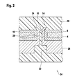
- FIG. 2 a second embodiment of a device 24 according to the invention is shown in section. Identical or functionally identical parts are denoted by the same reference numerals as in the first embodiment. Again, this representation is not to scale for clarity.
- the device 24 of the second exemplary embodiment comprises the printed circuit board 4 with printed conductors 8, 10 and a printed circuit board opening 14.
- the circuit board 4 is placed on a shunt 26 and is supported by these.
- the shunt 26 has a plug 28, which may have the shape of the plug 18 of the first embodiment, is guided through the printed circuit board opening 14 and forms a press fit with this.
- the plug 28 has a through hole 30 through the plug 28 and through the shunt 26.
- a recess 32 is present, which has a larger cross-section than the through hole 30.
- the upper portion 34 of the plug 28 further protrudes beyond the circuit board 4.
- the through-hole 30 can be widened, for example, with a mandrel in order to improve the hold of the printed circuit board 4 at the shunt 26. This widening can also produce the electrical and mechanical contact between shunt 26 and printed circuit board 4 as an alternative to the interference fit.
- the devices 2, 24 of the first and second embodiments may be surrounded by a resilient molding compound 36 which protects the devices 2, 24, for example from contamination.
- a resilient molding compound 36 which protects the devices 2, 24, for example from contamination.
- the recess 20 and the recess 22 or correspondingly through the through hole 30 and the recess 32 the position of the molding compound 36 is fixed.
- the recess 20 of the first embodiment may be designed for a better fixation of the molding compound 36 as a through hole.
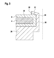
- FIG. 3 is a third embodiment of the device 24 from FIG. 2 shown in section. Identical or functionally identical parts are denoted by the same reference numerals as in the first and second embodiments and will not be described again. Again, this representation is not to scale for clarity.
- the shunt 26 of the device 24 FIG. 2 a plug 29.
- An end region 31 of the plug 29 is bent against the surface 33 of the printed circuit board 4 in such a way (arrow 35) that the end region 31 touches and contacts one of the conductor tracks 8, 10.
- the circuit board 4 is clamped and held between the end portion 31 of the plug 29 and the shunt 26, so that a positive connection is made. Is at the point of contact of the end portion 31 of the connector 29, no trace 8, 10, so the end portion 31 of the connector 29, the surface 33 of the circuit board 4 also touch directly.
- the end portion 31 of the plug 29 can be specially prepared for bending.
- the end portion 31, for example, in the FIG. 3 not shown be protruding from the plug 29 nose.
- the plug 29 of the third embodiment can be used to support the plug 28 FIG. 2 be provided.
- the plug 29 may also electrically contact the printed conductors 8, 10 with the shunt 26 and the printed circuit board 4 with the shunt 26 mechanically. It is also possible that one of the two plugs 28, 29 takes over the electrical contact and the other plug 28, 29 takes over the mechanical contacting.
- the use of the plug 29 from FIG. 3 was related to FIG. 2 described. However, this is not limiting. In the same way, the plug 29 can be made FIG. 3 also together with the plug 18 off FIG. 1 be used to support the electrical and / or mechanical contacting described above.
- the end portion 31 may have one or more protruding lugs or be provided as a circumferential collar.
- FIG. 4 an embodiment of a battery sensor 38 according to the invention is shown in plan view.
- the battery sensor 38 has one of the previously described devices 2, 24.
- the circuit board 4 is shown only in its outlines with five printed circuit board openings 14, through which the plug 18, 28, 29 of the shunt 6 are guided.
- One of the printed circuit board openings 14 is arranged on the edge of the printed circuit board 4 and has a semi-cylindrical shape.
- the plugs 18, 28, 29, the circuit, not shown, of the printed circuit board 4 is electrically connected to the shunt 6 and can thus measure a voltage drop at the shunt 6.
- the volume of the shunt 6 is dimensioned such that the voltage drop is measurably large, but not so large that it leads to an undesirably high loss resistance.
- the current through the shunt 6 and the charge of a battery not shown connected to the shunt 6 can be determined and output, for example, via terminals 40 to a further process unit.
- the area of the shunt 6 is larger in plan view than an area of the circuit board 4.
- the shunt 6 on one side of the circuit has a through hole 42 into which the connector of the battery is inserted.
- the connection can be made with clamps or screw clamps. Alternatively, a further through-hole may also be provided.
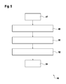
- FIG. 5 is a diagram of an embodiment of a method according to the invention 46 for producing the device 2, 24 according to the invention shown.
- step 48 the printed circuit board 4 is manufactured with the printed circuit board opening 14.
- step 50 the shunt 6, 26 is manufactured with the plug 18, 28.
- step 52 for connecting the shunt 6, 26 to the printed circuit board 4 the plug 18, 28 is inserted into the printed circuit board opening 14, fixed by a frictional connection and made an electrical contact. This completes the process (step 54).
- an integrally formed with the solid body connector is thus provided on an electrically conductive solid body and inserted into a component opening of a component with an electrical circuit.
- the plug for electrical and simultaneous mechanical contacting of the solid body to the component and the circuit can be used.
- the plug and the component can be connected via the component opening positively and / or non-positively, for example by means of a press fit.
Landscapes
- Physics & Mathematics (AREA)
- General Physics & Mathematics (AREA)
- Coupling Device And Connection With Printed Circuit (AREA)
- Details Of Connecting Devices For Male And Female Coupling (AREA)
Abstract
Description
- Die Erfindung betrifft eine elektronische Vorrichtung mit Presspassverbindung, einen Batteriesensor und ein Verfahren zur Herstellung einer derartigen elektronischen Vorrichtung.
- Mit Batteriesensoren wird die Restladung von Batterien bestimmt. Sie sind beispielsweise in
DE 10 2006 019 895 A1 beschrieben. Danach wird der aus der Batterie abfließende elektrische Strom über einen niederohmigen elektrischen Widerstand, auch Nebenschlusswiderstand oder Shunt genannt gemessen, aus dem dann die Restladung der Batterie rechnerisch bestimmt wird. Die Berechnung erfolgt in einer Schaltung auf einer Leiterplatte, die über Verbindungselemente an den Shunt angeschlossen wird. Dabei können die Verbindungselemente sowohl in Bohrungen der Leiterplatte als auch in Bohrungen des Shuntes eingepresst sein. Dieser Aufbau ermöglicht es zwar die Leiterplatte mit dem Shunt gleichzeitig mechanisch und elektrisch sicher zu kontaktieren, ohne dass zur elektrischen Kontaktierung eine größere thermische Beanspruchung der Elemente notwendig wäre, jedoch bedingen die Verbindungselemente für jede Verbindung zwischen Leiterplatte und Shunt zwei verschiedene Kontaktpunke, die einerseits einen erhöhten Fertigungsaufwand bedeuten und andererseits auch den Kontaktwiderstand zwischen Leiterplatte und Shunt erhöhen, der das Messergebnis verfälscht. - Zur Vermeidung dieses doppelten Kontaktes wurde ein Aufbau vorgeschlagen, bei dem die Leiterbahnen wenigstens an der Kontaktstelle zwischen Leiterplatte und Shunt bis auf die Unterseite der Leiterplatte geführt sind und so über eine Lötverbindung mit dem Shunt elektrisch und mechanisch kontaktiert werden können. Dies hat zwar den Vorteil, dass die Leiterplatte über nur noch einen einzigen Kontakt am Shunt kontaktiert werden kann und so die oben genannten Nachteile vermieden werden, der Lötprozess selbst stellt jedoch einige fertigungstechnische Probleme dar. Zunächst müssen die Flächen für die Lötstelle auf dem Shunt und an der Leiterplatte rein sein, da jede Verunreinigung den Kontaktwiderstand erhöht. Der Lötprozess selbst muss genau abgestimmt sein, denn nicht nur Flussmittelreste aus der Lotpaste sondern auch ein übermäßiger Wärmeeintrag können das Produkt schädigen. Auch kann die Leiterplatte beim Löten auf dem Shunt verschwimmen und so deplaziert werden.
- Bei einer elektrischen und mechanischen Verbindung zwischen einer Leiterplatte und einem Shunt ist es somit erwünscht, die Zahl der elektrischen und mechanischen Kontakte pro Verbindung zwischen Leiterplatte und Shunt zu verringern und den Fertigungsprozess so einfach wie möglich zu gestalten.
- Die erfindungsgemäße Vorrichtung ersetzt die Lötstelle aus dem Stand der Technik durch einen einstückig mit dem Shunt ausgebildeten Stecker. Der Vorteil der Erfindung ist, dass ein Verschwimmen und damit eine Deplatzierung der Leiterplatte auf dem Shunt durch den Lötprozess ausgeschlossen sind. Jede Verbindung zwischen Leiterplatte und Shunt benötigt trotzdem nur einen einzigen Kontakt, der gleichzeitig die mechanische und die elektrische Verbindung zwischen Leiterplatte und Shunt gewährleistet. So wird nicht nur der ohmsche elektrische Kontaktwiderstand zwischen Leiterplatte und Shunt sondern auch die Zahl der notwendigen Fertigungsschritte bei der Herstellung verringert, da nicht nur weniger Arbeitsschritte zum Kontaktieren selbst sondern auch weniger vorzufertigende Bauteile notwendig sind. Die erfindungsgemäße Vorrichtung umfasst ein Bauteil mit einem elektrischen Schaltkreis und einer Bauteilöffnung sowie einen elektrisch leitfähigen Massivkörper, der einen einstückig mit dem Massivkörper ausgebildeten Stecker aufweist, über den der Massivkörper und der Schaltkreis in elektrischem Kontakt miteinander stehen. Dabei sind der Stecker und das Bauteil über die Bauteilöffnung mittels einer kraft- und/oder formschlüssigen Verbindung miteinander verbunden.
- Die Unteransprüche zeigen bevorzugte Weiterbildungen der Erfindung.
- In einer bevorzugten Ausführung der Erfindung kann die kraftschlüssige Verbindung eine Presspassung in der Bauteilöffnung zwischen dem Stecker und dem Bauteil sein. Auf diese Weise ist die Verbindung dauerhaft beständig selbst gegen höhere Belastungen. Ferner wird gleichzeitig ein sicherer elektrischer Kontakt gewährleistet.
- In einer weiteren bevorzugten Ausführungsform der Erfindung kann die Bauteilöffnung durchgehend durch das Bauteil ausgebildet sein, so dass die Pressverbindung keine Spannungen auf die Oberfläche des Bauteils auf der gegenüberliegenden Seite der Bauteilöffnung aufbauen kann.
- In einer alternativen oder zusätzlichen Ausbildung der Erfindung kann für die formschlüssige Verbindung ein Endbereich des Steckers derart angeordnet sein, dass der Endbereich eine Oberfläche des Bauteils berührt. Auf diese Weise kann die elektrische Verbindung zwischen Leiterplatte und Shunt einfach durch umbiegen und Kontaktieren des Endbereichs des Steckers mit dem Schaltkreis erreicht werden.
- In einer weiteren bevorzugten Ausführung der Erfindung kann der Stecker an seiner Stirnseite eine Vertiefung aufweisen. Mittels der Vertiefung kann vorzugsweise noch ein Verstemmen des Steckers an der Bauteilöffnung erfolgen. Soll der Stecker über eine optionale Lötverbindung an eine Leiterbahn des Schaltkreises kontaktiert werden, so bietet die Vertiefung eine zusätzliche Fläche, um den Kontakt zwischen Lot und Stecker mechanisch beständiger und elektrisch niederohmiger auszugestalten.
- Diese Vertiefung kann in einer Weiterbildung der Erfindung eine Durchgangsöffnung durch den Massivkörper sein und so zur Senkung von Spannungen im Massivkörper beitragen. Alternativ ist die Vertiefung ein Sackloch.
- Die Durchgangsöffnung kann sich in einer weiteren Weiterbildung der Erfindung insbesondere von einer dem Stecker gegenüberliegenden Seite des Massivkörpers aus verjüngen. Auf diese Weise bietet die Durchgangsöffnung einen guten Halt für die elastische Gussmasse.
- In einer anderen Ausbildung der Erfindung kann die Vertiefung an der Stirnseite des Steckers aufgeweitet sein. Dies würde eine alternative oder zusätzliche Befestigungsmöglichkeit des Bauteils am Massivkörper über den Stecker bieten. Insbesondere könnte das Bauteil so doppelt abgesichert werden, so dass sich das Bauteil selbst bei einer fehlerhaft gefertigten Presspassung nicht vom Massivkörper löst.
- Der Massivkörper kann einen elektrischen Nebenschlusswiderstand für den Schaltkreis aufweisen und so nicht nur als Halteelement dienen sondern auch eine Funktion als elektrisches Bauteil übernehmen.
- In einer besonderen Ausbildung kann in der Draufsicht auf die Vorrichtung eine Fläche des Massivkörpers gleich groß oder größer sein, als eine Fläche des Bauteils. Die Dimension des Massivkörpers ist so ausreichend groß, um ihn in Reihe zwischen einem Batteriepol und einem Verbraucher als Stromaufnehmer zur Messung des aus der Batterie abgegebenen Stromes zu nutzen, so dass eine messbare Spannung abfällt, ohne spürbar großen Verlustleistungen zu erzeugen.
- In einer anderen Ausführung der Erfindung kann der Stecker einen dreieckigen, viereckigen oder runden Querschnitt aufweisen. Ein Stecker mit eckigem Querschnitt sichert die Lage des Massivkörpers gegen das Bauteil auch gegen ein Verdrehen beider Elemente zueinander, während sich ein Stecker mit einem runden Querschnitt durch Drehbewegungen gut in die Bauteilöffnungen einführen lässt.
- In die Vertiefung kann in einer vorteilhaften Ausbildung eine elastische Gussmasse eingegossen sein und so die Verbindungsstelle zwischen Massivkörper und Bauteil vor Verunreinigungen schützen.
- In einer zusätzlichen oder alternativen Weiterbildung der Erfindung können der Massivkörper mit dem Stecker und das elektrische Bauteil wenigstens teilweise oder vollständig von der elastischen Gussmasse umgeben sein. Auf diese kann der Schutz vor Verunreinigungen von wichtigen Bauteilen bis auf die gesamte Vorrichtung hin ausgedehnt werden.
- In einer alternativen oder zusätzlichen Ausbildung können der Stecker und/oder die Bauteilöffnung mit Schneiden versehen sein. Diese verbessert die elektrische Kontaktierung mit dem Bauteil in der Bauteilöffnung.
- In einer bevorzugten Ausführungsform der Erfindung kann die Leiterbahn des Schaltkreises, die mit dem Shunt zu kontaktieren ist, in die Bauteilöffnung eingeführt sein. Dies hat den Vorteil, dass in Verbindung mit der Presspassung der Prozess des Lötens und Reinigens komplett entfällt. Auch die Flussmittelreste aus der Lötpaste und ein übermäßiger Wärmeeintrag auf das Produkt entfallen. Das Lot wird nicht benötigt. Somit kann auch keine stoffschlüssige Verbindungslücke zwischen Lot und der Kontaktstellen auf dem Shunt und/oder der Leiterplatte, sogenannte kalte Lötstellen entstehen.
- Die Erfindung gibt auch einen elektronischen Batteriesensor an, der eine erfindungsgemäße Vorrichtung umfasst. Dabei kann der Massivkörper einen Nebenschlusswiderstand aufweisen und der Schaltkreis einen Ladestand einer mit dem elektronischen Batteriesensor verbundenen Batterie basierend auf einem erfassten elektrischen Strom durch den Nebenschlusswiderstand bestimmen. Ein derartiger Batteriesensor ist durch die robuste mechanische und elektrische Verbindung zwischen Massivkörper und Bauteil sehr ausfallsicher selbst bei extremen Erschütterungen. Daher ist der erfindungsgemäße elektronische Batteriesensor hervorragend zum Messen des Ladestandes einer Kraftfahrzeugbatterie selbst während der Fahrt geeignet.
- Die Erfindung gibt auch ein Verfahren zum Herstellen einer Vorrichtung an, die einen elektrisch leitfähigen Massivkörper und ein Bauteil mit einem elektrischen Schaltkreis und einer Bauteilöffnung umfasst. In diesem Verfahren wird zunächst das den Schaltkreis tragende Bauteil mit der Bauteilöffnung und dann der Massivkörpers mit einem einstückig vom Massivkörper vorstehenden Stecker ausgebildet. Schließlich wird das Bauteil mit dem Massivkörper über eine kraftschlüssige Verbindung, insbesondere Pressverbindung und/oder über eine formschlüssige Verbindung zwischen dem Bauteil und dem Stecker über die Bauteilöffnung verbunden. Vorteilhaft an diesem Herstellungsverfahren ist, dass der Stecker parallel bei der Herstellung des Shunts angefertigt werden kann, was insbesondere in der Massenproduktion wichtige Prozesszeit einspart.
- Nachfolgend werden den Schutzbereich nicht einschränkende Ausführungsbeispiele der Erfindung unter Bezugnahme auf die begleitenden Zeichnungen im Detail beschrieben. In der Zeichnung ist:
- Figur 1
- eine Schnittdarstellung eines ersten Ausführungsbeispiels für eine erfindungsgemäße Vorrichtung;
- Figur 2
- eine Schnittdarstellung eines zweiten Ausführungsbeispiel für eine erfindungsgemäße Vorrichtung;
- Figur 3
- eine Schnittdarstellung eines dritten Ausführungsbeispiel für eine erfindungsgemäße Vorrichtung;
- Figur 4
- eine Darstellung eines Ausführungsbeispiel für einen erfindungsgemäßen Batteriesensor in der Draufsicht; und
- Figur 5
- ein Ablaufdiagramm eines Ausführungsbeispiel für ein erfindungsgemäßes Verfahren.
- In
Figur 1 ist ein erstes Ausführungsbeispiel für eine erfindungsgemäße Vorrichtung 2 im Schnitt dargestellt. Diese Darstellung ist zum besseren Verständnis nicht maßstabsgetreu. Die Vorrichtung 2 umfasst ein Bauteil in Form einer Leiterplatte 4 und einen Massivkörper in Form eines Shunts 6. - Die Leiterplatte 4 weist Leiterbahnen 8, 10 auf, die entlang einer Oberseite 12 der Leiterplatte 4 verlaufen und in eine Leiterplattenöffnung 14 münden. Dort erstrecken Sie sich entlang der Wand der Leitplattenöffnung 14 und treten aus dieser an der Unterseite 16 der Leiterplatte 4 wieder aus, wo sie dann weiterverlaufen.
- Der Shunt 6 weist einen einstückig mit dem Shunt ausgebildeten Stecker 18 auf, der in die Leiterplattenöffnung 14 eingeführt ist und mit dieser mittels einer Presspassung verbunden ist. Die Formen des Steckers 18 und entsprechend der Leiterplattenöffnung 14 können im Querschnitt rund oder eckig sein. Auf diese Weise wird ein elektrischer Kontakt zwischen den Leiterbahnen 8, 10 und dem Shunt 6 sowie ein mechanischer Kontakt zwischen der Leiterplatte 4 und dem Shunt 6 hergestellt und gehalten. Um den Kontakt zwischen Shunt 6 und Leiterbahnen 8, 10 zu verbessern kann der Stecker 18 mit Schneiden versehen sein, mit denen er sich in das Material der Leiterbahnen 8, 10 hineinschneiden kann. Der Stecker 18 ist in der Leiterplattenöffnung 14 vollständig versenkt angeordnet. Auf der Oberseite des Steckers 18 ist eine Vertiefung 20 in den Shunt 6 hinein ausgebildet. Auf der Unterseite des Shunts 6 ist gegenüber dem Stecker eine Ausnehmung 22 ausgebildet.
- Zur weiteren Sicherung der Presspassung kann insbesondere die elektrische Kontaktierung auch mit einem nicht gezeigten Lot erfolgen, das die Leiterplattenöffnung 14 verschließt und sich teilweise über die Leiterbahnen 8, 10 auf der Oberfläche 12 der Leiterplatte 4 erstreckt. In diesem Fall ist die Vertiefung 10 besonders günstig, da sie eine breite elektrische und mechanische Kontaktfläche für das Lot bietet. Auch brauchen in diesem Fall die Leiterbahnen 8, 10 nicht in die Leiterplattenöffnungen 14 eingeführt zu werden, da das Lot die elektrische Kontaktierung zum Shunt 6 sicherstellt.
- In
Figur 2 ist ein zweites Ausführungsbeispiel für eine erfindungsgemäße Vorrichtung 24 im Schnitt dargestellt. Gleiche beziehungsweise funktional gleiche Teile sind mit den gleichen Bezugszeichen wie im ersten Ausführungsbeispiel bezeichnet. Auch diese Darstellung ist zur verständlicheren Darstellung nicht maßstabgetreu. Die Vorrichtung 24 des zweiten Ausführungsbeispiels umfasst die Leiterplatte 4 mit Leiterbahnen 8, 10 und einer Leiterplattenöffnung 14. - Die Leiterplatte 4 ist auf einen Shunt 26 aufgesetzt und wird von diesen getragen. Der Shunt 26 weist einen Stecker 28 auf, der die Form des Steckers 18 des ersten Ausführungsbeispiels aufweisen kann, durch die Leiterplattenöffnung 14 geführt ist und mit dieser eine Presspassung bildet. Der Stecker 28 weist eine Durchgangsbohrung 30 durch den Stecker 28 und durch den Shunt 26 auf. Am Shunt 26 auf der gegenüberliegenden Seite des Steckers 28 ist eine Ausnehmung 32 vorhanden, die einen größeren Querschnitt als die Durchgangsbohrung 30 aufweist. Der obere Bereich 34 des Steckers 28 ragt ferner über die Leiterplatte 4 hinaus. In diesem Bereich 34 kann die Durchgangsbohrung 30 beispielsweise mit einem Dorn aufgeweitet werden, um den Halt der Leiterplatte 4 am Shunt 26 zu verbessern. Diese Aufweitung kann auch alternativ zur Presspassung die elektrische und mechanische Kontaktierung zwischen Shunt 26 und Leiterplatte 4 herstellen.
- Wie beispielhaft in der
Figur 2 gezeigt, können die Vorrichtungen 2, 24 des ersten und zweiten Ausführungsbeispiels von einer elastischen Gussmasse 36 umgeben sein, die die Vorrichtungen 2, 24 beispielsweise vor Verschmutzung schützt. Durch die Vertiefung 20 und die Ausnehmung 22 oder entsprechend durch die Durchgangsbohrung 30 und die Ausnehmung 32 wird die Lage der Gussmasse 36 fixiert. Auch kann die Vertiefung 20 des ersten Ausführungsbeispiels für eine bessere Fixierung der Gussmasse 36 als Durchgangsbohrung ausgeführt sein. - In
Figur 3 ist ein drittes Ausführungsbeispiel für die Vorrichtung 24 ausFigur 2 im Schnitt dargestellt. Gleiche beziehungsweise funktional gleiche Teile sind mit den gleichen Bezugszeichen wie im ersten und zweiten Ausführungsbeispiel bezeichnet und werden nicht noch einmal beschrieben. Auch diese Darstellung ist zur verständlicheren Darstellung nicht maßstabgetreu. - Im dritten Ausführungsbeispiel weist der Shunt 26 der Vorrichtung 24 aus
Figur 2 einen Stecker 29 auf. Ein Endbereich 31 des Steckers 29 ist gegen die Oberfläche 33 der Leiterplatte 4 derart gebogen (Pfeil 35), dass der Endbereich 31 eine der Leiterbahnen 8, 10 berührt und kontaktiert. Auf diese Weise wird die Leiterplatte 4 zwischen dem Endbereich 31 des Steckers 29 und dem Shunt 26 eingeklemmt und gehalten, so dass eine formschlüssige Verbindung hergestellt ist. Ist an der Berührungsstelle des Endbereichs 31 des Steckers 29 keine Leiterbahn 8, 10 vorhanden, so kann der Endbereich 31 des Steckers 29 die Oberfläche 33 der Leiterplatte 4 auch direkt berühren. - Der Endbereich 31 des Steckers 29 kann zum Biegen speziell vorbereitet werden. Dazu kann der Endbereich 31 beispielsweise eine in der
Figur 3 nicht gezeigte vom Stecker 29 abragende Nase sein. - Der Stecker 29 des dritten Ausührungsbeispiels kann zur Unterstützung des Steckers 28 aus
Figur 2 vorgesehen sein. Alternativ kann der Stecker 29 auch allein die Leiterbahnen 8, 10 mit dem Shunt 26 elektrisch sowie die Leiterplatte 4 mit dem Shunt 26 mechanisch kontaktieren. Es ist ebenfalls möglich, dass einer der beiden Stecker 28, 29 die elektrische Kontaktierung und der andere Stecker 28, 29 die mechanische Kontaktierung übernimmt. - Die Verwendung des Steckers 29 aus
Figur 3 wurde im Zusammenhang mitFigur 2 beschrieben. Dies ist jedoch nicht einschränkend. In gleicher Weise kann der Stecker 29 ausFigur 3 auch zusammen mit dem Stecker 18 ausFigur 1 zur Unterstützung der zuvor beschriebenen elektrischen und/oder mechanischen Kontaktierung verwendet werden. Der Endbereich 31 kann eine oder mehrere vorstehende Nasen aufweisen oder als umlaufender Kragen vorgesehen werden. - In
Figur 4 ist ein Ausführungsbeispiel für einen erfindungsgemäßen Batteriesensor 38 in der Draufsicht dargestellt. - Der Batteriesensor 38 weist eine der zuvor beschriebenen Vorrichtungen 2, 24 auf. Die Leiterplatte 4 ist dabei nur in ihren Umrissen mit fünf Leiterplattenöffnungen 14 dargestellt, durch welche die Stecker 18, 28, 29 des Shunts 6 geführt sind. Eine der Leiterplattenöffnungen 14 ist dabei am Rand der Leiterplatte 4 angeordnet und weist eine halbzylindrische Form auf. Durch die Stecker 18, 28, 29 wird der nicht gezeigte Schaltkreis der Leiterplatte 4 elektrisch mit dem Shunt 6 verbunden und kann so einen Spannungsabfall am Shunt 6 messen. Das Volumen des Shunts 6 ist so dimensioniert, dass der Spannungsabfall zwar messbar groß, jedoch nicht so groß wird dass er zu einem unerwünscht hohen Verlustwiderstand führt. Mit diesem Spannungsabfall kann schließlich der Strom durch den Shunt 6 und die Ladung einer an den Shunt 6 angeschlossenen nicht gezeigten Batterie bestimmt und beispielsweise über Anschlüsse 40 an eine weitere Prozesseinheit ausgegeben werden. Die Fläche des Shunts 6 ist in der Draufsicht größer als eine Fläche der Leiterplatte 4.
- Zum Anschluss an die Batterie weist der Shunt 6 an einer Seite neben der Schaltung eine Durchgangsbohrung 42 auf, in die der Anschlussstecker der Batterie eingeführt wird. Auf der anderen Seite 44 des Shunts kann dann ein nicht gezeigter Verbraucher angeschlossen werden. Der Anschluss kann mit Klemmen oder Schraubzwingen erfolgen. Alternativ kann auch eine weitere Durchgangsbohrung vorgesehen sein.
- In
Figur 5 ist ein Diagramm eines Ausführungsbeispiels für ein erfindungsgemäßes Verfahren 46 zur Herstellung der erfindungsgemäßen Vorrichtung 2, 24 dargestellt. - Danach wird nach dem Start 47 zunächst im ersten Schritt 48 die Leiterplatte 4 mit der Leiterplattenöffnung 14 gefertigt. Im zweiten Schritt 50 wird der Shunt 6, 26 mit dem Stecker 18, 28 gefertigt. Die Reihenfolge der Schritte 48 und 50 ist beliebig austauschbar. Schließlich wird im Schritt 52 zum Verbinden des Shunts 6, 26 mit der Leiterplatte 4 der Stecker 18, 28 in die Leiterplattenöffnung 14 eingeführt, durch eine kraftschlüssige Verbindung fixiert und ein elektrischer Kontakt hergestellt. Damit ist das Verfahren beendet (Schritt 54).
- In allen beschriebenen Ausführungsbeispielen wird somit an einem elektrisch leitfähigen Massivkörper ein einstückig mit dem Massivkörper ausgebildeter Stecker vorgesehen und in eine Bauteilöffnung eines Bauteils mit einem elektrischen Schaltkreis eingeführt. Auf diese Weise kann der Stecker zur elektrischen und gleichzeitigen mechanischen Kontaktierung des Massivkörpers an das Bauteil und den Schaltkreis verwendet werden. Der Stecker und das Bauteil können über die Bauteilöffnung formschlüssig und/oder kraftschlüssig beispielsweise mittels einer Presspassung verbunden sein.
Claims (15)
- Vorrichtung umfassend:- ein Bauteil (4) mit einem elektrischen Schaltkreis (8, 10) und einer Bauteilöffnung (14) und- einen elektrisch leitfähigen Massivkörper (6, 26), der einen einstückig mit dem Massivkörper (6, 26) ausgebildeten Stecker (18, 28) aufweist, über den der Massivkörper (6, 26) und der Schaltkreis (8, 10) in elektrischem Kontakt miteinander stehen,- wobei der Stecker (18, 28, 29) und das Bauteil (4) über die Bauteilöffnung (14) mittels einer kraft- und/oder formschlüssigen Verbindung verbunden sind.
- Vorrichtung nach Anspruch 1, wobei die kraftschlüssige Verbindung eine Presspassung in der Bauteilöffnung (14) zwischen dem Stecker (18, 28) und dem Bauteil (4) ist.
- Vorrichtung nach einem der vorstehenden Ansprüche, wobei die Bauteilöffnung (14) durchgehend durch das Bauteil (4) ausgebildet ist.
- Vorrichtung nach Anspruch 3, wobei für die formschlüssige Verbindung ein Endbereich (31) des Steckers (29) derart angeordnet ist, dass der Endbereich eine Oberfläche des Bauteils (4) berührt.
- Vorrichtung nach einem der vorstehenden Ansprüche, wobei der Stecker (18, 28, 29) an seiner Stirnseite eine Vertiefung (20, 30) aufweist.
- Vorrichtung nach Anspruch 5, wobei die Vertiefung (20, 30) eine Durchgangsöffnung (30) durch den Massivkörper (6, 26) ist.
- Vorrichtung nach Anspruch 6, wobei die Durchgangsöffnung (30) sich verjüngend, insbesondere von einer dem Stecker (18, 28) gegenüberliegenden Seite des Massivkörpers (6, 26) aus, vorgesehen ist.
- Vorrichtung nach einem der Ansprüche 5 bis 7, wobei die Vertiefung (20, 30) an der Stirnseite des Steckers aufgeweitet ist.
- Vorrichtung nach einem der Ansprüche 5 bis 8 umfassend eine in die Vertiefung (20, 30) eingegossene elastische Gussmasse (36).
- Vorrichtung nach Anspruch 9, wobei der Massivkörper (6, 26) mit dem Stecker (18, 28) und das elektrische Bauteil (4) wenigstens teilweise von der elastischen Gussmasse (36) umgeben sind.
- Vorrichtung nach einem der vorstehenden Ansprüche, wobei der Massivkörper (6, 26) ein elektrischer Nebenschlusswiderstand für den Schaltkreis ist.
- Vorrichtung nach einem der vorstehenden Ansprüche, wobei in der Draufsicht auf die Vorrichtung (2, 24) eine Fläche des Massivkörpers (6, 26) gleich groß oder größer ist, als eine Fläche des Bauteils (4).
- Vorrichtung nach einem der vorstehenden Ansprüche, wobei der Stecker (18, 28) eine Volumenform mit Schneidcharakter aufweist.
- Elektronischer Batteriesensor umfassend- eine Vorrichtung (2, 24) nach einem der vorstehenden Ansprüche, wobei- der Massivkörper (6, 26) einen Nebenschlusswiderstand aufweist und- der Schaltkreis (8, 10) zum Bestimmen eines Ladestandes einer mit dem elektronischen Batteriesensor (38) verbundenen Batterie basierend auf einem erfassten elektrischen Strom durch den Nebenschlusswiderstand vorgesehen ist.
- Verfahren zum Herstellen einer Vorrichtung (2, 24) umfassend einen elektrisch leitfähigen Massivkörper (6, 26) und ein Bauteil (4) mit einem elektrischen Schaltkreis (8, 10) und einer Bauteilöffnung (14) mit den Schritten:- Ausbilden (48) des den Schaltkreis (8, 10) tragenden Bauteils (4) mit der Bauteilöffnung (14);- Ausbilden (50) des Massivkörpers (6, 26) mit einem einstückig vom Massivkörper (6, 26) vorstehenden Stecker (18, 28); und- Verbinden (52) des Bauteils (4) mit dem Massivkörper (6, 26) über eine kraftschlüssige Verbindung, insbesondere Pressverbindung und/oder über eine formschlüssige Verbindung zwischen dem Bauteil (4) und dem Stecker (18, 28, 29) über die Bauteilöffnung (14).
Applications Claiming Priority (1)
| Application Number | Priority Date | Filing Date | Title |
|---|---|---|---|
| DE102010028381A DE102010028381A1 (de) | 2010-04-29 | 2010-04-29 | Elektronische Vorrichtung mit Presspassverbindung |
Publications (3)
| Publication Number | Publication Date |
|---|---|
| EP2383842A2 true EP2383842A2 (de) | 2011-11-02 |
| EP2383842A3 EP2383842A3 (de) | 2011-11-09 |
| EP2383842B1 EP2383842B1 (de) | 2014-12-31 |
Family
ID=44263063
Family Applications (1)
| Application Number | Title | Priority Date | Filing Date |
|---|---|---|---|
| EP11163843.3A Not-in-force EP2383842B1 (de) | 2010-04-29 | 2011-04-27 | Elektronische Vorrichtung mit Presspassverbindung |
Country Status (2)
| Country | Link |
|---|---|
| EP (1) | EP2383842B1 (de) |
| DE (1) | DE102010028381A1 (de) |
Citations (1)
| Publication number | Priority date | Publication date | Assignee | Title |
|---|---|---|---|---|
| DE102006019895A1 (de) | 2006-04-28 | 2007-11-15 | Siemens Ag | Strommessvorrichtung mit speziell kontaktierter Leiterplatte und entsprechendes Herstellungsverfahren |
Family Cites Families (15)
| Publication number | Priority date | Publication date | Assignee | Title |
|---|---|---|---|---|
| GB776153A (en) * | 1953-11-23 | 1957-06-05 | Enfield Cables Ltd | Improvements in electrical connecting plugs |
| US4275374A (en) * | 1979-08-20 | 1981-06-23 | Daniel Chaucer | Fuse-plug adapter for electrical cord |
| DE9311221U1 (de) * | 1993-07-27 | 1993-11-18 | Siemens AG, 80333 München | Verbindung eines Antennendrahtes mit einer Leiterplatte eines Mobilteils von einem schnurlosen Telefon |
| JP2901900B2 (ja) * | 1995-08-04 | 1999-06-07 | エス・オー・シー株式会社 | コード付き電源プラグ |
| US5941735A (en) * | 1996-06-12 | 1999-08-24 | Litton Systems, Inc. | Press-fit fuse or component holder |
| JPH1083753A (ja) * | 1996-09-05 | 1998-03-31 | Yazaki Corp | サービスプラグ |
| DE102004007851B4 (de) * | 2004-02-17 | 2006-03-16 | Kromberg & Schubert Gmbh & Co. Kg | Anschlussvorrichtung für eine Batterie |
| DE102004053648A1 (de) * | 2004-11-03 | 2006-05-04 | Leopold Kostal Gmbh & Co. Kg | Batteriestromsensor für ein Kraftfahrzeug |
| DE102004055849A1 (de) * | 2004-11-19 | 2006-06-01 | Bayerische Motoren Werke Ag | Batteriesensorvorrichtung |
| FR2879751B1 (fr) * | 2004-12-20 | 2007-02-23 | Johnson Controls Tech Co | Dispositif de mesure d'un courant circulant dans un cable |
| DE202005013220U1 (de) * | 2005-08-19 | 2005-12-22 | Wagon Automotive Gmbh | Blechformteil mit Durchsetzfügeverbindungen |
| DE102005057117A1 (de) * | 2005-11-30 | 2007-06-14 | Siemens Ag | Vorrichtung zum Erfassen einer elektrischen Größe eines Akkumulators und Verfahren zur Herstellung derselbigen |
| US7381101B2 (en) * | 2006-08-25 | 2008-06-03 | Lear Corporation | Battery post connector |
| DE102008041539A1 (de) * | 2008-08-26 | 2010-03-04 | Robert Bosch Gmbh | Shuntwiderstand mit Auswerteschaltung |
| DE102009000827A1 (de) * | 2009-02-13 | 2010-08-19 | Robert Bosch Gmbh | Vorrichtung und Verfahren zum Verbinden zumindest zwei elektrischer Anschlüsse |
-
2010
- 2010-04-29 DE DE102010028381A patent/DE102010028381A1/de not_active Withdrawn
-
2011
- 2011-04-27 EP EP11163843.3A patent/EP2383842B1/de not_active Not-in-force
Patent Citations (1)
| Publication number | Priority date | Publication date | Assignee | Title |
|---|---|---|---|---|
| DE102006019895A1 (de) | 2006-04-28 | 2007-11-15 | Siemens Ag | Strommessvorrichtung mit speziell kontaktierter Leiterplatte und entsprechendes Herstellungsverfahren |
Also Published As
| Publication number | Publication date |
|---|---|
| DE102010028381A1 (de) | 2011-11-03 |
| EP2383842B1 (de) | 2014-12-31 |
| EP2383842A3 (de) | 2011-11-09 |
Similar Documents
| Publication | Publication Date | Title |
|---|---|---|
| EP2274749B1 (de) | Elektronisches bauelement und entsprechendes herstellungsverfahren | |
| DE102004007851B4 (de) | Anschlussvorrichtung für eine Batterie | |
| DE112012000136B4 (de) | Mangan-Kupfer-Shunt gegen elektromagnetische Wechselfelder | |
| DE102004006298B4 (de) | Verbindungsanordnung für ein Messelement eines Batteriesensors | |
| WO2012019784A1 (de) | Strommesswiderstand | |
| EP3433897B1 (de) | Deckel für ein gehäuse, batteriesensor und verfahren zum herstellen eines batteriesensors | |
| DE102015115264B3 (de) | Zentrierhalteeinrichtung für eine Rogowski-Spule, Messeinrichtung, Leistungselektronikeinrichtung und ein Verfahren zur Anordnung einer Rogowski-Spule | |
| DE102007009569B4 (de) | Anschlusseinrichtung und Verfahren zu deren Herstellung | |
| DE102007020882A1 (de) | Einrichtung zur Überprüfung der Befestigung einer Leiterbahnplatte an einem Träger | |
| DE102015216789A1 (de) | Anschlussvorrichtung zum Anschließen eines Messgerätes an einen Anschlusspol eines Energiespeichers eines Kraftfahrzeugs | |
| DE202021105281U1 (de) | Strommesswiderstand | |
| EP1858034A1 (de) | Elektrisches Potentiometer | |
| EP2800168B1 (de) | Batteriesystem und Verfahren zur Herstellung einer elektrisch leitenden Verbindung zwischen einem Zellverbinder und einer Elektronikeinheit eines Batteriesystems | |
| DE202010010152U1 (de) | Strommessmodul | |
| DE102008006866A1 (de) | Vorrichtung zur Strommessung | |
| WO2013139547A1 (de) | Elektronischer batteriesensor | |
| DE102015218796A1 (de) | Batteriesensoreinheit mit integriertem Widerstandselement | |
| DE102015216700A1 (de) | Anschlussvorrichtung zum Anschließen eines Messgerätes an einen Anschlusspol eines Energiespeichers eines Kraftfahrzeugs | |
| DE102007006050B4 (de) | Anschlusseinrichtung | |
| DE102008022973A1 (de) | Elektrische Verbindung mit mindestens zwei Bauteilen | |
| EP2383842B1 (de) | Elektronische Vorrichtung mit Presspassverbindung | |
| DE102021122751B4 (de) | Leiterplattenanordnung zur messung eines batteriestroms eines batteriebetriebenen fahrzeugs | |
| DE102004040575A1 (de) | Einrichtung zum Messen von elektrischem Strom, Spannung und Temperatur an einem aus starrem Material bestehenden elektrischen Leiter | |
| DE202017107108U1 (de) | Hochvolt-Buchsenkontakt mit zwei indentischen Kontaktteilen und elektrische Steckverbindung mit einem Hochvolt-Buchsenkontakt | |
| DE102007017730A1 (de) | Sensorvorrichtung |
Legal Events
| Date | Code | Title | Description |
|---|---|---|---|
| PUAL | Search report despatched |
Free format text: ORIGINAL CODE: 0009013 |
|
| AK | Designated contracting states |
Kind code of ref document: A2 Designated state(s): AL AT BE BG CH CY CZ DE DK EE ES FI FR GB GR HR HU IE IS IT LI LT LU LV MC MK MT NL NO PL PT RO RS SE SI SK SM TR |
|
| AX | Request for extension of the european patent |
Extension state: BA ME |
|
| AK | Designated contracting states |
Kind code of ref document: A3 Designated state(s): AL AT BE BG CH CY CZ DE DK EE ES FI FR GB GR HR HU IE IS IT LI LT LU LV MC MK MT NL NO PL PT RO RS SE SI SK SM TR |
|
| AX | Request for extension of the european patent |
Extension state: BA ME |
|
| RIC1 | Information provided on ipc code assigned before grant |
Ipc: H01R 11/28 20060101AFI20110930BHEP |
|
| PUAI | Public reference made under article 153(3) epc to a published international application that has entered the european phase |
Free format text: ORIGINAL CODE: 0009012 |
|
| 17P | Request for examination filed |
Effective date: 20120509 |
|
| 17Q | First examination report despatched |
Effective date: 20140305 |
|
| GRAP | Despatch of communication of intention to grant a patent |
Free format text: ORIGINAL CODE: EPIDOSNIGR1 |
|
| RIN1 | Information on inventor provided before grant (corrected) |
Inventor name: GRAUF, GERHARD |
|
| INTG | Intention to grant announced |
Effective date: 20141008 |
|
| GRAS | Grant fee paid |
Free format text: ORIGINAL CODE: EPIDOSNIGR3 |
|
| GRAA | (expected) grant |
Free format text: ORIGINAL CODE: 0009210 |
|
| AK | Designated contracting states |
Kind code of ref document: B1 Designated state(s): AL AT BE BG CH CY CZ DE DK EE ES FI FR GB GR HR HU IE IS IT LI LT LU LV MC MK MT NL NO PL PT RO RS SE SI SK SM TR |
|
| REG | Reference to a national code |
Ref country code: CH Ref legal event code: EP Ref country code: GB Ref legal event code: FG4D Free format text: NOT ENGLISH |
|
| REG | Reference to a national code |
Ref country code: IE Ref legal event code: FG4D Free format text: LANGUAGE OF EP DOCUMENT: GERMAN |
|
| REG | Reference to a national code |
Ref country code: DE Ref legal event code: R096 Ref document number: 502011005446 Country of ref document: DE Effective date: 20150212 |
|
| REG | Reference to a national code |
Ref country code: AT Ref legal event code: REF Ref document number: 704879 Country of ref document: AT Kind code of ref document: T Effective date: 20150215 |
|
| PG25 | Lapsed in a contracting state [announced via postgrant information from national office to epo] |
Ref country code: LT Free format text: LAPSE BECAUSE OF FAILURE TO SUBMIT A TRANSLATION OF THE DESCRIPTION OR TO PAY THE FEE WITHIN THE PRESCRIBED TIME-LIMIT Effective date: 20141231 Ref country code: FI Free format text: LAPSE BECAUSE OF FAILURE TO SUBMIT A TRANSLATION OF THE DESCRIPTION OR TO PAY THE FEE WITHIN THE PRESCRIBED TIME-LIMIT Effective date: 20141231 Ref country code: NO Free format text: LAPSE BECAUSE OF FAILURE TO SUBMIT A TRANSLATION OF THE DESCRIPTION OR TO PAY THE FEE WITHIN THE PRESCRIBED TIME-LIMIT Effective date: 20150331 |
|
| REG | Reference to a national code |
Ref country code: NL Ref legal event code: VDEP Effective date: 20141231 |
|
| REG | Reference to a national code |
Ref country code: LT Ref legal event code: MG4D |
|
| PG25 | Lapsed in a contracting state [announced via postgrant information from national office to epo] |
Ref country code: SE Free format text: LAPSE BECAUSE OF FAILURE TO SUBMIT A TRANSLATION OF THE DESCRIPTION OR TO PAY THE FEE WITHIN THE PRESCRIBED TIME-LIMIT Effective date: 20141231 Ref country code: HR Free format text: LAPSE BECAUSE OF FAILURE TO SUBMIT A TRANSLATION OF THE DESCRIPTION OR TO PAY THE FEE WITHIN THE PRESCRIBED TIME-LIMIT Effective date: 20141231 Ref country code: GR Free format text: LAPSE BECAUSE OF FAILURE TO SUBMIT A TRANSLATION OF THE DESCRIPTION OR TO PAY THE FEE WITHIN THE PRESCRIBED TIME-LIMIT Effective date: 20150401 Ref country code: LV Free format text: LAPSE BECAUSE OF FAILURE TO SUBMIT A TRANSLATION OF THE DESCRIPTION OR TO PAY THE FEE WITHIN THE PRESCRIBED TIME-LIMIT Effective date: 20141231 Ref country code: RS Free format text: LAPSE BECAUSE OF FAILURE TO SUBMIT A TRANSLATION OF THE DESCRIPTION OR TO PAY THE FEE WITHIN THE PRESCRIBED TIME-LIMIT Effective date: 20141231 |
|
| PG25 | Lapsed in a contracting state [announced via postgrant information from national office to epo] |
Ref country code: NL Free format text: LAPSE BECAUSE OF FAILURE TO SUBMIT A TRANSLATION OF THE DESCRIPTION OR TO PAY THE FEE WITHIN THE PRESCRIBED TIME-LIMIT Effective date: 20141231 |
|
| PG25 | Lapsed in a contracting state [announced via postgrant information from national office to epo] |
Ref country code: CZ Free format text: LAPSE BECAUSE OF FAILURE TO SUBMIT A TRANSLATION OF THE DESCRIPTION OR TO PAY THE FEE WITHIN THE PRESCRIBED TIME-LIMIT Effective date: 20141231 Ref country code: RO Free format text: LAPSE BECAUSE OF FAILURE TO SUBMIT A TRANSLATION OF THE DESCRIPTION OR TO PAY THE FEE WITHIN THE PRESCRIBED TIME-LIMIT Effective date: 20141231 Ref country code: SK Free format text: LAPSE BECAUSE OF FAILURE TO SUBMIT A TRANSLATION OF THE DESCRIPTION OR TO PAY THE FEE WITHIN THE PRESCRIBED TIME-LIMIT Effective date: 20141231 Ref country code: ES Free format text: LAPSE BECAUSE OF FAILURE TO SUBMIT A TRANSLATION OF THE DESCRIPTION OR TO PAY THE FEE WITHIN THE PRESCRIBED TIME-LIMIT Effective date: 20141231 |
|
| PG25 | Lapsed in a contracting state [announced via postgrant information from national office to epo] |
Ref country code: PL Free format text: LAPSE BECAUSE OF FAILURE TO SUBMIT A TRANSLATION OF THE DESCRIPTION OR TO PAY THE FEE WITHIN THE PRESCRIBED TIME-LIMIT Effective date: 20141231 Ref country code: IS Free format text: LAPSE BECAUSE OF FAILURE TO SUBMIT A TRANSLATION OF THE DESCRIPTION OR TO PAY THE FEE WITHIN THE PRESCRIBED TIME-LIMIT Effective date: 20150430 |
|
| REG | Reference to a national code |
Ref country code: DE Ref legal event code: R097 Ref document number: 502011005446 Country of ref document: DE |
|
| PG25 | Lapsed in a contracting state [announced via postgrant information from national office to epo] |
Ref country code: EE Free format text: LAPSE BECAUSE OF FAILURE TO SUBMIT A TRANSLATION OF THE DESCRIPTION OR TO PAY THE FEE WITHIN THE PRESCRIBED TIME-LIMIT Effective date: 20141231 Ref country code: DK Free format text: LAPSE BECAUSE OF FAILURE TO SUBMIT A TRANSLATION OF THE DESCRIPTION OR TO PAY THE FEE WITHIN THE PRESCRIBED TIME-LIMIT Effective date: 20141231 |
|
| PLBE | No opposition filed within time limit |
Free format text: ORIGINAL CODE: 0009261 |
|
| STAA | Information on the status of an ep patent application or granted ep patent |
Free format text: STATUS: NO OPPOSITION FILED WITHIN TIME LIMIT |
|
| PG25 | Lapsed in a contracting state [announced via postgrant information from national office to epo] |
Ref country code: MC Free format text: LAPSE BECAUSE OF FAILURE TO SUBMIT A TRANSLATION OF THE DESCRIPTION OR TO PAY THE FEE WITHIN THE PRESCRIBED TIME-LIMIT Effective date: 20141231 Ref country code: LU Free format text: LAPSE BECAUSE OF FAILURE TO SUBMIT A TRANSLATION OF THE DESCRIPTION OR TO PAY THE FEE WITHIN THE PRESCRIBED TIME-LIMIT Effective date: 20150427 |
|
| REG | Reference to a national code |
Ref country code: CH Ref legal event code: PL |
|
| 26N | No opposition filed |
Effective date: 20151001 |
|
| GBPC | Gb: european patent ceased through non-payment of renewal fee |
Effective date: 20150427 |
|
| REG | Reference to a national code |
Ref country code: IE Ref legal event code: MM4A |
|
| PG25 | Lapsed in a contracting state [announced via postgrant information from national office to epo] |
Ref country code: LI Free format text: LAPSE BECAUSE OF NON-PAYMENT OF DUE FEES Effective date: 20150430 Ref country code: CH Free format text: LAPSE BECAUSE OF NON-PAYMENT OF DUE FEES Effective date: 20150430 Ref country code: GB Free format text: LAPSE BECAUSE OF NON-PAYMENT OF DUE FEES Effective date: 20150427 |
|
| PG25 | Lapsed in a contracting state [announced via postgrant information from national office to epo] |
Ref country code: SI Free format text: LAPSE BECAUSE OF FAILURE TO SUBMIT A TRANSLATION OF THE DESCRIPTION OR TO PAY THE FEE WITHIN THE PRESCRIBED TIME-LIMIT Effective date: 20141231 |
|
| REG | Reference to a national code |
Ref country code: FR Ref legal event code: PLFP Year of fee payment: 6 |
|
| PG25 | Lapsed in a contracting state [announced via postgrant information from national office to epo] |
Ref country code: IE Free format text: LAPSE BECAUSE OF NON-PAYMENT OF DUE FEES Effective date: 20150427 |
|
| PG25 | Lapsed in a contracting state [announced via postgrant information from national office to epo] |
Ref country code: MT Free format text: LAPSE BECAUSE OF FAILURE TO SUBMIT A TRANSLATION OF THE DESCRIPTION OR TO PAY THE FEE WITHIN THE PRESCRIBED TIME-LIMIT Effective date: 20141231 |
|
| REG | Reference to a national code |
Ref country code: FR Ref legal event code: PLFP Year of fee payment: 7 |
|
| PG25 | Lapsed in a contracting state [announced via postgrant information from national office to epo] |
Ref country code: HU Free format text: LAPSE BECAUSE OF FAILURE TO SUBMIT A TRANSLATION OF THE DESCRIPTION OR TO PAY THE FEE WITHIN THE PRESCRIBED TIME-LIMIT; INVALID AB INITIO Effective date: 20110427 Ref country code: SM Free format text: LAPSE BECAUSE OF FAILURE TO SUBMIT A TRANSLATION OF THE DESCRIPTION OR TO PAY THE FEE WITHIN THE PRESCRIBED TIME-LIMIT Effective date: 20141231 Ref country code: BG Free format text: LAPSE BECAUSE OF FAILURE TO SUBMIT A TRANSLATION OF THE DESCRIPTION OR TO PAY THE FEE WITHIN THE PRESCRIBED TIME-LIMIT Effective date: 20141231 |
|
| REG | Reference to a national code |
Ref country code: AT Ref legal event code: MM01 Ref document number: 704879 Country of ref document: AT Kind code of ref document: T Effective date: 20160427 |
|
| PG25 | Lapsed in a contracting state [announced via postgrant information from national office to epo] |
Ref country code: CY Free format text: LAPSE BECAUSE OF FAILURE TO SUBMIT A TRANSLATION OF THE DESCRIPTION OR TO PAY THE FEE WITHIN THE PRESCRIBED TIME-LIMIT Effective date: 20141231 |
|
| PG25 | Lapsed in a contracting state [announced via postgrant information from national office to epo] |
Ref country code: PT Free format text: LAPSE BECAUSE OF FAILURE TO SUBMIT A TRANSLATION OF THE DESCRIPTION OR TO PAY THE FEE WITHIN THE PRESCRIBED TIME-LIMIT Effective date: 20150501 Ref country code: BE Free format text: LAPSE BECAUSE OF NON-PAYMENT OF DUE FEES Effective date: 20150430 |
|
| PG25 | Lapsed in a contracting state [announced via postgrant information from national office to epo] |
Ref country code: AT Free format text: LAPSE BECAUSE OF NON-PAYMENT OF DUE FEES Effective date: 20160427 Ref country code: TR Free format text: LAPSE BECAUSE OF FAILURE TO SUBMIT A TRANSLATION OF THE DESCRIPTION OR TO PAY THE FEE WITHIN THE PRESCRIBED TIME-LIMIT Effective date: 20141231 |
|
| REG | Reference to a national code |
Ref country code: FR Ref legal event code: PLFP Year of fee payment: 8 |
|
| PG25 | Lapsed in a contracting state [announced via postgrant information from national office to epo] |
Ref country code: MK Free format text: LAPSE BECAUSE OF FAILURE TO SUBMIT A TRANSLATION OF THE DESCRIPTION OR TO PAY THE FEE WITHIN THE PRESCRIBED TIME-LIMIT Effective date: 20141231 |
|
| PG25 | Lapsed in a contracting state [announced via postgrant information from national office to epo] |
Ref country code: AL Free format text: LAPSE BECAUSE OF FAILURE TO SUBMIT A TRANSLATION OF THE DESCRIPTION OR TO PAY THE FEE WITHIN THE PRESCRIBED TIME-LIMIT Effective date: 20141231 |
|
| PGFP | Annual fee paid to national office [announced via postgrant information from national office to epo] |
Ref country code: DE Payment date: 20210624 Year of fee payment: 11 Ref country code: IT Payment date: 20210430 Year of fee payment: 11 Ref country code: FR Payment date: 20210422 Year of fee payment: 11 |
|
| REG | Reference to a national code |
Ref country code: DE Ref legal event code: R119 Ref document number: 502011005446 Country of ref document: DE |
|
| PG25 | Lapsed in a contracting state [announced via postgrant information from national office to epo] |
Ref country code: FR Free format text: LAPSE BECAUSE OF NON-PAYMENT OF DUE FEES Effective date: 20220430 Ref country code: DE Free format text: LAPSE BECAUSE OF NON-PAYMENT OF DUE FEES Effective date: 20221103 |
|
| PG25 | Lapsed in a contracting state [announced via postgrant information from national office to epo] |
Ref country code: IT Free format text: LAPSE BECAUSE OF NON-PAYMENT OF DUE FEES Effective date: 20220427 |