EP2383682A1 - Vessel with RFID tag - Google Patents
Vessel with RFID tag Download PDFInfo
- Publication number
- EP2383682A1 EP2383682A1 EP10425137A EP10425137A EP2383682A1 EP 2383682 A1 EP2383682 A1 EP 2383682A1 EP 10425137 A EP10425137 A EP 10425137A EP 10425137 A EP10425137 A EP 10425137A EP 2383682 A1 EP2383682 A1 EP 2383682A1
- Authority
- EP
- European Patent Office
- Prior art keywords
- vessel
- radio frequency
- frequency identification
- sample
- recess
- Prior art date
- Legal status (The legal status is an assumption and is not a legal conclusion. Google has not performed a legal analysis and makes no representation as to the accuracy of the status listed.)
- Granted
Links
Images



Classifications
-
- G—PHYSICS
- G06—COMPUTING OR CALCULATING; COUNTING
- G06K—GRAPHICAL DATA READING; PRESENTATION OF DATA; RECORD CARRIERS; HANDLING RECORD CARRIERS
- G06K19/00—Record carriers for use with machines and with at least a part designed to carry digital markings
- G06K19/06—Record carriers for use with machines and with at least a part designed to carry digital markings characterised by the kind of the digital marking, e.g. shape, nature, code
- G06K19/067—Record carriers with conductive marks, printed circuits or semiconductor circuit elements, e.g. credit or identity cards also with resonating or responding marks without active components
- G06K19/07—Record carriers with conductive marks, printed circuits or semiconductor circuit elements, e.g. credit or identity cards also with resonating or responding marks without active components with integrated circuit chips
- G06K19/077—Constructional details, e.g. mounting of circuits in the carrier
- G06K19/07749—Constructional details, e.g. mounting of circuits in the carrier the record carrier being capable of non-contact communication, e.g. constructional details of the antenna of a non-contact smart card
-
- B—PERFORMING OPERATIONS; TRANSPORTING
- B01—PHYSICAL OR CHEMICAL PROCESSES OR APPARATUS IN GENERAL
- B01L—CHEMICAL OR PHYSICAL LABORATORY APPARATUS FOR GENERAL USE
- B01L3/00—Containers or dishes for laboratory use, e.g. laboratory glassware; Droppers
- B01L3/54—Labware with identification means
- B01L3/545—Labware with identification means for laboratory containers
-
- G—PHYSICS
- G06—COMPUTING OR CALCULATING; COUNTING
- G06K—GRAPHICAL DATA READING; PRESENTATION OF DATA; RECORD CARRIERS; HANDLING RECORD CARRIERS
- G06K19/00—Record carriers for use with machines and with at least a part designed to carry digital markings
- G06K19/06—Record carriers for use with machines and with at least a part designed to carry digital markings characterised by the kind of the digital marking, e.g. shape, nature, code
- G06K19/067—Record carriers with conductive marks, printed circuits or semiconductor circuit elements, e.g. credit or identity cards also with resonating or responding marks without active components
- G06K19/07—Record carriers with conductive marks, printed circuits or semiconductor circuit elements, e.g. credit or identity cards also with resonating or responding marks without active components with integrated circuit chips
- G06K19/077—Constructional details, e.g. mounting of circuits in the carrier
- G06K19/0772—Physical layout of the record carrier
- G06K19/0773—Physical layout of the record carrier the record carrier comprising means to protect itself against external heat sources
-
- G—PHYSICS
- G06—COMPUTING OR CALCULATING; COUNTING
- G06K—GRAPHICAL DATA READING; PRESENTATION OF DATA; RECORD CARRIERS; HANDLING RECORD CARRIERS
- G06K19/00—Record carriers for use with machines and with at least a part designed to carry digital markings
- G06K19/06—Record carriers for use with machines and with at least a part designed to carry digital markings characterised by the kind of the digital marking, e.g. shape, nature, code
- G06K19/067—Record carriers with conductive marks, printed circuits or semiconductor circuit elements, e.g. credit or identity cards also with resonating or responding marks without active components
- G06K19/07—Record carriers with conductive marks, printed circuits or semiconductor circuit elements, e.g. credit or identity cards also with resonating or responding marks without active components with integrated circuit chips
- G06K19/077—Constructional details, e.g. mounting of circuits in the carrier
- G06K19/07745—Mounting details of integrated circuit chips
-
- G—PHYSICS
- G06—COMPUTING OR CALCULATING; COUNTING
- G06K—GRAPHICAL DATA READING; PRESENTATION OF DATA; RECORD CARRIERS; HANDLING RECORD CARRIERS
- G06K19/00—Record carriers for use with machines and with at least a part designed to carry digital markings
- G06K19/06—Record carriers for use with machines and with at least a part designed to carry digital markings characterised by the kind of the digital marking, e.g. shape, nature, code
- G06K19/067—Record carriers with conductive marks, printed circuits or semiconductor circuit elements, e.g. credit or identity cards also with resonating or responding marks without active components
- G06K19/07—Record carriers with conductive marks, printed circuits or semiconductor circuit elements, e.g. credit or identity cards also with resonating or responding marks without active components with integrated circuit chips
- G06K19/077—Constructional details, e.g. mounting of circuits in the carrier
- G06K19/07749—Constructional details, e.g. mounting of circuits in the carrier the record carrier being capable of non-contact communication, e.g. constructional details of the antenna of a non-contact smart card
- G06K19/07758—Constructional details, e.g. mounting of circuits in the carrier the record carrier being capable of non-contact communication, e.g. constructional details of the antenna of a non-contact smart card arrangements for adhering the record carrier to further objects or living beings, functioning as an identification tag
-
- B—PERFORMING OPERATIONS; TRANSPORTING
- B01—PHYSICAL OR CHEMICAL PROCESSES OR APPARATUS IN GENERAL
- B01L—CHEMICAL OR PHYSICAL LABORATORY APPARATUS FOR GENERAL USE
- B01L2300/00—Additional constructional details
- B01L2300/02—Identification, exchange or storage of information
- B01L2300/021—Identification, e.g. bar codes
- B01L2300/022—Transponder chips
-
- B—PERFORMING OPERATIONS; TRANSPORTING
- B01—PHYSICAL OR CHEMICAL PROCESSES OR APPARATUS IN GENERAL
- B01L—CHEMICAL OR PHYSICAL LABORATORY APPARATUS FOR GENERAL USE
- B01L3/00—Containers or dishes for laboratory use, e.g. laboratory glassware; Droppers
- B01L3/50—Containers for the purpose of retaining a material to be analysed, e.g. test tubes
- B01L3/508—Rigid containers without fluid transport within
-
- Y—GENERAL TAGGING OF NEW TECHNOLOGICAL DEVELOPMENTS; GENERAL TAGGING OF CROSS-SECTIONAL TECHNOLOGIES SPANNING OVER SEVERAL SECTIONS OF THE IPC; TECHNICAL SUBJECTS COVERED BY FORMER USPC CROSS-REFERENCE ART COLLECTIONS [XRACs] AND DIGESTS
- Y10—TECHNICAL SUBJECTS COVERED BY FORMER USPC
- Y10T—TECHNICAL SUBJECTS COVERED BY FORMER US CLASSIFICATION
- Y10T156/00—Adhesive bonding and miscellaneous chemical manufacture
- Y10T156/10—Methods of surface bonding and/or assembly therefor
Definitions
- the present invention relates to a vessel with an RFID tag, to a system for performing sample analysis using said vessel and to a method of manufacturing such a vessel.
- the present invention is concerned with a vessel comprising an RFID tag being resistant to the strains of a chemical analysis process for example at high temperatures (up to 300°C) and pressure (up to 60 bar) in a microwave field.
- vessels are used into which the samples are filled to undergo the corresponding treatments.
- the microwave transparent vessel and the sample undergo different processes, such as for example addition of chemical reagents, including also aggressive reagents such as acid or the like, heating or submission to microwave radiation.
- chemical reagents including also aggressive reagents such as acid or the like
- the possibilities of adding information to the vessels identifying the sample contained within the vessel are very limited. Electric components, transponders or the like are not resistant to the different processes the vessel has to undergo.
- a tape attached to the vessel indicating the sample might get lost during the analysis process. Writing on the vessel itself is not feasible as the vessel is made of PTFE compounds on which ink or graphite do not stick.
- the present invention relates to a vessel, comprising a recess at the underside of said vessel, a radio frequency identification component provided within said recess, wherein the radio frequency identification component comprises a radio frequency identification tag embedded into a metal housing, and a corrosion protection layer sealing said recess.
- the present invention relates to a system for performing sample analysis, comprising a vessel according to any of the preceding claims adapted to receive a sample therein, a writing unit for writing onto the radio frequency identification component sample related parameters, at least one processing station for performing a predefined processing step to the sample within the vessel, and at least one radio frequency identification reading unit connected to said at least one processing station for reading the sample related parameters from the radio frequency identification tag and submitting said parameters to the at least one processing station, wherein the processing station adapts the processing step based on the submitted sample related parameters.
- the present invention relates to a method of manufacturing a vessel, comprising the steps of providing a vessel with recess at the underside of the bottom, providing a radio frequency identification component comprising a radio frequency identification tag embedded into a metal housing, inserting the radio frequency identification component into the recess, and sealing the recess with a corrosion protection layer.
- Fig. 1 shows a vessel 101 as known in prior art.
- the term "vessel” as used in the present specification refers to any type of container adapted to receive a probe or sample therein and to undergo different processing and analysis steps.
- the vessel is preferably made of a polymer based material (PTFE or others) transparent to microwaves.
- Fig. 1 shows a cross section of a vessel 101 according to prior art.
- the vessel 101 has a cylindrical shape with side walls 103 and a bottom 102.
- the thickness T of the bottom 102 i. e. extension of the bottom 102 between the underside 104 of the bottom 102 and inner basement 105 according to prior art usually lies within a range of 10 mm.
- the vessel 101 according to prior art in order to identify the sample contained therein is usually labeled with a pen or a corresponding tape adhered onto the side wall 103.
- this method of marking the sample has a high risk of failure, is uncomfortable and the inscription on the vessel or the tape may be lost, so that a unique identification of the sample contained therein becomes impossible.
- the present invention therefore proposes to use a specific vessel comprising a radio frequency identification (RFID) tag.
- RFID radio frequency identification
- the inventive merit of the present invention lies within the finding how to implement such an RFID tag into a vessel, so that the vessel with the integrated RFID tag will be resistant to all the processing steps of the chemical analysis including and the irradiation of the microwave field.
- a specifically configured RFID component is used and additionally the vessel is modified in a specific way.
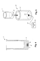
- the RFID component 10 as used in the present invention will be explained in detail.
- the RFID component 10 comprises a metal housing 11 and an RFID tag 12 provided within the metal housing 11.
- the metal housing hereby preferably has a cylindrical shape with a diameter D between 3mm and 12mm, preferably of 10mm and a height H between 2mm and 7mm, preferably of 4,5mm.
- the present invention is not limited to a metal housing with a cylindrical shape but can also comprise a metal housing with a cubical shape or the like.
- the metal housing 11 has an opening 14 on one of its plane sides and the metal can be filled with a resin 13 embedding the RFID tag 12.
- a resin 13 embedding the RFID tag 12.
- the resin 13 can also be omitted or another component instead of resin 13 can be used.
- the metal container is made of stainless steel or any other material suitable for shielding microwave radiation and the walls have a maximum thickness of 2 mm.
- the electromagnetic waves of the RFID communication can pass through the wall of the metal housing 11.
- the RFID tag is shielded from the electromagnetic radiation of the microwave oven, which usually lies in a much higher range, for example in the range of 2450 MHz.
- the diameter D of the metal housing 11 of about 10mm is provides an additional inventive merit of the present invention, since a diameter significantly deviating therefrom would not shield the microwave radiation but rather attenuate it so that the RFID tag 12 within the metal housing 11 would be destroyed.
- the RFID component 10 as used in the present invention thus provides the possibility of providing an RFID tag 12 in order to wirelessly communicate with a corresponding RFID reader/writer, but on the other hand provides an RFID component 10 which shields the RFID tag 12 from microwave radiation.
- the radio frequency identification, RFID, system as used in the present invention corresponds to common RFID systems, which are widespread and known in the art. A detailed description will therefore not be provided.
- the RFID technology allows contactless transmission of data between the transponder, i.e. the RFID tag 12, and the reading and/or writing unit and vice versa.
- the RFID tag 12 can be an active transponder having an integrated power supply or a passive transponder without an own power supply, which is powered to transmit, receive and/or store data by the electromagnetic field from the RFID reading and/or writing unit.
- common RFID systems may use any frequency between 30kHz and 3 GHz
- the present invention is concerned with RFID systems operating on a frequency range equal to or below 134kHz, e.g. at 125kHz.
- Fig. 3a shows a cross section of a vessel 1 as used in the present invention and fig. 3b shows a top view of such a vessel 1.
- the vessel 1 preferably has a cylindrical shape, but can also have any other cross-section, such as rectangular, elliptical or the like.
- the vessel 1 as used in the present invention comprises a side wall 3 and a bottom 2.
- the vessel 1 as used in the present invention at its underside 4 of the bottom 2 comprises a recess 6 which is adapted to receive the previously described RFID component 10 therein.
- the recess thus has substantially the same shape as the RFID component 10, so that the RFID component 10 when inserted into the recess 6 flushes with the inner walls of the recess 6.
- the term "underside” is intended to refer to the side of the bottom 2 being on the outside of the vessel 1.
- the terms “upper” and “lower” when used in the present specification are intended to refer the position of components when the vessel 1 standing in upright position, i.e. in the position in which it is normally used during the processing steps.
- the height H2 of the recess 6 corresponds to or is larger than the height H of the RFID component 10. In a preferred embodiment the height H2 corresponds to 6 mm.
- the diameter D1 of the recess 6 corresponds to or is larger than the diameter D of the RFID component 10 in order to receive the RFID component 10 therein. In a preferred embodiment the diameter D1 of the recess equals 10mm.
- the height H 1 of the bottom 2 with respect to the prior art vessel is increased, so that the complete height H1 of the bottom 2 reaching from the underside 4 of the bottom 2 to the inner basement 5 corresponds to at least 20 mm.
- the vessel 1 according to the present invention with this arrangement is able to sustain temperatures up to 300° without any damage to the RFID component 10.
- the shape of the recess 6 can entirely correspond to the outer shape of the RFID component 10, so that the RFID component 10 at all sides flushes with the walls of the recess 6.
- an additional air cavity 7 is provided between the RFID component 10 when inserted into the recess 6 and the bottom 2 below the recess.
- This air cavity 7 provides an additional isolation from high temperatures developed within the vessel 1.
- the air cavity 7 it is thus also possible to use a vessel 1 with a reduced height H1 of the bottom, since the air cavity additionally shields the RFID component 10 from heat within the vessel 1.
- the air cavity 7 thus can provide an additional temperature shield and/or allows to reduce the material needed for the vessel 1.
- the air cavity 7 likewise has a cylindrical shape.
- the diameter D2 of the air cavity 7 is smaller than the diameter D1 of the recess 6, in order to avoid that the RFID component 10 when inserted into the recess 6 slides into the air cavity 7.
- the diameter D2 preferably corresponds to 9 mm.
- the height H3 of the air cavity corresponds to 1,5 mm.
- any other shape of the air cavity 7 is possible, e.g. a cubical shape, a spherical or hemispherical shape, a pyramidal shape or the like.
- Fig. 3b shows a top view on a vessel 1 as used in the present invention and shows that the recess 6 preferably is provided in the center of the bottom 2, so that the recess 6 in case of a cylindrical vessel 1 is concentrical to the outer shape of the vessel 1.
- any other positioning of the recess at the bottom 2 is possible.
- the vessel 1 is made of a material being microwave transparent, heat resistant and acid resistant, such a polymers like polypropylene (PP), polyethylene (PE), polytetrafluoroethylene (PTFE, also known under Teflon®), perfluoroalkoxy (PFA) or any combination derivates thereof.
- PP polypropylene
- PE polyethylene
- PTFE polytetrafluoroethylene
- PFA perfluoroalkoxy
- Fig. 4 shows the assembled vessel 1 according to the present invention including the RFID component 10.
- the RFID component 10 is inserted into the recess 6. Shown in fig. 4 is the embodiment where an additional air cavity 7 is provided. However, as previously explained, the air cavity 7 can also be omitted.
- the recess 6 is sealed with a corrosion protection layer 8, which protects the inserted RFID component 10 from corrosion caused either by high temperatures and/or acid vapors.
- the corrosion protection layer can comprise polyether ether ketone, polytetrafluoroethylene, other suitable materials adapted to enable a corrosion protection or any combination thereof.
- the height H2 of the recess 6 preferably is slightly larger than the height H of the RFID component 10, so that some additional space for the corrosion protection layer 8 is left within the recess 6.
- the corrosion protection layer 8 can also be used to fill any cavities within the recess 6 except the air cavity 7 and to fix the RFID component 10 within the recess 6.
- the vessel 1 with the RFID tag 12 allows using all the advantages and features of an RFID tag 12 including a simple and automatic writing and/or reading of sample related parameters. Further, with the vessel 1 according to the present invention it is ensured that the vessel 1 with the RFID tag 12 will not be destroyed or damaged by any of the subsequent processing steps during the chemical analysis. More specifically, due to the metal housing of the RFID component 10 having a specific diameter D, the RFID tag 12 is shielded from microwave radiation. On the other hand, since as communication frequency for the RFID tag 12 a comparatively low frequency is used, the communication waves of the RFID communication can pass through the metal housing 11 without being interrupted.
- the RFID component 10 is shielded from high temperatures created by the sample within the vessel 1. For example, when a processing step including insertion into a microwave oven is provided, then temperatures up to 300° C can be reached. With an air cavity 7 is provided, an additional temperature shielding is achieved.
- any RFID reader/writer suitable for the specification of the RFID tag 12 commonly known can be used.
- a reading/writing unit is used allowing a simple insertion of the vessel and a secure reading of the RFID tag 12. Such a unit is shown in fig. 5 .
- the RFID reading/writing unit 20 comprises a container 21 having a shape corresponding to the shape of the vessel 1.
- the vessel 1 thereby can be inserted into the container 21, so that the position of the vessel 1 within the container 21 is fixed.
- An antenna 22 for reading from the RFID tag 12 and/or writing onto the RFID tag 12 is positioned at the bottom of the container 21, so that when the vessel 1 is inserted into the container 21, the RFID tag 12 is in the vicinity of the antenna 22.
- Via a corresponding transmission line 23 the signals from the antenna 22 are transmitted to or received from a corresponding processing unit 24.
- the antenna 22, the transmission line 23 and the processing unit 24 are located in a single block or component.
- the present invention is not limited to such a reading/writing unit, but any other commonly known RFID unit adapted to carry out reading and/or writing processes for this RFID tag 12 can be used.
- sample-related parameters at the beginning of the analysis process can be written onto the RFID tag 12.
- a reading unit either at each processing station or a common reading unit for some or all processing stations is provided, which reads the sample-related parameters and submits the sample-related parameters to the respective processing station, which in turn adapts the processing step accordingly.
- the vessel 1 according to the present invention can be used within any type of system making use of RFID communication, however a preferred system 30 will be described with reference to fig. 6 .
- a writing unit 31 which preferably is a combined reading and writing unit 31 is provided.
- the reading and writing unit 31 is connected to a central computer 32, which can be operated in the usual manner by a user.
- a balance 33 for weighing the sample when loaded into the vessel 1 is also provided, which is optionally also connected to the central computer 32.
- the user weighs the sample to be analyzed using the balance 33 and preferably the balance 33 transmits the weight to the computer 32.
- the user can also manually input the weight into the central computer 32.
- the user at the computer 32 enters additional sample-related data such as for example sample type, name, batch ID, reagents, quantities thereof, or the like, so that the computer 32 is adapted to collect all data related to the sample including the weight.
- the RFID tag 12 is then brought in vicinity of the reading and writing unit 31.
- the information stored in the computer 32 is then submitted to the reading and writing unit 31 and stored on the RFID tag 12. Additionally, all data are also kept stored within the computer 32.
- the unit 31 can also be a pure writing unit without reading functionality.
- the vessel 1 with the RFID tag 12 now due to information written onto the RFID tag 12 comprises all information necessary for uniquely identifying the sample therein and further for deciding on the following processing steps.
- At least one processing station is provided for carrying out a predetermined processing step on the sample within the vessel 1.
- Each processing station is connected to a RFID reading unit, which can read the sample-related data from the RFID tag 12 and submit them to the processing station, which in turn adapts the processing step to the sample, i.e. to the weight, type or the like of the sample.
- a dosing station 34 can be provided, which is connected to a first reading unit 35.
- the vessel 1 is put onto the first reading unit 35, which reads the data from the RFID tag 12 and submits the data to the dosing station 34.
- the dozing station 34 will select type and amount of reagents to be added to the sample.
- the first reading unit 35 can also be directly integrated into the dosing station.
- the dosing station 34 can be connected with the computer 32, and submit all the information regarding the processing steps to the computer 32. This has the advantage, that the within the computer 32 all processing steps carried out on the sample can be centrally stored and accessed at any time. However, such a connection is not necessarily present.
- a further example of a processing station is an oven 36, for example a microwave labstation which is likewise connected to a second reading unit 37, which alternatively can also be integrated into the oven 36.
- the second reading unit 37 again reads from the RFID tag 12 sample related parameters and transmits them to the oven 36, which in turn adapts the processing steps accordingly, i.e. the applied radiation power, radiation duration or the like.
- the oven 36 is also connected to the computer 32 and adapted to submit the information regarding the accomplished processing steps to the computer 32.
- the reading units 35, 37 associated with the processing stations are combined reading and writing units, so that the processing steps performed by the respective processing stations 34, 36 can be also written on the RFID tag 12.
- the reading and writing unit 31 or any other reading unit the data on the RFID tag 12 can be read in order to obtain all sample-related data and all processing steps stored thereon.
- a central server 38 or a database can be provided for storing all sample-related data for all samples which have been analyzed. This includes weight and type of sample, a batch ID, amount and type of added reagents, duration and temperature curves of the oven and the like. This makes it easy for a person to recall at any time the complete processing steps for each sample.
- a vessel 1 according to the present invention Such an easy collection of data and an automatic recognition of the processing steps to be carried out become only possible with a vessel 1 according to the present invention. Only with the vessel 1 according to the present invention a microwave resistant, heat resistant, pressure resistant and corrosion resistant vessel 1 can be provided, which at the same time does not hinder the propagation of the waves for RFID communication.
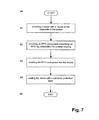
- step S0 The process starts in step S0.
- step S1 a vessel 1 is provided having a recess 6 at the underside 4 of the bottom 2, wherein said recess 6 and the bottom 2 have the above-described properties.
- step S2 a RFID component 10 comprising a RFID tag 12 embedded into a metal housing 11 is provided having the above-described properties.
- step S3 the RFID component 10 is inserted into the recess 6 and in the next step S4 the recess 6 is sealed with a corrosion protection layer 8.
- an improved vessel 1 for chemical analysis processes is provided, which allows to simplify the process and to automate process steps, which is results is less errors and a simplified processing. Further, with the present invention data for each sample can be collected and permanently stored in order to be recalled at any time. This allows to easily keeping an overview over all samples all the corresponding processing steps.
Landscapes
- Engineering & Computer Science (AREA)
- Computer Hardware Design (AREA)
- Microelectronics & Electronic Packaging (AREA)
- Physics & Mathematics (AREA)
- General Physics & Mathematics (AREA)
- Theoretical Computer Science (AREA)
- Chemical & Material Sciences (AREA)
- Analytical Chemistry (AREA)
- Health & Medical Sciences (AREA)
- Clinical Laboratory Science (AREA)
- Chemical Kinetics & Catalysis (AREA)
- Automatic Analysis And Handling Materials Therefor (AREA)
Abstract
a corrosion protection layer (8) sealing said recess (6). The present invention further relates to a system (30) for performing chemical analysis and using the data stored on the radio frequency identification tag (12) for adapting the processing steps.
Description
- The present invention relates to a vessel with an RFID tag, to a system for performing sample analysis using said vessel and to a method of manufacturing such a vessel. In particular, the present invention is concerned with a vessel comprising an RFID tag being resistant to the strains of a chemical analysis process for example at high temperatures (up to 300°C) and pressure (up to 60 bar) in a microwave field.
- In the field of chemical analysis and treatment of samples, vessels are used into which the samples are filled to undergo the corresponding treatments. Hereby, it is important to uniquely identify each sample within the vessel.
- Depending on the processing steps, the microwave transparent vessel and the sample undergo different processes, such as for example addition of chemical reagents, including also aggressive reagents such as acid or the like, heating or submission to microwave radiation. Due to the different chemical processes in which the vessels containing the samples are involved, the possibilities of adding information to the vessels identifying the sample contained within the vessel are very limited. Electric components, transponders or the like are not resistant to the different processes the vessel has to undergo. On the other hand, a tape attached to the vessel indicating the sample might get lost during the analysis process. Writing on the vessel itself is not feasible as the vessel is made of PTFE compounds on which ink or graphite do not stick.
- The prior art vessels are therefore limited in terms of ease of use and reliability.
- In view of the above, there is thus a need to provide an improved vessel which overcomes at least some limitation of the known processes.
- It is therefore the need to provide a vessel allowing an easy, simple and secure identification of samples within the vessel. It is further a need to provide such a vessel with can resist the strains of the chemical analysis process.
- Accordingly, this object is achieved by means of the features of the independent claims. The dependent claims develop further the central idea of the invention. According to a first aspect the present invention relates to a vessel, comprising
a recess at the underside of said vessel, a radio frequency identification component provided within said recess, wherein the radio frequency identification component comprises a radio frequency identification tag embedded into a metal housing,
and a corrosion protection layer sealing said recess. - According to a second aspect the present invention relates to a system for performing sample analysis, comprising a vessel according to any of the preceding claims adapted to receive a sample therein, a writing unit for writing onto the radio frequency identification component sample related parameters, at least one processing station for performing a predefined processing step to the sample within the vessel, and at least one radio frequency identification reading unit connected to said at least one processing station for reading the sample related parameters from the radio frequency identification tag and submitting said parameters to the at least one processing station,
wherein the processing station adapts the processing step based on the submitted sample related parameters. According to a further aspect, the present invention relates to a method of manufacturing a vessel, comprising the steps of providing a vessel with recess at the underside of the bottom, providing a radio frequency identification component comprising a radio frequency identification tag embedded into a metal housing,
inserting the radio frequency identification component into the recess, and
sealing the recess with a corrosion protection layer. - The present invention is further described hereinafter with reference to some of its embodiments shown in the accompanying drawings in which:
-
fig. 1 depicts a vessel according to the prior art, -
fig. 2 schematically depicts an RFID component used in the present invention, -
fig. 3a depicts a vertical cross section of a vessel as used in the present invention, -
fig. 3b depicts a top view on a vessel as used in the present invention, -
fig. 4 depicts a vertical cross section of a vessel with an RFID component according to the present invention,fig. 5 schematically depicts an RFID writing/reading unit according to the present invention, -
fig. 6 shows a system for performing sample analysis according to the present invention, and -
fig. 7 . shows the process steps of the method for manufacturing a vessel according to the present invention. -
Fig. 1 shows avessel 101 as known in prior art. The term "vessel" as used in the present specification refers to any type of container adapted to receive a probe or sample therein and to undergo different processing and analysis steps. The vessel is preferably made of a polymer based material (PTFE or others) transparent to microwaves. -
Fig. 1 shows a cross section of avessel 101 according to prior art. Thevessel 101 has a cylindrical shape withside walls 103 and abottom 102. The thickness T of thebottom 102, i. e. extension of thebottom 102 between theunderside 104 of thebottom 102 andinner basement 105 according to prior art usually lies within a range of 10 mm. - The
vessel 101 according to prior art in order to identify the sample contained therein is usually labeled with a pen or a corresponding tape adhered onto theside wall 103. - However, as already described, this method of marking the sample has a high risk of failure, is uncomfortable and the inscription on the vessel or the tape may be lost, so that a unique identification of the sample contained therein becomes impossible.
- The present invention therefore proposes to use a specific vessel comprising a radio frequency identification (RFID) tag. The inventive merit of the present invention lies within the finding how to implement such an RFID tag into a vessel, so that the vessel with the integrated RFID tag will be resistant to all the processing steps of the chemical analysis including and the irradiation of the microwave field.
- For this purpose according to the present invention a specifically configured RFID component is used and additionally the vessel is modified in a specific way. Referring to
fig. 2 theRFID component 10 as used in the present invention will be explained in detail. - The
RFID component 10 comprises ametal housing 11 and anRFID tag 12 provided within themetal housing 11. The metal housing hereby preferably has a cylindrical shape with a diameter D between 3mm and 12mm, preferably of 10mm and a height H between 2mm and 7mm, preferably of 4,5mm. However, the present invention is not limited to a metal housing with a cylindrical shape but can also comprise a metal housing with a cubical shape or the like. - The
metal housing 11 has anopening 14 on one of its plane sides and the metal can be filled with aresin 13 embedding theRFID tag 12. However, it is also possible to provide ametal housing 11, which is closed on all sides. Further, theresin 13 can also be omitted or another component instead ofresin 13 can be used. - The metal container is made of stainless steel or any other material suitable for shielding microwave radiation and the walls have a maximum thickness of 2 mm.
- With this configuration when using a frequency for the RFID communication which is comparatively low, i. e. below 134 kHz, the electromagnetic waves of the RFID communication can pass through the wall of the
metal housing 11. On the other hand, due to themetal housing 11 and the specific size of the metal housing the RFID tag is shielded from the electromagnetic radiation of the microwave oven, which usually lies in a much higher range, for example in the range of 2450 MHz. - The diameter D of the
metal housing 11 of about 10mm is provides an additional inventive merit of the present invention, since a diameter significantly deviating therefrom would not shield the microwave radiation but rather attenuate it so that theRFID tag 12 within themetal housing 11 would be destroyed. - The
RFID component 10 as used in the present invention thus provides the possibility of providing anRFID tag 12 in order to wirelessly communicate with a corresponding RFID reader/writer, but on the other hand provides anRFID component 10 which shields theRFID tag 12 from microwave radiation. - The radio frequency identification, RFID, system as used in the present invention corresponds to common RFID systems, which are widespread and known in the art. A detailed description will therefore not be provided. Generally, the RFID technology allows contactless transmission of data between the transponder, i.e. the
RFID tag 12, and the reading and/or writing unit and vice versa. TheRFID tag 12 can be an active transponder having an integrated power supply or a passive transponder without an own power supply, which is powered to transmit, receive and/or store data by the electromagnetic field from the RFID reading and/or writing unit. Even though common RFID systems may use any frequency between 30kHz and 3 GHz, the present invention is concerned with RFID systems operating on a frequency range equal to or below 134kHz, e.g. at 125kHz. - With reference to
figs. 3a and 3b now thevessel 1 as used within the present invention will be explained. -
Fig. 3a shows a cross section of avessel 1 as used in the present invention andfig. 3b shows a top view of such avessel 1. - The
vessel 1 preferably has a cylindrical shape, but can also have any other cross-section, such as rectangular, elliptical or the like. - Like the vessel of the prior art, the
vessel 1 as used in the present invention comprises aside wall 3 and abottom 2. Thevessel 1 as used in the present invention at itsunderside 4 of thebottom 2 comprises arecess 6 which is adapted to receive the previously describedRFID component 10 therein. The recess thus has substantially the same shape as theRFID component 10, so that theRFID component 10 when inserted into therecess 6 flushes with the inner walls of therecess 6. The term "underside" is intended to refer to the side of the bottom 2 being on the outside of thevessel 1. Generally, the terms "upper" and "lower" when used in the present specification are intended to refer the position of components when thevessel 1 standing in upright position, i.e. in the position in which it is normally used during the processing steps. - Preferably, the height H2 of the
recess 6 corresponds to or is larger than the height H of theRFID component 10. In a preferred embodiment the height H2 corresponds to 6 mm. Likewise, the diameter D1 of therecess 6 corresponds to or is larger than the diameter D of theRFID component 10 in order to receive theRFID component 10 therein. In a preferred embodiment the diameter D1 of the recess equals 10mm. - For shielding the
RFID component 10 when inserted into therecess 6 from high temperatures of the sample within thevessel 1, theheight H 1 of the bottom 2 with respect to the prior art vessel is increased, so that the complete height H1 of the bottom 2 reaching from theunderside 4 of the bottom 2 to theinner basement 5 corresponds to at least 20 mm. Thereby, theRFID component 10 due to the amount of bottom material between theRFID component 10 and any heated sample within thevessel 1 is protected from damage due to heat. Thevessel 1 according to the present invention with this arrangement is able to sustain temperatures up to 300° without any damage to theRFID component 10. - According to one embodiment the shape of the
recess 6 can entirely correspond to the outer shape of theRFID component 10, so that theRFID component 10 at all sides flushes with the walls of therecess 6. - However, in a preferred embodiment, an
additional air cavity 7 is provided between theRFID component 10 when inserted into therecess 6 and thebottom 2 below the recess. Thisair cavity 7 provides an additional isolation from high temperatures developed within thevessel 1. When providing such anair cavity 7 it is thus also possible to use avessel 1 with a reduced height H1 of the bottom, since the air cavity additionally shields theRFID component 10 from heat within thevessel 1. Theair cavity 7 thus can provide an additional temperature shield and/or allows to reduce the material needed for thevessel 1. - In a preferred embodiment the
air cavity 7 likewise has a cylindrical shape. Preferably, the diameter D2 of theair cavity 7 is smaller than the diameter D1 of therecess 6, in order to avoid that theRFID component 10 when inserted into therecess 6 slides into theair cavity 7. The diameter D2 preferably corresponds to 9 mm. The height H3 of the air cavity corresponds to 1,5 mm. However, any other shape of theair cavity 7 is possible, e.g. a cubical shape, a spherical or hemispherical shape, a pyramidal shape or the like. -
Fig. 3b shows a top view on avessel 1 as used in the present invention and shows that therecess 6 preferably is provided in the center of thebottom 2, so that therecess 6 in case of acylindrical vessel 1 is concentrical to the outer shape of thevessel 1. However, any other positioning of the recess at thebottom 2 is possible. - The
vessel 1 is made of a material being microwave transparent, heat resistant and acid resistant, such a polymers like polypropylene (PP), polyethylene (PE), polytetrafluoroethylene (PTFE, also known under Teflon®), perfluoroalkoxy (PFA) or any combination derivates thereof. -
Fig. 4 shows the assembledvessel 1 according to the present invention including theRFID component 10. - The
RFID component 10 is inserted into therecess 6. Shown infig. 4 is the embodiment where anadditional air cavity 7 is provided. However, as previously explained, theair cavity 7 can also be omitted. - The
recess 6 is sealed with a corrosion protection layer 8, which protects the insertedRFID component 10 from corrosion caused either by high temperatures and/or acid vapors. The corrosion protection layer can comprise polyether ether ketone, polytetrafluoroethylene, other suitable materials adapted to enable a corrosion protection or any combination thereof. - In order to achieve a
plain underside 4 of thebottom 2 of thevessel 1, the height H2 of therecess 6 preferably is slightly larger than the height H of theRFID component 10, so that some additional space for the corrosion protection layer 8 is left within therecess 6. When inserting the corrosion protection layer 8 into therecess 6, the corrosion protection layer will flush with theunderside 4 of thebottom 2. - In case that the
recess 6 is larger than theRFID component 10 and/or has a different shape, the corrosion protection layer 8 can also be used to fill any cavities within therecess 6 except theair cavity 7 and to fix theRFID component 10 within therecess 6. - The
vessel 1 with theRFID tag 12 according to the present invention allows using all the advantages and features of anRFID tag 12 including a simple and automatic writing and/or reading of sample related parameters. Further, with thevessel 1 according to the present invention it is ensured that thevessel 1 with theRFID tag 12 will not be destroyed or damaged by any of the subsequent processing steps during the chemical analysis. More specifically, due to the metal housing of theRFID component 10 having a specific diameter D, theRFID tag 12 is shielded from microwave radiation. On the other hand, since as communication frequency for the RFID tag 12 a comparatively low frequency is used, the communication waves of the RFID communication can pass through themetal housing 11 without being interrupted. Further, by providing abottom 2 of thevessel 1 with an increased thickness compared to prior art vessels, theRFID component 10 is shielded from high temperatures created by the sample within thevessel 1. For example, when a processing step including insertion into a microwave oven is provided, then temperatures up to 300° C can be reached. With anair cavity 7 is provided, an additional temperature shielding is achieved. - In case that a processing step provides the use of acid which is heated, acid vapors may cause damage to the
RFID component 10. This is prevented by providing a corrosion protection layer 8 shielding theRFID component 10 from corrosion caused due to temperature and/or acid. On the other hand, the corrosion protection layer 8 does not hinder the propagation of the RFID frequency waves. - For reading from the
RFID tag 12 or writing onto theRFID tag 12 any RFID reader/writer suitable for the specification of theRFID tag 12 commonly known can be used. However, according to a preferred embodiment of the present invention, a reading/writing unit is used allowing a simple insertion of the vessel and a secure reading of theRFID tag 12. Such a unit is shown infig. 5 . - Preferably, the RFID reading/
writing unit 20 comprises acontainer 21 having a shape corresponding to the shape of thevessel 1. Thevessel 1 thereby can be inserted into thecontainer 21, so that the position of thevessel 1 within thecontainer 21 is fixed. Anantenna 22 for reading from theRFID tag 12 and/or writing onto theRFID tag 12 is positioned at the bottom of thecontainer 21, so that when thevessel 1 is inserted into thecontainer 21, theRFID tag 12 is in the vicinity of theantenna 22. Via acorresponding transmission line 23 the signals from theantenna 22 are transmitted to or received from a correspondingprocessing unit 24. In a preferred embodiment of this invention theantenna 22, thetransmission line 23 and theprocessing unit 24 are located in a single block or component. - However, the present invention is not limited to such a reading/writing unit, but any other commonly known RFID unit adapted to carry out reading and/or writing processes for this
RFID tag 12 can be used. - With reference to
fig. 6 now asystem 30 for performing sample analysis according to the present invention and using thevessel 1 with theRFID tag 12 according to the present invention will be explained in more detail. The present system makes use of the possibilities of an RFID system. - Basically, according to the present invention, sample-related parameters at the beginning of the analysis process can be written onto the
RFID tag 12. When thevessel 1 is then moved on to several processing stations for performing a predefined processing step to the sample within thevessel 1, a reading unit either at each processing station or a common reading unit for some or all processing stations is provided, which reads the sample-related parameters and submits the sample-related parameters to the respective processing station, which in turn adapts the processing step accordingly. - The
vessel 1 according to the present invention can be used within any type of system making use of RFID communication, however apreferred system 30 will be described with reference tofig. 6 . - A
writing unit 31 which preferably is a combined reading and writingunit 31 is provided. The reading and writingunit 31 is connected to acentral computer 32, which can be operated in the usual manner by a user. Abalance 33 for weighing the sample when loaded into thevessel 1 is also provided, which is optionally also connected to thecentral computer 32. - To make it more clear, at the beginning the user weighs the sample to be analyzed using the
balance 33 and preferably thebalance 33 transmits the weight to thecomputer 32. Alternatively, if no connection between thebalance 33 and thecentral computer 32 is present, the user can also manually input the weight into thecentral computer 32. The user at thecomputer 32 enters additional sample-related data such as for example sample type, name, batch ID, reagents, quantities thereof, or the like, so that thecomputer 32 is adapted to collect all data related to the sample including the weight. TheRFID tag 12 is then brought in vicinity of the reading and writingunit 31. The information stored in thecomputer 32 is then submitted to the reading and writingunit 31 and stored on theRFID tag 12. Additionally, all data are also kept stored within thecomputer 32. It is to be noted, that theunit 31 can also be a pure writing unit without reading functionality. - The
vessel 1 with theRFID tag 12 now due to information written onto theRFID tag 12 comprises all information necessary for uniquely identifying the sample therein and further for deciding on the following processing steps. - According to the
system 30 of the present invention, at least one processing station is provided for carrying out a predetermined processing step on the sample within thevessel 1. Each processing station is connected to a RFID reading unit, which can read the sample-related data from theRFID tag 12 and submit them to the processing station, which in turn adapts the processing step to the sample, i.e. to the weight, type or the like of the sample. - For example, as a first processing station a
dosing station 34 can be provided, which is connected to afirst reading unit 35. Thevessel 1 is put onto thefirst reading unit 35, which reads the data from theRFID tag 12 and submits the data to thedosing station 34. On basis of the data, e.g. the type of sample, weight of sample or the like, the dozingstation 34 will select type and amount of reagents to be added to the sample. Thefirst reading unit 35 can also be directly integrated into the dosing station. - In a possible implementation, the
dosing station 34 can be connected with thecomputer 32, and submit all the information regarding the processing steps to thecomputer 32. This has the advantage, that the within thecomputer 32 all processing steps carried out on the sample can be centrally stored and accessed at any time. However, such a connection is not necessarily present. - A further example of a processing station is an
oven 36, for example a microwave labstation which is likewise connected to asecond reading unit 37, which alternatively can also be integrated into theoven 36. Thesecond reading unit 37 again reads from theRFID tag 12 sample related parameters and transmits them to theoven 36, which in turn adapts the processing steps accordingly, i.e. the applied radiation power, radiation duration or the like. Optionally, theoven 36 is also connected to thecomputer 32 and adapted to submit the information regarding the accomplished processing steps to thecomputer 32. - In a further alternative embodiment, the reading
units respective processing stations RFID tag 12. Using the reading and writingunit 31 or any other reading unit, the data on theRFID tag 12 can be read in order to obtain all sample-related data and all processing steps stored thereon. - In a further embodiment a
central server 38 or a database can be provided for storing all sample-related data for all samples which have been analyzed. This includes weight and type of sample, a batch ID, amount and type of added reagents, duration and temperature curves of the oven and the like. This makes it easy for a person to recall at any time the complete processing steps for each sample. - Such an easy collection of data and an automatic recognition of the processing steps to be carried out become only possible with a
vessel 1 according to the present invention. Only with thevessel 1 according to the present invention a microwave resistant, heat resistant, pressure resistant and corrosionresistant vessel 1 can be provided, which at the same time does not hinder the propagation of the waves for RFID communication. - With respect to
fig. 7 now the method of manufacturing such avessel 1 according to the present invention will be explained. - The process starts in step S0.
- In step S1 a
vessel 1 is provided having arecess 6 at theunderside 4 of thebottom 2, wherein saidrecess 6 and the bottom 2 have the above-described properties. In the next S2 aRFID component 10 comprising aRFID tag 12 embedded into ametal housing 11 is provided having the above-described properties. - In step S3 the
RFID component 10 is inserted into therecess 6 and in the next step S4 therecess 6 is sealed with a corrosion protection layer 8. - The process ends in step S5.
- With the present invention thus an
improved vessel 1 for chemical analysis processes is provided, which allows to simplify the process and to automate process steps, which is results is less errors and a simplified processing. Further, with the present invention data for each sample can be collected and permanently stored in order to be recalled at any time. This allows to easily keeping an overview over all samples all the corresponding processing steps.
Claims (15)
- Vessel (1), comprising
a recess (6) at the underside of said vessel (1),
a radio frequency identification component (10) provided within said recess (6), wherein the radio frequency identification component (10) comprises a radio frequency identification tag (12) embedded into a metal housing (11),
and
a corrosion protection layer (8) sealing said recess (6). - Vessel (1) according to claim 1,
wherein the metal housing (11) has a cylindrical shape, wherein the diameter (D) of the metal housing (11) lies within the range of 3mm to 12mm, preferably equals 10mm
and
the height (H) of the metal housing (11) lies within the range of 2mm to 7mm, preferably equals 4,5mm. - Vessel (1) according to claim 1 or 2,
wherein said metal housing (11) is made of stainless steel having a maximal thickness of 2mm and/or
wherein said metal housing (11) is open on at least one side or closed on all sides. - Vessel (1) according to any of the preceding claims,
wherein said radio frequency identification component (10) further comprises a resin (13) filled into said metal housing (11) and embedding said radio frequency identification tag (12). - Vessel (1) according to any of the preceding claims,
wherein the communication frequency of said RFID tag (12) equals or is less than 134 kHZ. - Vessel (1) according to any of the preceding claims,
wherein said recess (6) has a cylindrical shape,
wherein the diameter (D1) of the recess (6) equals the lateral dimension of the metal housing (11), and
wherein the height (H2) of the recess (6) is larger than the height (H) of the metal housing (11), preferably equals 6mm. - Vessel (1) according to any of the preceding claims,
wherein said corrosion protection layer (8) comprises polyether ether ketone, polytetrafluoroethylene or any combination thereof and/or
wherein said vessel (1) is made of polymers like polypropylene, polyethylene, polytetrafluoroethylene, perfluoroalkoxy or any combinations thereof. - Vessel (1) according to any of the preceding claims,
wherein the bottom (2) of the vessel (1) has a thickness of at least 20mm for shielding the radio frequency identification component (10) from heat emitted by a sample within the vessel (1). - Vessel (1) according to any of the preceding claims,
wherein an air cavity (7) is provided between the radio frequency identification component (10) and the upper bottom part surrounding the radio frequency identification component (10). - System for performing sample analysis, comprising
a vessel (1) according to any of the preceding claims adapted to receive a sample therein,
a writing unit (31) for writing onto the radio frequency identification component (10) sample related parameters, at least one processing station (34, 36) for performing a predefined processing step to the sample within the vessel (1), and
at least one radio frequency identification reading unit (35, 37) connected to said at least one processing station (34, 36) for reading the sample related parameters from the radio frequency identification tag (12) and submitting said parameters to the at least one processing station (34, 36),
wherein said processing station (34, 36) adapts the processing step based on the stored sample related parameters. - System according to claim 10,
wherein said processing station is a dosing station (34) for adding reagents to the sample, and
wherein the dosing station (34) automatically selects number, type and amount of reagents to be added based on the stored sample-related parameters. - System according to claim 10 or 11,
wherein said processing station is a microwave labstation (36) for heating the sample, and
wherein microwave labstation (36) automatically selects the power and duration of microwave radiation based on the stored sample-related parameters. - System according to any of claims 10 to 12,
wherein said at least one radio frequency identification reading unit (35, 37) is a combined radio frequency identification reading/writing unit and adapted to write onto the radio frequency identification tag (12) processing data representing the executed process steps. - System according to any of claims 10 to 13,
further comprising a database (38) for storing the sample-related data and executed processing steps for each sample. - Method of manufacturing a vessel (1),
comprising the steps of
providing (S1) a vessel (1) with recess (6) at the underside (4) of the bottom (2),
providing (S2) a radio frequency identification component (10) comprising a radio frequency identification tag (12) embedded into a metal housing (11),
inserting (S3) the radio frequency identification component (10) into the recess (6), and
sealing (S4) the recess (6) with a corrosion protection layer (8).
Priority Applications (2)
| Application Number | Priority Date | Filing Date | Title |
|---|---|---|---|
| EP10425137A EP2383682B1 (en) | 2010-04-27 | 2010-04-27 | Vessel with RFID tag |
| US13/081,815 US20110262305A1 (en) | 2010-04-27 | 2011-04-07 | Vessel with RFID Tag |
Applications Claiming Priority (1)
| Application Number | Priority Date | Filing Date | Title |
|---|---|---|---|
| EP10425137A EP2383682B1 (en) | 2010-04-27 | 2010-04-27 | Vessel with RFID tag |
Publications (2)
| Publication Number | Publication Date |
|---|---|
| EP2383682A1 true EP2383682A1 (en) | 2011-11-02 |
| EP2383682B1 EP2383682B1 (en) | 2012-10-17 |
Family
ID=42655621
Family Applications (1)
| Application Number | Title | Priority Date | Filing Date |
|---|---|---|---|
| EP10425137A Not-in-force EP2383682B1 (en) | 2010-04-27 | 2010-04-27 | Vessel with RFID tag |
Country Status (2)
| Country | Link |
|---|---|
| US (1) | US20110262305A1 (en) |
| EP (1) | EP2383682B1 (en) |
Cited By (5)
| Publication number | Priority date | Publication date | Assignee | Title |
|---|---|---|---|---|
| GB2545879A (en) * | 2015-10-16 | 2017-07-05 | Dmm Int Ltd | Identification of items |
| NL2017100A (en) * | 2016-03-24 | 2017-10-02 | Van Straten Medical B V | An RFID tag mounted or mountable on surgical or medical equipment or on a surgical or medical instrument |
| JP2022071477A (en) * | 2020-10-28 | 2022-05-16 | 信越ポリマー株式会社 | Tagged container, tag fixing method, tag fixing structure and packaging |
| EP4120133A1 (en) * | 2021-07-13 | 2023-01-18 | etifix GmbH | System comprising a smart label and a shielding element as well as a microwavable crockery |
| EP4306212A1 (en) * | 2022-07-14 | 2024-01-17 | Milestone S.r.l. | Container for collecting, transporting and storing a biological tissue sample |
Families Citing this family (6)
| Publication number | Priority date | Publication date | Assignee | Title |
|---|---|---|---|---|
| DE102011087588A1 (en) * | 2011-12-01 | 2013-06-06 | Endress + Hauser Conducta Gesellschaft für Mess- und Regeltechnik mbH + Co. KG | Field device for automation technology |
| US8607981B2 (en) * | 2012-04-05 | 2013-12-17 | Christopher W Wojno | Grocery transport reusable container |
| CN105453113A (en) * | 2013-08-15 | 2016-03-30 | 富士通株式会社 | Rfid tag and method for manufacturing same |
| DE102018004849A1 (en) * | 2017-09-29 | 2019-04-04 | J.H. Tönnjes Gmbh | Method and device for providing a license plate, preferably a motor vehicle license plate, with a data carrier |
| DE102021118103B3 (en) | 2021-07-13 | 2022-10-27 | Etifix Gmbh | MICROWAVE SAFE SMART LABEL |
| CN115610811A (en) * | 2022-10-20 | 2023-01-17 | 北京宏诚创新科技有限公司 | A biological sample storage tube and packaging method |
Citations (1)
| Publication number | Priority date | Publication date | Assignee | Title |
|---|---|---|---|---|
| US20090115616A1 (en) * | 2007-11-06 | 2009-05-07 | Merrick Systems Inc. | RFID Transponder Enclosure for Harsh Environments |
Family Cites Families (2)
| Publication number | Priority date | Publication date | Assignee | Title |
|---|---|---|---|---|
| JP2007183919A (en) * | 2005-12-05 | 2007-07-19 | Nec Corp | Rfid tag |
| US8097199B2 (en) * | 2006-02-07 | 2012-01-17 | Rexam Healthcare Packaging Inc. | Molded plastic container and preform having insert-molded insert |
-
2010
- 2010-04-27 EP EP10425137A patent/EP2383682B1/en not_active Not-in-force
-
2011
- 2011-04-07 US US13/081,815 patent/US20110262305A1/en not_active Abandoned
Patent Citations (1)
| Publication number | Priority date | Publication date | Assignee | Title |
|---|---|---|---|---|
| US20090115616A1 (en) * | 2007-11-06 | 2009-05-07 | Merrick Systems Inc. | RFID Transponder Enclosure for Harsh Environments |
Cited By (8)
| Publication number | Priority date | Publication date | Assignee | Title |
|---|---|---|---|---|
| GB2545879A (en) * | 2015-10-16 | 2017-07-05 | Dmm Int Ltd | Identification of items |
| GB2545879B (en) * | 2015-10-16 | 2018-04-18 | Dmm Int Ltd | Identification of items |
| NL2017100A (en) * | 2016-03-24 | 2017-10-02 | Van Straten Medical B V | An RFID tag mounted or mountable on surgical or medical equipment or on a surgical or medical instrument |
| NL2016488A (en) * | 2016-03-24 | 2017-10-02 | Van Straten Medical B V | An RFID tag mounted or mountable on surgical or medical equipment or on a surgical or medical instrument. |
| JP2022071477A (en) * | 2020-10-28 | 2022-05-16 | 信越ポリマー株式会社 | Tagged container, tag fixing method, tag fixing structure and packaging |
| JP2024138147A (en) * | 2020-10-28 | 2024-10-07 | 信越ポリマー株式会社 | Tagged container, tag fixing method and tag fixing structure |
| EP4120133A1 (en) * | 2021-07-13 | 2023-01-18 | etifix GmbH | System comprising a smart label and a shielding element as well as a microwavable crockery |
| EP4306212A1 (en) * | 2022-07-14 | 2024-01-17 | Milestone S.r.l. | Container for collecting, transporting and storing a biological tissue sample |
Also Published As
| Publication number | Publication date |
|---|---|
| US20110262305A1 (en) | 2011-10-27 |
| EP2383682B1 (en) | 2012-10-17 |
Similar Documents
| Publication | Publication Date | Title |
|---|---|---|
| EP2383682B1 (en) | Vessel with RFID tag | |
| AU2005259981B2 (en) | Method of pre-treatment and staining of and support device for a biological sample | |
| JP5538419B2 (en) | A system for tracking vessels by wireless identification in an automated laboratory analyzer. | |
| JP3890277B2 (en) | Specimen instruction information creation system | |
| EP1851740B1 (en) | Rf tag on test strips, test strip vials and boxes | |
| US7932826B2 (en) | System for tracking the location of components, assemblies, and subassemblies in an automated diagnostic analyzer | |
| US9547782B2 (en) | Identification of biological samples | |
| EP2080553A1 (en) | A method and system to localise and identify at least one of a plurarility of test tubes | |
| EP3258411A1 (en) | Container management apparatus and wireless tag | |
| EP2081128A1 (en) | A laboratory device, a laboratory rack assembly and a method to couple an RFID chip | |
| JP6594431B2 (en) | Ion concentration measuring device | |
| EP2232409A1 (en) | An associated set of radio frequency identification ( rfid ) tagged containers for specimens from a patient | |
| CN103167909A (en) | Devices with RFID tags and fluidic elements | |
| CN102639244B (en) | Fluid analytical systems | |
| EP3182310B1 (en) | Method for storing temporary data in a memory of an rfid tag associated with a consumable of a laboratory instrument and system comprising a laboratory instrument, a consumable and an rfid tag | |
| US9679169B2 (en) | Sample carrier identification | |
| US20240019345A1 (en) | Container for collecting, transporting and storing a biological tissue sample | |
| JP5795999B2 (en) | Automatic analyzer | |
| Teng et al. | A laboratory specimen management system with commercially viable RFID solution | |
| EP4446745A1 (en) | Sample preparation | |
| JP2004089503A (en) | Blood collection tube, blood collection tube and blood collection system | |
| EP4694791A1 (en) | Sample collection device and associated methods | |
| HK40116174A (en) | Sample preparation | |
| CN111950664A (en) | Laboratory information management method for gene detection and inspection |
Legal Events
| Date | Code | Title | Description |
|---|---|---|---|
| 17P | Request for examination filed |
Effective date: 20110304 |
|
| AK | Designated contracting states |
Kind code of ref document: A1 Designated state(s): AT BE BG CH CY CZ DE DK EE ES FI FR GB GR HR HU IE IS IT LI LT LU LV MC MK MT NL NO PL PT RO SE SI SK SM TR |
|
| AX | Request for extension of the european patent |
Extension state: AL BA ME RS |
|
| PUAI | Public reference made under article 153(3) epc to a published international application that has entered the european phase |
Free format text: ORIGINAL CODE: 0009012 |
|
| RIC1 | Information provided on ipc code assigned before grant |
Ipc: G06K 19/077 20060101AFI20120418BHEP |
|
| GRAP | Despatch of communication of intention to grant a patent |
Free format text: ORIGINAL CODE: EPIDOSNIGR1 |
|
| GRAS | Grant fee paid |
Free format text: ORIGINAL CODE: EPIDOSNIGR3 |
|
| GRAA | (expected) grant |
Free format text: ORIGINAL CODE: 0009210 |
|
| AK | Designated contracting states |
Kind code of ref document: B1 Designated state(s): AT BE BG CH CY CZ DE DK EE ES FI FR GB GR HR HU IE IS IT LI LT LU LV MC MK MT NL NO PL PT RO SE SI SK SM TR |
|
| REG | Reference to a national code |
Ref country code: GB Ref legal event code: FG4D |
|
| REG | Reference to a national code |
Ref country code: CH Ref legal event code: NV Representative=s name: ISLER & PEDRAZZINI AG Ref country code: CH Ref legal event code: EP |
|
| REG | Reference to a national code |
Ref country code: IE Ref legal event code: FG4D |
|
| REG | Reference to a national code |
Ref country code: AT Ref legal event code: REF Ref document number: 580186 Country of ref document: AT Kind code of ref document: T Effective date: 20121115 |
|
| REG | Reference to a national code |
Ref country code: DE Ref legal event code: R096 Ref document number: 602010003244 Country of ref document: DE Effective date: 20121213 |
|
| REG | Reference to a national code |
Ref country code: NL Ref legal event code: VDEP Effective date: 20121017 |
|
| REG | Reference to a national code |
Ref country code: LT Ref legal event code: MG4D |
|
| PG25 | Lapsed in a contracting state [announced via postgrant information from national office to epo] |
Ref country code: IS Free format text: LAPSE BECAUSE OF FAILURE TO SUBMIT A TRANSLATION OF THE DESCRIPTION OR TO PAY THE FEE WITHIN THE PRESCRIBED TIME-LIMIT Effective date: 20130217 Ref country code: FI Free format text: LAPSE BECAUSE OF FAILURE TO SUBMIT A TRANSLATION OF THE DESCRIPTION OR TO PAY THE FEE WITHIN THE PRESCRIBED TIME-LIMIT Effective date: 20121017 Ref country code: SE Free format text: LAPSE BECAUSE OF FAILURE TO SUBMIT A TRANSLATION OF THE DESCRIPTION OR TO PAY THE FEE WITHIN THE PRESCRIBED TIME-LIMIT Effective date: 20121017 Ref country code: LT Free format text: LAPSE BECAUSE OF FAILURE TO SUBMIT A TRANSLATION OF THE DESCRIPTION OR TO PAY THE FEE WITHIN THE PRESCRIBED TIME-LIMIT Effective date: 20121017 Ref country code: NO Free format text: LAPSE BECAUSE OF FAILURE TO SUBMIT A TRANSLATION OF THE DESCRIPTION OR TO PAY THE FEE WITHIN THE PRESCRIBED TIME-LIMIT Effective date: 20130117 Ref country code: NL Free format text: LAPSE BECAUSE OF FAILURE TO SUBMIT A TRANSLATION OF THE DESCRIPTION OR TO PAY THE FEE WITHIN THE PRESCRIBED TIME-LIMIT Effective date: 20121017 Ref country code: HR Free format text: LAPSE BECAUSE OF FAILURE TO SUBMIT A TRANSLATION OF THE DESCRIPTION OR TO PAY THE FEE WITHIN THE PRESCRIBED TIME-LIMIT Effective date: 20121017 |
|
| PG25 | Lapsed in a contracting state [announced via postgrant information from national office to epo] |
Ref country code: GR Free format text: LAPSE BECAUSE OF FAILURE TO SUBMIT A TRANSLATION OF THE DESCRIPTION OR TO PAY THE FEE WITHIN THE PRESCRIBED TIME-LIMIT Effective date: 20130118 Ref country code: PT Free format text: LAPSE BECAUSE OF FAILURE TO SUBMIT A TRANSLATION OF THE DESCRIPTION OR TO PAY THE FEE WITHIN THE PRESCRIBED TIME-LIMIT Effective date: 20130218 Ref country code: LV Free format text: LAPSE BECAUSE OF FAILURE TO SUBMIT A TRANSLATION OF THE DESCRIPTION OR TO PAY THE FEE WITHIN THE PRESCRIBED TIME-LIMIT Effective date: 20121017 Ref country code: PL Free format text: LAPSE BECAUSE OF FAILURE TO SUBMIT A TRANSLATION OF THE DESCRIPTION OR TO PAY THE FEE WITHIN THE PRESCRIBED TIME-LIMIT Effective date: 20121017 Ref country code: SI Free format text: LAPSE BECAUSE OF FAILURE TO SUBMIT A TRANSLATION OF THE DESCRIPTION OR TO PAY THE FEE WITHIN THE PRESCRIBED TIME-LIMIT Effective date: 20121017 Ref country code: BE Free format text: LAPSE BECAUSE OF FAILURE TO SUBMIT A TRANSLATION OF THE DESCRIPTION OR TO PAY THE FEE WITHIN THE PRESCRIBED TIME-LIMIT Effective date: 20121017 |
|
| PG25 | Lapsed in a contracting state [announced via postgrant information from national office to epo] |
Ref country code: EE Free format text: LAPSE BECAUSE OF FAILURE TO SUBMIT A TRANSLATION OF THE DESCRIPTION OR TO PAY THE FEE WITHIN THE PRESCRIBED TIME-LIMIT Effective date: 20121017 Ref country code: BG Free format text: LAPSE BECAUSE OF FAILURE TO SUBMIT A TRANSLATION OF THE DESCRIPTION OR TO PAY THE FEE WITHIN THE PRESCRIBED TIME-LIMIT Effective date: 20130117 Ref country code: DK Free format text: LAPSE BECAUSE OF FAILURE TO SUBMIT A TRANSLATION OF THE DESCRIPTION OR TO PAY THE FEE WITHIN THE PRESCRIBED TIME-LIMIT Effective date: 20121017 Ref country code: CZ Free format text: LAPSE BECAUSE OF FAILURE TO SUBMIT A TRANSLATION OF THE DESCRIPTION OR TO PAY THE FEE WITHIN THE PRESCRIBED TIME-LIMIT Effective date: 20121017 Ref country code: SK Free format text: LAPSE BECAUSE OF FAILURE TO SUBMIT A TRANSLATION OF THE DESCRIPTION OR TO PAY THE FEE WITHIN THE PRESCRIBED TIME-LIMIT Effective date: 20121017 |
|
| PLBE | No opposition filed within time limit |
Free format text: ORIGINAL CODE: 0009261 |
|
| STAA | Information on the status of an ep patent application or granted ep patent |
Free format text: STATUS: NO OPPOSITION FILED WITHIN TIME LIMIT |
|
| PG25 | Lapsed in a contracting state [announced via postgrant information from national office to epo] |
Ref country code: IT Free format text: LAPSE BECAUSE OF FAILURE TO SUBMIT A TRANSLATION OF THE DESCRIPTION OR TO PAY THE FEE WITHIN THE PRESCRIBED TIME-LIMIT Effective date: 20121017 Ref country code: RO Free format text: LAPSE BECAUSE OF FAILURE TO SUBMIT A TRANSLATION OF THE DESCRIPTION OR TO PAY THE FEE WITHIN THE PRESCRIBED TIME-LIMIT Effective date: 20121017 |
|
| 26N | No opposition filed |
Effective date: 20130718 |
|
| PG25 | Lapsed in a contracting state [announced via postgrant information from national office to epo] |
Ref country code: ES Free format text: LAPSE BECAUSE OF FAILURE TO SUBMIT A TRANSLATION OF THE DESCRIPTION OR TO PAY THE FEE WITHIN THE PRESCRIBED TIME-LIMIT Effective date: 20130128 |
|
| REG | Reference to a national code |
Ref country code: DE Ref legal event code: R097 Ref document number: 602010003244 Country of ref document: DE Effective date: 20130718 |
|
| PG25 | Lapsed in a contracting state [announced via postgrant information from national office to epo] |
Ref country code: MC Free format text: LAPSE BECAUSE OF FAILURE TO SUBMIT A TRANSLATION OF THE DESCRIPTION OR TO PAY THE FEE WITHIN THE PRESCRIBED TIME-LIMIT Effective date: 20121017 Ref country code: CY Free format text: LAPSE BECAUSE OF FAILURE TO SUBMIT A TRANSLATION OF THE DESCRIPTION OR TO PAY THE FEE WITHIN THE PRESCRIBED TIME-LIMIT Effective date: 20121017 |
|
| REG | Reference to a national code |
Ref country code: IE Ref legal event code: MM4A |
|
| REG | Reference to a national code |
Ref country code: FR Ref legal event code: ST Effective date: 20131231 |
|
| PG25 | Lapsed in a contracting state [announced via postgrant information from national office to epo] |
Ref country code: FR Free format text: LAPSE BECAUSE OF NON-PAYMENT OF DUE FEES Effective date: 20130430 |
|
| PG25 | Lapsed in a contracting state [announced via postgrant information from national office to epo] |
Ref country code: IE Free format text: LAPSE BECAUSE OF NON-PAYMENT OF DUE FEES Effective date: 20130427 |
|
| GBPC | Gb: european patent ceased through non-payment of renewal fee |
Effective date: 20140427 |
|
| PG25 | Lapsed in a contracting state [announced via postgrant information from national office to epo] |
Ref country code: GB Free format text: LAPSE BECAUSE OF NON-PAYMENT OF DUE FEES Effective date: 20140427 |
|
| PG25 | Lapsed in a contracting state [announced via postgrant information from national office to epo] |
Ref country code: MT Free format text: LAPSE BECAUSE OF FAILURE TO SUBMIT A TRANSLATION OF THE DESCRIPTION OR TO PAY THE FEE WITHIN THE PRESCRIBED TIME-LIMIT Effective date: 20121017 |
|
| PG25 | Lapsed in a contracting state [announced via postgrant information from national office to epo] |
Ref country code: SM Free format text: LAPSE BECAUSE OF FAILURE TO SUBMIT A TRANSLATION OF THE DESCRIPTION OR TO PAY THE FEE WITHIN THE PRESCRIBED TIME-LIMIT Effective date: 20121017 |
|
| PG25 | Lapsed in a contracting state [announced via postgrant information from national office to epo] |
Ref country code: TR Free format text: LAPSE BECAUSE OF FAILURE TO SUBMIT A TRANSLATION OF THE DESCRIPTION OR TO PAY THE FEE WITHIN THE PRESCRIBED TIME-LIMIT Effective date: 20121017 |
|
| PG25 | Lapsed in a contracting state [announced via postgrant information from national office to epo] |
Ref country code: HU Free format text: LAPSE BECAUSE OF FAILURE TO SUBMIT A TRANSLATION OF THE DESCRIPTION OR TO PAY THE FEE WITHIN THE PRESCRIBED TIME-LIMIT; INVALID AB INITIO Effective date: 20100427 Ref country code: LU Free format text: LAPSE BECAUSE OF NON-PAYMENT OF DUE FEES Effective date: 20130427 Ref country code: MK Free format text: LAPSE BECAUSE OF FAILURE TO SUBMIT A TRANSLATION OF THE DESCRIPTION OR TO PAY THE FEE WITHIN THE PRESCRIBED TIME-LIMIT Effective date: 20121017 |
|
| PGFP | Annual fee paid to national office [announced via postgrant information from national office to epo] |
Ref country code: CH Payment date: 20200423 Year of fee payment: 11 Ref country code: DE Payment date: 20200529 Year of fee payment: 11 |
|
| PGFP | Annual fee paid to national office [announced via postgrant information from national office to epo] |
Ref country code: AT Payment date: 20200421 Year of fee payment: 11 |
|
| REG | Reference to a national code |
Ref country code: DE Ref legal event code: R119 Ref document number: 602010003244 Country of ref document: DE |
|
| REG | Reference to a national code |
Ref country code: AT Ref legal event code: MM01 Ref document number: 580186 Country of ref document: AT Kind code of ref document: T Effective date: 20210427 |
|
| PG25 | Lapsed in a contracting state [announced via postgrant information from national office to epo] |
Ref country code: CH Free format text: LAPSE BECAUSE OF NON-PAYMENT OF DUE FEES Effective date: 20210430 Ref country code: AT Free format text: LAPSE BECAUSE OF NON-PAYMENT OF DUE FEES Effective date: 20210427 Ref country code: LI Free format text: LAPSE BECAUSE OF NON-PAYMENT OF DUE FEES Effective date: 20210430 Ref country code: DE Free format text: LAPSE BECAUSE OF NON-PAYMENT OF DUE FEES Effective date: 20211103 |