EP2380775A1 - Optically permeable, deep drawable electrode and flat element comprising same for EL films/lamps - Google Patents
Optically permeable, deep drawable electrode and flat element comprising same for EL films/lamps Download PDFInfo
- Publication number
- EP2380775A1 EP2380775A1 EP11162166A EP11162166A EP2380775A1 EP 2380775 A1 EP2380775 A1 EP 2380775A1 EP 11162166 A EP11162166 A EP 11162166A EP 11162166 A EP11162166 A EP 11162166A EP 2380775 A1 EP2380775 A1 EP 2380775A1
- Authority
- EP
- European Patent Office
- Prior art keywords
- electrically conductive
- electrode
- grid
- layer
- flat
- Prior art date
- Legal status (The legal status is an assumption and is not a legal conclusion. Google has not performed a legal analysis and makes no representation as to the accuracy of the status listed.)
- Granted
Links
Images


Classifications
-
- B—PERFORMING OPERATIONS; TRANSPORTING
- B60—VEHICLES IN GENERAL
- B60Q—ARRANGEMENT OF SIGNALLING OR LIGHTING DEVICES, THE MOUNTING OR SUPPORTING THEREOF OR CIRCUITS THEREFOR, FOR VEHICLES IN GENERAL
- B60Q1/00—Arrangement of optical signalling or lighting devices, the mounting or supporting thereof or circuits therefor
- B60Q1/26—Arrangement of optical signalling or lighting devices, the mounting or supporting thereof or circuits therefor the devices being primarily intended to indicate the vehicle, or parts thereof, or to give signals, to other traffic
- B60Q1/56—Arrangement of optical signalling or lighting devices, the mounting or supporting thereof or circuits therefor the devices being primarily intended to indicate the vehicle, or parts thereof, or to give signals, to other traffic for illuminating registrations or the like, e.g. for licence plates
-
- C—CHEMISTRY; METALLURGY
- C09—DYES; PAINTS; POLISHES; NATURAL RESINS; ADHESIVES; COMPOSITIONS NOT OTHERWISE PROVIDED FOR; APPLICATIONS OF MATERIALS NOT OTHERWISE PROVIDED FOR
- C09K—MATERIALS FOR MISCELLANEOUS APPLICATIONS, NOT PROVIDED FOR ELSEWHERE
- C09K11/00—Luminescent, e.g. electroluminescent, chemiluminescent materials
- C09K11/02—Use of particular materials as binders, particle coatings or suspension media therefor
-
- C—CHEMISTRY; METALLURGY
- C09—DYES; PAINTS; POLISHES; NATURAL RESINS; ADHESIVES; COMPOSITIONS NOT OTHERWISE PROVIDED FOR; APPLICATIONS OF MATERIALS NOT OTHERWISE PROVIDED FOR
- C09K—MATERIALS FOR MISCELLANEOUS APPLICATIONS, NOT PROVIDED FOR ELSEWHERE
- C09K11/00—Luminescent, e.g. electroluminescent, chemiluminescent materials
- C09K11/08—Luminescent, e.g. electroluminescent, chemiluminescent materials containing inorganic luminescent materials
- C09K11/56—Luminescent, e.g. electroluminescent, chemiluminescent materials containing inorganic luminescent materials containing sulfur
- C09K11/562—Chalcogenides
- C09K11/565—Chalcogenides with zinc cadmium
-
- H—ELECTRICITY
- H05—ELECTRIC TECHNIQUES NOT OTHERWISE PROVIDED FOR
- H05B—ELECTRIC HEATING; ELECTRIC LIGHT SOURCES NOT OTHERWISE PROVIDED FOR; CIRCUIT ARRANGEMENTS FOR ELECTRIC LIGHT SOURCES, IN GENERAL
- H05B33/00—Electroluminescent light sources
- H05B33/12—Light sources with substantially two-dimensional radiating surfaces
- H05B33/26—Light sources with substantially two-dimensional radiating surfaces characterised by the composition or arrangement of the conductive material used as an electrode
- H05B33/28—Light sources with substantially two-dimensional radiating surfaces characterised by the composition or arrangement of the conductive material used as an electrode of translucent electrodes
Definitions
- the invention relates to a planar, at least partially transparent and deep-drawing electrode comprising a sheet-like element with an electrically conductive material.
- the electrode is outstandingly suitable for plastically deformable electroluminescent surface elements, so that the invention also relates to these surface elements and the use of such an electrode in electroluminescent license plates.
- electrodes have been used in many technical fields to either allow a current flow in a variety of materials or to build up an electric field in a variety of materials.
- at least two electrodes are connected to a voltage source.
- these electrodes may consist of two simple metal wires.
- All these flat and transparent electrodes are not suitable for an application, the one due to their brittleness Embossing process or a deep drawing process, such as in the manufacture of license plates for motor vehicles.
- Conventional license plates for motor vehicles are made from a sheet metal blank, which is provided with a reflective layer and is embossed to allow the corresponding individualization by means of a combination of letters and / or numbers. After embossing, the sheet blanks are subjected to a hot roll dyeing process for coloring the embossed character and / or number combinations. Optionally, a transparent protective layer is applied to the finished signs.
- the disadvantage is that for good visibility of the letter and number combinations in the dark in the immediate vicinity of the license plate on the vehicle, a light source must be arranged, which illuminates the shield so that the incident light rays can be reflected.
- a license plate for a motor vehicle which as an active illumination at least in the region of the marking arranged, electrically activatable light-emitting foil arrangement provides that deposits the marking and / or the shield surface. That in the DE 200 22 563 U proposed license plate further develops the electroluminescent foil assembly.
- the electroluminescent film arrangements disclosed therein do not permit embossing of motifs or symbols, in particular letter and / or number combinations.
- So-called electroluminescent lamps consist of a lower electrode, a luminescent layer of matrix and luminous particles, a dielectric and an upper electrode.
- the individual layers are usually built successively screen-printed on each other.
- Commercially available pastes are used for printing.
- the known pastes have the disadvantage that the applied layer after The printing and drying is extremely brittle and brittle and loses the bond strength at atmospheric moisture.
- the composite of the layers is therefore destroyed and the conventional electrodes or their conductive coatings break, so that non-luminous areas are formed.
- a deformable, or embossable sign, in particular a license plate for motor vehicles with an electroluminescent structure is known from DE 102 47 708 B4 known.
- the base body made of an electrically conductive material, such as aluminum, or has directly or indirectly on a further electrically conductive layer.
- the electrically conductive base body or its electrically conductive coating thus form a first electrode of a flat capacitor.
- a layer with an electroluminescent pigmentation is applied on the electrically conductive base body or its electrically conductive coating.
- various pigments are suitable, for example based on doped ZnS, ZnSe, ZnS / CdS, which luminesce under the action of an AC electric field.
- the luminescence occurs only as long as the excitation by the AC field is present.
- the electroluminescent layer can be applied by various methods, for example, spraying, brushing or special screen printing methods. To build up the electric field, it is necessary that a transparent electrically conductive layer is applied to the electroluminescent layer, which forms the second electrode of the flat capacitor. Information on the nature of the transparent electrically conductive layer does not make the document.
- the object of the invention to provide a transparent, flat electrode, which has a low electrical resistance and at the same time a high flexibility, can be produced inexpensively and has a high chemical resistance. In particular, it should be able to be processed without an additional carrier from roll to roll.
- Another object of the invention is to provide a deep drawable electroluminescent surface element based on the electrode according to the invention.
- the object of the invention can be achieved with a flat, at least partially transparent and thermoformable, in particular carrierless, electrode comprising a sheet-like element with an electrically conductive, in particular metal-containing material, and the electrically conductive material at room temperature, that is at 20 to 25 ° C, preferably at 20 ° C, an elongation at break or synonymous elongation at break, in particular according to DIN EN ISO 6892-1, point 3.4.2, between 1 and 70% or even over 70% and a tensile strength between 5 to 2500 N.
- the planar element is a layer of an electrically conductive material with transparent, flat recesses or a flat lattice with at least one electrically conductive filament of the material.
- the electrode comprises two contacting means, for example metal contacts or contacting points. Under transparency according to the invention is to be understood a planar optical continuity, the material forming the electrode itself need not be transparent.
- the mentioned tensile strengths of the electrically conductive materials are determined according to DIN ISO 6892-1, whereby the tensile strength can correspond to the maximum force according to DIN EN ISO 6892-1 point 3.9 and point 3.10.1 ,
- the measurement is carried out according to the procedure in item 6.2-c (wire rod profiles smaller ⁇ 4mm), method A (test speed based on the expansion rate control according to item 10.3).
- DIN EN ISO 6892-1 as well as all other DINs mentioned is referred to in their entirety and their contents are included in the content of this document.
- the elongation at break or synonymously the elongation at break of the material, of the flat lattice network as well as of the layer of the planar element should be as high as possible in order to enable harmless deformability of the electrode, in particular of the fabric, during the embossing process.
- the elongation at break of the material is between 3 to 70%, in particular between 10 to 70%, particularly preferably between 12 to 70%, or even better between 18 to 70% and if there is a tensile strength between 5 and 2100 N / mm 2 , in particular between 12 to 2100 N / mm 2 , more preferably between 50 to 2100 N / mm 2 , particularly preferably between 40 to 2000 N / mm 2 . Also materials with tensile strengths between 45 to 560 N / mm 2 are particularly preferred. Typical preferred materials preferably have values between 40 MPa and 1300 MPa (70 N / mm 2 to 2000 N / mm 2 ).
- preferred materials such as aluminum-containing alloys or steels, may have tensile strengths of 16 to 600 N / mm 2 with an elongation at break of 16 to 50%. Copper is also preferred and, depending on the processing, may have a tensile strength of 200 to 400 N / mm 2 at the mentioned elongations at break.
- the materials mentioned include a number of metals and their alloys. The tensile strength describes the force required to achieve a certain deformation. The lower the effort, the better the metal fabric is suitable for deformability.
- the materials of the fabric whether as a metal fabric or as a fabric of polymeric metal-coated wires, therefore, the aforementioned ductile properties.
- Suitable materials include, for example, aluminum or alloys of aluminum containing magnesium.
- Preferred aluminum-containing alloys have tensile strengths of 60 to 400 N / mm 2 at an elongation at break of 20 to 40%, depending on the composition.
- Other suitable alloys may contain alloying additives that affect the strength, for example, in addition to magnesium and zinc, silicon or manganese. The expert knows that the processing of metals or alloys also influences their material properties.
- materials are preferred whose elongation at break in the range between 10 to 70% and / or their tensile strength between 50 to 2100 N / mm 2 or in the range between 12 to 1000 N / mm 2 , particularly preferably the elongation at break in the range between 15 to 55% and / or the tensile strength between 12 to 1000 N / mm 2 .
- the elongation at break and the tensile modulus of elasticity of the planar element in particular the two-dimensional grid or the planar layer, has an elongation at break of more than 20% at a strain rate of 300 mm / min and a temperature of 23 ° C, especially more than 50% or even more than 100%, and also has a tensile elastic modulus of less than 1000 MPa or even not more than 100 MPa.
- an areal, at least partially transparent, deep-drawable electrode which comprises a planar element with an electrically conductive material, wherein the electrically conductive material of the element is made of at least one metal, an alloy or optionally of an electrically conductive polymer and the flat element comprises a two-dimensional grid of a thermoformable fabric with a smooth bond, body binding or plain weave, in particular according to DIN-ISO 9044: 2001-09, item 3, comprising at least one electrically conductive filament of the material.
- the deep-drawable electrode is a metal wire fabric as defined below, or a fabric with polymeric filaments, the filaments are at least partially provided with an electrically conductive coating.
- the invention also provides the use of said fabric as an electrode, preferably for a sheet or electroluminescent license plate as detailed below.
- Such an electrode is highly deformable and is therefore also thermoformable or embossable without reducing its functionality.
- the material in particular the metal, the electrically conductive polymer or the alloy, must have a particularly high elongation at break and at the same time a typical tensile strength. Due to the tensile strength, the material is sufficiently yielding. At the same time, however, it must also have a high elongation at break in order to be able to be deformed completely non-destructively. Only materials in which the two features according to the invention are realized at the same time are sufficiently deformable to be deep-drawn or embossed without restriction of the functionality and not to lose this property in a surface element with layer structure.
- the specific embodiments of the sheet-like element on the one hand provide a layer of an electrically conductive material with transparent, flat recesses of any two-dimensional shape.
- This may be, for example, a layer with circular, oval, diamond-shaped, star-shaped, rectangular or square recesses and two-dimensional recesses derived therefrom.
- the layer can be printed, for example, on a luminescent layer, wherein the material to be printed on the aforementioned elongation at break and tensile strength got to.
- the electrode can be printed as a flat element in the form of a grid or as a layer with recesses on a transfer film and later connected to the luminescent layer surface. Subsequently, the transfer film can be removed and optionally replaced by an insulating layer.
- the planar element of the thermoformable electrode is a grid, in particular with two metal contacts or contacting points.
- a grid network is understood to be a network of filaments which usually intersect or intersect at the same distance and generally at right angles.
- the filaments are arranged essentially straight, parallel to one another and intersect or intersect substantially at right angles, in particular with further straight filaments of the grid network arranged parallel to one another. Consequently, the filaments are particularly preferably arranged according to the warp (all wires of a wire fabric running parallel to the weaving direction) and the weft (all wires of a wire cloth running at right angles to the weaving direction) (DIN ISO 9044: 2001-09, 3rd terms).
- a weave in general, all weaves or meshes known to those skilled in the art may be considered, with the smooth weave or body weave according to the disclosure in 3.8 of the abovementioned DIN standard, in particular with square mesh form, being preferred.
- the smooth weave is also referred to as "plain weave” or "form A”.
- the entire disclosure content of DIN 9044: 2001-09 is made part of the content of this invention.
- the wire or filament diameter (d) is preferably measured according to DIN ISO 4782. It is clear to the person skilled in the art that the filaments can also be arranged at irregular or at defined deviating distances and / or at an obtuse and / or acute angle.
- filaments in particular the mesh forms, may be square meshes as well as rectangular meshes, also referred to as long or wide meshes. If appropriate, any arrangement can be chosen, especially if this makes the electrically conductive layer more flexible, that is, more independent of the elongation at break and / or the tensile strength of the electrically conductive material.
- the determination of the elongation at break and the tensile strength is carried out on the materials used for producing the flat filaments, preferably of the grid, according to DIN ISO 6892-1 as explained above.
- the flat, transparent electrode is a metal wire mesh, in particular of steel, such as 1.4401 or 1.4301 steel.
- the fabrics were made by the companies Wolfgang-H Schutz GmbH, Mechernich-Vussem or Haver & Boecker, Oelde for the following experiments.
- a high transparency can be achieved with a small mesh size, in particular for fabrics according to an arrangement of the filaments, as disclosed in DIN 9044: 2001-09.
- As a material of the metal mesh are generally all conductive metals and their alloys, such as aluminum, copper, iron, silver, gold, zinc, tungsten, chromium, lead, titanium, nickel, platinum and gadolinium.
- a preferred alloy is in addition to iron, copper and / or aluminum-containing alloys and nitinol.
- metal wire mesh made of metals or alloys which have a high ductility.
- Steel can deform plastically up to 25% before it breaks.
- the ductility is many times greater.
- the advantage of ductile materials is that they provide good cold ductility, which translates into excellent bending and deep-drawability.
- many metals have a high reflectivity, this has a positive effect on the light transmission of the electrode, since the material absorbs only a small portion of the light. Materials which do not have high reflectivity are therefore preferably provided with coatings which have a high degree of regular and / or diffuse reflection, for example nanoparticles.
- flat, transparent electrodes of metal wire mesh are that they can be produced, stored and processed without straps, in particular they can be processed from roll to roll.
- Particularly suitable transparent electrodes have, in addition to the abovementioned features, a transmission of 5 to 92% in the UV / Vis spectral range, in particular from 20 to 85%, preferably from 40 to 85%, preferably from 50 to 85%, particularly preferably from 50 to 80% or even from 50 to 75%.
- Alternative useful ranges may range from 5 to 80% in the UV / Vis spectral region, in particular from 10 to 60%, more preferably from 15 to 55%, preferably from 30 to 55%, preferably from 20 to 55%, most preferably from 25 to 55%.
- High values at the transmission increase the luminance of electroluminescent lamps with these electrodes.
- transparent and deep-drawing electrodes have been found to be those whose flat element comprises a grid of electrically conductive tissue, for example an electrically conductive woven grid or a printable electrically conductive grid with substantially regular parallel and / or rectangular, in particular with a bond the filaments according to DIN 9044: 2001-09, 3.8, or meandering arranged, electrically conductive filaments.
- the transparent electrode is an electrically conductive fabric of an aforementioned metal or a corresponding alloy, in particular according to DIN 9044: 2001-09.
- the sheet-like mesh is a metal wire mesh made of a metal or a corresponding metal-containing alloy, in particular with an aforementioned elongation at break and tensile strength.
- the filaments are preferably arranged in the metal wire mesh straight parallel and at right angles to each other, in particular according to DIN 9044: 2001-09, 3.8.
- An alternative particularly preferred fabric is a polymeric fabric that is at least partially coated with metals or an alloy, or that polymeric fabric comprises at least one metallic filament.
- the electrodes according to the invention have a one-dimensional or two-dimensional electrical conductivity.
- the electrode preferably has two metal contacts or contacting points.
- the grid comprises a fabric with metal-containing, electrically conductive wires, which are made of at least one metal or alloy, such as metal wire mesh, or a fabric with polymeric filaments and the Filaments are at least partially provided with an electrically conductive coating containing at least one metal, an electrically conductive alloy or an electrically conductive polymer composition, such as polyaniline, 1,3-diethylenedioxide derivatives of imidazoline or EOIml-2,2, optionally with at least one electrically conductive Filler, wherein the filler may be selected from the group of metal particles, comprising silver, gold, platinum or aluminum and their alloys or graphite, carbon nanoparticles, carbon nanotubes, carbon black, carbon black, fullerenes, fullerene derivatives and acetylene black.
- the filler may be selected from the group of metal particles, comprising silver, gold, platinum or aluminum and their alloys or graphite, carbon nanoparticles, carbon nanotubes, carbon black, carbon black, fullerenes
- the electrically conductive polymer composition preferably also meets the elongation at break and / or tensile strength requirements of the electrically conductive materials according to the invention, that is to say they are preferably in the same range of the values mentioned.
- the electrically conductive polymers also cover at least the range of elongation at break of said metallic materials, that is, the polymers are at least as elastic as the metallic electrically conductive materials.
- the flat, transparent electrode in particular with two metal contacts or contacting points, has the aforementioned elongation at break and tensile strength and in particular at the same time a sheet resistance of less than 300 ⁇ , such as between 0.001 to 300 ⁇ , more preferably between 0.0005 to 300 ⁇ , preferably between 0.0001 ⁇ to 300 ⁇ .
- the sheet resistance is preferably less than 100 ⁇ , more preferably less than 50 ⁇ , more preferably a sheet resistance of less than 1.0 ⁇ , in particular less than 0.2 ⁇ , particularly preferably less than 0.01 ⁇ , and especially in the range of up to 0.0005 ⁇ , preferably up to 0.001 ⁇ .
- all values of surface resistance between 300 ⁇ and 0 ⁇ should be considered as revealed. These sheet resistance values are preferably valid for both electrodes based on metallic and / or on polymeric materials. Alternatively, the resistance of the electrode in at least one direction is below 15 ⁇ , better below 10 to 15 ⁇ .
- meshes can also be used as fabric with polymeric filaments or wires of organic polymers.
- organic polymers for the production of fabrics of organic polymers are PTFE (Teflon), PET (polyethylene terephthalate), PA (polyamide), PE (polyethylene), parylene, PP (polypropylene), PC (polycarbonate), PEEK (polyether ether ketone), PI (polyimide), ETFE (ethylene tetrafluoroethylene), ABS (acrylonitrile-butadiene-styrene), CA (cellulose acetate), EPDM (ethylene-propylene-diene rubber), EVA and EVM (ethylene-vinyl acetate), FEP (perfluoro (ethylene-propylene) plastic) , FKM or FPM (fluoropolymer rubber), NBR (acrylonitrile-butadiene rubber), PAEK (polyaryletherketone), PAN (pol
- These fabrics with filaments of organic polymers or even textile fabrics may preferably have individual metal wires / metal filaments woven at defined positions, or may also have individual or essentially completely metallic coated filaments.
- Suitable coatings are all electrically conductive metals and alloys, which are well known to the person skilled in the art. Examples of metal coatings are coatings with platinum, gold, aluminum and / or titanium. Particularly preferred is a fabric of PET filaments with a platinum coating or with woven platinum filaments.
- the organic filaments may also contain electrically conductive polymers or electrically conductive fillers, as mentioned below.
- conductive fabrics of certain polymers from Sefar must be provided with one or two optionally reversible films on the surfaces in order to be embossable or thermoformable; in particular, the conductive fabrics must be present in combination with at least one film which is also deep-drawable, but at least is correspondingly elastic.
- the electrode according to the invention of a fabric of metallic or organic filaments can be provided with two metal contacts.
- Essentially all electrically conductive metals or alloys which are well known to the person skilled in the art are suitable as contacts.
- silver, gold, aluminum, carbon black or even copper or one of their alloys are particularly suitable as a contacting.
- the electrically conductive fabric of polymeric filaments in particular with a bond of the filaments - as warp and weft threads - according to DIN 9044: 2001-09, 3.9, can also be further coated after weaving metallic film masters or after application of a metallic coating, for example with titanium dioxide in the form of nanoparticles, with siloxanes, silica, PVDF, ETFE or even with suitable transparent polymers to make them suitable for liquids and / or gas or as protection. It is therefore particularly preferable if the electrical conductive fabrics of polymeric filaments are provided with a carrier film or better with a protective and / or insulating coating. In this case, the coating of the fabric on one side can be made flat, so that the second side of the fabric is still electrically conductive.
- the coating can also be carried out, for example, from solution, for example by dipping, rolling, spraying or other methods known to the person skilled in the art.
- the recesses or the grid spacing of the filaments or wires in the mesh of a mesh size have from 1 to 500 ⁇ m, in particular from 2 up to 220 ⁇ m, especially from 10 to 75 ⁇ m.
- meshes with mesh sizes of 0.01 to 220 microns may be useful.
- the mesh sizes are in the range of 20 to 220 microns.
- meshes in particular fabrics, with mesh sizes of 10 to 60 .mu.m, preferably from 20 to 60 .mu.m, preferably from 21 to 57 .mu.m, more preferably from 23 to 55 microns or alternatively also 30.
- the mesh size has a significant influence on the luminance of an electroluminescent lamp.
- the optimum is between 20 and 60 microns, if no further measures for the homogenization of the electric field in the grid interstices are taken. If the mesh size is too low, the transmission decreases too much because the wire diameter becomes too thick compared to the open area. This effect compensates for the increase in luminance due to the increasingly homogenous electric field.
- the filaments or wires additionally or alternatively have a diameter of 2 to 40 .mu.m, in particular from 5 to 40 .mu.m, preferably from 12 to 40 .mu.m, in particular from 13 to 40 .mu.m, preferably from 13 to 35 .mu.m, particularly preferably from 13 to 30 .mu.m, alternatively also from 22 to 40 .mu.m.
- the grids, in particular tissue have these diameters in combination with the aforementioned mesh sizes.
- One of the preferred alloys comprises nitinol.
- the planar, transparent electrode contains an organic, flexible and optionally in the recesses of the electrically conductive layer or in the interstices of the mesh, in particular with a mesh width disclosed above conductive polymer composition.
- the interspaces of the metal mesh are filled with an organic flexible coating of, for example, Baytron.
- the interstices of a fabric of polymeric filaments provided with an electrically conductive coating are filled with an organic, flexible and optionally conductive polymer material, such as Baytron.
- Such an electrode can be reversibly provided with protective films or protective coatings as protection on both surfaces. In addition, this approach can bring procedural benefits by the electrical layer is not affected when coating the fabric.
- Such electrodes have a wide field of application and can also be used in solar applications or OLEDs.
- the grid preferably has a mesh size of more than 50 ⁇ m, particularly preferably 50 ⁇ m to 5000 ⁇ m, very particularly preferably 50 to 2000 ⁇ m, more preferably 50 to 500 ⁇ m.
- the material of the planar element and / or particularly preferably the grid of polymeric filaments of the electrode at an elongation rate of 300 mm / min and a temperature of 23 ° C, an elongation at break of more than 10%, in particular more than 20% or even more than 50% and also has a tensile modulus of elasticity of less than 1000 MPa or even not more than 250 MPa.
- the transparent electrode may also be a printable, electrically conductive grid made of an electrically conductive ink, lacquer or printing ink.
- Such transparent electrodes may include polymer compositions which comprise, for example, polyaniline, 1,3-diethylenedioxide derivatives of imidazoline or also EOlml-2,2. These polymer compositions may optionally contain at least one electrically conductive filler, which may be selected from the group comprising metal particles such as silver, gold, platinum, aluminum or an alloy containing one of the metals or selected from graphite, carbon nanoparticles, carbon nanotubes, carbon black, Carbon black, fullerenes, fullerene derivatives and acetylene black.
- a preferably printable, electrically conductive grid is a silver or aluminum-containing printing ink or ink. Also preferred is carotene ink or a printing ink containing carbon nanotubes.
- the electrode can be printed as a flat element in the form of a grid or as a layer with recesses on a transfer film and later with a luminescent layer, as described below, are connected flat. Subsequently, the transfer film can be removed and optionally replaced by an insulating layer. More preferably, the grid can be printed directly on the EL layer.
- electrically conductive fillers which are compatible with the respective polymer composition can be used as electrically conductive fillers.
- fillers are used which are selected from the group comprising graphite and carbon black, in particular Leitruß (for example, Printex® XE Fa. Degussa), and any combinations thereof.
- carbon-based fillers in particular those which are nanoscale, ie in at least one spatial dimension, an extension of not more than 500 nm, preferably less than 200 nm or even less than 50 nm
- carbon nanoparticles such as carbon nanotubes (for example, carbon nanotubes from Ahwahnee or carbon nanotube masterbatches from Hyperion Catalysis), carbon nanofibers, fullerenes, and the like.
- the filler is used in such an amount that the proportion of the filler in the respective polymer mass is large enough to ensure a sufficiently low resistance of the polymer composition, in particular, the percolation limit must be exceeded so that the conductive fillers form a network by mutual contact can form mutual contact.
- the fillers can be used surface-modified.
- the properties of the polymer composition can be specifically influenced, for example in order to improve the dispersibility of carbon nanotubes or carbon black in the polymer composition.
- the conductivity of the polymer masses depends inter alia on the degree of filling of the electrically conductive filler, that is to say its mass fraction in the polymer composition. By increasing the degree of filling, higher conductivities can be achieved.
- the electrical conductivity of a polymer composition is also dependent on its base polymer.
- the degree of filling is advantageously between 1 and 90 wt .-%, in particular between 1 to 60 wt .-% with respect to the total composition. Very preferably between 20 and 50 wt .-% of filler are used.
- the electrically conductive fillers may be admixed with the monomers of the polymer composition prior to the polymerization and / or during the polymerization and / or mixed with the polymers only after the polymerization has ended.
- the electroconductive filler after polymerization is added to a melt of a base polymer of the polymer composition.
- soot-containing semi-crystalline thermoplastics such as polyolefins, polyvinylidene fluoride, polyhexafluoropropylene or polytetrafluoroethylene are commonly used in the prior art.
- the state of the art is in DE 29 48 350 A1 . US 7,592,389 B2 .
- EP 0 673 042 B1 such as EP 0 324 842 A1 detailed described.
- These electrically conductive polymer compositions can be applied to the luminescent layer in the form of an ink.
- Printable electrically conductive silver or aluminum containing pastes may also have a high solids content of this filler of up to 80% by weight of the total composition. These pastes can be binder-containing and dried or baked at elevated temperatures.
- the electrode according to the invention generally also has electrical connections, that is to say a contact arrangement or contacting electrodes, for electrical connection to an AC voltage source.
- the aforementioned electroluminescent lamps have a lower electrode, a luminescent layer of matrix and luminescent particles, optionally a dielectric and an upper electrode.
- the matrix may already comprise a dielectric or assume the function of the dielectric. Therefore, the luminescent layer with the luminescent particle matrix may be the dielectric layer when the matrix takes over the function of the dielectric.
- these EL lamps can also have a multilayer composite structure in the region of the luminescent layer and, if appropriate, of the dielectric in order, for example, to influence the light density or also the colors of the light.
- the individual layers of the EL lamp are usually built successively screen-printed on each other and then point the aforementioned disadvantages such as brittleness and lack of chemical stability.
- the flat, transparent electrode according to the invention it is now possible to overcome all of these disadvantages and to produce embossed or deep-drawable EL lamps in the form of a surface element.
- the EL lamps according to the invention can now also be produced under the action of heat and / or pressure in a lamination process.
- the invention therefore also surface elements that correspond to an EL lamp, and relate their essential features of the invention by the planar, transparent electrodes used in the invention as a front and / or center electrode or optionally also from back electrode.
- a surface element comprises the layer sequence front electrode, luminescent layer with a matrix with luminescent particles which luminesce under the action of an electrical alternating voltage field and optionally at least one dielectric layer and a return electrode.
- the matrix and / or the dielectric layer contain a dielectric, and the electrodes are optionally supported, and the front electrode is a flat, at least partially transparent electrode which comprises a planar element with an electrically conductive material, in particular metal-containing material, the electrode is in particular unsupported, and the electrically conductive material of the element has at room temperature (20 to 25 ° C) an elongation at break between 1 and 70%, in particular between 10 to 70% and a tensile strength between 5 to 2500 N / mm 2 , and planar element is a layer of electrically conductive material with transparent, flat recesses or a flat grid with at least one electrically conductive filament of the material.
- the metal mesh electrode is used as a front and / or back electrode of EL lamps.
- flexible viscoelastic materials are used as a matrix for the EL particles and, if desired, optionally as a dielectric
- the ductile metal mesh electrode has a particularly positive effect, because the entire electroluminescent surface element is then deep drawing or stampable.
- the entire structure is deep drawing or embossing.
- thermoformable plastic films include polycarbonate, polyamide, polyvinyl chloride, polyethylene, polypropylene, polyester, polystyrene films and composite films of various polymers or blends of the various polymers. Even in the area of sharp edges and complex embossing figures, the function of the electrodes is retained.
- a layer sequence is in particular a spatial arrangement of individual layers, which are arranged perpendicular to their main extension one above the other (stacked). These can each be in direct contact with each other without further layers between them. Alternatively, they can also be separated by further layers, in particular insulating or protective layers.
- a sheet-like extension of a system of uniform functionality is referred to as a layer whose dimensions are significantly smaller in one spatial direction than in the other two spatial directions which define the principal extent.
- Such a layer may be formed compact or perforated and consist of a single material or of different materials, such as the luminescent layer, the latter may in particular be the case if they contribute to the uniform functionality of this layer.
- a layer may have a constant thickness over its entire areal extent or different thicknesses.
- a layer may also have more than one functionality.
- the luminescent layer is fixed between two electrodes. Therefore, it can also be spoken by a light-emitting capacitor.
- Another dielectric layer allows the system to have a higher dielectric strength.
- the individual layers assume the tasks explained below.
- the two electrodes are generally applied to films for protection of the conductive layer or provided with an insulating or protective coating.
- the front electrode which can also be center electrode, is transparent and thus enables the light emission from the surface element.
- the return electrode may be made of different conductive materials.
- the luminescent layer comprises the luminescent particles embedded in a matrix, such as phosphor phosphors or ZnS. When an AC voltage is applied to the electrodes, the luminous particles begin to glow.
- the matrix can be a polymeric material which, in addition, can also act as a dielectric.
- a dielectric layer / dielectric typically comprises a resin filled with high dielectric constant inorganic materials such as barium titanate.
- high dielectric constant inorganic materials such as barium titanate.
- the person skilled in the art knows that all conventional dielectrics or polymeric compounds with dielectric fillers for the surface element can be used as the dielectric layer.
- the dielectric layer prevents breakdowns at high voltages.
- the surface of the dielectric layer on the side facing the luminescent layer is highly reflective, in order to throw additional light rays towards the front of the lamp, in the direction of the front electrode.
- the three-layer structure disclosed herein does not use a separate dielectric layer which is or may be reflective, but has an aluminum reflective electrode which is evaporated onto a PET film.
- a nonreflective layer of carbon black would absorb light and thus reduce the luminance of the lamp.
- Another particular advantage of these aluminum electrodes is their so-called self-healing effect. This self-healing effect can come to fruition, because when it comes to a punctual current breakdown, this point heats up. The aluminum can melt due to its low melting point and thus interrupts again the flow of current. The melting point of aluminum is around 660 ° C.
- the surface element may also have a multilayer structure in that one or more further layers having the layer structure front electrode, luminescent layer are applied to a first front electrode with underlying luminescent layer in order, for example, to build multicolor planar elements.
- the first front electrode to a transparent center electrode, in particular an EL lamp.
- further coatings for example for electrical insulation, for reflection of light rays or for improving the chemical resistance, can be provided on the outside of the front electrode and the rear electrode, without departing from the scope of the invention.
- preferably transparent polymeric and plastically deformable coatings are applied to the front electrode.
- Typical materials are silicone elastomers and acrylates, acrylate, fluoropolymers, for example fluoropolymer coatings comprising PVDF, VDF / HFP copolymer vinylidene fluoride / hexafluoropropylene copolymer, PTFE and / or mixtures containing at least one of the polymers, or polyurethane, polyester and other known to the expert known coatings or coatings.
- Preferred coatings include polyurethane coatings, polyester coatings and / or fluoropolymers.
- doped ZnS, ZnSe, ZnS / CdS and / or phosphorus-containing luminous particles have proven useful or even those containing a mixture of at least one of these compounds. It is also known to produce the luminous particles via a micro-encapsulation process.
- the mass fraction of the luminous means in the matrix can be selected as desired and is in the luminous layer of the invention usually between 1 wt .-% and 90 wt .-%, preferably between 40 wt .-% and 75 wt .-%, in particular between 55 wt .-% and 65 wt .-%.
- Electric field-excited electroluminescence distinguishes between different forms of application.
- the thin-film electroluminescence the equidistant thick-film powder electroluminescence and the alternating-field thick-film powder electroluminescence.
- Starting substances for the preparation of the luminescent particles are the abovementioned zinc sulfides or zinc selenides, which are reacted with activators from, for example, copper or manganese and so-called co-activators, such as chlorine or iodine, can be added to increase the efficiency.
- the particles of these compounds or of phosphorus can usually be provided with a protective layer, for example with an inert metal oxide, such as aluminum oxide. This protective layer can protect against a rapid drop in luminance in the system as it is caused by moisture.
- Particularly preferred polymers for preparing the matrix or as a matrix have a relative permittivity of more than 4.5. It has been found that in the case of a pressure-sensitively adhesive polymer having such a high relative permittivity (permittivity number, relative dielectric constant, formula symbol: ⁇ r ), the luminance of a matrix produced with this polymer with luminescent particles as luminescent layer is very high for the same layer thickness of the luminescent layer. Furthermore, it is particularly advantageous if the matrix as a whole has a relative permittivity of less than 25. In this way, the dielectric losses (imaginary part of the permittivity) can be kept low in the electroluminescence, so that a particularly favorable compromise between the highest possible luminance on the one hand and the lowest possible power loss on the other hand is obtained.
- a matrix as well as for the production of the matrix are in particular those in WO 2007/107591 A1 and DE 10 2008 062 129 A1 disclosed polymers for producing a luminescent layer particularly suitable.
- DE 10 2008 062 129 A1 is fully incorporated by reference and made the subject of the present invention, in particular the disclosure on pages 3, line 8 to page 25, line 18, to use the mentioned polymers or adhesives as the matrix of the luminescent layer.
- a pressure-sensitive adhesive which is used as a matrix for the luminous particles (electroluminescent luminous means).
- the pressure-sensitive adhesives disclosed there based on poly (meth) acrylates, silicones, polysiloxanes, synthetic rubbers, polyurethanes and block copolymer-based adhesive systems can be used according to the invention as matrix for the luminescent particles of the luminescent layer. Accordingly, the content of the DE 10 2006 013 834 A1 fully referenced and made the subject of this disclosure.
- this document names mixtures containing from 70% to 100% by weight of the monomer mixture one or more (meth) acrylic esters esterified with alkyl alcohols having from 1 to 30 carbon atoms, and moreover optionally at most 30 wt .-% of one or more olefinically unsaturated monomers having functional groups.
- electroluminescent devices of good luminosity and long-term stability can be realized when using these self-adhesive composition systems with commercially available illuminants.
- the matrix may comprise one or more components c) which are copolymerized together with the other components.
- the comonomers of component (c) may constitute up to 40% by weight of the monomer mixture.
- the proportions of the corresponding components a, b, and c are preferably selected such that the copolymer has a glass transition temperature (T G ) ⁇ 15 ° C.
- the monomers are preferably chosen such that the resulting polymers can be used as pressure-sensitive adhesives at room temperature, in particular in such a way that the resulting polymers have pressure-sensitive adhesive properties corresponding to " Handbook of Pressure Sensitive Adhesive Technology "by Donatas Satas (van Nostrand, New York 1989, pages 444-514 ).
- the glass transition temperature of the polymers on which the PSAs are based is advantageously understood to be below 15 ° C. in terms of a dynamic glass transition temperature for amorphous systems and the melting temperature for semicrystalline systems, which can be determined by dynamic mechanical analysis (DMA) at low frequencies.
- DMA dynamic mechanical analysis
- n represents the number of runs via the monomers used
- W n the mass fraction of the respective monomer n (% by weight)
- T G , n the respective glass transition temperature of the homopolymer from the respective monomers n in K.
- the monomers of component (a) are, in particular, plasticizing and / or nonpolar monomers. Their composition in the monomer mixture is chosen such that the resulting polymers are at room temperature or higher Temperatures can be used as pressure-sensitive adhesives, that is, such that the resulting polymers have pressure-sensitive adhesive properties.
- acrylic monomers which comprise acrylic and methacrylic acid esters having alkyl groups consisting of 4 to 14 C atoms, preferably 4 to 9 C atoms.
- acrylic monomers which comprise acrylic and methacrylic acid esters having alkyl groups consisting of 4 to 14 C atoms, preferably 4 to 9 C atoms.
- Specific examples are n-butyl acrylate, n-butyl methacrylate, n-pentyl acrylate, n-pentyl methacrylate, n-amyl acrylate, n-hexyl acrylate, hexyl methacrylate, n-heptyl acrylate, n-octyl acrylate, n-octyl meth acrylate, n-nonyl acrylate, isobutyl acrylate, isooctyl acrylate, isooctyl methacrylate, and their branched isomers, such as 2-
- the monomers of component (b) are in particular olefinically unsaturated monomers (b) having functional groups, in particular having functional groups capable of undergoing crosslinking.
- the crosslinking can be carried out by reaction of the functional groups with themselves, other functional groups or after addition of a suitable crosslinking agent.
- monomers (b) it is preferred to use monomers having the following functional groups: hydroxyl, carboxy, epoxy, acid amide, isocyanato or amino groups. Especially preferred are monomers with carboxylic acid, sulfonic acid, or phosphonic acid groups.
- the component (b) are acrylic acid, methacrylic acid, itaconic acid, malonic acid, fumaric acid, crotonic acid, aconitic acid, dimethylacrylic acid, ⁇ -acryloyloxypropionic acid, trichloroacrylic acid, vinylacetic acid, vinylphosphonic acid, hydroxyethyl acrylate, hydroxypropyl acrylate, hydroxyethyl methacrylate, hydroxypropyl methacrylate, allyl alcohol, glycidyl acrylate, glycidyl methacrylate, 6-hydroxyhexyl methacrylate, N-methylolmethacrylamide, N- (buthoxymethyl) methacrylamide, N-methylolacrylamide, N- (ethoxymethyl) acrylamide, but this list is not exhaustive.
- Preferred monomers (b) can also contain functional groups which have a subsequent radiation-chemical crosslinking (for example electron beams, UV) or via Support peroxides.
- Suitable copolymerizable photoinitiators are, for example, benzoin acrylate and acrylate-functionalized benzophenone derivatives.
- Monomers which promote crosslinking by electron beam radiation or peroxides for example tetrahydrofurfuryl acrylate, N-tert. Butylacrylamide, allyl acrylate this list is not exhaustive.
- component (c) all vinylic-functionalized compounds which are copolymerisable with component (a) and / or component (b) can be used, and can also serve for adjusting the properties of the resulting PSA.
- Preferred monomers (c) are, but are not limited to, for example, methyl acrylate, ethyl acrylate, propyl acrylate, methyl methacrylate, ethyl methacrylate, benzyl acrylate, benzyl methacrylate, tert-butyl acrylate, phenyl acrylate, phenyl methacrylate, isobornyl acrylate, isobornyl methacrylate, t-butylphenyl acrylate, t-butylaphenyl methacrylate , Dodecyl methacrylate, isodecyl acrylate, lauryl acrylate, n-undecyl acrylate, stearyl acrylate, tridecyl acrylate, behenyl acrylate, cyclohexyl methacrylate, cyclopentyl methacrylate, phenoxyethyl acrylate, phenoxyethyl
- the average molecular weights M w of the luminescent matrix comprising polyacrylate PSAs are very preferably in the range from 20,000 to 2,000,000 g / mol; or alternatively for a matrix as a hot-melt pressure sensitive adhesive, preferably in a range from 100,000 to 500,000 g / mol
- the data of the average molecular weight M w and the polydispersity PD in this document refer to the determination by gel permeation chromatography. The determination takes place on 100 ⁇ l of clear filtered sample (sample concentration 4 g / l). The eluent used is tetrahydrofuran with 0.1% by volume of trifluoroacetic acid. The measurement takes place at 25 ° C.
- the precolumn used is a PSS-SDV column, 5 p, 10 3 ⁇ , ID 8.0 mm x 50 mm.
- columns of the type PSS-SDV, 5 p, 10 3 ⁇ and 10 5 ⁇ and 10 6 ⁇ each having an ID of 8.0 mm ⁇ 300 mm are used (columns from Polymer Standards Service, detection by means of a differential refractometer Shodex RI71). , The flow rate is 1.0 ml per minute. The calibration is carried out against PMMA standards (polymethyl methacrylate calibration)].
- polyacrylates which have a narrow molecular weight distribution (polydispersity ⁇ 4). These compounds become particularly shear-resistant at a relatively low molecular weight after crosslinking. Narrowly distributed polyacrylates can be prepared by anionic polymerization or by controlled radical polymerization, the latter being particularly well suited. Examples are in US 6,765,078 B2 and DE 100 36 901 A1 respectively US 2004/092685 A1 described.
- ATRP Atomic Transfer Radical Polymerization
- monofunctional or difunctional secondary or tertiary halides as initiator and to the abstraction of (r) Halides (e) Cu, Ni, Fe, Pd, Pt, Ru, Os, Rh, Co, Ir, Ag or Au complexes ( EP 0 824 111 A1 ; EP 0 826 698 A1 ; EP 0 824 110 A1 ; EP 0 841 346 A1 ; EP 0 850 957 A1 ) are used.
- the different possibilities of ATRP are also in the scriptures US 5,945,491 A . US 5,854,364 A and US 5,789,487 A described.
- the matrix is based on a silicone base, in particular a pressure-sensitive adhesive which is chemically or physically crosslinked.
- a radical crosslinking by a radical crosslinking, the time-dependent aging of the silicone PSA, reflected by increasing cohesion and reduced adhesion, can be significantly reduced.
- a radical crosslinking can advantageously be carried out chemically by the use of BPO derivatives (benzoyl peroxide derivatives) and / or by the use of electron beams.
- the silicone PSA very advantageously has a high adhesion to nonpolar substrates and silicone rubbers and / or foams as well as to siliconized and / or silicone-containing substrates.
- the crosslinking of the silicone pressure-sensitive adhesive layer is effected by means of electron irradiation (electron beam curing, ESH).
- condensation-crosslinking systems comprising silicate resins and polydimethyl or polydiphenylsiloxanes can advantageously be used as silicone PSAs, and also advantageously addition-crosslinking systems comprising silicate resins, polydimethyl- or polydiphenylsiloxanes and crosslinkers (crosslinker substances, in particular functionalized hydrosilanes).
- the matrix comprises a self-adhesive polymer or polymer mixture of a monomer mixture comprising (meth) acrylic acid derivatives, each having at least one functional group from the amount comprising cyano groups and nitro groups.
- these monomers it is possible to obtain polymers which, on the one hand, are self-tacky, on the other hand, their relative permittivity can be varied over a wide range by changing the mass fraction of these monomers in the resulting polymer.
- it is important in the use of these particular monomers that they be contained in the polymer to a mass fraction of at least 45 wt .-%, in order to obtain a polymer having the particularly preferred relative permittivity of more than 4.5.
- the (meth) acrylic acid derivatives having at least one cyano group and / or nitro group are present in the self-adhesive polymer to a mass fraction of not more than 90% by weight, since the resulting polymers are no longer sufficiently self-adhesive at a higher mass fraction to serve as a base polymer of a self-adhesive.
- the polymers are still outstandingly pressure-sensitively adhesive, up to a content of about 80% by weight, and are still very good hotmelt tacky and have a content of between 80% by weight and a content of such monomers of about 70% by weight. and 90% by weight are just hotmelt tacky.
- self-adhesive polymers having outstanding suitability as base polymer of a self-adhesive composition which simultaneously has an excellent luminance are obtained, in particular, if the proportion by weight of the (meth) acrylic acid derivatives having at least one cyano group and / or nitro group is between 50% by weight. and 60% by weight.
- the polymers may be of any desired form, for example as block copolymers or random polymers.
- the polymer used as matrix contains monomers which are selected from the group comprising unsubstituted or substituted cyanomethyl acrylate, cyanoethyl acrylate, cyanomethyl methacrylate, Cyanoethyl methacrylate and (meth) acrylic acid derivatives with O- (per) cyanoethylated saccharides.
- monomers which are selected from the group comprising unsubstituted or substituted cyanomethyl acrylate, cyanoethyl acrylate, cyanomethyl methacrylate, Cyanoethyl methacrylate and (meth) acrylic acid derivatives with O- (per) cyanoethylated saccharides.
- self-adhesive polymers are obtained which have a significantly higher long-term stability than conventional self-adhesive polymers.
- the relative permittivity of the matrix or of the polymer used for the production of the matrix, the PSA or silicone is greater than 4.5.
- R 1 is selected from the group comprising H and CH 3
- R 2 is selected from the group comprising substituted and unsubstituted alkyl chains having 1 to 20 carbon atoms.
- (meth) acrylic acid derivatives having at least one nitro group may in principle be used as all customary and suitable compounds for preparing the matrix.
- (meth) acrylic acid derivatives having at least one cyano group may in principle be selected from all customary and suitable compounds.
- monomers which have cyano groups a particularly polar polymer is obtained which, however, is neither moisture-sensitive or water-soluble nor hygroscopic and exhibits at most a low water absorption.
- cyanoalkyl (meth) acrylates other cyano-functionalized (meth) acrylic acid derivatives may also be used, for example, those in which the above R b contains an O- (per) cyanoethylated sugar moiety (ie, a saccharide in which a Hydroxy group, several hydroxy groups or all hydroxy groups are present as cyanoethanol ethers), for example O-percyanoethylated 2- (glycosyloxy) ethyl acrylate or corresponding di-, oligo- and polysaccharides.
- O- (per) cyanoethylated sugar moiety ie, a saccharide in which a Hydroxy group, several hydroxy groups or all hydroxy groups are present as cyanoethanol ethers
- O-percyanoethylated 2- (glycosyloxy) ethyl acrylate or corresponding di-, oligo- and polysaccharides O-percyanoethylated 2- (
- acrylate-based polymers In addition to such (meth) acrylate-based polymers, however, it is also possible in principle to use all other polymers for the matrix of the luminescent layer which are customarily used for self-adhesive compositions.
- self-adhesive compositions based on polysiloxane, polyester-based, synthetic rubber-based and / or polyurethane-based are mentioned by way of example, without being unnecessarily limited by this information.
- Suitable pressure-sensitive adhesive polymers are also those based on block copolymers, for example acrylate block copolymers or styrene block copolymers. Such adhesives are well known from the prior art, wherein even in these the relative permittivity through the use functionalized monomers with cyano, halogen or nitro groups can be specifically increased.
- Acrylate-based polymers which are obtainable, for example, by free-radical polymerization and which contain at least one acrylic monomer of the general formula CH 2 CC (R 1 ) (COOR 2 ), where R 1 is H or a CH 3 radical, are particularly suitable and R 2 is H or is selected from the group of saturated, unbranched or branched, substituted or unsubstituted C 1 to C 20 alkyl radicals.
- methyl acrylate methyl methacrylate, ethyl acrylate, n-butyl acrylate, n-butyl methacrylate, n-pentyl acrylate, n-hexyl acrylate, n-heptyl acrylate, n-octyl acrylate, n-octyl methacrylate, n-nonyl acrylate, lauryl acrylate , Stearyl acrylate, behenyl acrylate and their branched isomers, for example isobutyl acrylate, 2-ethylhexyl acrylate, 2-ethylhexyl methacrylate, isooctyl acrylate or isooctyl methacrylate.
- cycloalkyl radicals may also be substituted, for example by C 1 - to C 6 -alkyl groups. Specific examples are cyclohexyl methacrylate, isobornyl acrylate, isobornyl methacrylate and 3,5-dimethyl adamantyl acrylate.
- acrylic monomers and / or comonomers are used which have one or more substituents, in particular polar substituents, for example carboxyl, sulfonic acid, phosphonic acid, hydroxyl, lactam, lactone, N-substituted amide, N, substituted amine, carbamate, epoxy, thiol, alkoxy and ether groups.
- substituents for example carboxyl, sulfonic acid, phosphonic acid, hydroxyl, lactam, lactone, N-substituted amide, N, substituted amine, carbamate, epoxy, thiol, alkoxy and ether groups.
- polymers which are prepared from a monomer mixture having in addition to the acrylic monomer olefinically unsaturated monomers having functional groups as comonomers.
- These can be selected, for example, from the group comprising Vinyl compounds having functional groups (for example, vinyl esters, vinyl ethers, vinyl halides, vinylidene halides, vinyl compounds having aromatic rings and heterocycles in alpha position), maleic anhydride, styrene, styrene compounds, vinyl acetate, acrylamides and double bond-functionalized photoinitiators, without being limited by this list.
- suitable monomers as functional comonomers are moderately basic comonomers such as single or double N-alkyl-substituted amides, in particular acrylamides.
- acrylamides include N, N-dimethylacrylamide, N, N-dimethylmethacrylamide, N-tert-butylacrylamide, N-vinylpyrrolidone, N-vinyllactam, dimethylaminoethylacrylate, dimethylaminoethylmethacrylate, diethylaminoethylacrylate, diethylaminoethylmethacrylate, N-methylolacrylamide, N-methylolmethacrylamide, N- (butoxymethyl ) methacrylamide, N- (ethoxymethyl) acrylamide and N-isopropylacrylamide, although this list is not exhaustive.
- Such comonomers are (in a non-exhaustive list) hydroxyethyl acrylate, hydroxyethyl methacrylate, hydroxypropyl acrylate, hydroxypropyl methacrylate, allyl alcohol, maleic anhydride, itaconic anhydride, itaconic acid, glyceridyl methacrylate, phenoxyethyl acrylate, phenoxyethyl methacrylate, 2-butoxyethyl acrylate, 2-butoxyethyl methacrylate, glyceryl methacrylate, 6-hydroxyhexyl methacrylate , Vinylacetic acid, tetrahydrofurfuryl acrylate, beta-acryloyloxypropionic acid, trichloroacrylic acid, fumaric acid, crotonic acid, aconitic acid and dimethylacrylic acid.
- the comonomers used are vinyl compounds, in particular vinyl esters, vinyl ethers, vinyl halides, vinylidene halides and vinyl compounds having aromatic rings and heterocycles in the alpha position, non-limiting examples being vinyl acetate, vinylformamide, 4-vinylpyridine, ethylvinyl ether, vinyl chloride, vinylidene chloride, styrene , N-vinylphthalimide, methylstyrene, 3,4-dimethoxystyrene, 4-vinylbenzoic acid and acrylonitrile.
- the at least one comonomer can be a photoinitiator having a copolymerizable double bond, in particular selected from the group containing Norrish I photoinitiators, Norrish II photoinitiators, benzoin acrylates or acrylated benzophenones.
- the sheet element contains in the recesses of the electrically conductive layer or in the interlattice interstices of the lattice, in particular with a mesh width disclosed above, an organic, flexible and optionally conductive polymer mass.
- the interstices of the metal fabric or else the fabric, in particular conductive fabric, polymeric filaments are filled with an organic flexible coating of, for example, Baytron, to make the electric field more homogeneous. In a more homogeneous field, a higher luminosity can be achieved.
- a particularly preferred polymer composition is Baytron® from Bayer.
- a Baytron FE solution is based on a solution of poly (3,4-ethylenedioxythiophene) -poly (styrene sulfonates) in a mixture of water and ethanol.
- poly (3,4-ethylenedioxythiophene) -poly (styrene sulfonates) in a mixture of water and ethanol.
- the organic, flexible and conductive polymer mass in the recesses or mesh interstices or mesh interstices leads to a weakening of the inhomogeneity of the field, which increases with increasing grid spacing / mesh size or size of the recesses.
- the increasing inhomogeneity with increasing grid spacing leads to a decreasing luminance.
- the luminance can be increased by a factor of about 10 compared to the same surface element without conductive polymer composition.
- the conductive polymer mass such as Baytron®
- the conductive polymer compound bridges the originally existing inhomogeneities and also allows large mesh sizes with higher luminance.
- polymer compositions which have a sufficient electrical conductivity and conduct an electric current flowing through this polymer composition substantially free from decomposition and are transparent can be used as the polymer composition.
- Corresponding polymer compositions are well known to the person skilled in the art; These can be adapted with regard to the electrical conductivity by measures which are also sufficiently known to the person skilled in the art. Thus, those skilled in the art are familiar with many other conductive polymers having conjugated double bonds which can also be used for the effect described above.
- the polymers called polyacetylene, polypyrrole, polyphenylenevinylene, polyaniline, polyfluorene, polythiophene and combinations thereof.
- the electrical conductivity is based on the mechanism of the hole conduction, in which the polymer is partially oxidized with the addition of negatively charged counterions.
- the polymer compositions may contain, for example, intrinsically conductive polymers (as a base polymer or as an additional formulation component). It is particularly favorable, however, if the polymer compositions contain electrically conductive fillers.
- An electrically conductive (electrically conductive) filler is an admixture to a polymer composition which conducts electrical current either alone (ie without polymer compound) or only in the mixture with the polymer composition.
- electrically conductive fillers the fillers explained in detail above may preferably be present in the polymer composition. The prerequisite is that the electrically conductive polymer composition is substantially transparent to radiation in the UV / Vis range.
- Another approach for improving the luminance is the combined use of optimized transparent, flat electrodes, more preferably of metallic fabrics or even polymeric fabrics with a conductive coating and with an EL-PSA (electroluminescent PSA or EL particles in matrix) with a high dielectric constant.
- the surface element is a shield, in particular a license plate for motor vehicles
- the main body of the shield forms at least partially the back electrode or the surface element is on the body of a shield, in particular a License plate for motor vehicles, applied.
- a shield a surface element is considered, the back electrode is applied to a self-supporting body or is connected to a self-supporting body.
- the base body is preferably deep-drawable or plastically deformable.
- the surface element and thus also the base body fulfills one or more requirements of DIN 74069: 1996-07.
- the effect according to the invention of the transparent, planar electrode in the planar element manifests itself after a one-, two- or three-dimensional plastic deformation of the planar element in that the luminance of the planar element is substantially unchanged.
- the use of the electrode according to the invention causes no cracks in the electrode during the plastic deformation and the homogeneity of the AC voltage field essentially does not change.
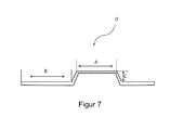
- the advantage according to the invention therefore manifests itself in the fact that, using external pressure, the surface element is plastically deformable in one, two or three dimensions and the luminance, in particular an embossed surface A and / or a background surface B (see, for example, US Pat FIG. 7 ), before and after the plastic deformation is substantially the same.
- an electroluminescent license plate with a flat, transparent electrode having one or more of the above features as a front electrode, with a luminescent layer with a matrix with luminescent particles that luminesce under the action of an AC electric field, and optionally with at least a dielectric layer and with a flat rear electrode, wherein the back electrode at least partially corresponds to the base body of the license plate or is applied to the base body, and the back electrode, the front electrode and / or the base body on the outwardly and / or internally facing side with an electrical insulating layer are provided.
- this can License plate also have a multi-layer structure explained above, in order to increase the luminance or to allow multi-colored illumination of the license plate.
- the license plate has on the front side on the electrode a foil or a coating for insulation and / or as a protective layer against dirt, scratches or chemical influences.
- this film may also be reflective, better retroreflective. The same applies to the outside of the return electrode.
- Self-adhesive films may also be considered as films in order to apply the license plate to transparent holders on the side of the front electrode or on another holder on the side of the rear electrode.
- the back electrode is provided on one side with a PE film on the surface facing the release layer.
- the outer surface of the back electrode may be provided with any suitable foil or coating. These can be applied in a further preceding or subsequent step to the front electrode and / or back electrode as a protective and / or insulating coating.
- front and / or rear electrodes provided with foils or coatings. Depending on the purpose, they protect and / or insulate the later outer side of the electrodes or serve as a dielectric between the electrodes. Further insulating layers or coatings on one or both sides of the flat front electrode and / or back electrode may be advantageous depending on the later application.
- a reflective film, better retroreflective sheeting, in particular a transparent reflective foil or better retroreflective sheeting, to the surface element according to the invention is particularly preferred, namely the reflective sheeting or better retroreflective sheeting preferably on the outside of the front electrode, optionally with intermediate layer and / or outer protective layer , applied.
- the electroluminescent license plate according to the invention is provided with a reflection foil, in particular a transparent reflection foil, preferably the front electrode is provided on its outwardly facing surface, optionally with an intermediate layer, with this reflection foil.
- the reflective films preferably meet the requirements or standards for license plates.
- the surface element or the license plate can be punched, packaged and / or embossed.
- the separating layers can be removed after the second step has been carried out or continue to remain on the surface element or on the license plate as protection during further processing.
- the invention further relates to the use of the electrode according to the invention with one or more of the aforementioned features as a transparent front electrode an electroluminescent surface element, such as an EL lamp, and / or as a transparent front electrode of a license plate, with the features set out above, or a solar cell.
- the surface element is deformable as a whole. This is achieved in that the surface element has a particularly deformable luminescent layer or further layers.
- the formability of the layers may result from the use of certain polymer compositions containing the layers.
- the polymer composition it is necessary for the polymer composition to be based on elastomers and / or of plastic polymers.
- Elastomers are elastically deformable and dimensionally stable polymers having a glass transition temperature below room temperature.
- a body made of an elastomer elastically deforms under an applied deformation force, but returns to its original undeformed shape when the deformation force ceases. This includes in the sense of the application also viscoelastic polymers that have a behavior that is partly elastic and sometimes viscous, so that the body after the loss of deformation only partially (incompletely) returns to its original shape and the remaining deformation energy then within a viscous flow process is degraded.
- a plastic polymer refers to polymers which deform plastically under the action of a deformation force, the deformation remaining completely or at least partially even after the deformation force ceases to exist.
- a polymer composition used and / or the electroconductive ink, varnish or ink each at an elongation rate of 300 mm / min should have an elongation at break of more than 20%, in particular more than 50% or even more than 100% and also have a tensile elastic modulus of less than 1000 MPa or even at most 100 MPa.
- the elongation at break (elongation at break) is a measure of the mechanical strength and deformability of materials. This material characteristic gives the lasting one percent change in length of a specimen (in relation to its initial length) that it has at break due to mechanical overload.
- the tensile strength describes the resistance of a body, in the present case - in particular a body - of the electrically conductive material of the element, against tensile forces (also tensile strength). This term is also used to define the maximum tensile stress as the force per unit of cross-sectional area (measured in Newton per square centimeter or Newton per square millimeter) that a body can withstand until fractured.
- the tensile strength is the maximum weight load during the tensile test, based on the support cross section, here inter alia of the electrically conductive material of the element, this may be the wire cross section, in the initial state (width times thickness).
- the tensile strength is related to a body of a material having a cross section of 1 mm 2 .
- the electrically conductive material of the element at room temperature (20 to 25 ° C) has a tensile strength between 5 to 2500 N / mm 2 , according to DIN EN 6892-1, in particular, the tensile strength of the electrically conductive material, in particular a body of this material, with a cross section of 1 mm 2 corresponding values in this area.
- DIN EN 6892-1 The disclosure content of DIN EN 6892-1 is referred to in its entirety and made the content of this document.
- Tensile strength or maximum force are according to DIN EN ISO 6892-1 according to point 3.9 and point 3.10.1.
- the measurement is carried out according to DIN EN ISO 6892-1 point 6.2-c (wire rod profiles smaller ⁇ 4 mm), method A (test speed based on the expansion rate control according to point 10.3).
- the test methods are carried out at room temperature.
- DIN EN ISO 6892-1 for metallic materials replaces the previously valid DIN EN 10002-1.
- the tensile strength is not only influenced by the material, but can also be influenced by its pre-treatment and its shape. Thus, the greatest tensile strengths are achieved with engineering materials that have been carefully heat treated and are in the form of fine wires.
- An example of this is steel alloys, especially in the form of fine wires.
- tensile strength is around 370 N / mm 2 for steel (St 37), and generally for wires tensile strengths between 100 and 2 060 N / mm 2 (Newton per square millimeter) are possible, preferably for stainless steels from 1373 to 2060 N /. mm 2 .
- DIN EN 6892-1 In addition to DIN EN 6892-1, such as explained above, to the old DIN EN 1002, which was partially replaced by the DIN EN 6892-1, and in addition to the DIN EN ISO 527-1 / -2 / -3 for plastics, partial replacement for DIN 53455/7, on DIN EN ISO 1924-2, DIN EN ISO 13934-1, DIN EN ISO 13934-2 (maximum tensile strength and maximum tensile strength of textile fabrics), DIN EN ISO 7500, DIN 29073-3 (maximum tensile strength and elongation of nonwovens) and ISO 5081 ( Maximum tensile strength and maximum tensile strength of textile fabrics).
- DIN EN 6892-1 concerns the test method for metal wires.
- the tensile elastic modulus (modulus of elasticity, tensile modulus, coefficient of elasticity, Young's modulus) is a material characteristic value by means of which the relationship between stress and strain is described during the deformation of a material with linear elastic behavior.
- the tensile elastic modulus in the present case is understood to mean the initial tensile elastic modulus at the onset of the tensile load.
- the amount of elastic modulus is greater, the more resistance a material opposes to its deformation.
- the stiffness of a concrete body made of this material also depends on the processing and on the geometry of the body.
- Elongation at break and tensile elastic modulus and tensile strength for plastics are determined according to DIN EN ISO 527-3 at room temperature with a defined test specimen (type 5) for a strain rate of 300 mm / min.
- the disclosure content of DIN EN ISO 527-3 is referred to in its entirety and made the content of this document.
- DIN ISO 527-1 describes methods for determining the tensile properties of plastics and plastic composites. In order to determine the properties of the electrically conductive materials according to the invention, DIN EN ISO 6892-1 is therefore applied to metallic materials and to DIN EN ISO 527-3 for plastics.
- FIG. 1 is the processing under the action of heat and pressure in a laminator (7) shown.
- a laminator for this purpose, first the PET / aluminum foil with the aluminum coating on top is laminated together with a transfer tape (luminescent layer provided with release foil on top side, foil of bottom side is thawed 8) between two release papers (6, TP, processing aid) by pushing the upper release paper into the laminator together with the lower release paper.
- the upper release paper is held up and the downwardly open transfer tape (first release film is uncovered) brought into contact with the PET / aluminum foil.
- the transfer tape is kept away from the aluminum foil for as long as possible.
- the second side of the transfer tape is also covered (upper release film).
- the PET / aluminum film is presented with an upwardly open luminescent layer of adhesive and electroluminescent particles and instead of the transfer tape from the first lamination step, the metallic fabric or the ITO film is then laminated to the open adhesive surface.
- the conductive coating faces the luminescent layer.
- FIG. 2a shows between the two release papers (6) a surface element according to the invention (0) with a transparent fabric electrode (1), an underlying luminescent layer (2) and the adjacent aluminum foil with PET layer on the underside .
- FIG. 2b is a surface element with an ITO film (9) shown, which can be used in the subsequent embossing tests.
- both the wire thickness of the fabric as well as the mesh size can be further optimized to achieve even better results in the luminance with simultaneous embossability of the surface element.
- the optimum for a wire diameter of around 25 ⁇ m is between 20 and 70 ⁇ m at mesh sizes, with even higher luminance densities being achieved with mesh sizes between 20 and 60 ⁇ m.
- FIG. 5 An embossing tool according to DIN 74069 and an EL lamp (A2) with a surface area of 60 mm x 80 mm, which is mounted on a 1 mm thick aluminum plate (A3, FIG. 5 ; Basic body (4), FIG. 6 ) is applied. Embossing takes place for 10 seconds when cold with the embossing tool.
- a large B with dimensions of 46 mm x 72 mm and an embossing depth of 2 mm is used.
- the sketch of the embossing tool in FIG. 5 shows as A4 a section of the surface of the lower embossing jaw and A3 a section of the surface of the upper embossing jaw as a cross-sectional view. The section shows one of the lines that are part of the letter B.
- FIG. 6 is a license plate (5) with a base body (4) and the surface element (0) shown before the embossing.
- the license plate has further unillustrated coatings or films on top to protect the electrode from damage and environmental influences.
- the effect according to the invention of the transparent, planar electrode in the planar element manifests itself after a one-, two- or three-dimensional plastic deformation of the planar element (0) in that the luminance of the planar element is substantially unchanged.
- the use of the electrode according to the invention causes no cracks in the electrode during the plastic deformation and the homogeneity of the AC voltage field essentially does not change.
- the advantage of the electrode (1) according to the invention is shown by embossing a surface element (0), as in FIG FIG. 7 shown schematically in that the luminance of the surface element (0) after a one-, two- or three-dimensional plastic deformation is substantially equal.
- the luminance of the embossed surface (A) and / or the background surface (B) having an embossing height (C) before and after the plastic deformation is substantially the same.
- Example 1 for producing a matrix for the luminescent layer
- a conventional 200 L reactor was charged with 4900 g of acrylic acid, 51 kg of 2-ethylhexyl acrylate, 14 kg of methyl acrylate and 53.3 kg of acetone / gasoline / isopropanol (48.5: 48.5: 3).
- the reactor was heated to 58 ° C and 40 g of 2,2'-Azoisobutter Aciditril (AIBN) was added.
- AIBN 2,2'-Azoisobutter Aciditril
- Example 2 An alternative, particularly preferably usable matrix for producing the luminescent layer is disclosed in Example 2.
- a cyanoacrylate-based pressure-sensitive polymer which has a relative planivity of more than 4.5, in a glass reactor with a capacity of 2 L, 300 g of a mixture of 3% by weight (3 mass or weight percent) of acrylic acid, 50% by weight of 2-cyanoacrylate and 47% by weight of 2-ethylhexyl acrylate in 300 g of a solvent mixture of acetone and isopropanol in a ratio of 90:10. After degassing the reaction solution at The nitrogen was passed through with stirring for 45 minutes while stirring to a temperature of 58 ° C.
- the adhesive compositions prepared as described above were solid-blended with 50% by weight of EL particles, based on the polymer, and applied by means of a comma bar to a siliconized polyester release film having a thickness of 50 ⁇ m so that the dry film thickness was 42 ⁇ m.
- the sample was dried in a drying oven at 120 ° C. for 15 minutes and covered with a further 36 ⁇ m thick siliconized release film until further processing.
- the two siliconized polyester films are only for processing the transfer tape and will not remain later in the target article.
- Example 1 The adhesive of Example 1 was used to prepare the examples below.
- the laminator "Ibico Pouchmaster 18 pro” is used.
- the samples are laminated at 175 ° C and at a speed of 0.7 m / min. Size of the patterns: Tissue: 10.75 cm x 6.0 cm ITO: 10.75 cm x 6.0 cm PET / Al: 10.75 cm x 7.0 cm
- the second release film of the transfer tape is uncovered and moved as in the first lamination step.
- the PET / AL film with an upwardly open layer of adhesive and EL particles is located on the lower TP and instead of the transfer tape the flat, transparent electrode in the form of a metallic fabric made of a steel 1.4401 or 1.4301 (see table 1, FIG. 2a ) or the ITO (see Table 1, FIG. 2b ) Film laminated to the open adhesive surface.
- the difference in luminosity when using the two different steel fabrics is not significant.
- tissue 25 25 54 34.8 29.4 1.4401 38 2.60 4 tissue 50 36 83 41.0 22.9 1.4401 39 2.02 3 tissue 100 65 157 48.9 19.6 1.4301 41 0.74 5 tissue 150 100 200 47.0 16.9 1.4301 40 0.64 7 tissue 250 100 226 60.1 12.5 1.4301 40 0.31 2 tissue 250 100 226 60.1 12.5 1.4301 40 3.02 8th ITO PET film Ref. 1 - - 175 73.3 2.0 PET / ITO 39 12,00 1
- the wire thickness of the fabric as well as the mesh size can be further optimized to further increase the luminance and at the same time to ensure the embossability of the surface element.
- Another starting point for improving the luminance is the combined use of optimized transparent, flat electrodes, more preferably of metallic fabrics or even polymeric fabrics with a conductive coating and with an EL-PSA with an even higher dielectric constant. By these measures considerably larger luminances are achievable.
- the interstices between the Electrode be provided with a conductive polymer composition, as explained below.
- particularly advantageous embodiments of the surface element are produced by filling in the intermediate spaces of the metal fabric with an organic flexible coating, for example of Baytron®, in order to make the electric field more homogeneous. In a more homogeneous field, a higher luminosity can be achieved.
- an organic flexible coating for example of Baytron®
- the luminosity increases by a factor of 10 to 3.02 cd / m 2 (see Table 1).
- the Baytron FE solution is a solution of poly (3,4-ethylenedioxythiophene) -poly (styrenesulfonate) in a mixture of water and ethanol.
- the electrode according to the invention as such can be provided directly with a conductive polymer composition.
- Table 2 example mesh d wire open area T L 100V [cd / m 2 ] [ ⁇ ] [ ⁇ ] [%] [%] row 1 1 25,00 25,00 25,00 34,80 2.60 2 40,00 25,00 37.87 46.21 4.67 3 50,00 28,00 41.09 49,20 3.67 4 70,00 25,00 54.29 61.44 1.98 5 100.00 25,00 64,00 70.44 1.34 6 150.00 25,00 73.47 79.23 0.82 7 200.00 25,00 79.01 84.37 0.41 Row 2 8th 40,00 15.00 52.89 56.65 5.92 9 40,00 18,00 47.56 55,20 5.63 10 40,00 23.00 40.31 48,50 4.89 11 40,00 25,00 37.87 47,60 4.67 12 40,00 28,00 34,60 43.30 3.49 13 40,00 36,00 27,70 37.50 2.26 Row 3 14 40,00 18,00 47.56 55,20 7.19 15 40,00 25,00 37.87 46.21 5.73 16 40,00 36,00 27,70 36.78 3.12
- the manufacture of the lamp is carried out according to rows 1 to 2 and the lamination described above. After the last step, the application of the metal mesh, a 4 wt .-% Baytron FE solution is coated on the surface of the lamp with a wire squeegee. The wet film thickness is 10 ⁇ m. The lamp is dried for 10 minutes at 110 ° C in a drying oven.
- Table 3 Devices for luminance determination device Manufacturer Type voltage source HBS Electronic GmbH ACS Power Source Luminance meter Gossen Mavo-Monitur UBS Table 4: Lamp manufacturing equipment device Manufacturer Type Laminator ibico pouchMaster 18pro
- the values for transmission and haze were measured on a Hazegard Plus from Byk Gardner.
- the samples were irradiated vertically and the transmitted light in an integrating sphere (Ulbrichtkugel) measured by photoelectric means.
- the spectral sensitivity is adapted to the CIE standard spectral value function Y under standard light C.
Abstract
Description
Die Erfindung betrifft eine flächige, zumindest teilweise transparente und tiefziehfähige Elektrode, die ein flächiges Element mit einem elektrisch leitenden Material umfasst. Die Elektrode eignet sich hervorragend für plastisch verformbare elektrolumineszierende Flächenelemente, so dass die Erfindung auch diese Flächenelemente betrifft sowie die Verwendung einer solchen Elektrode in elektrolumineszierenden Kennzeichenschildern.The invention relates to a planar, at least partially transparent and deep-drawing electrode comprising a sheet-like element with an electrically conductive material. The electrode is outstandingly suitable for plastically deformable electroluminescent surface elements, so that the invention also relates to these surface elements and the use of such an electrode in electroluminescent license plates.
Bislang werden Elektroden in vielen technischen Bereichen eingesetzt, um entweder einen Stromfluss in verschiedensten Materialen oder um den Aufbau eines elektrischen Feldes in verschiedensten Materialien zu ermöglichen. Dazu werden mindestens zwei Elektroden an eine Spannungsquelle angeschossen. Im einfachsten Fall können diese Elektroden aus zwei einfachen Metalldrähten bestehen.So far, electrodes have been used in many technical fields to either allow a current flow in a variety of materials or to build up an electric field in a variety of materials. For this purpose, at least two electrodes are connected to a voltage source. In the simplest case, these electrodes may consist of two simple metal wires.
Besonders anspruchsvoll ist die Aufgabe, Elektroden bereitzustellen, die gleichzeitig transparent und flächig ausgedehnt sind. Bisher werden derartige flächige und transparente Elektroden durch dünne Schichten aus organischen leitfähigen Polymeren, wie Polythiophenderivaten, oder anorganischen leitfähigen Beschichtungen, wie ITO (Indiumzinnoxid), hergestellt. Alle diese dem Fachmann bekannten Beschichtungen haben aufgrund ihrer Brüchigkeit eine unzureichende Flexibilität, einen hohen Preis, einen hohen Widerstand und sind nur zusammen mit einem Trägermaterial verfügbar und bearbeitbar. Insbesondere die mangelnde chemische und thermische Stabilität dieser Beschichtungen stellen eine besonders starke Einschränkung bei ihrer Anwendung dar. Die unzureichende Resistenz von leitfähigen Beschichtungen wie ITO im Verbund mit anderen organischen Materialien, die Restmonomere und/oder Restlösungsmittel enthalten, ist dem Fachmann ausreichend bekannt. All diese flächigen und transparenten Elektroden eignen sich aufgrund ihrer Brüchigkeit nicht für eine Anwendung, die einen Prägeprozess oder einen Tiefziehprozess beinhalten, wie beispielsweise bei der Herstellung von Kennzeichenschildern für Kraftfahrzeuge. Beispielsweise ist aus der
Herkömmliche Kennzeichenschilder für Kraftfahrzeuge werden aus einem Blechrohling hergestellt, der mit einer reflektierenden Schicht versehen ist und geprägt wird, um die entsprechende Individualisierung mittels einer Buchstaben- und/oder Nummernkombinationen zu ermöglichen. Nach dem Prägen werden die Blechrohlinge einem Heißwalzfärbeverfahren zum Einfärben der geprägten Buchstaben- und/oder Nummernkombinationen unterzogen. Gegebenenfalls wird auf die fertigen Schilder eine transparente Schutzschicht aufgebracht.Conventional license plates for motor vehicles are made from a sheet metal blank, which is provided with a reflective layer and is embossed to allow the corresponding individualization by means of a combination of letters and / or numbers. After embossing, the sheet blanks are subjected to a hot roll dyeing process for coloring the embossed character and / or number combinations. Optionally, a transparent protective layer is applied to the finished signs.
Nachteilig ist, dass zur guten Erkennbarkeit der Buchstaben- und Nummernkombinationen in der Dunkelheit in unmittelbarer Nähe des Kennzeichenschildes am Fahrzeug eine Lichtquelle angeordnet werden muss, die das Schild beleuchtet, damit die einfallenden Lichtstrahlen reflektiert werden können.The disadvantage is that for good visibility of the letter and number combinations in the dark in the immediate vicinity of the license plate on the vehicle, a light source must be arranged, which illuminates the shield so that the incident light rays can be reflected.
Aus der
Sogenannte Elektolumineszenz-Lampen (EL-Lampen) bestehen aus einer unteren Elektrode, einer Leuchtschicht aus Matrix und Leuchtpartikeln, einem Dielektrikum und einer oberen Elektrode. Die einzelnen Schichten werden üblicherweise sukzessive im Siebdruck aufeinander aufgebaut. Für den Druck kommen handelsübliche Pasten zum Einsatz. Die bekannten Pasten haben den Nachteil, dass die aufgetragene Schicht nach dem Drucken und Trocknen extrem spröde und brüchig ist und bei Luftfeuchtigkeit die Verbundfestigkeit verliert.So-called electroluminescent lamps (EL lamps) consist of a lower electrode, a luminescent layer of matrix and luminous particles, a dielectric and an upper electrode. The individual layers are usually built successively screen-printed on each other. Commercially available pastes are used for printing. The known pastes have the disadvantage that the applied layer after The printing and drying is extremely brittle and brittle and loses the bond strength at atmospheric moisture.
In einem Tiefziehprozess, wie er beispielsweise für die Prägung von KFZ-Nummernschildern nötig ist, wird der Verbund der Schichten daher zerstört und die herkömmlichen Elektroden beziehungsweise deren leitfähige Beschichtungen brechen, so dass nicht leuchtende Areale entstehen.In a deep-drawing process, as is necessary, for example, for embossing license plates, the composite of the layers is therefore destroyed and the conventional electrodes or their conductive coatings break, so that non-luminous areas are formed.
Ein verformbares, beziehungsweise prägefähiges Schild, insbesondere ein Kennzeichen für Kraftfahrzeuge mit einem Elektrolumineszenz-Aufbau, ist aus der
Davon ausgehend ist es die Aufgabe der Erfindung, eine transparente, flächige Elektrode bereitzustellen, die einen niedrigen elektrischen Widerstand und zugleich eine hohe Flexibilität aufweist, kostengünstig herstellbar ist und eine hohe chemische Widerstandsfähigkeit besitzt. Insbesondere soll sie ohne einen zusätzlichen Träger von Rolle zu Rolle verarbeitet werden können. Eine weitere Aufgabe der Erfindung ist die Bereitstellung eines tiefziehfähigen elektrolumineszierenden Flächenelementes basierend auf der erfindungsgemäßen Elektrode.On this basis, it is the object of the invention to provide a transparent, flat electrode, which has a low electrical resistance and at the same time a high flexibility, can be produced inexpensively and has a high chemical resistance. In particular, it should be able to be processed without an additional carrier from roll to roll. Another object of the invention is to provide a deep drawable electroluminescent surface element based on the electrode according to the invention.
Völlig überraschend kann die Aufgabe der Erfindung mit einer flächigen, zumindest teilweise transparenten und tiefziehfähigen, insbesondere trägerlosen, Elektrode gelöst werden, die ein flächiges Element umfasst mit einem elektrisch leitenden, insbesondere Metall enthaltenden Material, und das elektrisch leitende Material bei Raumtemperatur, das heißt bei 20 bis 25 °C, bevorzugt bei 20 °C, eine Reißdehnung oder synonym Bruchdehnung, insbesondere nach DIN EN ISO 6892-1, Punkt 3.4.2, zwischen 1 und 70 % oder auch über 70 % und eine Zugfestigkeit zwischen 5 bis 2500 N/mm2, insbesondere nach DIN EN 6891-1, aufweist und das flächige Element eine Schicht eines elektrisch leitenden Materials mit transparenten, flächigen Ausnehmungen oder ein flächiges Gitternetz mit mindestens einem elektrisch leitenden Filament des Materials ist. Gemäß einer besonders bevorzugten Ausführungsform der vorliegenden Erfindung umfasst die Elektrode zusätzlich zu den vorstehend oder nachstehend genannten Merkmalen zwei Mittel zur Kontaktierung, beispielsweise Metallkontakte oder Kontaktierungsstellen. Unter Transparenz ist erfindungsgemäß eine flächige optische Durchgängigkeit zu verstehen, das die Elektrode bildende Material selbst muss nicht transparent sein.Quite surprisingly, the object of the invention can be achieved with a flat, at least partially transparent and thermoformable, in particular carrierless, electrode comprising a sheet-like element with an electrically conductive, in particular metal-containing material, and the electrically conductive material at room temperature, that is at 20 to 25 ° C, preferably at 20 ° C, an elongation at break or synonymous elongation at break, in particular according to DIN EN ISO 6892-1, point 3.4.2, between 1 and 70% or even over 70% and a tensile strength between 5 to 2500 N. / mm 2 , in particular according to DIN EN 6891-1, and the planar element is a layer of an electrically conductive material with transparent, flat recesses or a flat lattice with at least one electrically conductive filament of the material. According to a particularly preferred embodiment of the present invention, in addition to the features mentioned above or below, the electrode comprises two contacting means, for example metal contacts or contacting points. Under transparency according to the invention is to be understood a planar optical continuity, the material forming the electrode itself need not be transparent.
Die genannten Zugfestigkeiten der elektrisch leitenden Materialien, beispielsweise der nachfolgend genannten Metalle oder Legierungen, insbesondere als Rohmaterialien, wird nach DIN ISO 6892-1 ermittelt, wobei die Zugefestigkeit der Höchstkraft entsprechend DIN EN ISO 6892-1 Punkt 3.9 und Punkt 3.10.1 entsprechen kann. Die Messung erfolgt gemäß dem Verfahren in Punkt 6.2-c (Draht-Stäbe-Profile kleiner < 4mm), Verfahren A (Prüfgeschwindigkeit basierend auf Dehngeschwindigkeitsregelung nach Punkt 10.3). Auf den Offenbarungsgehalt der DIN EN ISO 6892-1 sowie aller weiteren genannten DIN wird vollständig Bezug genommen und ihr Inhalt zum Inhalt dieses Dokumentes gemacht.The mentioned tensile strengths of the electrically conductive materials, for example the metals or alloys mentioned below, in particular as raw materials, are determined according to DIN ISO 6892-1, whereby the tensile strength can correspond to the maximum force according to DIN EN ISO 6892-1 point 3.9 and point 3.10.1 , The measurement is carried out according to the procedure in item 6.2-c (wire rod profiles smaller <4mm), method A (test speed based on the expansion rate control according to item 10.3). The disclosure content of DIN EN ISO 6892-1 as well as all other DINs mentioned is referred to in their entirety and their contents are included in the content of this document.
Die Reißdehnung oder synonym die Bruchdehnung des Materials, des flächigen Gitternetzes als auch der Schicht des flächigen Elements sollten möglichst hoch sein, um eine schadlose Verformbarkeit der Elektrode, insbesondere des Gewebes, beim Prägeprozess zu ermöglichen.The elongation at break or synonymously the elongation at break of the material, of the flat lattice network as well as of the layer of the planar element should be as high as possible in order to enable harmless deformability of the electrode, in particular of the fabric, during the embossing process.
Daher ist es bevorzugt, wenn die Reißdehnung des Material zwischen 3 bis 70 %, insbesondere zwischen 10 bis 70 %, besonders bevorzugt zwischen 12 bis 70 %, oder noch besser zwischen 18 bis 70 % liegt und es eine Zugfestigkeit zwischen 5 bis 2100 N/mm2, insbesondere zwischen 12 bis 2100 N/mm2, besser zwischen 50 bis 2100 N/mm2, besonders bevorzugt zwischen 40 bis 2000 N/mm2, aufweist. Auch Materialien mit Zugfestigkeiten zwischen 45 bis 560 N/mm2 sind besonders bevorzugt. Typische bevorzugte Materialien weisen vorzugsweise Werte zwischen 40 MPa und 1300 MPa auf (70 N/mm2 bis 2000 N/mm2). So können bevorzugte Materialien, wie Aluminium enthaltenden Legierungen oder Stähle, Zugfestigkeiten von 16 bis 600 N/mm2 bei einer Reißdehnung von 16 bis 50 % aufweisen. Auch Kupfer ist bevorzugt und kann je nach Verarbeitung eine Zugfestigkeit von 200 bis 400 N/mm2 bei den genannten Reißdehnungen aufweisen. Zu den genannten Materialien zählen eine Reihe von Metallen und deren Legierungen. Die Zugfestigkeit beschreibt den Kraftaufwand der nötig ist, um eine bestimmte Verformung zu erreichen. Je niedriger der Kraftaufwand ist, desto besser ist das Metallgewebe für die Verformbarkeit geeignet. Erfindungsgemäß weisen die Materialien der Gewebe, ob als Metallgewebe oder auch als Gewebe polymerer metallbeschichteter Drähte, daher die vorgenannten duktilen Eigenschaften auf.Therefore, it is preferred if the elongation at break of the material is between 3 to 70%, in particular between 10 to 70%, particularly preferably between 12 to 70%, or even better between 18 to 70% and if there is a tensile strength between 5 and 2100 N / mm 2 , in particular between 12 to 2100 N / mm 2 , more preferably between 50 to 2100 N / mm 2 , particularly preferably between 40 to 2000 N / mm 2 . Also materials with tensile strengths between 45 to 560 N / mm 2 are particularly preferred. Typical preferred materials preferably have values between 40 MPa and 1300 MPa (70 N / mm 2 to 2000 N / mm 2 ). Thus, preferred materials, such as aluminum-containing alloys or steels, may have tensile strengths of 16 to 600 N / mm 2 with an elongation at break of 16 to 50%. Copper is also preferred and, depending on the processing, may have a tensile strength of 200 to 400 N / mm 2 at the mentioned elongations at break. The materials mentioned include a number of metals and their alloys. The tensile strength describes the force required to achieve a certain deformation. The lower the effort, the better the metal fabric is suitable for deformability. According to the invention, the materials of the fabric, whether as a metal fabric or as a fabric of polymeric metal-coated wires, therefore, the aforementioned ductile properties.
Als Materialien kommen beispielsweise Aluminium oder auch Legierungen des Aluminiums mit einem Gehalt an Magnesium in Betracht. Bevorzugte Aluminium enthaltende Legierungen weisen Zugfestigkeiten von 60 bis 400 N/mm2 bei einer Bruchdehnung von 20 bis 40 % in Abhängigkeit von der Zusammensetzung auf. Weitere geeignete Legierungen können Legierungszusätze, die die Festigkeit beeinflussen, enthalten, dies sind beispielsweise neben Magnesium auch Zink, Silizium oder Mangan. Dabei weiß der Fachmann, dass auch die Verarbeitung der Metalle oder der Legierungen deren Materialeigenschaften beeinflusst. Generell sind daher Materialien bevorzugt, deren Reißdehnung im Bereich zwischen 10 bis 70 % und/oder deren Zugfestigkeit zwischen 50 bis 2100 N/mm2 oder im Bereich auch zwischen 12 bis 1000 N/mm2 liegt, besonders vorzugsweise liegt die Reißdehnung im Bereich zwischen 15 bis 55 % und/oder die Zugfestigkeit zwischen 12 bis 1000 N/mm2.Suitable materials include, for example, aluminum or alloys of aluminum containing magnesium. Preferred aluminum-containing alloys have tensile strengths of 60 to 400 N / mm 2 at an elongation at break of 20 to 40%, depending on the composition. Other suitable alloys may contain alloying additives that affect the strength, for example, in addition to magnesium and zinc, silicon or manganese. The expert knows that the processing of metals or alloys also influences their material properties. In general, therefore, materials are preferred whose elongation at break in the range between 10 to 70% and / or their tensile strength between 50 to 2100 N / mm 2 or in the range between 12 to 1000 N / mm 2 , particularly preferably the elongation at break in the range between 15 to 55% and / or the tensile strength between 12 to 1000 N / mm 2 .
Ferner ist es bevorzugt, wenn die Reißdehnung und der Zug-Elastizitätsmodul des flächigen Elementes, insbesondere des flächigen Gitternetzes oder der flächigen Schicht, bei einer Dehngeschwindigkeit von 300 mm/min und einer Temperatur von 23 °C eine Reißdehnung von mehr als 20 % aufweist, insbesondere von mehr als 50 % oder sogar von mehr als 100 %, und außerdem ein Zug-Elastizitätsmodul von weniger als 1000 MPa oder sogar von höchstens 100 MPa besitzt.Furthermore, it is preferred if the elongation at break and the tensile modulus of elasticity of the planar element, in particular the two-dimensional grid or the planar layer, has an elongation at break of more than 20% at a strain rate of 300 mm / min and a temperature of 23 ° C, especially more than 50% or even more than 100%, and also has a tensile elastic modulus of less than 1000 MPa or even not more than 100 MPa.
Ebenfalls Gegenstand der Erfindung ist eine flächige, zumindest teilweise transparente, tiefziehfähige Elektrode, die ein flächiges Element mit einem elektrisch leitenden Material umfasst, wobei das elektrisch leitende Material des Elements aus mindestens einem Metall, einer Legierung oder gegebenenfalls aus einem elektrisch leitfähigen Polymer ist und das flächige Element ein flächiges Gitternetz eines tiefziehfähigen Gewebes mit einer glatten Bindung, Körperbindung oder Leinwandbindung, insbesondere gemäß DIN-ISO 9044:2001-09, Punkt 3, mit mindestens einem elektrisch leitenden Filament des Materials umfasst. Erfindungsgemäß ist die tiefziehfähige Elektrode ein Metalldrahtgewebe wie nachfolgend definiert, oder ein Gewebe mit polymeren Filamenten, die Filamente zumindest teilweise mit einer elektrisch leitenden Beschichtung versehen sind. Gegenstand der Erfindung ist auch die Verwendung des genannten Gewebes als Elektrode, vorzugsweise für ein Flächenelement oder ein elektrolumineszierende Kennzeichenschild wie nachstehend detailliert dargelegt.Likewise provided by the invention is an areal, at least partially transparent, deep-drawable electrode which comprises a planar element with an electrically conductive material, wherein the electrically conductive material of the element is made of at least one metal, an alloy or optionally of an electrically conductive polymer and the flat element comprises a two-dimensional grid of a thermoformable fabric with a smooth bond, body binding or plain weave, in particular according to DIN-ISO 9044: 2001-09,
Eine derartige Elektrode ist hochverformbar und ist somit auch tiefziehfähig oder prägbar, ohne ihre Funktionalität zu vermindern. Dies beruht auf der speziellen Kombination des Materials und der speziellen Ausbildung des flächigen Elements. So muss das Material, insbesondere das Metall, das elektrisch leitfähige Polymer oder die Legierung, eine besonders hohe Reißdehnung und gleichzeitig eine typische Zugfestigkeit aufweisen. Infolge der Zugfestigkeit ist das Material hinreichend nachgiebig. Gleichzeitig muss es aber auch eine hohe Reißdehnung aufweisen, um insgesamt zerstörungsfrei verformbar zu sein. Nur Materialien, in denen die beiden erfindungsgemäßen Merkmale zugleich realisiert sind, sind in ausreichendem Maß verformbar, um sich ohne Einschränkung der Funktionalität tiefziehen oder prägen zu lassen und diese Eigenschaft auch nicht in einem Flächenelement mit Schichtaufbau einzubüßen.Such an electrode is highly deformable and is therefore also thermoformable or embossable without reducing its functionality. This is due to the special combination of the material and the special design of the sheet element. Thus, the material, in particular the metal, the electrically conductive polymer or the alloy, must have a particularly high elongation at break and at the same time a typical tensile strength. Due to the tensile strength, the material is sufficiently yielding. At the same time, however, it must also have a high elongation at break in order to be able to be deformed completely non-destructively. Only materials in which the two features according to the invention are realized at the same time are sufficiently deformable to be deep-drawn or embossed without restriction of the functionality and not to lose this property in a surface element with layer structure.
Die speziellen Ausführungsformen des flächigen Elements sehen zum einen eine Schicht eines elektrisch leitenden Materials mit transparenten, flächigen Ausnehmungen jedweder zweidimensionalen Form vor. Dies kann beispielsweise eine Schicht mit kreisförmigen, ovalen, rautenförmigen, sternförmigen, rechteckigen oder quadratischen Ausnehmungen sowie davon abgeleiteten zweidimensionalen Ausnehmungen sein. Die Schicht kann beispielsweise auf eine Leuchtschicht aufgedruckt werden, wobei das aufzudruckende Material die vorgenannte Reißdehnung und Zugfestigkeit aufweisen muss. Alternativ kann die Elektrode als flächiges Element in Form eines Gitternetzes oder als Schicht mit Ausnehmungen auf eine Transferfolie aufgedruckt werden und später mit der Leuchtschicht flächig verbunden werden. Anschließend kann die Transferfolie entfernt werden und gegebenenfalls durch eine isolierend wirkende Schicht ersetzt werden.The specific embodiments of the sheet-like element on the one hand provide a layer of an electrically conductive material with transparent, flat recesses of any two-dimensional shape. This may be, for example, a layer with circular, oval, diamond-shaped, star-shaped, rectangular or square recesses and two-dimensional recesses derived therefrom. The layer can be printed, for example, on a luminescent layer, wherein the material to be printed on the aforementioned elongation at break and tensile strength got to. Alternatively, the electrode can be printed as a flat element in the form of a grid or as a layer with recesses on a transfer film and later connected to the luminescent layer surface. Subsequently, the transfer film can be removed and optionally replaced by an insulating layer.
Gemäß einer besonders bevorzugten Ausführungsform ist das flächige Element der tiefziehfähigen Elektrode ein Gitternetz, insbesondere mit zwei Metallkontakten oder Kontaktierungsstellen. Als ein Gitternetz wird ein Netz aus Filamenten verstanden, die sich in der Regel im gleichen Abstand und in der Regel im Wesentlichen rechtwinklig kreuzen beziehungsweise schneiden. Erfindungsgemäß sind die Filamente im Wesentlichen gerade, parallel zu einander angeordnet und kreuzen beziehungsweise schneiden sich im Wesentlichen rechtwinklig, insbesondere mit weiteren gerade, parallel zu einander angeordneten Filamenten des Gitternetzes. Folglich sind die Filamente besonders bevorzugt entsprechend der Kette (alle parallel zur Webrichtung verlaufenden Drähte eines Drahtgewebes) und des Schusses (alle rechtwinklig zur Webrichtung verlaufenden Drähte eines Drahtgewebes) angeordnet (DIN ISO 9044:2001-09, 3. Begriffe). Als Webart kommen generell alle dem Fachmann bekannten Webarten für Gewebe oder Gitternetze in Betracht, wobei die glatte Bindung oder Körperbindung gemäß der Offenbarung in 3.8 der vorgenannten DIN-Norm, insbesondere mit Quadratmaschenform, bevorzugt sind. Die glatte Bindung wird auch bezeichnet als "Leinwandbindung" oder "Form A". Der gesamte Offenbarungsgehalt der DIN 9044:2001-09 wird zum Inhalt dieser Erfindung gemacht. Der Draht- oder Filamentdurchmesser (d) wird vorzugsweise entsprechend der DIN ISO 4782 gemessen. Dem Fachmann ist klar, dass die Filamente auch in unregelmäßigen oder mit definierten, abweichenden Abständen und/oder im stumpfen und/oder spitzen Winkel angeordnet sein können. Weitere mögliche Anordnungen der Filamente, insbesondere die Maschenformen, können neben Quadratmaschen auch Rechteckmaschen, auch bezeichnet als Lang-oder Breitmaschen, sein. Sofern sinnvoll kann jegliche Anordnung gewählt werden, insbesondere, wenn dadurch die elektrisch leitende Schicht flexibler wird, das heißt, unabhängiger von der Bruchdehnung und/oder der Zugfestigkeit des elektrisch leitenden Materials. Die Bestimmung der Reißdehnung und der Zugfestigkeit erfolgt an den zur Herstellung der flächigen Filamente, bevorzugt des Gitternetzes, verwendeten Materialien gemäß DIN ISO 6892-1 wie vorstehend erläutert.According to a particularly preferred embodiment, the planar element of the thermoformable electrode is a grid, in particular with two metal contacts or contacting points. A grid network is understood to be a network of filaments which usually intersect or intersect at the same distance and generally at right angles. According to the invention, the filaments are arranged essentially straight, parallel to one another and intersect or intersect substantially at right angles, in particular with further straight filaments of the grid network arranged parallel to one another. Consequently, the filaments are particularly preferably arranged according to the warp (all wires of a wire fabric running parallel to the weaving direction) and the weft (all wires of a wire cloth running at right angles to the weaving direction) (DIN ISO 9044: 2001-09, 3rd terms). As a weave, in general, all weaves or meshes known to those skilled in the art may be considered, with the smooth weave or body weave according to the disclosure in 3.8 of the abovementioned DIN standard, in particular with square mesh form, being preferred. The smooth weave is also referred to as "plain weave" or "form A". The entire disclosure content of DIN 9044: 2001-09 is made part of the content of this invention. The wire or filament diameter (d) is preferably measured according to DIN ISO 4782. It is clear to the person skilled in the art that the filaments can also be arranged at irregular or at defined deviating distances and / or at an obtuse and / or acute angle. Other possible arrangements of the filaments, in particular the mesh forms, may be square meshes as well as rectangular meshes, also referred to as long or wide meshes. If appropriate, any arrangement can be chosen, especially if this makes the electrically conductive layer more flexible, that is, more independent of the elongation at break and / or the tensile strength of the electrically conductive material. The determination of the elongation at break and the tensile strength is carried out on the materials used for producing the flat filaments, preferably of the grid, according to DIN ISO 6892-1 as explained above.
Erfindungsgemäß ist die flächige, transparente Elektrode ein Metalldrahtgewebe, insbesondere aus Stahl, wie beispielsweise 1.4401 oder 1.4301 Stahl. Die Gewebe wurden für die nachstehenden Versuche von den Firmen Wolfgang-H Schutz GmbH, Mechernich-Vussem oder Haver & Boecker, Oelde angefertigt. Durch Verwendung von ausreichend dünnen Drähten in den Metallgeweben kann eine hohe Transparenz bei geringer Maschenweite erzielt werden, insbesondere bei Geweben gemäß einer Anordnung der Filamente, wie sie in der DIN 9044:2001-09 offenbart ist. Als Material der Metallgewebe eignen sich generell alle leitfähigen Metalle und deren Legierungen, wie beispielsweise Aluminium, Kupfer, Eisen, Silber, Gold, Zink, Wolfram, Chrom, Blei, Titan, Nickel, Platin und Gadolinium. Eine bevorzugte Legierung ist neben Eisen, Kupfer und/oder Aluminium haltigen Legierungen auch Nitinol.According to the invention, the flat, transparent electrode is a metal wire mesh, in particular of steel, such as 1.4401 or 1.4301 steel. The fabrics were made by the companies Wolfgang-H Schutz GmbH, Mechernich-Vussem or Haver & Boecker, Oelde for the following experiments. By using sufficiently thin wires in the metal fabrics, a high transparency can be achieved with a small mesh size, in particular for fabrics according to an arrangement of the filaments, as disclosed in DIN 9044: 2001-09. As a material of the metal mesh are generally all conductive metals and their alloys, such as aluminum, copper, iron, silver, gold, zinc, tungsten, chromium, lead, titanium, nickel, platinum and gadolinium. A preferred alloy is in addition to iron, copper and / or aluminum-containing alloys and nitinol.
Besonders vorteilhaft sind Metalldrahtgewebe aus Metallen oder Legierungen, die eine hohe Duktilität aufweisen. Stahl kann sich bis zu 25 % plastisch verformen, bevor er reißt. Bei Gold ist die Duktilität um ein Vielfaches größer. Der Vorteil duktiler Werkstoffe besteht darin, dass eine gute kalte Verformbarkeit gegeben ist, was sich in einer hervorragenden Biegefähigkeit und Tiefziehfähigkeit äußert. Ferner weisen viele Metalle eine hohe Reflexion auf, dies wirkt sich positiv bei der Lichtdurchlässigkeit der Elektrode aus, da das Material nur einen geringen Anteil des Lichtes absorbiert. Materialien, die keine hohe Reflexion aufweisen werden daher bevorzugt mit stark regulär und/oder diffus reflektierenden Beschichtungen versehen, beispielsweise mit Nanopartikeln.Particularly advantageous are metal wire mesh made of metals or alloys which have a high ductility. Steel can deform plastically up to 25% before it breaks. For gold, the ductility is many times greater. The advantage of ductile materials is that they provide good cold ductility, which translates into excellent bending and deep-drawability. Furthermore, many metals have a high reflectivity, this has a positive effect on the light transmission of the electrode, since the material absorbs only a small portion of the light. Materials which do not have high reflectivity are therefore preferably provided with coatings which have a high degree of regular and / or diffuse reflection, for example nanoparticles.
Ein weiterer Vorteil der flächigen, transparenten Elektroden aus Metalldrahtgeweben ist, dass sie trägerlos hergestellt, gelagert und verarbeitet werden können, insbesondere können sie von Rolle zu Rolle verarbeitet werden.Another advantage of the flat, transparent electrodes of metal wire mesh is that they can be produced, stored and processed without straps, in particular they can be processed from roll to roll.
Besonders geeignete transparente Elektroden weisen zusätzlich zu den vorgenannten Merkmalen eine Transmission von 5 bis 92 % im Bereich des UV/Vis-Spektralbereichs auf, insbesondere von 20 bis 85 %, vorzugsweise von 40 bis 85 %, bevorzugt von 50 bis 85 %, besonders bevorzugt von 50 bis 80 % oder auch von 50 bis 75 %. Alternative zweckmäßige Bereiche können bei 5 bis 80 % im Bereich des UV/Vis-Spektralbereichs liegen, insbesondere von 10 bis 60 %, besser von 15 bis 55 %, vorzugsweise von 30 bis 55 %, bevorzugt von 20 bis 55 %, besonders bevorzugt von 25 bis 55 %. Hohe Werte bei der Transmission erhöhen die Leuchtdichte von elektrolumineszierenden Lampen mit diesen Elektroden.Particularly suitable transparent electrodes have, in addition to the abovementioned features, a transmission of 5 to 92% in the UV / Vis spectral range, in particular from 20 to 85%, preferably from 40 to 85%, preferably from 50 to 85%, particularly preferably from 50 to 80% or even from 50 to 75%. Alternative useful ranges may range from 5 to 80% in the UV / Vis spectral region, in particular from 10 to 60%, more preferably from 15 to 55%, preferably from 30 to 55%, preferably from 20 to 55%, most preferably from 25 to 55%. High values at the transmission increase the luminance of electroluminescent lamps with these electrodes.
Als besonders vorteilhafte, transparente und tiefziehfähige Elektroden haben sich jene herausgestellt, deren flächiges Element ein Gitternetz eines elektrisch leitenden Gewebes umfasst, beispielsweise ein elektrisch leitendes gewebtes Gitter oder ein aufdruckbares elektrisch leitendes Gitter mit im Wesentlichen regelmäßig parallel und/oder rechtwinklig, insbesondere mit einer Bindung der Filamente gemäß DIN 9044:2001-09, 3.8, oder meanderförmig angeordneten, elektrisch leitendenden Filamenten.Particularly advantageous, transparent and deep-drawing electrodes have been found to be those whose flat element comprises a grid of electrically conductive tissue, for example an electrically conductive woven grid or a printable electrically conductive grid with substantially regular parallel and / or rectangular, in particular with a bond the filaments according to DIN 9044: 2001-09, 3.8, or meandering arranged, electrically conductive filaments.
Erfindungsgemäß ist die transparente Elektrode ein elektrisch leitendes Gewebe aus einem vorgenannten Metall oder einer entsprechenden Legierung insbesondere gemäß DIN 9044:2001-09. In diesem Fall ist das flächige Gitternetz ein Metalldrahtgewebe aus einem Metall oder einer entsprechenden Metall enthaltenden Legierung, insbesondere mit einer vorgenannten Reißdehnung und Zugfestigkeit. Die Filamente sind bevorzugt in dem Metalldrahtgewebe gerade parallel und rechtwinklig zueinander angeordnet, insbesondere gemäß DIN 9044:2001-09, 3.8. Ein alternatives besonders bevorzugtes Gewebe ist ein polymeres Gewebe, das zumindest teilweise mit Metallen oder einer Legierung beschichtet ist oder das polymere Gewebe mindestens ein metallisches Filament umfasst. In jedem Fall weisen die erfindungsgemäßen Elektroden eine ein- oder zweidimensionale elektrische Leitfähigkeit auf. Vorzugsweise verfügt die Elektrode zusätzlich zu den vorstehend oder nachstehend genannten Merkmalen über zwei Metallkontakte oder Kontaktierungsstellen.According to the invention, the transparent electrode is an electrically conductive fabric of an aforementioned metal or a corresponding alloy, in particular according to DIN 9044: 2001-09. In this case, the sheet-like mesh is a metal wire mesh made of a metal or a corresponding metal-containing alloy, in particular with an aforementioned elongation at break and tensile strength. The filaments are preferably arranged in the metal wire mesh straight parallel and at right angles to each other, in particular according to DIN 9044: 2001-09, 3.8. An alternative particularly preferred fabric is a polymeric fabric that is at least partially coated with metals or an alloy, or that polymeric fabric comprises at least one metallic filament. In any case, the electrodes according to the invention have a one-dimensional or two-dimensional electrical conductivity. In addition to the features mentioned above or below, the electrode preferably has two metal contacts or contacting points.
Alternativ oder zusätzlich zu den vorgenannten Merkmalen hat es sich als besonders vorteilhaft herausgestellt, wenn das Gitternetz ein Gewebe mit Metall enthaltenden, elektrisch leitenden Drähten umfasst, die aus mindestens einem Metall oder einer Legierung sind, wie Metalldrahtgewebe, oder ein Gewebe mit polymeren Filamenten und die Filamente zumindest teilweise mit einer elektrisch leitenden Beschichtung versehen sind, die mindestens ein Metall, eine elektrisch leitende Legierung oder eine elektrisch leitende Polymermasse, wie Polyanilin, 1,3-diethylendioxide Derivate des Imidazolins oder EOIml-2,2, gegebenenfalls mit mindestens einem elektrisch leitenden Füllstoff, umfasst, wobei der Füllstoff ausgewählt sein kann aus der Gruppe Metallpartikel, umfassend Silber, Gold, Platin oder Aluminium und deren Legierungen oder Graphit, Kohlenstoff-Nanoteilchen, Kohlenstoff-Nanoröhren, Ruß, Leitruß, Fullerene, Fulleren-Derivate und Acetylen-Ruß. Vorzugsweise erfüllt die elektrisch leitende Polymermasse ebenfalls die Anforderungen an die Reißdehnung und/oder Zugfestigkeit der erfindungsgemäßen elektrisch leitenden Materialien, das heißt, sie liegen vorzugsweise etwa im gleichen Bereich der genannten Werte. Vorzugsweise decken die elektrisch leitenden Polymere ebenfalls mindestens den Bereich der Reißdehnung der genannten metallischen Materialien ab, das heißt, die Polymere sind mindestens so elastisch wie die metallischen elektrisch leitfähigen Materialien.Alternatively, or in addition to the above features, it has been found to be particularly advantageous if the grid comprises a fabric with metal-containing, electrically conductive wires, which are made of at least one metal or alloy, such as metal wire mesh, or a fabric with polymeric filaments and the Filaments are at least partially provided with an electrically conductive coating containing at least one metal, an electrically conductive alloy or an electrically conductive polymer composition, such as polyaniline, 1,3-diethylenedioxide derivatives of imidazoline or EOIml-2,2, optionally with at least one electrically conductive Filler, wherein the filler may be selected from the group of metal particles, comprising silver, gold, platinum or aluminum and their alloys or graphite, carbon nanoparticles, carbon nanotubes, carbon black, carbon black, fullerenes, fullerene derivatives and acetylene black. The electrically conductive polymer composition preferably also meets the elongation at break and / or tensile strength requirements of the electrically conductive materials according to the invention, that is to say they are preferably in the same range of the values mentioned. Preferably, the electrically conductive polymers also cover at least the range of elongation at break of said metallic materials, that is, the polymers are at least as elastic as the metallic electrically conductive materials.
Ferner ist es bevorzugt, wenn die flächige, transparente Elektrode, insbesondere mit zwei Metallkontakten oder Kontaktierungsstellen, die vorgenannten Reißdehnung und Zugfestigkeit aufweist und insbesondere zugleich einen Flächenwiderstand von unter 300 Ω, wie beispielsweise zwischen 0,001 bis 300 Ω, besser zwischen 0,0005 bis 300 Ω, bevorzugt zwischen 0,0001 Ω bis 300 Ω. Bevorzugt liegt der Flächenwiderstand unter 100 Ω, besonders bevorzugt unter 50 Ω, wobei noch bevorzugter ein Flächenwiderstand von unter 1,0 Ω, insbesondere unter 0,2 Ω, besonders bevorzugt unter 0,01 Ω, und insbesondere im Bereich bis 0,0005 Ω, bevorzugt bis 0,001 Ω. Generell sollen alle Werte des Flächenwiderstands zwischen 300 Ω bis 0 Ω als offenbart gelten. Diese Werte für den Flächenwiderstand gelten vorzugsweise sowohl für die auf metallischen und/oder auf polymeren Materialien basierenden Elektroden. Alternativ liegt der Widerstand der Elektrode in mindestens eine Richtung unter 15 Ω, besser unter 10 bis 15 Ω. Der Flächenwiderstand berechnet sich nach R□ = ρ/d, wobei beispielsweise ρ(Stahl) = 1,5· 10-7 Ω·m oder ρ(Graphit) = 8·10-6 Ω·m sind.Furthermore, it is preferred if the flat, transparent electrode, in particular with two metal contacts or contacting points, has the aforementioned elongation at break and tensile strength and in particular at the same time a sheet resistance of less than 300 Ω, such as between 0.001 to 300 Ω, more preferably between 0.0005 to 300 Ω, preferably between 0.0001 Ω to 300 Ω. The sheet resistance is preferably less than 100 Ω, more preferably less than 50 Ω, more preferably a sheet resistance of less than 1.0 Ω, in particular less than 0.2 Ω, particularly preferably less than 0.01 Ω, and especially in the range of up to 0.0005 Ω , preferably up to 0.001 Ω. In general, all values of surface resistance between 300 Ω and 0 Ω should be considered as revealed. These sheet resistance values are preferably valid for both electrodes based on metallic and / or on polymeric materials. Alternatively, the resistance of the electrode in at least one direction is below 15 Ω, better below 10 to 15 Ω. The sheet resistance is calculated as R □ = ρ / d, where, for example, ρ (steel) = 1.5 × 10 -7 Ω · m or ρ (graphite) = 8 × 10 -6 Ω · m.
Ebenfalls können alternativ zu den genannten Metallgittern auch Gitternetze als Gewebe mit polymeren Filamenten beziehungsweise Drähten organischer Polymere eingesetzt werden. Als organische Polymere zur Herstellung von Geweben organischer Polymere eigenen sich besonders hervorragend PTFE (Teflon), PET (Polyethylentherephtahtlate), PA (Polyamid), PE (Polyethylen), Parylene, PP (Polypropylen), PC (Polycarbonat), PEEK (Polyetheretherketon) , PI (Polyimid), ETFE (Ethylentetrafluorethylen), ABS (AcrylnitrilButadien-Styrol), CA (Celluloseacetat), EPDM (Ethylen-Propylen-Dien-Kautschuk), EVA beziehungsweise EVM (Ethylenvinylacetat), FEP (Perfluor (Ethylen-Propylen) Kunststoff), FKM beziehungsweise FPM (Fluor-Polymer-Kautschuk), NBR (Acrylnitril-Butadienkautschuk), PAEK (Polyaryletherketon), PAN (Polyacrylnitril), PBT (Polybutylenterephthalat), PCTFE (Polychlortrifluorethylen), PEN (Polyethylennaphthalat), PEK (Polyetherketon), PES (Polyethersulfon), POM (Polyoxymethylen, Polyacetal), PIB (Polyisobuten), PMMA (Polymethylmethacrylat), PS (Polystyrol), PUR (Polyurethan), PVA (Polyvinylalkohol), PVC (Polyvinylchlorid), PVDC (Polyvinylidenchlorid), PVF (Polyvinylfluorid), PVDF (Polyvinylidenfluorid), SAN (Styrol-Acrylnitril), SBR (Styrol-Butadien-Kautschuk), bevorzugt sind PET, PA, PEN und PBT. Diese Gewebe mit Filamenten organischer Polymere oder auch textile Gewebe können vorzugsweise einzelne an definierten Positionen eingewebte Metalldrähte/Metallfilamente aufweisen oder auch einzelne oder im Wesentlichen vollständig metallisch beschichtete Filamente aufweisen. Als Beschichtung kommen alle elektrisch leitenden Metalle und Legierungen in Betracht, die dem Fachmann hinlänglich bekannt sind. Beispiele für Metallbeschichtungen sind Beschichtungen mit Platin, Gold, Aluminium und/oder Titan. Besonders bevorzugt ist ein Gewebe aus PET-Filamenten mit einer Platinbeschichtung oder mit eingewebten Platinfilamenten. Alternativ können die organischen Filamente auch elektrisch leitende Polymere oder elektrisch leitende Füllstoffe enthalten, wie sie nachstehend genannt sind. Bekannte leitfähige Gewebe bestimmter Polymere der Firma Sefar müssen, um präge- oder tiefziehfähig zu sein, mit einer oder zwei gegebenenfalls reversiblen Folien auf den Oberflächen versehen sein, insbesondere müssen die leitfähigen Gewebe im Verbund mit mindestens einer Folie vorliegen, die ebenfalls tiefziehfähig, mindestens aber entsprechend elastisch ist.Likewise, as an alternative to the metal gratings mentioned, meshes can also be used as fabric with polymeric filaments or wires of organic polymers. Particularly suitable organic polymers for the production of fabrics of organic polymers are PTFE (Teflon), PET (polyethylene terephthalate), PA (polyamide), PE (polyethylene), parylene, PP (polypropylene), PC (polycarbonate), PEEK (polyether ether ketone), PI (polyimide), ETFE (ethylene tetrafluoroethylene), ABS (acrylonitrile-butadiene-styrene), CA (cellulose acetate), EPDM (ethylene-propylene-diene rubber), EVA and EVM (ethylene-vinyl acetate), FEP (perfluoro (ethylene-propylene) plastic) , FKM or FPM (fluoropolymer rubber), NBR (acrylonitrile-butadiene rubber), PAEK (polyaryletherketone), PAN (polyacrylonitrile), PBT (polybutylene terephthalate), PCTFE (polychlorotrifluoroethylene), PEN (polyethylene naphthalate), PEK (polyetherketone), PES (polyethersulfone), POM (polyoxymethylene, polyacetal), PIB (polyisobutene), PMMA (polymethylmethacrylate ), PS (polystyrene), PUR (polyurethane), PVA (polyvinyl alcohol), PVC (polyvinyl chloride), PVDC (polyvinylidene chloride), PVF (polyvinyl fluoride), PVDF (polyvinylidene fluoride), SAN (styrene-acrylonitrile), SBR (styrene-butadiene) Rubber), preferred are PET, PA, PEN and PBT. These fabrics with filaments of organic polymers or even textile fabrics may preferably have individual metal wires / metal filaments woven at defined positions, or may also have individual or essentially completely metallic coated filaments. Suitable coatings are all electrically conductive metals and alloys, which are well known to the person skilled in the art. Examples of metal coatings are coatings with platinum, gold, aluminum and / or titanium. Particularly preferred is a fabric of PET filaments with a platinum coating or with woven platinum filaments. Alternatively, the organic filaments may also contain electrically conductive polymers or electrically conductive fillers, as mentioned below. Known conductive fabrics of certain polymers from Sefar must be provided with one or two optionally reversible films on the surfaces in order to be embossable or thermoformable; in particular, the conductive fabrics must be present in combination with at least one film which is also deep-drawable, but at least is correspondingly elastic.
Als Kontaktelektrode kann die erfindungsgemäße Elektrode eines Gewebes metallischer oder organischer Filamente mit zwei Metallkontakten versehen sein. Als Kontakte eigenen sich im Wesentlichen alle elektrisch leitenden Metalle oder Legierungen, die dem Fachmann hinlänglich bekannt sind. Beispielsweise sind Silber, Gold, Aluminium, Ruß oder auch Kupfer oder eine ihrer Legierungen als Kontaktierung besonders geeignet.As contact electrode, the electrode according to the invention of a fabric of metallic or organic filaments can be provided with two metal contacts. Essentially all electrically conductive metals or alloys which are well known to the person skilled in the art are suitable as contacts. For example, silver, gold, aluminum, carbon black or even copper or one of their alloys are particularly suitable as a contacting.
Die elektrisch leitenden Gewebe polymerer Filamente, insbesondere mit einer Bindung der Filamente - als Kett- und Schussfäden - gemäß DIN 9044:2001-09, 3.9, können nach dem Einweben metallischer Filmanten oder nach Auftragung einer metallischen Beschichtung auch weiter beschichtet werden, beispielsweise mit Titandioxid in Form von Nanopartikeln, mit Siloxanen, Siliziumdioxid, PVDF, ETFE oder auch mit geeigneten transparenten Polymeren, um sie für Flüssigkeiten und/oder Gas undruchdringlich zu machen oder auch als Schutz. Besonders bevorzugt ist es daher, wenn die elektrische leitenden Gewebe polymerer Filamente mit einer Trägerfolie oder besser mit einer schützenden und/oder isolierenden Beschichtung versehen werden. Dabei kann die Beschichtung der Gewebe einseitig flächig erfolgen, so dass die zweite Seite des Gewebes weiterhin elektrisch leitfähig ist. Die Beschichtung kann beispielsweise auch aus Lösung, beispielsweise durch Tauchen, Aufrollen, Sprühen oder andere dem Fachmann bekannte Verfahren erfolgen.The electrically conductive fabric of polymeric filaments, in particular with a bond of the filaments - as warp and weft threads - according to DIN 9044: 2001-09, 3.9, can also be further coated after weaving metallic film masters or after application of a metallic coating, for example with titanium dioxide in the form of nanoparticles, with siloxanes, silica, PVDF, ETFE or even with suitable transparent polymers to make them suitable for liquids and / or gas or as protection. It is therefore particularly preferable if the electrical conductive fabrics of polymeric filaments are provided with a carrier film or better with a protective and / or insulating coating. In this case, the coating of the fabric on one side can be made flat, so that the second side of the fabric is still electrically conductive. The coating can also be carried out, for example, from solution, for example by dipping, rolling, spraying or other methods known to the person skilled in the art.
Darüberhinaus hat es sich als vorteilhaft herausgestellt, wenn zusätzlich oder alternativ zu den vorgenannten Merkmalen die Ausnehmungen oder der Gitternetzabstand der Filamente oder Drähte im Gitternetz einer Maschenweite, insbesondere gemäß DIN ISO 9044:2001-09, von 1 bis 500 µm aufweisen, insbesondere von 2 bis 220 µm, ganz besonders von 10 bis 75 µm. Alternativ können auch Gitternetze mit Maschenweiten von 0,01 bis 220 µm zweckmäßig sein. Vorzugsweise liegen die Maschenweiten im Bereich um 20 bis 220 µm. Vorteilhafter sind Gitternetze, insbesondere Gewebe, mit Maschenweiten von 10 bis 60 µm, vorzugsweise von 20 bis 60 µm, bevorzugt von 21 bis 57 µm, besonders bevorzugt von 23 bis 55 µm oder alternativ auch 30.Moreover, it has been found to be advantageous if, in addition or as an alternative to the aforementioned features, the recesses or the grid spacing of the filaments or wires in the mesh of a mesh size, in particular according to DIN ISO 9044: 2001-09, have from 1 to 500 μm, in particular from 2 up to 220 μm, especially from 10 to 75 μm. Alternatively, meshes with mesh sizes of 0.01 to 220 microns may be useful. Preferably, the mesh sizes are in the range of 20 to 220 microns. More advantageous are meshes, in particular fabrics, with mesh sizes of 10 to 60 .mu.m, preferably from 20 to 60 .mu.m, preferably from 21 to 57 .mu.m, more preferably from 23 to 55 microns or alternatively also 30.
Anhand der in
Zudem hat sich es sich als vorteilhaft erwiesen, wenn die Filamente oder Drähte zusätzlich oder alternativ einen Durchmesser von 2 bis 40 µm, insbesondere von 5 bis 40 µm, vorzugsweise von 12 bis 40 µm aufweisen, insbesondere von 13 bis 40 µm, bevorzugt von 13 bis 35 µm, besonders bevorzugt von 13 bis 30 µm, alternativ auch von 22 bis 40 µm. Dabei ist es besonders vorteilhaft, wenn die Gitternetze, insbesondere Gewebe, diese Durchmesser in Kombination mit den vorgenannten Maschenweiten aufweisen. Durch diese Maßnahme können in der späteren Anwendung in flächigen, tiefziehfähigen, elektrolumineszierenden Lampen besonders hohe Leuchtdichten erzielt werden.In addition, it has proven to be advantageous if the filaments or wires additionally or alternatively have a diameter of 2 to 40 .mu.m, in particular from 5 to 40 .mu.m, preferably from 12 to 40 .mu.m, in particular from 13 to 40 .mu.m, preferably from 13 to 35 .mu.m, particularly preferably from 13 to 30 .mu.m, alternatively also from 22 to 40 .mu.m. It is particularly advantageous if the grids, in particular tissue, have these diameters in combination with the aforementioned mesh sizes. By this measure, in the later application in area, deep-drawing, electroluminescent lamps particularly high luminance can be achieved.
Ferner ist es von Vorteil, wenn zusätzlich oder alternativ zu den vorgenannten Merkmalen die elektrisch leitenden Metalle, Metallpartikel und/oder die mindestens eines der Metalle enthaltende, elektrisch leitende Legierung mindestens eines der Metalle ausgewählt aus Aluminium, Kupfer, Eisen, Silber, Gold, Zink, Wolfram, Chrom, Blei, Titan, Nickel, Platin und/oder Gadolinium umfassen. Eine der bevorzugten Legierungen umfasst Nitinol.Furthermore, it is advantageous if, in addition to or as an alternative to the aforementioned features, the electrically conductive metals, metal particles and / or the at least one of the metals containing, electrically conductive alloy of at least one of the metals selected from aluminum, copper, iron, silver, gold, zinc , Tungsten, chromium, lead, titanium, nickel, platinum and / or gadolinium. One of the preferred alloys comprises nitinol.
Gemäß eines besonders bevorzugten Aspektes der vorliegenden Erfindung enthält die flächige, transparente Elektrode zusätzlich oder alternativ zu den vorgenannten oder nachstehenden Merkmalen in den Ausnehmungen der elektrisch leitenden Schicht oder in den Gitternetzzwischenräumen des Gitternetzes, insbesondere mit einer vorstehend offenbarten Maschenweite, eine organische, flexible und gegebenenfalls leitfähige Polymermasse. In einer besonders vorteilhaften Ausführungsform werden die Zwischenräume der Metallgewebe mit einer organischen flexiblen Beschichtung aus beispielsweise Baytron ausgefüllt. Gemäß einer weiteren besonders bevorzugten Ausführungsform werden die Gitternetzzwischenräume eines Gewebes polymerer Filamente, die mit einer elektrisch leitfähigen Beschichtung versehen sind, mit einer organischen, flexiblen und gegebenenfalls leitfähigen Polymermasse, wie beispielsweise Baytron, ausgefüllt. Eine derartige Elektrode kann als Schutz auf beiden Oberflächen reversibel mit Schutzfolien oder Schutzbeschichtungen versehen werden. Zudem kann diese Vorgehensweise verfahrenstechnische Vorteile bringen, indem die elektrische Schicht beim Beschichten des Gewebes nicht beeinträchtigt wird. Derartige Elektroden haben ein weites Einsatzfeld und können auch in Solaranwendungen oder OLEDs eingesetzt werden.According to a particularly preferred aspect of the present invention, in addition to or as an alternative to the aforementioned or following features, the planar, transparent electrode contains an organic, flexible and optionally in the recesses of the electrically conductive layer or in the interstices of the mesh, in particular with a mesh width disclosed above conductive polymer composition. In a particularly advantageous embodiment, the interspaces of the metal mesh are filled with an organic flexible coating of, for example, Baytron. According to a further particularly preferred embodiment, the interstices of a fabric of polymeric filaments provided with an electrically conductive coating are filled with an organic, flexible and optionally conductive polymer material, such as Baytron. Such an electrode can be reversibly provided with protective films or protective coatings as protection on both surfaces. In addition, this approach can bring procedural benefits by the electrical layer is not affected when coating the fabric. Such electrodes have a wide field of application and can also be used in solar applications or OLEDs.
Wenn in den Ausnehmungen der elektrisch leitenden Schicht oder in den Gitternetzzwischenräumen des Gitternetzes eine organische, flexible und gegebenenfalls leitfähige Polymermasse enthalten ist, weist das Gitternetz bevorzugt eine Maschenweite von mehr 50 µm, besonders bevorzugt 50 µm bis 5000 µm, ganz besonders bevorzugt 50 bis 2000 µm, weiter ganz besonders bevorzugt 50 bis 500 µm auf.If an organic, flexible and optionally conductive polymer mass is contained in the recesses of the electrically conductive layer or in the interstices of the grid, the grid preferably has a mesh size of more than 50 μm, particularly preferably 50 μm to 5000 μm, very particularly preferably 50 to 2000 μm, more preferably 50 to 500 μm.
Ferner ist es von Vorteil, wenn zusätzlich oder alternativ zu den vorgenannten Merkmalen das Material des flächigen Elementes und/oder besonders bevorzugt das Gitternetz aus polymeren Filamenten der Elektrode bei einer Dehngeschwindigkeit von 300 mm/min und einer Temperatur von 23 °C eine Reißdehnung von mehr als 10 %, insbesondere von mehr als 20 % oder sogar von mehr als 50 % und außerdem einen Zug-Elastizitätsmodul von weniger als 1000 MPa oder sogar von höchstens 250 MPa aufweist.Furthermore, it is advantageous if, in addition to or as an alternative to the aforementioned features, the material of the planar element and / or particularly preferably the grid of polymeric filaments of the electrode at an elongation rate of 300 mm / min and a temperature of 23 ° C, an elongation at break of more than 10%, in particular more than 20% or even more than 50% and also has a tensile modulus of elasticity of less than 1000 MPa or even not more than 250 MPa.
Gemäß einer Alternative kann die transparente Elektrode auch ein aufdruckbares, elektrisch leitendes Gitter aus einer elektrisch leitenden Tinte, Lack oder Druckfarbe sein. Derartige transparente Elektroden können Polymermassen, die beispielsweise Polyanilin, 1,3-Diethylendioxide-Derivate des Imidazolins oder auch EOlml-2,2 enthalten, umfassen. Diese Polymermassen können gegebenenfalls mindestens einen elektrisch leitenden Füllstoff enthalten, der ausgewählt sein kann aus der Gruppe umfassend Metallpartikel wie Silber, Gold, Platin, Aluminium oder eine Legierung enthaltend eines der Metalle oder ausgewählt aus Graphit, Kohlenstoff-Nanoteilchen, Kohlenstoff-Nanoröhren, Ruß, Leitruß, Fullerenen, Fulleren-Derivaten und Acetylen-Ruß. Ein bevorzugt aufdruckbares, elektrisch leitendes Gitter ist eine Silber oder Aluminium enthaltende Druckfarbe oder Tinte. Ebenfalls bevorzugt ist Carbotinte oder eine Kohlenstoffnanoröhren enthaltende Druckfarbe. Vorzugsweise kann die Elektrode als flächiges Element in Form eines Gitternetzes oder als Schicht mit Ausnehmungen auf eine Transferfolie aufgedruckt werden und später mit einer Leuchtschicht, wie sie nachstehend beschrieben wird, flächig verbunden werden. Anschließend kann die Transferfolie entfernt werden und gegebenenfalls durch eine isolierend wirkende Schicht ersetzt werden. Weiter vorzugsweise kann das Gitter direkt auf die EL-Schicht aufgedruckt werden.According to an alternative, the transparent electrode may also be a printable, electrically conductive grid made of an electrically conductive ink, lacquer or printing ink. Such transparent electrodes may include polymer compositions which comprise, for example, polyaniline, 1,3-diethylenedioxide derivatives of imidazoline or also EOlml-2,2. These polymer compositions may optionally contain at least one electrically conductive filler, which may be selected from the group comprising metal particles such as silver, gold, platinum, aluminum or an alloy containing one of the metals or selected from graphite, carbon nanoparticles, carbon nanotubes, carbon black, Carbon black, fullerenes, fullerene derivatives and acetylene black. A preferably printable, electrically conductive grid is a silver or aluminum-containing printing ink or ink. Also preferred is carotene ink or a printing ink containing carbon nanotubes. Preferably, the electrode can be printed as a flat element in the form of a grid or as a layer with recesses on a transfer film and later with a luminescent layer, as described below, are connected flat. Subsequently, the transfer film can be removed and optionally replaced by an insulating layer. More preferably, the grid can be printed directly on the EL layer.
Als elektrisch leitende Füllstoffe sind grundsätzlich alle geeigneten elektrisch leitenden Füllstoffe einsetzbar, die mit der jeweiligen Polymermasse kompatibel sind. Insbesondere werden hierfür Füllstoffe eingesetzt, die ausgewählt sind aus der Gruppe umfassend Graphit und Ruß, insbesondere Leitruß (beispielsweise Printex® XE der Fa. Degussa), sowie beliebige Kombinationen davon. Zusätzlich oder stattdessen können bevorzugt auch andere Füllstoffe auf Kohlenstoffbasis eingesetzt werden, insbesondere solche, die nanoskalig sind, also in mindestens einer Raumdimension eine Ausdehnung von nicht mehr als 500 nm, bevorzugt von weniger als 200 nm oder sogar von weniger als 50 nm aufweisen, zum Beispiel Kohlenstoff-Nanoteilchen wie Kohlenstoff-Nanoröhren (beispielsweise Carbon Nanotubes der Fa. Ahwahnee oder Carbon-Nanotube-Masterbatches der Fa. Hyperion Catalysis), Kohlenstoff-Nanofasern (carbon nanofibres), Fullerene und dergleichen.In principle, all suitable electrically conductive fillers which are compatible with the respective polymer composition can be used as electrically conductive fillers. In particular, fillers are used which are selected from the group comprising graphite and carbon black, in particular Leitruß (for example, Printex® XE Fa. Degussa), and any combinations thereof. In addition or instead, it is also possible to use other carbon-based fillers, in particular those which are nanoscale, ie in at least one spatial dimension, an extension of not more than 500 nm, preferably less than 200 nm or even less than 50 nm For example, carbon nanoparticles such as carbon nanotubes (for example, carbon nanotubes from Ahwahnee or carbon nanotube masterbatches from Hyperion Catalysis), carbon nanofibers, fullerenes, and the like.
Vorteilhafterweise wird der Füllstoff in einer derartigen Menge eingesetzt, dass der Anteil des Füllstoffs in der jeweiligen Polymermasse groß genug ist, um einen hinreichend niedrigen Widerstand der Polymermasse zu gewährleisten, insbesondere muss die Perkolationsgrenze überschritten sein, damit die leitenden Füllstoffe ein Netzwerk durch gegenseitige Berührung beziehungsweise gegenseitigen Kontakt ausbilden können. Weiterhin können die Füllstoffe oberflächenmodifiziert eingesetzt werden. Dadurch können gezielt die Eigenschaften der Polymermasse beeinflusst werden, etwa, um die Dispergierbarkeit von Kohlenstoff-Nanoröhren oder Ruß in der Polymermasse zu verbessern.Advantageously, the filler is used in such an amount that the proportion of the filler in the respective polymer mass is large enough to ensure a sufficiently low resistance of the polymer composition, in particular, the percolation limit must be exceeded so that the conductive fillers form a network by mutual contact can form mutual contact. Furthermore, the fillers can be used surface-modified. As a result, the properties of the polymer composition can be specifically influenced, for example in order to improve the dispersibility of carbon nanotubes or carbon black in the polymer composition.
Die Leitfähigkeit der Polymermassen ist unter anderem abhängig vom Füllgrad des elektrisch leitenden Füllstoffs, das heißt dessen Massenanteil in der Polymermasse. Durch Anheben des Füllgrades lassen sich höhere Leitfähigkeiten erreichen. Daneben ist die elektrische Leitfähigkeit einer Polymermasse auch von deren Basispolymer abhängig. Der Füllgrad beträgt vorteilhafterweise zwischen 1 und 90 Gew.-%, insbesondere zwischen 1 bis 60 Gew.-% in Bezug auf die Gesamtzusammensetzung. Sehr bevorzugt werden zwischen 20 und 50 Gew.-% an Füllstoff eingesetzt.The conductivity of the polymer masses depends inter alia on the degree of filling of the electrically conductive filler, that is to say its mass fraction in the polymer composition. By increasing the degree of filling, higher conductivities can be achieved. In addition, the electrical conductivity of a polymer composition is also dependent on its base polymer. The degree of filling is advantageously between 1 and 90 wt .-%, in particular between 1 to 60 wt .-% with respect to the total composition. Very preferably between 20 and 50 wt .-% of filler are used.
Um eine elektrisch leitende Polymermasse zu erhalten, können die elektrisch leitenden Füllstoffe den Monomeren der Polymermasse vor der Polymerisation und/oder während der Polymerisation beigemischt werden und/oder mit den Polymeren erst nach Beendigung der Polymerisation vermengt werden. Vorzugsweise wird der elektrisch leitende Füllstoff nach der Polymerisation zu einer Schmelze eines Basispolymers der Polymermasse hinzugegeben.In order to obtain an electrically conductive polymer composition, the electrically conductive fillers may be admixed with the monomers of the polymer composition prior to the polymerization and / or during the polymerization and / or mixed with the polymers only after the polymerization has ended. Preferably, the electroconductive filler after polymerization is added to a melt of a base polymer of the polymer composition.
Als elektrisch leitende Polymermassen werden im Stand der Technik üblicherweise rußhaltige teilkristalline Thermoplaste wie etwa Polyolefine, Polyvinylidenfluorid, Polyhexafluorpropylen oder Poyltetrafluorethylen verwendet. Der Stand der Technik ist in
Druckbare elektrisch leitende Silber oder Aluminium enthaltende Pasten können auch einen hohen Feststoffgehalt dieses Füllstoffs von bis zu 80 Gew.-% in Bezug auf die Gesamtzusammensetzung aufweisen. Diese Pasten können bindemittelhaltig sein und getrocknet oder auch bei erhöhten Temperaturen eingebrannt werden.Printable electrically conductive silver or aluminum containing pastes may also have a high solids content of this filler of up to 80% by weight of the total composition. These pastes can be binder-containing and dried or baked at elevated temperatures.
Unter Tiefziehen beziehungsweise tiefziehfähig wird das nach DIN 8584 Teil 3 (Sep. 2003), Zugdruckumformen eines Blechzuschnitts (auch Folie, Platte, Tafel oder Platine genannt) in einen einseitig offenen Hohlkörper oder eines vorgezogenen Hohlkörpers in einen solchen mit geringerem Querschnitt ohne gewollte Veränderung der Blechdicke beziehungsweise - hier beispielsweise Elektrodendicke - verstanden.Under deep drawing or deep drawing is the DIN 8584 Part 3 (Sep. 2003), Zugdruckumformen a sheet metal blank (also called foil, plate, board or board) in a one-sided open hollow body or a preformed hollow body in such a smaller cross-section without intentional change of Sheet thickness or - here, for example, electrode thickness - understood.
Dem Fachmann ist geläufig, dass die erfindungsgemäße Elektrode in der Regel auch über elektrische Anschlüsse, das heißt über eine Kontaktanordnung beziehungsweise Kontaktierungselektroden, zur elektrischen Verbindung mit Wechselspannungsquelle verfügt.The person skilled in the art is familiar with the fact that the electrode according to the invention generally also has electrical connections, that is to say a contact arrangement or contacting electrodes, for electrical connection to an AC voltage source.
Die eingangs genannten elektrolumineszierenden-Lampen (EL-Lampen) weisen eine untere Elektrode, eine Leuchtschicht aus Matrix und Leuchtpartikeln, gegebenenfalls ein Dielektrikum und eine oberen Elektrode auf. Dabei kann bereits die Matrix ein Dielektrikum umfassen beziehungsweise die Funktion des Dielektrikums übernehmen. Daher kann die Leuchtschicht mit der Matrix mit Leuchtpartikeln die dielektrische Schicht sein, wenn die Matrix die Funktion des Dielektrikums übernimmt. Generell können diese EL-Lampen auch einen mehrschichtigen Verbundaufbau im Bereich der Leuchtschicht und gegebenenfalls des Dielektrikums aufweisen, um beispielswiese die Lichtdichte oder auch die Farben des Lichts zu beeinflussen. Die einzelnen Schichten der EL-Lampe werden üblicherweise sukzessive im Siebdruck aufeinander aufgebaut und weisen dann die eingangs genannten Nachteile wie Brüchigkeit und mangelnde chemische Stabilität auf. Mit der erfindungsgemäßen flächigen, transparenten Elektrode lassen sich nun alle diese Nachteile überwinden und präge- beziehungsweise tiefziehfähige EL-Lampen in Form eines Flächenelements herstellen. Die erfindungsgemäßen EL-Lampen können nun zudem unter Einwirkung von Hitze und/oder Druck in einem Laminierverfahren hergestellt werden.The aforementioned electroluminescent lamps (EL lamps) have a lower electrode, a luminescent layer of matrix and luminescent particles, optionally a dielectric and an upper electrode. In this case, the matrix may already comprise a dielectric or assume the function of the dielectric. Therefore, the luminescent layer with the luminescent particle matrix may be the dielectric layer when the matrix takes over the function of the dielectric. In general, these EL lamps can also have a multilayer composite structure in the region of the luminescent layer and, if appropriate, of the dielectric in order, for example, to influence the light density or also the colors of the light. The individual layers of the EL lamp are usually built successively screen-printed on each other and then point the aforementioned disadvantages such as brittleness and lack of chemical stability. With the flat, transparent electrode according to the invention, it is now possible to overcome all of these disadvantages and to produce embossed or deep-drawable EL lamps in the form of a surface element. The EL lamps according to the invention can now also be produced under the action of heat and / or pressure in a lamination process.
Gegenstand der Erfindung sind daher auch Flächenelemente, die einer EL-Lampe entsprechen, und ihre erfindungswesentlichen Eigenschaften durch die erfindungsgemäß verwendeten flächigen, transparenten Elektroden als Front- und/oder Mittelelektrode oder gegebenenfalls auch aus Rückelektrode beziehen.The invention therefore also surface elements that correspond to an EL lamp, and relate their essential features of the invention by the planar, transparent electrodes used in the invention as a front and / or center electrode or optionally also from back electrode.
Ein erfindungsgemäßes Flächenelement umfasst die Schichtabfolge Frontelektrode, Leuchtschicht mit einer Matrix mit Leuchtpartikeln, die unter Einwirkung eines elektrischen Wechselspannungsfeldes lumineszieren und gegebenenfalls mindestens eine dielektrische Schicht sowie eine Rückelektrode. Die Matrix und/oder die dielektrische Schicht enthalten ein Dielektrikum, und die Elektroden sind gegebenenfalls geträgert, und die Frontelektrode ist eine flächige, zumindest teilweise transparente Elektrode, die ein flächiges Element mit einem elektrisch leitenden Material, insbesondere Metall enthaltendem Material, umfasst, die Elektrode ist insbesondere trägerlos, und das elektrisch leitende Material des Elements weist bei Raumtemperatur (20 bis 25 °C) eine Reißdehnung zwischen 1 und 70 %, insbesondere zwischen 10 bis 70 % und eine Zugfestigkeit zwischen 5 bis 2500 N/mm2 auf, und das flächige Element ist eine Schicht eines elektrisch leitenden Materials mit transparenten, flächigen Ausnehmungen oder ein flächiges Gitternetz mit mindestens einem elektrisch leitenden Filament des Materials. Die Merkmale von besonders bevorzugten Ausführungsformen der transparenten Elektrode sind vorstehend und in den Unteransprüchen detailliert beschrieben. Erfindungsgemäß kann ein Gitternetz, insbesondere ein Gewebe mit glatter Bindung (DIN 9044) eingesetzt werden.A surface element according to the invention comprises the layer sequence front electrode, luminescent layer with a matrix with luminescent particles which luminesce under the action of an electrical alternating voltage field and optionally at least one dielectric layer and a return electrode. The matrix and / or the dielectric layer contain a dielectric, and the electrodes are optionally supported, and the front electrode is a flat, at least partially transparent electrode which comprises a planar element with an electrically conductive material, in particular metal-containing material, the electrode is in particular unsupported, and the electrically conductive material of the element has at room temperature (20 to 25 ° C) an elongation at break between 1 and 70%, in particular between 10 to 70% and a tensile strength between 5 to 2500 N / mm 2 , and planar element is a layer of electrically conductive material with transparent, flat recesses or a flat grid with at least one electrically conductive filament of the material. The features of particularly preferred embodiments of the transparent electrode are described in detail above and in the subclaims. According to the invention, a grid, in particular a fabric with a smooth bond (DIN 9044) can be used.
Ein besonders großer Vorteil ergibt sich, wenn die Metallgewebeelektrode als Front-und/oder Rückelektrode von EL-Lampen eingesetzt wird. Bei Verwendung von flexiblen viskoelastischen Materialien als Matrix für die EL-Partikel und falls gewünscht optional als Dielektrikum, kommt die duktile Metallgewebeelektrode besonders positiv zum Tragen, weil das gesamte elektrolumineszierende Flächenelement dann tiefziehbeziehungsweise prägefähig wird. Bei Einkapselung des elektrolumineszierenden Flächenelementes mit weiteren Folien auf der Unter- und/oder Oberseite zu einem komplexen Multischichtaufbau unter Verwendung von ausschließlich tiefziehfähigen Folien, wird der gesamte Aufbau tiefzieh- beziehungsweise prägefähig.A particularly great advantage results when the metal mesh electrode is used as a front and / or back electrode of EL lamps. When flexible viscoelastic materials are used as a matrix for the EL particles and, if desired, optionally as a dielectric, the ductile metal mesh electrode has a particularly positive effect, because the entire electroluminescent surface element is then deep drawing or stampable. When encapsulating the electroluminescent surface element with other films on the bottom and / or top to a complex multi-layer structure using exclusively thermoformable films, the entire structure is deep drawing or embossing.
Alternativ kann als tiefziehfähige Rückelektrode, dessen Transparenz nicht obligatorisch groß sein muss, eine mit Aluminium beschichtete Kunststofffolie verwendet werden, wobei als Kunststoff eine dem Fachmann bekannte Formulierung verwendet werden kann, die tiefziehfähig ist. Bekannte Beispiele für tiefziehfähige Kunststofffolien umfassen Polycarbonat, Polyamid-, Polyvinylchlorid-, Polyethylen-, Polypropylen-, Polyester-, Polystyrolfolien sowie Verbundfolien aus verschiedenen Polymeren oder aus Blends der verschiedenen Polymere. Selbst im Bereich scharfer Kanten und komplexer Prägefiguren bleibt die Funktion der Elektroden erhalten.Alternatively, as a deep-drawable back electrode whose transparency does not have to be compulsorily large, an aluminum-coated plastic film can be used, it being possible to use as plastic a formulation known to the person skilled in the art which is deep-drawable. Known examples of thermoformable plastic films include polycarbonate, polyamide, polyvinyl chloride, polyethylene, polypropylene, polyester, polystyrene films and composite films of various polymers or blends of the various polymers. Even in the area of sharp edges and complex embossing figures, the function of the electrodes is retained.
In dem erfindungsgemäßen Flächenelement, insbesondere der EL-Lampe, ist eine bestimmte Schichtabfolge vorgesehen. Als Schichtabfolge wird insbesondere eine räumliche Anordnung von einzelnen Schichten bezeichnet, die senkrecht zu ihrer Hauptausdehnung übereinander (stapelförmig) angeordnet sind. Diese können jeweils direkt miteinander in Kontakt stehen, ohne dass dazwischen weitere Schichten vorhanden sind. Alternativ können sie auch durch weitere Schichten, insbesondere isolierend oder schützend wirkende Schichten getrennt sein. Als Schicht wird insbesondere eine flächenförmige Ausdehnung eines Systems einheitlicher Funktionalität bezeichnet, deren Abmessungen in einer Raumrichtung signifikant kleiner ist als in den beiden anderen Raumrichtungen, die die Hauptausdehnung definieren. Eine derartige Schicht kann kompakt oder auch durchbrochen ausgebildet sein und aus einem einzigen Material oder aus unterschiedlichen Materialien bestehen, wie beispielsweise die Leuchtschicht, wobei letzteres insbesondere dann der Fall sein kann, wenn diese zur einheitlichen Funktionalität dieser Schicht beitragen. Eine Schicht kann eine über ihre gesamte Flächenausdehnung konstante Dicke aufweisen oder aber unterschiedliche Dicken. Darüber hinaus kann eine Schicht natürlich auch mehr als eine einzige Funktionalität aufweisen.In the surface element according to the invention, in particular the EL lamp, a specific layer sequence is provided. A layer sequence is in particular a spatial arrangement of individual layers, which are arranged perpendicular to their main extension one above the other (stacked). These can each be in direct contact with each other without further layers between them. Alternatively, they can also be separated by further layers, in particular insulating or protective layers. In particular, a sheet-like extension of a system of uniform functionality is referred to as a layer whose dimensions are significantly smaller in one spatial direction than in the other two spatial directions which define the principal extent. Such a layer may be formed compact or perforated and consist of a single material or of different materials, such as the luminescent layer, the latter may in particular be the case if they contribute to the uniform functionality of this layer. A layer may have a constant thickness over its entire areal extent or different thicknesses. In addition, of course, a layer may also have more than one functionality.
Bei dem vorstehend beschriebenen mehrschichtigen Aufbau des Flächenelements, das heißt der EL-Lampe, ist die Leuchtschicht zwischen zwei Elektroden fixiert. Daher kann auch von einem Leuchtkondensator gesprochen werden. Eine weitere dielektrische Schicht ermöglicht für das System eine höhere Spannungsfestigkeit. Die einzelnen Schichten übernehmen die nachfolgend erläuterten Aufgaben. Die beiden Elektroden sind im Allgemeinen zum Schutz der leitenden Schicht auf Folien aufgebracht oder mit einer isolierenden oder schützenden Beschichtung versehen. Die Frontelektrode, die auch Mittelelektrode sein kann, ist transparent und ermöglicht somit den Lichtaustritt aus dem Flächenelement. Die Rückelektrode kann aus unterschiedlichen leitenden Materialien bestehen. Die Leuchtschicht umfasst die in eine Matrix eingebetteten Leuchtpartikel, wie zum Beispiel Leuchtphosphor oder ZnS. Beim Anlegen einer Wechselspannung an die Elektroden beginnen die Leuchtpartikel zu leuchten. Die Matrix kann ein polymeres Material sein, das darüber hinaus auch als Dielektrikum wirken kann.In the above-described multilayer structure of the surface element, that is, the EL lamp, the luminescent layer is fixed between two electrodes. Therefore, it can also be spoken by a light-emitting capacitor. Another dielectric layer allows the system to have a higher dielectric strength. The individual layers assume the tasks explained below. The two electrodes are generally applied to films for protection of the conductive layer or provided with an insulating or protective coating. The front electrode, which can also be center electrode, is transparent and thus enables the light emission from the surface element. The return electrode may be made of different conductive materials. The luminescent layer comprises the luminescent particles embedded in a matrix, such as phosphor phosphors or ZnS. When an AC voltage is applied to the electrodes, the luminous particles begin to glow. The matrix can be a polymeric material which, in addition, can also act as a dielectric.
Eine dielektrische Schicht/Dielektrikum umfasst in der Regel ein Harz, welches mit anorganischen Stoffen hoher Dielektrizitätskonstante, wie beispielsweise Bariumtitanat, gefüllt ist. Der Fachmann weiß, dass als dielektrische Schicht alle üblichen Dielektrika oder polymere Verbindungen mit dielektrischen Füllstoffen für das Flächenelement eingesetzt werden können. Die dielektrische Schicht verhindert Durchschläge bei hohen Spannungen. Vorzugsweise ist die Oberfläche der dielektrischen Schicht auf der zur Leuchtschicht gewandten Seite stark reflektierend, um zusätzliche Lichtstrahlen zur Vorderseite der Lampe, in Richtung der Frontelektrode zu werfen.A dielectric layer / dielectric typically comprises a resin filled with high dielectric constant inorganic materials such as barium titanate. The person skilled in the art knows that all conventional dielectrics or polymeric compounds with dielectric fillers for the surface element can be used as the dielectric layer. The dielectric layer prevents breakdowns at high voltages. Preferably, the surface of the dielectric layer on the side facing the luminescent layer is highly reflective, in order to throw additional light rays towards the front of the lamp, in the direction of the front electrode.
Der hier offenbarte Drei-Schicht-Aufbau verwendet keine separate dielektrische Schicht, die reflektierend ausgerüstet ist oder sein kann, sondern eine reflektierende Aluminiumelektrode, die auf eine PET-Folie gedampft ist. Eine nicht reflektierende Schicht zum Beispiel aus Leitruß würde Licht absorbieren und somit die Leuchtdichte der Lampe vermindern. Ein weiterer besonderer Vorteil dieser Aluminiumelektroden ist ihr sogenannter Selbstheilungseffekt. Dieser Selbstheilungseffekt kann zum Tragen kommen, denn wenn es zu einem punktuellen Stromdurchschlag kommt erwärmt sich diese Stelle. Das Aluminium kann aufgrund seines niedrigen Schmelzpunktes aufschmelzen und unterbricht somit wieder den Stromfluss. Der Schmelzpunkt von Aluminium liegt bei ca. 660 °C.The three-layer structure disclosed herein does not use a separate dielectric layer which is or may be reflective, but has an aluminum reflective electrode which is evaporated onto a PET film. For example, a nonreflective layer of carbon black would absorb light and thus reduce the luminance of the lamp. Another particular advantage of these aluminum electrodes is their so-called self-healing effect. This self-healing effect can come to fruition, because when it comes to a punctual current breakdown, this point heats up. The aluminum can melt due to its low melting point and thus interrupts again the flow of current. The melting point of aluminum is around 660 ° C.
In alternativen Ausführungsformen kann das Flächenelement auch einen Mehrschichtaufbau dahingehend aufweisen, das auf eine erste Frontelektrode mit darunterliegender Leuchtschicht ein oder mehrere weitere Schichten mit dem Schichtaufbau Frontelektrode, Leuchtschicht aufgebracht werden, um beispielsweise mehrfarbige Flächenelemente aufzubauen. Durch diese Maßnahme wird die erste Frontelektrode zu einer transparenten Mittelelektrode, insbesondere einer EL-Lampe. Dem Fachmann ist ferner geläufig, dass außen auf der Frontelektrode und der Rückelektrode weitere Beschichtungen, beispielsweise zur elektrischen Isolation, zur Reflexion von Lichtstrahlen oder zur Verbesserung der chemischen Beständigkeit vorgesehen werden können, ohne den Rahmen der Erfindung zu verlassen. So werden bevorzugt auf die Frontelektrode transparente polymere und plastisch verformbare Beschichtungen aufgebracht. Typische Materialien sind Silikonelastomere und Acrylate, Acrylatlacke, Fluorpolymere, beispielsweise Fluorpolymerbeschichtungen umfassend PVDF, VDF/HFP-Copolymer Vinylidenfluorid/Hexafluoropropylen-Copolymer, PTFE und/oder Mischungen enthaltend mindestens eines der Polymere, oder auch Polyurethan, Polyester sowie weitere dem Fachmann geläufige bekannte Lacke oder Beschichtungen. Bevorzugt sind unter anderem Polyurethan-Beschichtungen, Polyesterbeschichtungen und/oder Fluorpolymere enthaltende Beschichtungen.In alternative embodiments, the surface element may also have a multilayer structure in that one or more further layers having the layer structure front electrode, luminescent layer are applied to a first front electrode with underlying luminescent layer in order, for example, to build multicolor planar elements. By this measure, the first front electrode to a transparent center electrode, in particular an EL lamp. It is further known to the person skilled in the art that further coatings, for example for electrical insulation, for reflection of light rays or for improving the chemical resistance, can be provided on the outside of the front electrode and the rear electrode, without departing from the scope of the invention. Thus, preferably transparent polymeric and plastically deformable coatings are applied to the front electrode. Typical materials are silicone elastomers and acrylates, acrylate, fluoropolymers, for example fluoropolymer coatings comprising PVDF, VDF / HFP copolymer vinylidene fluoride / hexafluoropropylene copolymer, PTFE and / or mixtures containing at least one of the polymers, or polyurethane, polyester and other known to the expert known coatings or coatings. Preferred coatings include polyurethane coatings, polyester coatings and / or fluoropolymers.
Als Leuchtpartikel in der Matrix haben sich dotierte ZnS, ZnSe, ZnS/CdS und/oder Phosphor enthaltende Leuchtpartikel bewährt oder auch jene, die eine Mischung mindestens einer dieser Verbindungen enthalten. Bekannt ist es auch die Leuchtpartikel über ein Mikro-Verkapselungsverfahren herzustellen. Der Massenanteil des Leuchtmittels in der Matrix kann beliebig geeignet gewählt werden und beträgt in der erfindungsgemäßen Leuchtschicht üblicherweise zwischen 1 Gew.-% und 90 Gew.-%, vorzugsweise zwischen 40 Gew.-% und 75 Gew.-%, insbesondere zwischen 55 Gew.-% und 65 Gew.-%.As luminous particles in the matrix, doped ZnS, ZnSe, ZnS / CdS and / or phosphorus-containing luminous particles have proven useful or even those containing a mixture of at least one of these compounds. It is also known to produce the luminous particles via a micro-encapsulation process. The mass fraction of the luminous means in the matrix can be selected as desired and is in the luminous layer of the invention usually between 1 wt .-% and 90 wt .-%, preferably between 40 wt .-% and 75 wt .-%, in particular between 55 wt .-% and 65 wt .-%.
Bei der durch elektrische Felder angeregten Elektrolumineszenz werden verschiedene Anwendungsformen unterschieden. So gibt es die Dünnschicht-Elektrolumineszenz, die gleichfeldgerichtete Dickschicht-Pulver-Elektrolumineszenz und die wechselfelderregte Dickschicht-Pulver-Elektrolumineszenz. Ausgangssubstanzen zur Herstellung der Leuchtpartikel sind die vorgenannten Zinksulfide oder Zinkselenide, die mit Aktivatoren aus zum Beispiel Kupfer oder Mangan und sogenannten Koaktivatoren, wie zum Beispiel Chlor oder Iod, zur Effizienzsteigerung versetzt werden können. Zum Schutz vor Luftfeuchtigkeit können die Partikel dieser Verbindungen oder auch von Phosphor in der Regel mit einer Schutzschicht versehen, beispielsweise mit einem inerten Metalloxid, wie Aluminiumoxidhydroxid. Diese Schutzschicht kann vor einem schnellen Abfall der Leuchtdichte in dem System schützen, wie sie durch Feuchtigkeit verursacht wird schützen.Electric field-excited electroluminescence distinguishes between different forms of application. Thus, there is the thin-film electroluminescence, the equidistant thick-film powder electroluminescence and the alternating-field thick-film powder electroluminescence. Starting substances for the preparation of the luminescent particles are the abovementioned zinc sulfides or zinc selenides, which are reacted with activators from, for example, copper or manganese and so-called co-activators, such as chlorine or iodine, can be added to increase the efficiency. For protection against atmospheric moisture, the particles of these compounds or of phosphorus can usually be provided with a protective layer, for example with an inert metal oxide, such as aluminum oxide. This protective layer can protect against a rapid drop in luminance in the system as it is caused by moisture.
Besonders bevorzugte Polymere zur Herstellung der Matrix oder als Matrix weisen eine relative Permittivität von mehr als 4,5 auf. Es wurde festgestellt, dass bei einem haftklebrigen Polymer mit einer derartig hohen relativen Permittivität (Permittivitätszahl, relative Dielektrizitätskonstante; Formelzeichen: εr) die Leuchtdichte einer mit diesem Polymer hergestellten Matrix mit Leuchtpartikeln als Leuchtschicht bei gleicher Schichtdicke der Leuchtschicht sehr hoch ist. Weiter ist es insbesondere von Vorteil, wenn die Matrix insgesamt eine relative Permittivität von weniger als 25 aufweist. Auf diese Weise können die dielektrischen Verluste (Imaginärteil der Permittivität) bei der Elektrolumineszenz gering gehalten werden, so dass ein besonders günstiger Kompromiss zwischen möglichst hoher Leuchtdichte einerseits und möglichst geringer Verlustleistung andererseits erhalten wird.Particularly preferred polymers for preparing the matrix or as a matrix have a relative permittivity of more than 4.5. It has been found that in the case of a pressure-sensitively adhesive polymer having such a high relative permittivity (permittivity number, relative dielectric constant, formula symbol: ε r ), the luminance of a matrix produced with this polymer with luminescent particles as luminescent layer is very high for the same layer thickness of the luminescent layer. Furthermore, it is particularly advantageous if the matrix as a whole has a relative permittivity of less than 25. In this way, the dielectric losses (imaginary part of the permittivity) can be kept low in the electroluminescence, so that a particularly favorable compromise between the highest possible luminance on the one hand and the lowest possible power loss on the other hand is obtained.
Als Matrix als auch zur Herstellung der Matrix sind insbesondere die in
Auf den Offenbarungsgehalt der
Auch aus der
Gemäß einer besonders bevorzugten Ausführungsform der Erfindung betrifft eine mit Leuchtpartikeln versehene Matrix, die ihrerseits vorzugsweise ein Polymer aus einer Monomermischung umfasst, die in Bezug auf die Monomermischung
- (a) einen überwiegenden Anteil, insbesondere 70
bis 99,9 Gew.-% eines oder mehrerer Acrylsäureester und/oder Methacrylsäure-ester mit der Formel CH2=CH(R3)(COOR4), wobei der Rest R3 die Substituenten H und/oder CH3 und der Rest R4 Alkylketten mit 4 bis 14 C-Atomen darstellt; und - (b) 0,1
bis 30 Gew.-%,bevorzugt
- (A) a predominant proportion, in particular 70 to 99.9 wt .-% of one or more acrylic acid esters and / or methacrylic acid esters having the formula CH 2 = CH (R 3 ) (COOR 4 ), wherein the radical R 3, the substituents H and / or CH 3 and the radical R 4 alkyl chains having 4 to 14 carbon atoms; and
- (b) from 0.1 to 30% by weight, preferably from 0.5 to 10% by weight, of one or more olefinically unsaturated monomers having functional groups, in particular having functional groups which can undergo crosslinking, such as acrylic acid, methacrylic acid, Hydroxyethyl acrylate, glycidyl acrylate, glycidyl methacrylate or copolymerizable photoinitiators,
Zusätzlich kann die Matrix eine oder mehrere Komponenten c) umfassen, die zusammen mit den anderen Komponenten copolymerisiert werden. Die Comonomere der Komponente (c) können bis zu 40 Gew.-% der Monomermischung ausmachen.In addition, the matrix may comprise one or more components c) which are copolymerized together with the other components. The comonomers of component (c) may constitute up to 40% by weight of the monomer mixture.
Bevorzugt sind die Anteile der entsprechenden Komponenten a, b, und c derart gewählt, dass das Copolymer eine Glastemperatur (TG) ≤ 15° C aufweist. Die Monomere werden bevorzugt dermaßen gewählt, dass die resultierenden Polymere bei Raumtemperatur als Haftklebemassen eingesetzt werden können, insbesondere derart, dass die resultierenden Polymere haftklebrige Eigenschaften entsprechend des "
Die Steuerung der gewünschten Glasübergangstemperatur kann durch die Anwendung der Gleichung 
Die Monomere der Komponente (a) sind insbesondere weichmachende und/oder unpolare Monomere. Ihre Zusammensetzung in der Monomermischung wird dermaßen gewählt, dass die resultierenden Polymere bei Raumtemperatur oder höheren Temperaturen als Haftklebemassen eingesetzt werden können, also derart, dass die resultierenden Polymere haftklebrige Eigenschaften besitzen.The monomers of component (a) are, in particular, plasticizing and / or nonpolar monomers. Their composition in the monomer mixture is chosen such that the resulting polymers are at room temperature or higher Temperatures can be used as pressure-sensitive adhesives, that is, such that the resulting polymers have pressure-sensitive adhesive properties.
Vorzugsweise werden für die Monomere (a) Acrylmonomere eingesetzt, die Acryl- und Methacrylsäureester mit Alkylgruppen, bestehend aus 4 bis 14 C-Atomen, bevorzugt 4 bis 9 C-Atomen, umfassen. Spezifische Beispiele, ohne sich durch diese Aufzählung einschränken zu wollen, sind n-Butylacrylat, n-Butylmethacrylat, n-Pentylacrylat, n-Pentylmethacrylat, n-Amylacrylat, n-Hexylacrylat, Hexylmethacrylat, n-Heptylacrylat, n-Octylacrylat, n-Octylmeth-acrylat, n-Nonylacrylat, Isobutylacrylat, Isooctylacrylat, Isooctylmethacrylat, und deren verzweigten Isomere, wie zum Beispiel 2-Ethylhexylacrylat, 2-Ethylhexylmethacrylat.For the monomers (a), preference is given to using acrylic monomers which comprise acrylic and methacrylic acid esters having alkyl groups consisting of 4 to 14 C atoms, preferably 4 to 9 C atoms. Specific examples, without wishing to be limited by this list, are n-butyl acrylate, n-butyl methacrylate, n-pentyl acrylate, n-pentyl methacrylate, n-amyl acrylate, n-hexyl acrylate, hexyl methacrylate, n-heptyl acrylate, n-octyl acrylate, n-octyl meth acrylate, n-nonyl acrylate, isobutyl acrylate, isooctyl acrylate, isooctyl methacrylate, and their branched isomers, such as 2-ethylhexyl acrylate, 2-ethylhexyl methacrylate.
Die Monomere der Komponente (b) sind insbesondere olefinisch ungesättigte Monomere (b) mit funktionellen Gruppen, insbesondere mit funktionellen Gruppen, die eine Vernetzung eingehen können. Die Vernetzung kann durch Reaktion der funktionellen Gruppen mit sich selbst, anderen funktionellen Gruppen oder nach Zusatz eines geeigneten Vernetzungsagents erfolgen.The monomers of component (b) are in particular olefinically unsaturated monomers (b) having functional groups, in particular having functional groups capable of undergoing crosslinking. The crosslinking can be carried out by reaction of the functional groups with themselves, other functional groups or after addition of a suitable crosslinking agent.
Bevorzugt werden für die Monomere (b) Monomere mit folgenden funktionellen Gruppen eingesetzt: Hydroxy-, Carboxy-, Epoxy-, Säureamid-, Isocyanato- oder Aminogruppen. Insbesondere bevorzugt sind Monomere mit Carbonsäure, Sulfonsäure-, oder Phosphonsäuregruppen.For the monomers (b) it is preferred to use monomers having the following functional groups: hydroxyl, carboxy, epoxy, acid amide, isocyanato or amino groups. Especially preferred are monomers with carboxylic acid, sulfonic acid, or phosphonic acid groups.
Besonders bevorzugte Beispiele für die Komponente (b) sind Acrylsäure, Methacrylsäure, Itaconsäure, Maliensäure, Fumarsäure, Crotonsäure, Aconitsäure, Dimethylacrylsäure, β-Acryloyloxypropionsäure, Trichloracrylsäure, Vinylessigsäure, Vinylphosphonsäure, Hydroxyethylacrylat, Hydroxypropylacrylat, Hydroxyethylmethacrylat, Hydroxypropylmethacrylat, Allylalkohol, Glycidylacrylat, Glycidylmethacrylat, 6-Hydroxyhexylmethacrylat, N-Methylolmethacrylamid, N-(Buthoxymethyl)methacrylamid, N-Methylolacrylamid, N-(Ethoxymethyl)acrylamid, wobei diese Aufzählung nicht abschließend ist.Particularly preferred examples of the component (b) are acrylic acid, methacrylic acid, itaconic acid, malonic acid, fumaric acid, crotonic acid, aconitic acid, dimethylacrylic acid, β-acryloyloxypropionic acid, trichloroacrylic acid, vinylacetic acid, vinylphosphonic acid, hydroxyethyl acrylate, hydroxypropyl acrylate, hydroxyethyl methacrylate, hydroxypropyl methacrylate, allyl alcohol, glycidyl acrylate, glycidyl methacrylate, 6-hydroxyhexyl methacrylate, N-methylolmethacrylamide, N- (buthoxymethyl) methacrylamide, N-methylolacrylamide, N- (ethoxymethyl) acrylamide, but this list is not exhaustive.
Bevorzugte Monomere (b) können auch funktionelle Gruppen enthalten, die eine nachfolgende strahlenchemische Vernetzung (z: B. Elektronenstrahlen, UV) oder über Peroxide unterstützen. Geeignete copolymerisierbare Photoinitiatoren sind beispielsweise Benzoinacrylat und acrylatfunktionalisierte Benzophenonderivate. Monomere, die eine Vernetzung durch Elektronenbestrahlung oder Peroxide unterstützen sind, zum Beispiel Tetrahydrofufurylacrylat, N-tert. Butylacrylamid, Allylacrylat wobei diese Aufzählung nicht abschließend ist.Preferred monomers (b) can also contain functional groups which have a subsequent radiation-chemical crosslinking (for example electron beams, UV) or via Support peroxides. Suitable copolymerizable photoinitiators are, for example, benzoin acrylate and acrylate-functionalized benzophenone derivatives. Monomers which promote crosslinking by electron beam radiation or peroxides, for example tetrahydrofurfuryl acrylate, N-tert. Butylacrylamide, allyl acrylate this list is not exhaustive.
Prinzipiell können im Sinne der Komponente (c) alle vinylisch-funktionalisierten Verbindungen eingesetzt werden, die mit der Komponente (a) und/oder der Komponente (b) copolymerisierbar sind, und können auch zur Einstellung der Eigenschaften der resultierenden Haftklebemasse dienen.In principle, in the sense of component (c), all vinylic-functionalized compounds which are copolymerisable with component (a) and / or component (b) can be used, and can also serve for adjusting the properties of the resulting PSA.
Bevorzugte Monomere (c) sind, wobei diese Aufzählung nicht abschließend ist, zum Beispiel Methylacrylat, Ethylacrylat, Propylacrylat, Methylmethacrylat, Ethylmethacrylat, Benzylacrylat, Benzylmethacrylat, tert.-Butylacrylat, Phenylacrylat, Phenylmethacrylat, Isobornylacrylat, Isobornylmethacrylat, t-Butylphenylacrylat, t-Butylaphenylmethacrylat, Dodecylmethacrylat, Isodecylacrylat, Laurylacrylat, n-Undecylacrylat, Stearylacrylat, , Tridecylacrylat, Behenylacrylat, Cyclohexylmethacrylat, Cyclopentylmethacrylat, Phenoxyethylacrlylat, Phenoxyethylmethacrylat, 2-Butoxyethylmethacrylat, 2-Butoxyethylacrylat, 3,3,5-Trimethylcyclohexylacrylat, 3,5-Dimethyladamantylacrylat, 4-Cumylphenylmethacrylat, Cyanoethylacrylat, Cyanoethylmethacrylat, 4-Biphenylacrylat, 4-Biphenylmethacrylat, 2-Naphthylacrylat 2-Naphthylmethacrylat, Tetrahydrofufurylacrylat, Diethylaminoethylacrylat, Diethylaminoethylmethacrylat, Dimethylaminoethylacrylat, Dimethylaminoethylmethacrylat, Dimethylaminopropylacrylamid, Dimethylaminopropylmethacrylamid, N-(1-Methylundecyl)-acrylamid, N-(Buthoxymethyl)methacrylamid, N-(Ethoxy-methyl)acrylamid, N-(n-Octadecyl)acrylamid, weiterhin N,N-Dialkylsubstituierte Amide, wie beispielsweise N,N-Dimethylacrylamid, N,N-Dimethylmethylmethacrylamid, N-Benzyl-acrylamide, N-Isopropylacrylamid, N-tert.-Butylacrylamid, N-tert-Octylacrylamid, 2-Butoxyethylacrylat, 2-Butoxy-ethylmethacrylat, 3-Methoxyacrylsäuremethylester, 3-Methoxybutylacrylat, Phenoxy-ethylacrlylat, Phenoxyethylmethacrylat, 2-Phenoxyethylmethacrylat, Butyldiglykolmethacrylat, Ethylenglycolacrylat, Ethylenglycolmonomethylacrylate, Methoxy Polyethylenglykol-methacrylat 350, Methoxy Polyethylenglykolmethacrylat 500, Propyleneglycolmono-methacrylat, Butoxydiethylenglykol-methacrylat, Ethoxytriethylenglykolmethacrylat, Octa-fluoropentylacrylat, Octafluoropentyl-methacrylat, 2,2,2-Trifluoroethylmethacrylat, 1,1,1,3,3,3-Hexafluoroisopropylacrylat, 1,1,1,3,3,3-Hexafluoroisopropylmethacrylat, 2,2,3,3,3Pentafluoropropylmethacrylat, 2,2,3,4,4,4-Hexafluorobutylmethacrylat, 2,2,3,3,4,4,4-Heptafluorobutylacrylat, 2,2,3,3,4,4,4-Heptafluorobutylmethacrylat, 2,2,3,3,4,4,5,5,6,6,7,7,8,8,8-Pentadecafluoro-octylmethacrylat, Acrylnitril, Methacrylnitril, Vinylmethylether, Ethylvinylether, Vinylisobutylether, Vinylacetat, Vinylchlorid, Vinylhalogenide, Vinylidenchlorid, Vinylidenhalogenide, Vinylpyridin, 4-Vinylpyridin, N-Vinylphthalimid, Styrol, a- und p-Methylstyrol, a-Butylstyrol, 4-n-Butylstyrol, 4-n-Decylstyrol, 3,4-Dimethoxystyrol, N-Vinyllactam, N-Vinylpyrrolidon,Preferred monomers (c) are, but are not limited to, for example, methyl acrylate, ethyl acrylate, propyl acrylate, methyl methacrylate, ethyl methacrylate, benzyl acrylate, benzyl methacrylate, tert-butyl acrylate, phenyl acrylate, phenyl methacrylate, isobornyl acrylate, isobornyl methacrylate, t-butylphenyl acrylate, t-butylaphenyl methacrylate , Dodecyl methacrylate, isodecyl acrylate, lauryl acrylate, n-undecyl acrylate, stearyl acrylate, tridecyl acrylate, behenyl acrylate, cyclohexyl methacrylate, cyclopentyl methacrylate, phenoxyethyl acrylate, phenoxyethyl methacrylate, 2-butoxyethyl methacrylate, 2-butoxyethyl acrylate, 3,3,5-trimethylcyclohexyl acrylate, 3,5-dimethyladamantyl acrylate, 4- Cumylphenyl methacrylate, cyanoethyl acrylate, cyanoethyl methacrylate, 4-biphenyl acrylate, 4-biphenyl methacrylate, 2-naphthyl acrylate, 2-naphthyl methacrylate, tetrahydrofurfuryl acrylate, diethylaminoethyl acrylate, diethylaminoethyl methacrylate, dimethylaminoethyl acrylate, dimethylaminoethyl methacrylate, dimethylaminopropylacrylamide, di methylaminopropylmethacrylamide, N- (1-methylundecyl) acrylamide, N- (buthoxymethyl) methacrylamide, N- (ethoxy-methyl) acrylamide, N- (n-octadecyl) acrylamide, further N, N-dialkyl substituted amides, such as N, N Dimethylacrylamide, N, N-dimethylmethylmethacrylamide, N-benzylacrylamides, N-isopropylacrylamide, N-tert-butylacrylamide, N-tert-octylacrylamide, 2-butoxyethyl acrylate, 2-butoxyethyl methacrylate, 3-methoxyacrylic acid methyl ester, 3-methoxybutyl acrylate, Phenoxyethyl acrylate, phenoxyethyl methacrylate, 2-phenoxyethyl methacrylate, butyl diglycol methacrylate, ethylene glycol acrylate, ethylene glycol monomethyl acrylate, methoxy polyethylene glycol methacrylate 350, methoxy polyethylene glycol methacrylate 500, propylene glycol mono methacrylate, butoxy diethylene glycol methacrylate, ethoxy triethylene glycol methacrylate, octafluoropentyl acrylate, octafluoropentyl methacrylate, 2,2,2- Trifluoroethyl methacrylate, 1,1,1,3,3,3-hexafluoroisopropyl acrylate, 1,1,1,3,3,3-hexafluoroisopropyl methacrylate, 2,2,3,3,3-pentafluoropropyl methacrylate, 2,2,3,4,4,4-hexafluorobutyl methacrylate, 2,2,3,3,4,4, 4-heptafluorobutyl acrylate, 2,2,3,3,4,4,4-heptafluorobutyl methacrylate, 2,2,3,3,4,4,5,5,6,6,7,7,8,8,8- Pentadecafluoro-octyl methacrylate, acrylonitrile, methacrylonitrile, vinyl methyl ether, ethyl vinyl ether, vinyl isobutyl ether, vinyl acetate, vinyl chloride, vinyl halides, vinylidene chloride, vinylidene halides, vinylpyridine, 4-vinylpyridine, N-vinylphthalimide, styrene, α- and p-methylstyrene, α-butylstyrene, 4-n Butylstyrene, 4-n-Decylstyrene, 3,4-Dimethoxystyrene, N-Vinyllactam, N-Vinylpyrrolidone,
Die mittleren Molekulargewichte Mw der bei der mit Leuchtmitteln versehenen Matrix, umfassend Polyacrylathaftklebemassen, liegen sehr bevorzugt in einem Bereich von 20.000 bis 2.000.000 g/mol; oder alternativ für eine Matrix als Schmelzhaftkleber bevorzugt in einem Bereich von 100.000 bis 500.000 g/mol [Die Angaben des mittleren Molekulargewichtes Mw und der Polydispersität PD in dieser Schrift beziehen sich auf die Bestimmung per Gelpermeationschromatographie. Die Bestimmung erfolgt an 100 µl klarfiltrierter Probe (Probenkonzentration 4 g/I). Als Eluent wird Tetrahydrofuran mit 0,1 Vol.-% Trifluoressigsäure eingesetzt. Die Messung erfolgt bei 25 °C. Als Vorsäule wird eine Säule Typ PSS-SDV, 5 p, 103 Å, ID 8,0 mm x 50 mm verwendet. Zur Auftrennung werden die Säulen des Typs PSS-SDV, 5 p, 103 Å sowie 105 Å und 106 Å mit jeweils ID 8,0 mm x 300 mm eingesetzt (Säulen der Firma Polymer Standards Service; Detektion mittels Differentialrefraktometer Shodex RI71). Die Durchflussmenge beträgt 1,0 ml pro Minute. Die Kalibrierung erfolgt gegen PMMA-Standards (Polymethylmethacrylat-Kalibrierung)].The average molecular weights M w of the luminescent matrix comprising polyacrylate PSAs are very preferably in the range from 20,000 to 2,000,000 g / mol; or alternatively for a matrix as a hot-melt pressure sensitive adhesive, preferably in a range from 100,000 to 500,000 g / mol [The data of the average molecular weight M w and the polydispersity PD in this document refer to the determination by gel permeation chromatography. The determination takes place on 100 μl of clear filtered sample (sample concentration 4 g / l). The eluent used is tetrahydrofuran with 0.1% by volume of trifluoroacetic acid. The measurement takes place at 25 ° C. The precolumn used is a PSS-SDV column, 5 p, 10 3 Å, ID 8.0 mm x 50 mm. For separation, columns of the type PSS-SDV, 5 p, 10 3 Å and 10 5 Å and 10 6 Å each having an ID of 8.0 mm × 300 mm are used (columns from Polymer Standards Service, detection by means of a differential refractometer Shodex RI71). , The flow rate is 1.0 ml per minute. The calibration is carried out against PMMA standards (polymethyl methacrylate calibration)].
Für die erfindungsgemäße Weiterverarbeitung besonders geeignet sind auch Polyacrylate, die eine enge Molekulargewichtsverteilung (Polydispersität < 4) haben. Diese Massen werden bei relativ niedrigem Molekulargewicht nach dem Vernetzen besonders scherfest. Eng verteilte Polyacrylate können durch anionische Polymerisation oder durch kontrollierte radikalische Polymerisationsmethoden hergestellt werden, wobei letzteres besonders gut geeignet ist. Beispiele sind in
In einer weiteren sehr vorteilhaften Ausführungsform der Erfindung basiert die Matrix auf einer Silikonbasis, und zwar insbesondere einer Haftklebemasse, die chemisch oder physikalisch vernetzt ist. Insbesondere durch eine radikalische Vernetzung kann die zeitabhängige Alterung der Silikonhaftklebemasse, widergespiegelt durch steigende Kohäsion sowie verminderte Adhäsion, signifikant reduziert werden. Eine radikalische Vernetzung kann dabei vorteilhaft chemisch durch den Einsatz von BPO-Derivaten (Benzoylperoxid-Derivaten) und/oder durch den Einsatz von Elektronenstrahlen durchgeführt werden.In a further very advantageous embodiment of the invention, the matrix is based on a silicone base, in particular a pressure-sensitive adhesive which is chemically or physically crosslinked. In particular, by a radical crosslinking, the time-dependent aging of the silicone PSA, reflected by increasing cohesion and reduced adhesion, can be significantly reduced. A radical crosslinking can advantageously be carried out chemically by the use of BPO derivatives (benzoyl peroxide derivatives) and / or by the use of electron beams.
Sehr vorteilhaft weist die Silikonhaftklebemasse eine hohe Haftung auf unpolaren Substraten und Silikonkautschuken und/oder -schäumen sowie auf silikonisierten und/oder silikonhaltigen Untergründen auf. Besonders bevorzugt wird die Vernetzung der Silikonhaftklebeschicht mittels Elektronenbestrahlung bewirkt (Elektronenstrahlhärtung, ESH).The silicone PSA very advantageously has a high adhesion to nonpolar substrates and silicone rubbers and / or foams as well as to siliconized and / or silicone-containing substrates. Particularly preferably, the crosslinking of the silicone pressure-sensitive adhesive layer is effected by means of electron irradiation (electron beam curing, ESH).
Als Silikonhaftklebemassen können erfindungsgemäß vorteilhaft kondensationsvernetzende Systeme umfassend Silikatharze und Polydimethyl- oder Polydiphenylsiloxane zum Einsatz kommen, weiterhin ebenfalls vorteilhaft additionsvernetzende Systeme umfassend Silikatharze, Polydimethyl- oder Polydiphenylsiloxane und Crosslinker (Vernetzersubstanzen, insbesondere funktionalisierte Hydrosilane).According to the invention, condensation-crosslinking systems comprising silicate resins and polydimethyl or polydiphenylsiloxanes can advantageously be used as silicone PSAs, and also advantageously addition-crosslinking systems comprising silicate resins, polydimethyl- or polydiphenylsiloxanes and crosslinkers (crosslinker substances, in particular functionalized hydrosilanes).
Einige kommerziell erhältliche Beispiele für erfindungsgemäß hervorragend einsetzbare Silikonhaftklebemassen als Matrix sind, ohne durch die Aufzählung den Gegenstand der Erfindung beschränken zu wollen:
- Kondensationsvernetzende Systeme: DC 280, DC 282, Q2-7735, DC 7358, Q2-7406 von Dow Corning, PSA 750, PSA 518, PSA 910 von GE Bayer Silikones, KRT 001, KRT 002, KRT 003 von ShinEtsu, PSA 45559 von Wacker Silikones sowie PSA 400 von Rhodia; additionsvernetzende Systeme: DC 7657, DC 2013 von Dow Corning, PSA 6574 von GE Bayer Silikones sowie KR 3700, KR 3701 von ShinEtsu.
- Condensation cross-linking systems: DC 280, DC 282, Q2-7735, DC 7358, Q2-7406 from Dow Corning, PSA 750, PSA 518, PSA 910 from GE Bayer Silikones, KRT 001, KRT 002, KRT 003 from ShinEtsu, PSA 45559 from Wacker Silikones and PSA 400 from Rhodia; addition-curing systems: DC 7657, DC 2013 from Dow Corning, PSA 6574 from GE Bayer Silikones and KR 3700, KR 3701 from ShinEtsu.
In einer vorteilhaften Ausgestaltungsform umfasst die Matrix eine selbstklebrige Polymer beziehungsweise Polymermischung aus einer Monomermischung, die (Meth)Acrylsäurederivate umfasst, die jeweils zumindest eine funktionelle Gruppe aus der Menge umfassend Cyanogruppen und Nitrogruppen aufweisen. Durch Verwendung dieser Monomere ist es möglich, Polymere zu erhalten, die einerseits selbstklebrig sind, deren relative Permittivität sich andererseits durch Änderung des Massenanteils dieser Monomere im resultierenden Polymer über einen breiten Bereich variieren lässt. Wichtig ist es bei der Verwendung dieser besonderen Monomere allerdings, dass diese zu einem Massenanteil von mindestens 45 Gew.-% in dem Polymer enthalten sind, damit ein Polymer erhalten wird, das die besonders bevorzugte relative Permittivität von mehr als 4,5 aufweist.In an advantageous embodiment, the matrix comprises a self-adhesive polymer or polymer mixture of a monomer mixture comprising (meth) acrylic acid derivatives, each having at least one functional group from the amount comprising cyano groups and nitro groups. By using these monomers, it is possible to obtain polymers which, on the one hand, are self-tacky, on the other hand, their relative permittivity can be varied over a wide range by changing the mass fraction of these monomers in the resulting polymer. However, it is important in the use of these particular monomers that they be contained in the polymer to a mass fraction of at least 45 wt .-%, in order to obtain a polymer having the particularly preferred relative permittivity of more than 4.5.
Es hat sich als besonders günstig herausgestellt, wenn die zumindest eine Cyanogruppe und/oder Nitrogruppe aufweisenden (Meth)Acrylsäurederivate im selbstklebrigen Polymer zu einem Massenanteil von maximal 90 Gew.-% vorliegen, da die resultierenden Polymere bei einem höheren Massenanteil nicht mehr hinreichend selbstklebrig sind, um als Basispolymer einer Selbstklebemasse dienen zu können. Insbesondere zeigt sich, dass die Polymere bis zu einem Gehalt an derartigen Monomeren von etwa 70 Gew.-% noch hervorragend haftklebrig, bis zu einem Gehalt von etwa 80 Gew.-% noch sehr gut heißschmelzklebrig und bei einem Gehalt zwischen 80 Gew.-% und 90 Gew.-% gerade noch heißschmelzklebrig sind. Je nach der konkreten Anwendung werden selbstklebrige Polymere mit einer hervorragenden Eignung als Basispolymer einer Selbstklebemasse, die gleichzeitig eine exzellente Leuchtdichte aufweist, insbesondere dann erhalten, wenn der Massenanteil der zumindest eine Cyanogruppe und/oder Nitrogruppe aufweisenden (Meth)Acrylsäurederivate zwischen 50 Gew.-% und 60 Gew.-% beträgt. Die Polymere können dabei beliebig ausgebildet sein etwa als Blockcopolymere oder statistische Polymere.It has been found to be particularly advantageous if the (meth) acrylic acid derivatives having at least one cyano group and / or nitro group are present in the self-adhesive polymer to a mass fraction of not more than 90% by weight, since the resulting polymers are no longer sufficiently self-adhesive at a higher mass fraction to serve as a base polymer of a self-adhesive. In particular, it is found that the polymers are still outstandingly pressure-sensitively adhesive, up to a content of about 80% by weight, and are still very good hotmelt tacky and have a content of between 80% by weight and a content of such monomers of about 70% by weight. and 90% by weight are just hotmelt tacky. Depending on the specific application, self-adhesive polymers having outstanding suitability as base polymer of a self-adhesive composition which simultaneously has an excellent luminance are obtained, in particular, if the proportion by weight of the (meth) acrylic acid derivatives having at least one cyano group and / or nitro group is between 50% by weight. and 60% by weight. The polymers may be of any desired form, for example as block copolymers or random polymers.
Besonders gute Ergebnisse werden erzielt, wenn das Polymer, das als Matrix eingesetzt wird, Monomere enthält, die ausgewählt sind aus der Gruppe umfassend unsubstituiertes oder substituiertes Cyanomethylacrylat, Cyanoethylacrylat, Cyanomethylmethacrylat, Cyanoethylmethacrylat und (Meth)Acrylsäurederivate mit O-(per)cyanoethylierten Sacchariden. In diesem Fall werden selbstklebrige Polymere erhalten, die eine signifikant höhere Langzeitstabilität aufweisen als herkömmliche selbstklebende Polymere. Dies äußert sich in einer relativen Permittivität des Polymers, die über einen deutlich längeren Zeitraum zumindest im Wesentlichen konstant bleibt, und darüber hinaus in einer erheblich langsameren zeitlichen Abnahme der Leuchtdichte bei einem Einsatz dieser Polymere als Matrix der Leuchtschicht. Erfindungsgemäß ist die relative Permittivität der Matrix beziehungsweise des zur Herstellung der Matrix verwendeten Polymers, der Haftklebemasse oder Silikons größer als 4,5.Particularly good results are achieved when the polymer used as matrix contains monomers which are selected from the group comprising unsubstituted or substituted cyanomethyl acrylate, cyanoethyl acrylate, cyanomethyl methacrylate, Cyanoethyl methacrylate and (meth) acrylic acid derivatives with O- (per) cyanoethylated saccharides. In this case, self-adhesive polymers are obtained which have a significantly higher long-term stability than conventional self-adhesive polymers. This manifests itself in a relative permittivity of the polymer which remains at least substantially constant over a significantly longer period of time, and moreover in a considerably slower temporal decrease in the luminance when these polymers are used as matrix of the luminescent layer. According to the invention, the relative permittivity of the matrix or of the polymer used for the production of the matrix, the PSA or silicone is greater than 4.5.
Des weiteren ist es von Vorteil, wenn das selbstklebrige Polymer ein Polymer aus einer Monomermischung ist, die ferner substituierte und/oder unsubstituierte (Meth)Acrylsäureester der allgemeinen Formel CH2=CR1-COOR2 umfasst, wobei R1 ausgewählt wird aus der Gruppe umfassend H und CH3 und R2 ausgewählt wird aus der Gruppe umfassend substituierte und unsubstituierte Alkylketten mit 1 bis 20 Kohlenstoffatomen. Auf diese Weise wird ein selbstklebriges Polymer erhalten, dessen klebtechnischen Eigenschaften über einen weiten Bereich variieren und so an die konkreten Anforderungen angepasst werden können. Noch bessere Variationsmöglichkeiten für die klebtechnischen Eigenschaften ergeben sich, wenn das selbstklebrige Polymer ein Polymer aus einer Monomermischung ist, die ferner olefinisch ungesättigte Monomere mit funktionellen Gruppen aufweist.Furthermore, it is advantageous if the self-sticky polymer is a polymer of a monomer mixture, which further comprises substituted and / or unsubstituted (meth) acrylic acid esters of the general formula CH 2 = CR 1 -COOR 2 , wherein R 1 is selected from the group comprising H and CH 3 and R 2 is selected from the group comprising substituted and unsubstituted alkyl chains having 1 to 20 carbon atoms. In this way, a self-adhesive polymer is obtained whose adhesive properties vary over a wide range and can be adapted to the specific requirements. Even better variation possibilities for the technical adhesive properties arise when the self-adhesive polymer is a polymer of a monomer mixture, which also has olefinically unsaturated monomers with functional groups.
Ferner können als zumindest eine Nitrogruppe aufweisende (Meth)Acrylsäurederivate grundsätzlich alle üblichen und geeigneten Verbindungen zur Herstellung der Matrix eingesetzt werden. Gleichfalls können als zumindest eine Cyanogruppe aufweisende (Meth)Acrylsäurederivate grundsätzlich alle üblichen und geeigneten Verbindungen gewählt werden. Bei Verwendung von Monomeren, die Cyanogruppen aufweisen, wird ein besonders polares Polymer erhalten, das jedoch weder feuchtigkeitsempfindlich oder wasserlöslich noch hygroskopisch ist und dabei eine allenfalls geringe Wasseraufnahme zeigt. Als Monomere mit Cyanogruppen können etwa solche der allgemeinen Formel CH2=C(Ra)(COORb) eingesetzt werden, wobei Ra bei Acrylsäure oder einem Acrylsäurederivat H darstellt und bei Methacrylsäure oder einem Methacrylsäurederivat CH3 darstellt, und wobei Rb ein Rest ist, der sich von der allgemeinen Formel -(CH2)c-CH(CN)-(CH2)d-H ableitet, wobei c = 0 bis 10 und d = 0 bis 10 sein kann, also beispielsweise - ohne sich durch diese Aufzählung einzuschränken - Cyanomethylacrylat, Cyanoethylacrylat, Cyanomethylmethacrylat und Cyanoethylmethacrylat. Zusätzlich zu oder anstelle von diesen Cyanoalkyl(meth)acrylaten lassen sich auch andere cyanofunktionalisierte (Meth)Acrylsäurederivate einsetzen, zum Beispiel solche, in denen der obige Rest Rb einen O-(per)cyanoethylierten Zuckerbaustein enthält (also ein Saccharid, in dem eine Hydroxygruppe, mehrere Hydroxygruppen oder alle Hydroxygruppen als Cyanoethanolether vorliegt beziehungsweise vorliegen), zum Beispiel O-percyanoethyliertes 2-(Glykosyloxy)ethylacrylat oder korrespondierende di-, oligo- und Polysaccharide. Anstelle von oder zusätzlich zu Glucose kann bei diesen Verbindungen natürlich auch von anderen Sacchariden ausgegangen werden, etwa von Mannose, Xylose und dergleichen.Furthermore, (meth) acrylic acid derivatives having at least one nitro group may in principle be used as all customary and suitable compounds for preparing the matrix. Likewise, (meth) acrylic acid derivatives having at least one cyano group may in principle be selected from all customary and suitable compounds. When using monomers which have cyano groups, a particularly polar polymer is obtained which, however, is neither moisture-sensitive or water-soluble nor hygroscopic and exhibits at most a low water absorption. As monomers with cyano groups such as those of the general formula CH 2 = C (R a ) (COOR b ) can be used, wherein R a is H in acrylic acid or an acrylic acid derivative and in methacrylic acid or a methacrylic acid derivative is CH 3 , and wherein R b is a Is the radical derived from the general formula - (CH 2 ) c -CH (CN) - (CH 2 ) d -H, where c = 0 to 10 and d = 0 to 10, ie For example, without being limited by this list, cyanomethyl acrylate, cyanoethyl acrylate, cyanomethyl methacrylate and cyanoethyl methacrylate. In addition to or in lieu of these cyanoalkyl (meth) acrylates, other cyano-functionalized (meth) acrylic acid derivatives may also be used, for example, those in which the above R b contains an O- (per) cyanoethylated sugar moiety (ie, a saccharide in which a Hydroxy group, several hydroxy groups or all hydroxy groups are present as cyanoethanol ethers), for example O-percyanoethylated 2- (glycosyloxy) ethyl acrylate or corresponding di-, oligo- and polysaccharides. Of course, instead of or in addition to glucose, other saccharides may also be used in these compounds, for example mannose, xylose and the like.
Statt einer Verwendung von Monomeren mit Cyanogruppen und/oder Nitrogruppen ist es aber auch möglich, ein auf (Meth)Acrylaten basierendes haftklebriges Polymer unter Verwendung von anderen Monomeren zu erzeugen, die ebenfalls eine hohe relative Permittivität aufweisen, beispielsweise Vinylidenhalogenide, bei denen der obige Rest Rb zum Beispiel sich von der allgemeinen Formel -(CH2CX2)n-CH3 herleitet, wobei n = 1 bis 50 und X ausgewählt wird aus der Gruppe umfassend F, Cl und Br.However, instead of using monomers having cyano groups and / or nitro groups, it is also possible to produce a pressure-sensitive adhesive polymer based on (meth) acrylates using other monomers which also have a high relative permittivity, for example vinylidene halides in which the above radical For example, R b is derived from the general formula - (CH 2 CX 2 ) n -CH 3 , where n = 1 to 50 and X is selected from the group comprising F, Cl and Br.
Auf diese Weise lassen sich demnach Polymere für die Matrix der Leuchtschicht erhalten, die nicht nur selbstklebrig sind und eine entsprechende relative Permittivität aufweisen, sondern auch hervorragende Isolationseigenschaften, niedrige (oder - für Spezialanwendungen -hohe) Verlustfaktoren und hohe optische Transparenzen aufweisen.In this way, it is possible to obtain polymers for the matrix of the luminescent layer, which are not only self-adhesive and have a corresponding relative permittivity, but also have excellent insulating properties, low (or-for special applications -high) loss factors and high optical transparencies.
Neben derartigen (Meth)Acrylat-basierenden Polymeren können jedoch grundsätzlich auch alle anderen Polymere für die Matrix der Leuchtschicht verwendet werden, die für Selbstklebemassen üblicherweise zum Einsatz kommen. In diesem Zusammenhang seien beispielhaft Selbstklebemassenpolymere auf Polysiloxanbasis, auf Polyesterbasis, auf Synthesekautschukbasis und/oder auf Polyurethanbasis genannt, ohne sich durch diese Angabe unnötig zu beschränken. Geeignete Haftklebemassenpolymere sind auch solche auf Blockcopolymerbasis, etwa Acrylatblockcopolymere oder Styrolblockcopolymere. Derartige Klebemassen sind aus dem Stand der Technik hinreichend bekannt, wobei auch bei diesen die relative Permittivität durch den Einsatz funktionalisierter Monomere mit Cyano-, Halogen- oder Nitro-Gruppen gezielt erhöht werden kann.In addition to such (meth) acrylate-based polymers, however, it is also possible in principle to use all other polymers for the matrix of the luminescent layer which are customarily used for self-adhesive compositions. In this connection, self-adhesive compositions based on polysiloxane, polyester-based, synthetic rubber-based and / or polyurethane-based are mentioned by way of example, without being unnecessarily limited by this information. Suitable pressure-sensitive adhesive polymers are also those based on block copolymers, for example acrylate block copolymers or styrene block copolymers. Such adhesives are well known from the prior art, wherein even in these the relative permittivity through the use functionalized monomers with cyano, halogen or nitro groups can be specifically increased.
Es sind insbesondere Acrylat-basierende Polymere geeignet, die etwa durch radikalische Polymerisation erhältlich sind und die mindestens ein Acrylmonomer der allgemeinen Formel CH2=C(R1)(COOR2) enthalten, wobei R1 gleich H oder ein CH3-Rest ist und R2 gleich H ist oder aus der Gruppe der gesättigten, unverzweigten oder verzweigten, substituierten oder unsubstituierten C1- bis C20-Alkylreste gewählt ist.Acrylate-based polymers which are obtainable, for example, by free-radical polymerization and which contain at least one acrylic monomer of the general formula CH 2 CC (R 1 ) (COOR 2 ), where R 1 is H or a CH 3 radical, are particularly suitable and R 2 is H or is selected from the group of saturated, unbranched or branched, substituted or unsubstituted C 1 to C 20 alkyl radicals.
Spezifische Beispiele, ohne sich durch diese Aufzählung einzuschränken, sind Methylacrylat, Methylmethacrylat, Ethylacrylat, n-Butylacrylat, n-Butylmethacrylat, n-Pentylacrylat, n-Hexylacrylat, n-Heptylacrylat, n-Octylacrylat, n-Octylmethacrylat, n-Nonylacrylat, Laurylacrylat, Stearylacrylat, Behenylacrylat und deren verzweigten Isomere, beispielsweise Isobutylacrylat, 2-Ethylhexylacrylat, 2-Ethylhexylmethacrylat, Isooctylacrylat oder Isooctylmethacrylat.Specific examples, without being limited by this list, are methyl acrylate, methyl methacrylate, ethyl acrylate, n-butyl acrylate, n-butyl methacrylate, n-pentyl acrylate, n-hexyl acrylate, n-heptyl acrylate, n-octyl acrylate, n-octyl methacrylate, n-nonyl acrylate, lauryl acrylate , Stearyl acrylate, behenyl acrylate and their branched isomers, for example isobutyl acrylate, 2-ethylhexyl acrylate, 2-ethylhexyl methacrylate, isooctyl acrylate or isooctyl methacrylate.
Weitere einsetzbare Verbindungsklassen, die üblicherweise allerdings nur in einem geringen Stoffmengenanteil verwendet werden, sind monofunktionelle Acrylate beziehungsweise Methacrylate, wobei der Rest R2 aus der Gruppe der überbrückten oder nicht überbrückten Cycloalkylreste mit mindestens sechs Kohlenstoffatomen gewählt ist. Die Cycloalkylreste können auch substituiert sein, beispielsweise durch C1- bis C6-Alkylgruppen. Spezifische Beispiele sind Cyclohexylmethacrylat, Isobornylacrylat, Isobornylmethacrylat und 3,5-Dimethyladamantylacrylat.Further usable classes of compounds, which are usually used but only in a small amount fraction, are monofunctional acrylates or methacrylates, wherein the radical R 2 is selected from the group of bridged or unbridged cycloalkyl having at least six carbon atoms. The cycloalkyl radicals may also be substituted, for example by C 1 - to C 6 -alkyl groups. Specific examples are cyclohexyl methacrylate, isobornyl acrylate, isobornyl methacrylate and 3,5-dimethyl adamantyl acrylate.
In einer bevorzugten Vorgehensweise werden Acrylmonomere und/oder Comonomere eingesetzt, die einen oder mehrere Substituenten aufweisen, insbesondere polare Substituenten, beispielsweise Carboxyl-, Sulfonsäure-, Phosphonsäure-, Hydroxyl-, Lactam-, Lacton-, N-substituierte Amid-, N-substituierte Amin-, Carbamat-, Epoxy-, Thiol-, Alkoxy- und Ethergruppen.In a preferred procedure, acrylic monomers and / or comonomers are used which have one or more substituents, in particular polar substituents, for example carboxyl, sulfonic acid, phosphonic acid, hydroxyl, lactam, lactone, N-substituted amide, N, substituted amine, carbamate, epoxy, thiol, alkoxy and ether groups.
Es lassen sich nach einer vorteilhaften Ausgestaltung ferner Polymere einsetzen, die aus einer Monomermischung hergestellt werden, die zusätzlich zu dem Acrylmonomer olefinisch ungesättigte Monomere mit funktionellen Gruppen als Comonomere aufweist. Diese können beispielsweise gewählt werden aus der Gruppe umfassend Vinylverbindungen mit funktionellen Gruppen (beispielsweise Vinylester, Vinylether, Vinylhalogenide, Vinylidenhalogenide, Vinylverbindungen mit aromatischen Cyclen und Heterocyclen in alpha-Stellung), Maleinsäureanhydrid, Styrol, Styrol-Verbindungen, Vinylacetat, Acrylamide und mit Doppelbindung funktionalisierte Photoinitiatoren, ohne sich durch diese Aufzählung einzuschränken.It can be used according to an advantageous embodiment further polymers which are prepared from a monomer mixture having in addition to the acrylic monomer olefinically unsaturated monomers having functional groups as comonomers. These can be selected, for example, from the group comprising Vinyl compounds having functional groups (for example, vinyl esters, vinyl ethers, vinyl halides, vinylidene halides, vinyl compounds having aromatic rings and heterocycles in alpha position), maleic anhydride, styrene, styrene compounds, vinyl acetate, acrylamides and double bond-functionalized photoinitiators, without being limited by this list.
Grundsätzlich als funktionale Comonomere geeignete Monomere sind moderat basische Comonomere wie einfach oder zweifach N-alkylsubstituierte Amide, insbesondere Acrylamide. Spezifische Beispiele sind hier N,N-Dimethylacrylamid, N,N-Dimethylmethacrylamid, N-tert-Butylacrylamid, N-Vinylpyrrolidon, N-Vinyllactam, Dimethylaminoethylacrylat, Dimethylaminoethylmethacrylat, Diethylaminoethylacrylat, Diethylaminoethylmethacrylat, N-Methylolacrylamid, N-Methylolmethacrylamid, N-(Butoxymethyl)methacrylamid, N-(Ethoxymethyl)acrylamid und N-Isopropylacrylamid, wobei auch diese Aufzählung nicht abschließend ist.Basically suitable monomers as functional comonomers are moderately basic comonomers such as single or double N-alkyl-substituted amides, in particular acrylamides. Specific examples here are N, N-dimethylacrylamide, N, N-dimethylmethacrylamide, N-tert-butylacrylamide, N-vinylpyrrolidone, N-vinyllactam, dimethylaminoethylacrylate, dimethylaminoethylmethacrylate, diethylaminoethylacrylate, diethylaminoethylmethacrylate, N-methylolacrylamide, N-methylolmethacrylamide, N- (butoxymethyl ) methacrylamide, N- (ethoxymethyl) acrylamide and N-isopropylacrylamide, although this list is not exhaustive.
Weitere bevorzugte Beispiele für derartige Comonomere sind (in einer ebenfalls nicht abschließenden Aufzählung) Hydroxyethylacrylat, Hydroxyethylmethacrylat, Hydroxypropylacrylat, Hydroxypropylmethacrylat, Allylalkohol, Maleinsäureanhydrid, Itaconsäureanhydrid, Itaconsäure, Glyceridylmethacrylat, Phenoxyethylacrylat, Phenoxyethylmethacrylat, 2-Butoxyethylacrylat, 2-Butoxyethylmethacrylat, Glycerylmethacrylat, 6-Hydroxyhexylmethacrylat, Vinylessigsäure, Tetrahydrofurfurylacrylat, beta-Acryloyloxypropionsäure, Trichloracrylsäure, Fumarsäure, Crotonsäure, Aconitsäure und Dimethylacrylsäure.Further preferred examples of such comonomers are (in a non-exhaustive list) hydroxyethyl acrylate, hydroxyethyl methacrylate, hydroxypropyl acrylate, hydroxypropyl methacrylate, allyl alcohol, maleic anhydride, itaconic anhydride, itaconic acid, glyceridyl methacrylate, phenoxyethyl acrylate, phenoxyethyl methacrylate, 2-butoxyethyl acrylate, 2-butoxyethyl methacrylate, glyceryl methacrylate, 6-hydroxyhexyl methacrylate , Vinylacetic acid, tetrahydrofurfuryl acrylate, beta-acryloyloxypropionic acid, trichloroacrylic acid, fumaric acid, crotonic acid, aconitic acid and dimethylacrylic acid.
In einer weiteren bevorzugten Vorgehensweise werden als Comonomere Vinylverbindungen, insbesondere Vinylester, Vinylether, Vinylhalogenide, Vinylidenhalogenide sowie Vinylverbindungen mit aromatischen Cyclen und Heterocyclen in Alphastellung eingesetzt, wobei als nicht ausschließende Beispiele etwa Vinylacetat, Vinylformamid, 4-Vinylpyridin, Ethylvinylether, Vinylchlorid, Vinylidenchlorid, Styrol, N-Vinylphthalimid, Methylstyrol, 3,4-Dimethoxystyrol, 4-Vinylbenzoesäure und Acrylnitril genannt seien.In a further preferred procedure, the comonomers used are vinyl compounds, in particular vinyl esters, vinyl ethers, vinyl halides, vinylidene halides and vinyl compounds having aromatic rings and heterocycles in the alpha position, non-limiting examples being vinyl acetate, vinylformamide, 4-vinylpyridine, ethylvinyl ether, vinyl chloride, vinylidene chloride, styrene , N-vinylphthalimide, methylstyrene, 3,4-dimethoxystyrene, 4-vinylbenzoic acid and acrylonitrile.
Besonders vorteilhaft kann das mindestens eine Comonomer ein Photoinitiator mit einer copolymerisierbaren Doppelbindung sein, insbesondere ausgewählt aus der Gruppe enthaltend Norrish-I-Photoinitiatoren, Norrish-II-Photoinitiatoren, Benzoinacrylate oder acrylierte Benzophenone.Particularly advantageously, the at least one comonomer can be a photoinitiator having a copolymerizable double bond, in particular selected from the group containing Norrish I photoinitiators, Norrish II photoinitiators, benzoin acrylates or acrylated benzophenones.
Gemäß eines besonders bevorzugten Aspektes der vorliegenden Erfindung enthält das Flächenelement zusätzlich zu den vorgenannten oder nachstehenden Merkmalen in den Ausnehmungen der elektrisch leitenden Schicht oder in den Gitternetzzwischenräumen des Gitternetzes, insbesondere mit einer vorstehend offenbarten Maschenweite, eine organische, flexible und gegebenenfalls leitfähige Polymermasse. In einer besonders vorteilhaften Ausführungsform werden die Zwischenräume der Metallgewebe oder auch der Gewebe, insbesondere leitfähigen Gewebe, polymerer Filamente mit einer organischen flexiblen Beschichtung aus beispielsweise Baytron ausgefüllt, um das elektrische Feld homogener werden zu lassen. Bei einem homogeneren Feld kann eine höhere Leuchtkraft erzielt werden. Eine besonders bevorzugte Polymermasse ist Baytron® der Firma Bayer. Eine Baytron FE-Lösung basiert auf einer Lösung von Poly(3,4-ethylendioxythiophene)-poly(styrenesulfonaten) in einem Gemisch aus Wasser und Ethanol. Bei Beschichtung eines Gewebes einer Maschenweite von 250 µm mit einer 2,5 Gew.-% Baytron FE-Lösung verstärkt sich beispielsweise die Leuchtkraft um den Faktor 10.According to a particularly preferred aspect of the present invention, in addition to the aforementioned or following features, the sheet element contains in the recesses of the electrically conductive layer or in the interlattice interstices of the lattice, in particular with a mesh width disclosed above, an organic, flexible and optionally conductive polymer mass. In a particularly advantageous embodiment, the interstices of the metal fabric or else the fabric, in particular conductive fabric, polymeric filaments are filled with an organic flexible coating of, for example, Baytron, to make the electric field more homogeneous. In a more homogeneous field, a higher luminosity can be achieved. A particularly preferred polymer composition is Baytron® from Bayer. A Baytron FE solution is based on a solution of poly (3,4-ethylenedioxythiophene) -poly (styrene sulfonates) in a mixture of water and ethanol. When coating a fabric of mesh size of 250 microns with a 2.5 wt .-% Baytron FE solution, for example, the luminosity increased by a factor of 10.
Die organische, flexible und leitfähige Polymermasse in den Ausnehmungen oder Gitternetzzwischenräumen beziehungsweise Maschenzwischenräume führt zu einer Abschwächung der Inhomogenität des Feldes, die sich mit zunehmendem Gitternetzabstand/Maschenweite oder Größe der Ausnehmungen vergrößert. Die zunehmende Inhomogenität bei größer werdendem Gitternetzabstand führt zu einer abnehmenden Leuchtdichte. Durch Verwendung der leitfähigen Polymermasse kann die Leuchtdichte etwa um den Faktor 10 im Vergleich zum gleichen Flächenelement ohne leitfähige Polymermasse gesteigert werden. Durch die Auffüllung der Zwischenräume beziehungsweise Ausnehmungen mit der leitfähigen Polymermasse, wie beispielsweise Baytron®, kann der Effekt, dass sich die Inhomogenität des Feldes mit zunehmender Maschenweite vergrößert und die Leuchtdichte damit abnimmt, abgeschwächt werden. Die leitfähige Polymermasse überbrückt die ursprünglich vorhandenen Inhomogenitäten und ermöglicht auch große Maschenweiten mit höherer Leuchtdichte.The organic, flexible and conductive polymer mass in the recesses or mesh interstices or mesh interstices leads to a weakening of the inhomogeneity of the field, which increases with increasing grid spacing / mesh size or size of the recesses. The increasing inhomogeneity with increasing grid spacing leads to a decreasing luminance. By using the conductive polymer composition, the luminance can be increased by a factor of about 10 compared to the same surface element without conductive polymer composition. By filling the gaps or recesses with the conductive polymer mass, such as Baytron®, the effect that the inhomogeneity of the field increases with increasing mesh size and the luminance thereby decreases, can be weakened. The conductive polymer compound bridges the originally existing inhomogeneities and also allows large mesh sizes with higher luminance.
Als Polymermasse sind grundsätzlich alle Polymermassen einsetzbar, die eine hinreichende elektrische Leitfähigkeit aufweisen und einen durch diese Polymermasse fließenden elektrischen Strom im Wesentlichen zersetzungsfrei leiten und transparent sind. Entsprechende Polymermassen sind dem Fachmann hinlänglich bekannt; diese können hinsichtlich der elektrischen Leitfähigkeit durch Maßnahmen angepasst werden, die dem Fachmann ebenfalls hinreichend bekannt sind. So sind dem Fachmann viele weitere leitfähige Polymere mit konjugierten Doppelbindungen bekannt, die ebenfalls für den oben beschriebenen Effekt verwendet werden können. Als Beispiele seinen hier die Polymere Polyacetylen, Polypyrrol, Polyphenylenvinylen, Polyanilin, Polyfluoren, Polythiophen und deren Kombinationen genannt. Abgesehen von Polyacetylen beruht die elektrische Leitfähigkeit auf den Mechanismus der Defektelektronen Leitung, bei der das Polymer unter Zusatz von negativ geladenen Gegenionen partiell oxidiert wird.In principle, all polymer compositions which have a sufficient electrical conductivity and conduct an electric current flowing through this polymer composition substantially free from decomposition and are transparent can be used as the polymer composition. Corresponding polymer compositions are well known to the person skilled in the art; These can be adapted with regard to the electrical conductivity by measures which are also sufficiently known to the person skilled in the art. Thus, those skilled in the art are familiar with many other conductive polymers having conjugated double bonds which can also be used for the effect described above. As examples here are the polymers called polyacetylene, polypyrrole, polyphenylenevinylene, polyaniline, polyfluorene, polythiophene and combinations thereof. Apart from polyacetylene, the electrical conductivity is based on the mechanism of the hole conduction, in which the polymer is partially oxidized with the addition of negatively charged counterions.
Ferner können die Polymermassen beispielsweise intrinsisch leitende Polymere enthalten (als Basispolymer oder als zusätzlichen Rezeptierungsbestandteil). Besonders günstig ist es allerdings, wenn die Polymermassen elektrisch leitende Füllstoffe enthalten. Ein elektrisch leitender (elektrisch leitfähiger) Füllstoff ist eine Beimengung zu einer Polymermasse, die elektrischen Strom entweder bereits für sich alleine (also ohne Polymermasse) leitet oder auch erst in der Mischung mit der Polymermasse. Als elektrisch leitende Füllstoffe können vorzugsweise die vorstehend eingehend erläuterten Füllstoffe in der Polymermasse vorliegen. Voraussetzung ist, dass die elektrisch leitfähige Polymermasse im Wesentlichen durchlässig für Strahlung im UV/Vis-Bereich ist.Further, the polymer compositions may contain, for example, intrinsically conductive polymers (as a base polymer or as an additional formulation component). It is particularly favorable, however, if the polymer compositions contain electrically conductive fillers. An electrically conductive (electrically conductive) filler is an admixture to a polymer composition which conducts electrical current either alone (ie without polymer compound) or only in the mixture with the polymer composition. As electrically conductive fillers, the fillers explained in detail above may preferably be present in the polymer composition. The prerequisite is that the electrically conductive polymer composition is substantially transparent to radiation in the UV / Vis range.
Ein weiterer Ansatzpunkt zur Verbesserung der Leuchtdichte ist die kombinierte Verwendung von optimierten transparenten, flächigen Elektroden, besonders bevorzugt von metallischen Geweben oder auch polymeren Geweben mit einer leitfähigen Beschichtung und mit einer EL-Haftklebemasse (elektrolumineszierende Haftklebemasse beziehungsweise EL-Partikel in Matrix) mit einer hohen Dielektrizitätskonstante. Durch diese Maßnahmen sind erheblich größere Leuchtdichten erzielbar.Another approach for improving the luminance is the combined use of optimized transparent, flat electrodes, more preferably of metallic fabrics or even polymeric fabrics with a conductive coating and with an EL-PSA (electroluminescent PSA or EL particles in matrix) with a high dielectric constant. By these measures considerably larger luminances are achievable.
Entsprechend einer weiteren erfindungsgemäßen alternativen Ausführungsform ist das Flächenelement ein Schild, insbesondere ein Kennzeichenschild für Kraftfahrzeuge, und der Grundkörper des Schildes bildet zumindest teilweise die Rückelektrode oder das Flächenelement ist auf den Grundkörper eines Schildes, insbesondere eines Kennzeichenschilds für Kraftfahrzeuge, aufgebracht. Als Schild wird ein Flächenelement angesehen, dessen Rückelektrode auf einen selbsttragenden Grundkörper aufgebracht ist oder mit einem selbstragenden Grundkörper verbunden ist. Dabei ist der Grundkörper vorzugsweise tiefziehfähig beziehungsweise plastisch verformbar. Besonders bevorzugt erfüllt das Flächenelement und damit auch der Grundkörper eine oder mehrere Anforderungen der DIN 74069:1996-07.According to a further alternative embodiment of the invention, the surface element is a shield, in particular a license plate for motor vehicles, and the main body of the shield forms at least partially the back electrode or the surface element is on the body of a shield, in particular a License plate for motor vehicles, applied. As a shield, a surface element is considered, the back electrode is applied to a self-supporting body or is connected to a self-supporting body. In this case, the base body is preferably deep-drawable or plastically deformable. Particularly preferably, the surface element and thus also the base body fulfills one or more requirements of DIN 74069: 1996-07.
Der erfindungsgemäße Effekt der transparenten, flächigen Elektrode im Flächenelement offenbart sich nach einer ein-, zwei- oder dreidimensional plastischen Verformung des Flächenelementes dadurch, dass die Leuchtdichte des Flächenelementes im Wesentlichen unverändert ist. Durch den Einsatz der erfindungsgemäßen Elektrode kommt es bei der plastischen Verformung zu keinen Rissen in der Elektrode und die Homogenität des Wechselspannungsfeldes ändert sich im Wesentlichen nicht. Der erfindungsgemäße Vorteil zeigt sich daher darin, dass unter Anwendung von äußerem Druck das Flächenelement ein-, zwei- oder dreidimensional plastisch verformbar ist und die Leuchtdichte, insbesondere einer geprägten Fläche A und/oder einer Hintergrundfläche B (siehe beispielsweise
Folglich ist nach einer erfindungsgemäßen Alternative Gegenstand der Erfindung, ein elektrolumineszierendes Kennzeichenschild mit einer flächigen, transparenten Elektrode mit einem oder mehreren der vorstehenden Merkmale als Frontelektrode, mit einer Leuchtschicht mit einer Matrix mit Leuchtpartikeln, die unter Einwirkung eines elektrischen Wechselspannungsfelde lumineszieren, und gegebenenfalls mit mindestens einer dielektrischen Schicht sowie mit einer flächigen Rückelektrode, wobei die Rückelektrode dem Grundkörper des Kennzeichenschildes zumindest teilweise entspricht oder auf den Grundkörper aufgebracht ist, und die Rückelektrode, die Frontelektrode und/oder der Grundkörper auf der nach außen und/oder innen weisenden Seite mit einer elektrisch isolierenden Schicht versehen sind. Je nach Anforderungsprofil kann das Kennzeichenschild auch einen eingangs erläuterten Mehrschichtaufbau aufweisen, um die Leuchtdichte zu steigern oder eine mehrfarbige Beleuchtung des Kennzeichenschildes zu ermöglichen.Consequently, according to an alternative embodiment of the invention, an electroluminescent license plate with a flat, transparent electrode having one or more of the above features as a front electrode, with a luminescent layer with a matrix with luminescent particles that luminesce under the action of an AC electric field, and optionally with at least a dielectric layer and with a flat rear electrode, wherein the back electrode at least partially corresponds to the base body of the license plate or is applied to the base body, and the back electrode, the front electrode and / or the base body on the outwardly and / or internally facing side with an electrical insulating layer are provided. Depending on the requirement profile, this can License plate also have a multi-layer structure explained above, in order to increase the luminance or to allow multi-colored illumination of the license plate.
Ferner ist es bevorzugt, wenn das Kennzeichenschild auf der Vorderseite auf der Elektrode eine Folie oder eine Beschichtung zur Isolation und/oder als Schutzschicht gegen Schmutz, Kratzer oder chemische Einflüsse aufweist. Diese Folie kann in einer vorteilhaften Ausführungsform auch reflektierend, besser retroreflektierend sein. Entsprechendes gilt auch für die Außenseite der Rückelektrode. Als Folien kommen auch selbstklebende Folien in Betracht, um das Kennzeichenschild auf transparente Halterungen auf Seiten der Frontelektrode oder auf einer anderen Halterung mit auf Seiten der Rückelektrode aufzubringen.Furthermore, it is preferred if the license plate has on the front side on the electrode a foil or a coating for insulation and / or as a protective layer against dirt, scratches or chemical influences. In an advantageous embodiment, this film may also be reflective, better retroreflective. The same applies to the outside of the return electrode. Self-adhesive films may also be considered as films in order to apply the license plate to transparent holders on the side of the front electrode or on another holder on the side of the rear electrode.
Gemäß einer weiteren Alternative ist ebenfalls Gegenstand der Erfindung die Verwendung der Elektrode mit den vorstehend genannten Merkmalen, die sie einzeln oder auch in Kombination aufweisen kann, als flächige Frontelektrode zur Herstellung eines Flächenelementes mit einem oder mehreren der vorstehend genannten Merkmalen oder eines Kennzeichenschildes, insbesondere wie vorstehend erläutert, indem in einem ersten Schritt, gegebenenfalls zwischen zwei Trennschichten, die jeweils einem Transferpapier (TP) entsprechen können,
- eine flächige Rückelektrode, die gegebenenfalls ein- oder beidseitig mit elektrisch isolierenden Schichten versehen ist, einseitig mit einer Leuchtschicht unter Einwirkung von Hitze und/oder Druck verbunden wird, wobei die Leuchtschicht auf der der Trennschicht zugwandten Seite einseitig mit einem flächigen Transferelement versehen ist, und
- Erhalt eines ersten Laminates zwischen zwei Trennschichten umfassend die Schichtabfolge Transferelement, Leuchtschicht, flächige Rückelektrode, die gegebenenfalls ein- oder beidseitig mit elektrisch isolierenden Schichten versehen ist, und
- in einem zweiten Schritt, nach Entfernen des flächigen Transferelements von der Leuchtschicht,
die flächige Frontelektrode unter Einwirkung von Hitze und/oder Druck eingefügt wird und zum Flächenelement oder zum Kennzeichenschild verbunden wird, umfassend
die Schichtabfolge flächige Frontelektrode, Leuchtschicht, flächige Rückelektrode, die gegebenenfalls ein- oder beidseitig mit elektrisch isolierenden Schichten versehen ist.
- a flat rear electrode, which is optionally provided on one or both sides with electrically insulating layers, is connected on one side with a luminescent layer under the action of heat and / or pressure, wherein the luminescent layer is provided on the zugbandten side of the separating side on one side with a planar transfer element, and
- Obtaining a first laminate between two release layers comprising the layer sequence transfer element, luminescent layer, flat back electrode, which is optionally provided on one or both sides with electrically insulating layers, and
- in a second step, after removal of the planar transfer element from the luminescent layer,
the flat front electrode is inserted under the action of heat and / or pressure and is connected to the surface element or to the license plate, comprising
the layer sequence flat front electrode, luminescent layer, flat back electrode, which is optionally provided on one or both sides with electrically insulating layers.
Erfindungsgemäß ist die Rückelektrode einseitig mit einer PE-Folie auf der der Trennschicht zugewandten Oberfläche versehen. Dem Fachmann ist geläufig, dass die äußere Oberfläche der Rückelektrode mit jeder geeigneten Folie oder Beschichtung versehen sein kann. Diese können in einem weiteren vorangehenden oder nachfolgenden Schritt auf die Frontelektrode und/oder Rückelektrode als schützende und/oder isolierende Beschichtung aufgebracht werden. Alternativ können auch mit Folien oder Beschichtungen versehene Front- und/oder Rückelektrode eingesetzt werde. Je nach Zweck schützen und/oder isolieren sie die später außen liegende Seite der Elektroden oder dienen als Dielektrikum zwischen den Elektroden. Weitere isolierende Schichten oder Coatings auf einer oder beiden Seiten der flächigen Frontelektrode und/oder Rückelektrode können je nach späterem Anwendungszweck von Vorteil sein.According to the invention, the back electrode is provided on one side with a PE film on the surface facing the release layer. It will be understood by those skilled in the art that the outer surface of the back electrode may be provided with any suitable foil or coating. These can be applied in a further preceding or subsequent step to the front electrode and / or back electrode as a protective and / or insulating coating. Alternatively, it is also possible to use front and / or rear electrodes provided with foils or coatings. Depending on the purpose, they protect and / or insulate the later outer side of the electrodes or serve as a dielectric between the electrodes. Further insulating layers or coatings on one or both sides of the flat front electrode and / or back electrode may be advantageous depending on the later application.
Ferner ist das Aufbringen einer Reflexionsfolie, besser retroreflektierenden Folie, insbesondere einer transparenten Reflexionsfolie oder besser retroreflektierenden Folie, auf das erfindungsgemäße Flächenelement besonders bevorzugt, und zwar wird die Reflexionsfolie oder besser retroreflektierenden Folie vorzugsweise außen auf die Frontelektrode, gegebenenfalls mit Zwischenschicht und/oder äußerer Schutzschicht, aufgebracht. Gleichfalls ist es besonders bevorzugt, wenn das erfindungsgemäße elektrolumineszierenden Kennzeichenschild mit einer Reflexionsfolie, insbesondere einer transparenten Reflexionsfolie versehen ist, vorzugsweise ist die Frontelektrode auf ihrer nach außen weisenden Oberfläche, gegebenenfalls mit Zwischenschicht, mit dieser Reflexionsfolie versehen. Die Reflexionsfolien erfüllen vorzugsweise die Anforderungen beziehungsweise Normen für KFZ-Kennzeichen.Furthermore, the application of a reflective film, better retroreflective sheeting, in particular a transparent reflective foil or better retroreflective sheeting, to the surface element according to the invention is particularly preferred, namely the reflective sheeting or better retroreflective sheeting preferably on the outside of the front electrode, optionally with intermediate layer and / or outer protective layer , applied. Likewise, it is particularly preferred if the electroluminescent license plate according to the invention is provided with a reflection foil, in particular a transparent reflection foil, preferably the front electrode is provided on its outwardly facing surface, optionally with an intermediate layer, with this reflection foil. The reflective films preferably meet the requirements or standards for license plates.
Nach dem zweiten Schritt kann das Flächenelement oder das Kennzeichenschild gestanzt, verpackt und/oder geprägt werden. Die Trennschichten können nach Durchführung des zweiten Schrittes abgenommen werden oder weiter als Schutz bei der weiteren Verarbeitung am Flächenelement oder am Kennzeichenschild verbleiben.After the second step, the surface element or the license plate can be punched, packaged and / or embossed. The separating layers can be removed after the second step has been carried out or continue to remain on the surface element or on the license plate as protection during further processing.
Gegenstand der Erfindung ist ferner die Verwendung der erfindungsgemäßen Elektrode mit einem oder mehreren der vorgenannten Merkmalen als transparente Frontelektrode eines elektrolumineszierenden Flächenelements, wie einer EL-Lampe, und/oder als transparente Frontelektrode eines Kennzeichenschildes, mit den vorstehend dargelegten Merkmalen, oder einer Solarzelle.The invention further relates to the use of the electrode according to the invention with one or more of the aforementioned features as a transparent front electrode an electroluminescent surface element, such as an EL lamp, and / or as a transparent front electrode of a license plate, with the features set out above, or a solar cell.
Zur Realisierung der vorliegenden Erfindung ist es jedoch zwingend erforderlich, dass das Flächenelement insgesamt verformbar ist. Dies wird dadurch erreicht, dass das Flächenelement eine besonders verformbare Leuchtschicht oder weitere Schichten aufweist. Die Verformbarkeit der Schichten kann sich aus der Verwendung von bestimmten Polymermassen ergeben, die die Schichten enthalten. So ist es zum einen erforderlich, dass die Polymermasse auf der Basis von Elastomeren und/oder von plastischen Polymeren ist.To realize the present invention, however, it is imperative that the surface element is deformable as a whole. This is achieved in that the surface element has a particularly deformable luminescent layer or further layers. The formability of the layers may result from the use of certain polymer compositions containing the layers. Thus, on the one hand, it is necessary for the polymer composition to be based on elastomers and / or of plastic polymers.
Als Elastomere bezeichnet man elastisch verformbare und dabei formfeste Polymere mit einer Glasübergangstemperatur unterhalb der Raumtemperatur. Ein Körper aus einem Elastomer verformt sich unter einer einwirkenden Deformationskraft elastisch, kehrt aber wieder in seine ursprüngliche unverformte Gestalt zurück, wenn die Deformationskraft fortfällt. Dies beinhaltet im Sinne der Anmeldung ebenfalls viskoelastische Polymere, die ein Verhalten besitzen, das zum Teil elastisch und zum Teil viskos ist, so dass der Körper nach Wegfall der Deformationskraft nur teilweise (unvollständig) wieder seine ursprüngliche Gestalt annimmt und die verbliebene Deformationsenergie dann innerhalb eines viskosen Fließvorgangs abgebaut wird.Elastomers are elastically deformable and dimensionally stable polymers having a glass transition temperature below room temperature. A body made of an elastomer elastically deforms under an applied deformation force, but returns to its original undeformed shape when the deformation force ceases. This includes in the sense of the application also viscoelastic polymers that have a behavior that is partly elastic and sometimes viscous, so that the body after the loss of deformation only partially (incompletely) returns to its original shape and the remaining deformation energy then within a viscous flow process is degraded.
Als plastisches Polymer bezeichnet man Polymere, die sich unter einer einwirkenden Deformationskraft plastisch verformen, wobei die Verformung auch nach Fortfall der Deformationskraft vollständig oder zumindest teilweise bestehen bleibt.A plastic polymer refers to polymers which deform plastically under the action of a deformation force, the deformation remaining completely or at least partially even after the deformation force ceases to exist.
Ferner sollten vorzugsweise eine verwendete Polymermasse und/oder die elektrisch leitende Tinte, Lack oder Druckfarbe jeweils bei einer Dehngeschwindigkeit von 300 mm/min eine Reißdehnung von mehr als 20 % aufweisen, insbesondere von mehr als 50 % oder sogar von mehr als 100 % und außerdem einen Zug-Elastizitätsmodul von weniger als 1000 MPa oder sogar von höchstens 100 MPa besitzen.Further, preferably, a polymer composition used and / or the electroconductive ink, varnish or ink each at an elongation rate of 300 mm / min should have an elongation at break of more than 20%, in particular more than 50% or even more than 100% and also have a tensile elastic modulus of less than 1000 MPa or even at most 100 MPa.
Die Reißdehnung (Bruchdehnung) ist eine Kennzahl für die mechanische Belastbarkeit und Verformungsfähigkeit von Werkstoffen. Dieser Materialkennwert gibt die bleibende prozentuale Längenänderung eines Probenkörpers an (bezogen auf dessen anfängliche Länge), die dieser bei einem Bruch infolge mechanischer Überbelastung aufweist.The elongation at break (elongation at break) is a measure of the mechanical strength and deformability of materials. This material characteristic gives the lasting one percent change in length of a specimen (in relation to its initial length) that it has at break due to mechanical overload.
Die Zugfestigkeit beschreibt den Widerstand eines Körpers, vorliegend - insbesondere eines Körpers - des elektrisch leitenden Materials des Elements, gegen Zugkräfte (auch Zerreißfestigkeit). Diese Bezeichnung verwendet man auch zur Definition der Höchstzugspannung als diejenige Kraft pro Einheit Querschnittfläche (gemessen in Newton pro Quadratzentimeter beziehungsweise Newton pro Quadratmillimeter), der ein Körper bis zum Bruch beziehungsweise Riss standhalten kann. Die Zugfestigkeit ist die maximale Gewichtsbelastung während des Zugversuchs, bezogen auf den Trägerquerschnitt, hier u.a. des elektrisch leitenden Materials des Elements, dies kann der Drahtquerschnitt sein, im Ausgangszustand (Breite mal Dicke). Die Zugfestigkeit ist bezogen auf einen Körper eines Materials, welcher einen Querschnitt von 1 mm2 hat. Erfindungsgemäß hat das elektrisch leitende Material des Elements bei Raumtemperatur (20 bis 25 °C) eine Zugfestigkeit zwischen 5 bis 2500 N/mm2, nach DIN EN 6892-1, insbesondere weist die Zugfestigkeit des elektrisch leitenden Materials, insbesondere eines Körpers dieses Materials, mit einem Querschnitt von 1 mm2 entsprechende Werte in diesem Bereich auf. Auf den Offenbarungsgehalt der DIN EN 6892-1 wird vollständig Bezug genommen und zum Inhalt des vorliegenden Dokumentes gemacht. Zugfestigkeit oder Höchstkraft entsprechen der DIN EN ISO 6892-1 gemäß Punkt 3.9 und Punkt 3.10.1. Die Messung erfolgt nach DIN EN ISO 6892-1 Punkt 6.2-c (Draht-Stäbe-Profile kleiner < 4 mm), Verfahren A (Prüfgeschwindigkeit basierend auf Dehngeschwindigkeitsregelung nach Punkt 10.3). Die Prüfverfahren werden bei Raumtemperatur durchgeführt. Die DIN EN ISO 6892-1 für metallische Werkstoffe ersetzt die bisher geltende DIN EN 10002-1.The tensile strength describes the resistance of a body, in the present case - in particular a body - of the electrically conductive material of the element, against tensile forces (also tensile strength). This term is also used to define the maximum tensile stress as the force per unit of cross-sectional area (measured in Newton per square centimeter or Newton per square millimeter) that a body can withstand until fractured. The tensile strength is the maximum weight load during the tensile test, based on the support cross section, here inter alia of the electrically conductive material of the element, this may be the wire cross section, in the initial state (width times thickness). The tensile strength is related to a body of a material having a cross section of 1 mm 2 . According to the invention, the electrically conductive material of the element at room temperature (20 to 25 ° C) has a tensile strength between 5 to 2500 N / mm 2 , according to DIN EN 6892-1, in particular, the tensile strength of the electrically conductive material, in particular a body of this material, with a cross section of 1 mm 2 corresponding values in this area. The disclosure content of DIN EN 6892-1 is referred to in its entirety and made the content of this document. Tensile strength or maximum force are according to DIN EN ISO 6892-1 according to point 3.9 and point 3.10.1. The measurement is carried out according to DIN EN ISO 6892-1 point 6.2-c (wire rod profiles smaller <4 mm), method A (test speed based on the expansion rate control according to point 10.3). The test methods are carried out at room temperature. DIN EN ISO 6892-1 for metallic materials replaces the previously valid DIN EN 10002-1.
Dabei wird die Zugfestigkeit nicht nur durch das Material, sondern kann auch durch seine Vorbehandlung und seine Form beeinflusst. So werden die größten Zugfestigkeiten bei technischen Materialien erreicht, die sorgfältig wärmebehandeltet wurden und in Form feiner Drähte vorliegen. Ein Beispiel dafür sind Stahllegierungen, besonders in Form von feinen Drähten. Bei solchen Drähten ist eine Zugfestigkeit um 370 N/mm2 für Stahl (St 37), und generell für Drähte sind Zugfestigkeiten zwischen 100 und 2 060 N/mm2 (Newton pro Quadratmillimeter) möglich, vorzugsweise bei Edelstählen von 1373 bis 2060 N/mm2. Zur Ermittlung der Zugfestigkeiten wird zusätzlich zur DIN EN 6892-1, wie vorstehend erläutert, auf die alte DIN EN 1002, die durch die DIN EN 6892-1 teilweise ersetzt wurde, sowie ergänzend auf die DIN EN ISO 527-1/-2/-3 für Kunststoffe, teilweiser Ersatz für DIN 53455/7, auf die DIN EN ISO 1924-2, DIN EN ISO 13934-1, DIN EN ISO 13934-2 (Höchstzugkraft und Höchstzugkraftdehnung textiler Flächengebilde), DIN EN ISO 7500, DIN 29073-3 (Höchstzugkraft und -dehnung von Vliesstoffen) und ISO 5081 (Höchstzugkraft und Höchstzugkraftdehnung textiler Gewebe) hingewiesen. Die DIN EN 6892-1 betrifft die Prüfmethode für Metalldrähte. Für die Bestimmung der Zugfestigkeit von textilem Gewebe ist die DIN EN ISO 13934-1 anwendbar, und in den Kapiteln 8 bis 10 und Anhang A sind die Versuche detaillierter erläutert. Auf den Offenbarungsgehalt der genannten DIN EN-Normen wird vollständig Bezug genommen und zum Inhalt des vorliegenden Dokumentes gemacht.The tensile strength is not only influenced by the material, but can also be influenced by its pre-treatment and its shape. Thus, the greatest tensile strengths are achieved with engineering materials that have been carefully heat treated and are in the form of fine wires. An example of this is steel alloys, especially in the form of fine wires. For such wires, tensile strength is around 370 N / mm 2 for steel (St 37), and generally for wires tensile strengths between 100 and 2 060 N / mm 2 (Newton per square millimeter) are possible, preferably for stainless steels from 1373 to 2060 N /. mm 2 . To determine the tensile strengths, in addition to DIN EN 6892-1, such as explained above, to the old DIN EN 1002, which was partially replaced by the DIN EN 6892-1, and in addition to the DIN EN ISO 527-1 / -2 / -3 for plastics, partial replacement for DIN 53455/7, on DIN EN ISO 1924-2, DIN EN ISO 13934-1, DIN EN ISO 13934-2 (maximum tensile strength and maximum tensile strength of textile fabrics), DIN EN ISO 7500, DIN 29073-3 (maximum tensile strength and elongation of nonwovens) and ISO 5081 ( Maximum tensile strength and maximum tensile strength of textile fabrics). DIN EN 6892-1 concerns the test method for metal wires. For the determination of the tensile strength of textile fabrics DIN EN ISO 13934-1 is applicable, and in
Der Zug-Elastizitätsmodul (Elastizitätsmodul, Zugmodul, Elastizitätskoeffizient, Youngscher Modul) ist ein Materialkennwert, mittels dessen bei der Verformung eines Werkstoffs mit linear elastischem Verhalten der Zusammenhang zwischen Spannung und Dehnung beschrieben wird. Bei Werkstoffen mit nichtlinear-elastischem Verhalten wird vorliegend als Zug-Elastizitätsmodul der anfängliche Zug-Elastizitätsmodul bei Einsetzen der Zugbelastung verstanden. Der Betrag des Elastizitätsmoduls ist umso größer, je mehr Widerstand ein Material seiner Verformung entgegensetzt. Die Steifigkeit eines konkreten Körpers aus diesem Werkstoff hängt zusätzlich von der Verarbeitung und von der Geometrie des Körpers ab.The tensile elastic modulus (modulus of elasticity, tensile modulus, coefficient of elasticity, Young's modulus) is a material characteristic value by means of which the relationship between stress and strain is described during the deformation of a material with linear elastic behavior. In the case of materials with non-linear-elastic behavior, the tensile elastic modulus in the present case is understood to mean the initial tensile elastic modulus at the onset of the tensile load. The amount of elastic modulus is greater, the more resistance a material opposes to its deformation. The stiffness of a concrete body made of this material also depends on the processing and on the geometry of the body.
Reißdehnung und Zug-Elastizitätsmodul und Zugfestigkeit für Kunststoffe werden nach DIN EN ISO 527-3 bei Raumtemperatur mit einem definierten Probekörper (Typ 5) für eine Dehngeschwindigkeit von 300 mm/min bestimmt. Auf den Offenbarungsgehalt der DIN EN ISO 527-3 wird vollständig Bezug genommen und zum Inhalt des vorliegenden Dokumentes gemacht. Die DIN ISO 527-1 beschreibt Verfahren zur Bestimmung der Zugeigenschaften von Kunststoffen und Kunststoffverbunden. Zur Ermittlung der erfindungsgemäßen Eigenschaften der elektrisch leitenden Materialien wird somit bei metallischen Materialien auf die DIN EN ISO 6892-1 und für Kunstoffe auf die DIN EN ISO 527-3 angewendet.Elongation at break and tensile elastic modulus and tensile strength for plastics are determined according to DIN EN ISO 527-3 at room temperature with a defined test specimen (type 5) for a strain rate of 300 mm / min. The disclosure content of DIN EN ISO 527-3 is referred to in its entirety and made the content of this document. DIN ISO 527-1 describes methods for determining the tensile properties of plastics and plastic composites. In order to determine the properties of the electrically conductive materials according to the invention, DIN EN ISO 6892-1 is therefore applied to metallic materials and to DIN EN ISO 527-3 for plastics.
Nachfolgend werden in exemplarischen, allgemeinen Anwendungsbeispielen und Versuchen die Vorteile der erfindungsgemäßen tiefziehfähigen Elektrode gegenüber einer konventionellen Elektrode in einem erfindungsgemäßen Flächenelement erläutert.The advantages of the deep-drawable electrode according to the invention over a conventional electrode in a surface element according to the invention are explained below in exemplary, general application examples and experiments.
Die Figuren zeigen:
- Figur 1:
- Aufbau Laminierung
- Figur 2a:
Schichtaufbau nach dem 2. Laminierschritt mit erfindungsgemäßer Elektrode- Figur 2b:
Schichtaufbau nach dem 2. Laminierschritt mit konventioneller ITO-Folie- Figur 3:
- Maschenweite vs Leuchtdichte
- Figur 4: und
- Abhängigkeit der Leuchtdichte des Flächenelementes von der Maschenweite der Verwendung von Baytron.
- Figur 5:
- Prägewerkzeug
- Figur 6:
- Kennzeichenschild mit Grundkörper und Flächenelement vor Prägung.
- Figur 7:
- Kennzeichenschild mit Grundkörper und Flächenelement nach Prägung.
- Figur 8:
- Abhängigkeit der Leuchtdichte von der Transmission, vgl. Tabelle 1.
- Figur 9:
- Abhängigkeit der Leuchtdichte von der Maschenweite, vgl. Tabelle 1.
- FIG. 1:
- Building lamination
- FIG. 2a:
- Layer structure after the 2nd lamination step with electrode according to the invention
- FIG. 2b:
- Layer structure after the 2nd laminating step with conventional ITO film
- FIG. 3:
- Mesh size vs luminance
- Figure 4: and
- Dependence of the luminance of the surface element on the mesh size of the use of Baytron.
- FIG. 5:
- embossing tool
- FIG. 6:
- License plate with basic body and surface element before embossing.
- FIG. 7:
- License plate with basic body and surface element after embossing.
- FIG. 8:
- Dependence of the luminance on the transmission, cf. Table 1.
- FIG. 9:
- Dependence of the luminance on the mesh size, cf. Table 1.
In
In einem zweiten Laminierschritt wird auch die zweite Seite des Transfertapes ausgedeckt (obere Trennfolie). Auf dem unteren Trennpapier wird die PET/Aluminium-Folie mit einer nach oben offenen Leuchtschicht aus Klebemasse und elektrolumineszierenden Partikeln vorgelegt und anstelle des Transfertapes vom ersten Laminationsschritt wird nun das metallische Gewebe oder die ITO Folie auf die offene Klebemassenoberfläche laminiert. Im Falle von ITO zeigt die leitfähige Beschichtung zur Leuchtschicht.In a second lamination step, the second side of the transfer tape is also covered (upper release film). On the lower release paper, the PET / aluminum film is presented with an upwardly open luminescent layer of adhesive and electroluminescent particles and instead of the transfer tape from the first lamination step, the metallic fabric or the ITO film is then laminated to the open adhesive surface. In the case of ITO, the conductive coating faces the luminescent layer.
Die
Aus der Kurve der
Den enormen Einfluss auf eine Steigerung der Leuchtdichte durch die Auffüllung der Maschenzwischenräume mit Baytron® unter sonst gleichem Aufbau des Flächenelements zeigt die
Bei Beschichtung einer 2,5 Gew.-% Baytron FE-Lösung mit einem Drahtrakel auf das Muster 2 mit 250 µm Maschenweite, woraus das Muster 8 resultiert, verstärkt sich die Leuchtkraft um den Faktor 10 auf 3,02 cd/m2 (siehe Tabelle 1).When coating a 2.5% by weight Baytron FE solution with a wire bar onto
In
In
Der erfindungsgemäße Effekt der transparenten, flächigen Elektrode im Flächenelement offenbart sich nach einer ein-, zwei- oder dreidimensional plastischen Verformung des Flächenelementes (0) dadurch, dass die Leuchtdichte des Flächenelementes im Wesentlichen unverändert ist. Durch den Einsatz der erfindungsgemäßen Elektrode kommt es bei der plastischen Verformung zu keinen Rissen in der Elektrode und die Homogenität des Wechselspannungsfeldes ändert sich im Wesentlichen nicht. Der erfindungsgemäße Vorteil der Elektrode (1) zeigt sich nach Prägung eines Flächenelements (0), wie in
Dieser Vorteil zeigt sich auch noch, wenn in das Flächenelement (0) ein Motiv mit einer Prägehöhe (C) von 0,001 mm bis 10 mm geprägt wird. Ferner kann dieser Effekt auch noch bei Motiven mit einer Prägehöhe um 0,5 bis 5 mm, bevorzugt um 0,5 bis 3 mm, besonders bevorzugt von 0,75 bis 2,5 mm, besser um 0,8 bis 2,25 mm beobachtet werden, ohne dass sich die Leuchtdichte vor und nach der Prägung wesentlich verändern.This advantage is also shown when in the surface element (0) a motif is embossed with an embossing height (C) of 0.001 mm to 10 mm. Furthermore, this effect can also can still be observed with motifs having an embossing height of 0.5 to 5 mm, preferably of 0.5 to 3 mm, more preferably of 0.75 to 2.5 mm, better of 0.8 to 2.25 mm, without the luminance changes significantly before and after embossing.
Für radikalische Polymerisationen wurde ein konventioneller 200 L-Reaktor mit 4900 g Acrylsäure, 51 kg 2-Ethylhexylacrylat, 14 kg Methylacrylat und 53,3 kg Aceton/Benzin/Isopropanol (48,5:48,5:3) befüllt. Nach 45 Minuten Durchleiten mit Stickstoffgas (Entgasung der Startmischung) unter Rühren wurde der Reaktor auf 58 °C hochgeheizt und 40 g 2,2'-Azoisobuttersäurenitril (AIBN) hinzugegeben. Anschließend wurde das äußere Heizbad auf 75 °C erwärmt und die Reaktion konstant bei dieser Außentemperatur durchgeführt. Nach 1 h Reaktionszeit wurde wiederum 40 g AIBN hinzugegeben. Nach 5 h und 10 h wurde mit jeweils 15 kg Aceton/Isopropanol (90:10) verdünnt. Nach 6 und 8 h wurden jeweils 100 g Dicyclohexylperoxydicarbonat (Perkadox 16®, Fa. Akzo Nobel) gelöst in jeweils 800 g Aceton hinzugegeben. Die Reaktion wurde nach 24 h Reaktionszeit abgebrochen und auf Raumtemperatur abgekühlt. Um aus dem so erhaltenen Polymer eine Klebemasse zu erzeugen, wurde das Reaktionsprodukt mit einer 3 %-igen Lösung von Aluminium(III)-acetylacetonat in Aceton (0,3 Gew.-%, bezogen auf die Masse des Polymers) abgemischt.For free-radical polymerizations, a conventional 200 L reactor was charged with 4900 g of acrylic acid, 51 kg of 2-ethylhexyl acrylate, 14 kg of methyl acrylate and 53.3 kg of acetone / gasoline / isopropanol (48.5: 48.5: 3). After 45 minutes of passage with nitrogen gas (degassing of the starting mixture) with stirring, the reactor was heated to 58 ° C and 40 g of 2,2'-Azoisobuttersäurenitril (AIBN) was added. Subsequently, the outer heating bath was heated to 75 ° C and the reaction was carried out constantly at this external temperature. After 1 h reaction time again 40 g of AIBN was added. After 5 h and 10 h each was diluted with 15 kg acetone / isopropanol (90:10). After 6 and 8 h 100 g dicyclohexyl peroxydicarbonate (Perkadox ® 16, Fa. Akzo Nobel) was added dissolved in each 800 g of acetone. The reaction was stopped after 24 h reaction time and cooled to room temperature. In order to produce an adhesive from the polymer thus obtained, the reaction product was blended with a 3% solution of aluminum (III) acetylacetonate in acetone (0.3% by weight, based on the mass of the polymer).
Eine alternative, besonders bevorzugt einsetzbare Matrix zur Herstellung der Leuchtschicht offenbart das Beispiel 2.An alternative, particularly preferably usable matrix for producing the luminescent layer is disclosed in Example 2.
Zur Herstellung eines erfindungsgemäßen haftklebrigen Polymers auf Cyanoacrylatbasis, das eine relative Primitivität von mehr als 4,5 aufweist, wurden in einem Glasreaktor mit einem Fassungsvolumen von 2 L 300 g einer Mischung von 3 Gew.-% (3 Massen- oder Gewichtsprozent) Acrylsäure, 50 Gew.-% 2-Cyanoacrylat und 47 Gew.-% 2-Ethylhexylacrylat in 300 g eines Lösemittelgemischs aus Aceton und Isopropanol im Verhältnis 90:10 vorgelegt. Nach Entgasen der Reaktionslösung bei fünfundvierzigminütigem Hindurchleiten von Stickstoff unter Rühren wurde diese auf eine Temperatur von 58 °C erhitzt und 0,2 g 2,2'Azobis(2-methylbutyronitril) (Vazo 67™ der Firma DuPont) als Radikalstarter (Initiator) hinzugegeben. Nach der Zugabe wurde die Reaktionslösung auf eine Temperatur von 75 °C erhitzt und die Polymerisationsreaktion bei dieser Temperatur durchgeführt. Eine Stunde nach Beginn der Reaktion wurden der Reaktionsmischung weitere 0,2 g 2,2'Azobis(2-methylbutyronitril) hinzugefügt. Vier Stunden nach Beginn der Reaktion wurde die Reaktionsmischung mit 100 g des Lösemittelgemischs verdünnt. Weitere 100 g des Lösemittelgemischs wurden nach weiteren vier Stunden hinzugefügt (also acht Stunden nach Beginn der Reaktion). Zur Reduktion des restlichen in der Reaktionsmischung verbliebenen Monomers wurden der Reaktionsmischung acht und zehn Stunden nach Beginn der Reaktion jeweils 0,6 g Bis-(4-tert.-butylcyclohexanyl)-peroxy-dicarbonat (Perkadox 16™ der Firma Akzo Nobel) hinzugegeben. Vierundzwanzig Stunden nach Beginn der Reaktion wurde die Polymerisationsreaktion durch Abkühlen der Reaktionsmischung auf Raumtemperatur (23 °C) beendet. Um aus dem so erhaltenen Polymer eine Klebemasse zu erzeugen, wurde das Reaktionsprodukt mit einer 3%-igen Lösung von Aluminium(III)-acetylacetonat in Aceton (0,3 Gew.-%, bezogen auf die Masse des Polymers) abgemischt.For the preparation of a cyanoacrylate-based pressure-sensitive polymer according to the invention which has a relative primitivity of more than 4.5, in a glass reactor with a capacity of 2 L, 300 g of a mixture of 3% by weight (3 mass or weight percent) of acrylic acid, 50% by weight of 2-cyanoacrylate and 47% by weight of 2-ethylhexyl acrylate in 300 g of a solvent mixture of acetone and isopropanol in a ratio of 90:10. After degassing the reaction solution at The nitrogen was passed through with stirring for 45 minutes while stirring to a temperature of 58 ° C. and 0.2 g of 2,2'azobis (2-methylbutyronitrile) (Vazo 67 ™ from DuPont) was added as radical initiator (initiator). After the addition, the reaction solution was heated to a temperature of 75 ° C and the polymerization reaction was carried out at this temperature. One hour after the start of the reaction, another 0.2 g of 2,2'-azobis (2-methylbutyronitrile) was added to the reaction mixture. Four hours after the start of the reaction, the reaction mixture was diluted with 100 g of the solvent mixture. Another 100 g of the solvent mixture was added after an additional four hours (ie, eight hours after the start of the reaction). To reduce the residual monomer remaining in the reaction mixture, 0.6 g of bis (4-tert-butylcyclohexanyl) -peroxy-dicarbonate (Perkadox 16 ™ from Akzo Nobel) was added to the reaction mixture eight and ten hours after the start of the reaction. Twenty-four hours after the start of the reaction, the polymerization reaction was terminated by cooling the reaction mixture to room temperature (23 ° C). In order to produce an adhesive from the polymer thus obtained, the reaction product was blended with a 3% solution of aluminum (III) acetylacetonate in acetone (0.3% by weight, based on the mass of the polymer).
Herstellung von Transfertapes mit Leuchtschicht umfassend die Matrix mit Leuchtpartikeln, die auf der Ober- und Unterseite reversibel mit Folien versehen ist.Production of transfer tapes with luminescent layer comprising the matrix with luminescent particles, which is reversibly provided with foils on the upper and lower side.
Die wie oben hergestellten Klebemassenlösungen wurden mit 50 Gew.-% EL-Partikeln bezogen auf das Polymer fest abgemischt und mittels Kommarakel auf eine silikonisierte Polyestertrennfolie der Dicke von 50 µm aufgebracht, so dass die Trockenschichtdicke 42 µm betrug. Nach Aufbringen der mit EL-Partikeln abgemischten Klebemassenlösung wurde das Muster 15 min bei 120 °C im Trockenschrank getrocknet und bis zur weiteren Verarbeitung mit einer weiteren 36 µm dicken silikonisierten Trennfolie abgedeckt. Die beiden silikonisierten Polyesterfolien dienen lediglich zur Verarbeitung des Transfertapes und verbleiben später nicht im Zielartikel.The adhesive compositions prepared as described above were solid-blended with 50% by weight of EL particles, based on the polymer, and applied by means of a comma bar to a siliconized polyester release film having a thickness of 50 μm so that the dry film thickness was 42 μm. After application of the adhesive mass solution mixed with EL particles, the sample was dried in a drying oven at 120 ° C. for 15 minutes and covered with a further 36 μm thick siliconized release film until further processing. The two siliconized polyester films are only for processing the transfer tape and will not remain later in the target article.
Zur Herstellung der nachstehenden Beispiele wurde die Klebemasse des Beispiels 1 verwendet.The adhesive of Example 1 was used to prepare the examples below.
Es wird der Laminator "Ibico Pouchmaster 18 pro" verwendet. Die Muster werden bei 175 °C und einer Geschwindigkeit von 0,7 m/min laminiert.
Zur Laminierung werden 2 Bögen Trennpapier der Größe DIN A4 (TP) geschnitten, die im Laminationsprozess als Prozesshilfe dienen. Auf das untere Trennpapier TP wird die PET/AL-Folie (Aluminium-Seite oben) gelegt. Es wird mit der Laminierung begonnen, indem das obere TP mit dem unteren TP in das Gerät geschoben wird. Das obere TP wird hochgehalten und mit der anderen Hand wird das nach unten offene Transfertape (EL-Haftklebemasse) (erste Trennfolie bereits ausgedeckt) in Kontakt mit der PET/AL-Folie gebracht. Um eine möglichst blasenfreie Laminierung zu erzielen, wird das Transfertape so lange wie möglich in von der beschichteten Alu-Folie entfernt gehalten (siehe
In einem zweiten Laminierschritt wird die zweite Trennfolie des Transfertapes ausgedeckt und wie im ersten Laminierschritt verfahren. Dabei befindet sich auf dem unteren TP die PET/AL-Folie mit einer nach oben offenen Schicht aus Klebemasse und EL-Partikeln und anstelle des Transfertapes wird die flächige, transparente Elektrode in Form eines metallischen Gewebes aus einem Stahl 1.4401 oder auch 1.4301 (siehe Tabelle 1,
Für nachfolgende Messungen, beschrieben in den Tabellen 1 und 2 sowie der
Mit den Mustern 1 und 4 wurden Prägeversuche mit Zeichen durchgeführt. Auch nach dem Prägen ist die Funktionalität des Musters 4 nicht beeinträchtigt, während das Referenzmuster 1 in den Mittelflächen der Zeichen "B" oder "8" ausfiel, weil die ITO Schicht gebrochen ist.Embossing tests with characters were carried out with
Die Drahtdicke der Gewebe wie auch die Maschenweite können weiter optimiert werden, um die Leuchtdichte noch weiter zu steigern und gleichzeitig die Prägbarkeit des Flächenelementes zu gewährleiten. Ein weiterer Ansatzpunkt zur Verbesserung der Leuchtdichte ist die kombinierte Verwendung von optimierten transparenten, flächigen Elektroden, besonders bevorzugt von metallischen Geweben oder auch polymeren Geweben mit einer leitfähigen Beschichtung und mit einer EL-Haftklebemasse mit einer noch höheren Dielektrizitätskonstante. Durch diese Maßnahmen sind erheblich größere Leuchtdichten erzielbar. Alternativ oder zusätzlich können die Gitterzwischenräume der Elektrode mit einer leitfähigen Polymermasse versehen werden, wie nachstehend erläutert.The wire thickness of the fabric as well as the mesh size can be further optimized to further increase the luminance and at the same time to ensure the embossability of the surface element. Another starting point for improving the luminance is the combined use of optimized transparent, flat electrodes, more preferably of metallic fabrics or even polymeric fabrics with a conductive coating and with an EL-PSA with an even higher dielectric constant. By these measures considerably larger luminances are achievable. Alternatively or additionally, the interstices between the Electrode be provided with a conductive polymer composition, as explained below.
In diesem Beispiel werden besonders vorteilhafte Ausführungsformen des Flächenelements hergestellt, indem in die Zwischenräume der Metallgewebe mit einer organischen flexiblen Beschichtung, aus beispielsweise Baytron®, ausgefüllt werden, um das elektrische Feld homogener werden zu lassen. Bei einem homogeneren Feld kann eine höhere Leuchtkraft erzielt werden. Bei Beschichtung einer 2,5 Gew.-% Baytron FE-Lösung mit einem Drahtrakel auf das Muster 2 mit 250 µm Maschenweite, woraus das Muster 8 resultiert, verstärkt sich die Leuchtkraft um den Faktor 10 auf 3,02 cd/m2 (siehe Tabelle 1). Bei der Baytron FE-Lösung handelt es sich um eine Lösung von Poly(3,4-ethylendioxythiophene)-poly(styrenesulfonate) in einem Gemisch aus Wasser und Ethanol.In this example, particularly advantageous embodiments of the surface element are produced by filling in the intermediate spaces of the metal fabric with an organic flexible coating, for example of Baytron®, in order to make the electric field more homogeneous. In a more homogeneous field, a higher luminosity can be achieved. When coating a 2.5% by weight Baytron FE solution with a wire bar onto
Dem Fachmann ist klar, dass bevorzugt auch die erfindungsgemäße Elektrode als solche direkt mit einer leitfähigen Polymermasse versehen werden kann.It is clear to the person skilled in the art that preferably also the electrode according to the invention as such can be provided directly with a conductive polymer composition.
Als transparente Elektrode wurden Gewebe mit dem gleichen Material wie in den vorstehenden Beispielen verwendet. Die Maschenweite sowie die Drahtdicken sind in der nachfolgenden Tabelle 2 angegeben.As the transparent electrode, tissues having the same material as used in the above examples were used. The mesh size and the wire thicknesses are given in Table 2 below.
Die Herstellung der Lampe erfolgt entsprechend den Reihen 1 bis 2 sowie der vorstehend beschriebenen Laminierung. Nach dem letzten Arbeitsschritt, dem Aufbringen des Metallgewebes, wird mit einer Drahtrakel eine 4 Gew.-%ige Baytron FE-Lösung auf die Oberfläche der Lampe gestrichen. Die Naßfilmdicke beträgt 10 µm. Die Lampe wird 10 Minuten bei 110 °C im Trockenofen getrocknet.The manufacture of the lamp is carried out according to rows 1 to 2 and the lamination described above. After the last step, the application of the metal mesh, a 4 wt .-% Baytron FE solution is coated on the surface of the lamp with a wire squeegee. The wet film thickness is 10 μm. The lamp is dried for 10 minutes at 110 ° C in a drying oven.
Anhand der in
Anhand der
Mit den hergestellten Flächenelementen (Lampen) wurden entsprechend der DIN 74069 Prägeversuche durchgeführt. Eine Lampe der Fläche 60 mm x 80 mm wurde auf einer 1 mm dicken Aluminiumplatine aufgebracht und im kalten Zustand mit einem Prägewerkzeug 10 Sekunden lang geprägt. Für die Versuche wurde ein großes B der Ausmaße 46 mm x 72 mm und der Prägetiefe von 2 mm verwendet. In
Die Werte für Transmission und Haze wurden an einem Hazegard Plus der Firma Byk Gardner gemessen. Die Proben wurden senkrecht durchstrahlt und das durchgelassene Licht in einer integrierenden Kugel (Ulbrichtkugel) auf fotoelektrischem Wege gemessen. Die spektrale Empfindlichkeit ist an die CIE-Normspektralwertfunktion Y unter Normlicht C angepasst.The values for transmission and haze were measured on a Hazegard Plus from Byk Gardner. The samples were irradiated vertically and the transmitted light in an integrating sphere (Ulbrichtkugel) measured by photoelectric means. The spectral sensitivity is adapted to the CIE standard spectral value function Y under standard light C.
- 00
- Flächenelementsurface element
- 11
- Elektrode, hier: Gewebe (up-side-down)Electrode, here: tissue (up-side-down)
- 22
- Leuchtschichtluminous layer
- 33
- Rückelektrodeback electrode
- 44
- Grundkörperbody
- 55
- Kennzeichenschildlicense plate
- 66
- Trennschicht (Trennpapier; TP)Separating layer (release paper, TP)
- 77
- LaminiergerätLaminator
- 88th
- Transfertapetransfer Tape
- 99
- ITOITO
Claims (20)
dadurch gekennzeichnet, dass
das elektrisch leitende Material des Elements bei Raumtemperatur (20 bis 25 °C) eine Reißdehnung zwischen 1 und 70 % oder auch über 70 % und ein Zugfestigkeit zwischen 5 bis 2500 N/mm2 aufweist und
das flächige Element eine Schicht eines elektrisch leitenden Materials mit transparenten, flächigen Ausnehmungen oder ein flächiges Gitternetz mit mindestens einem elektrisch leitenden Filament des Materials ist.Sheet-like, at least partially transparent, deep-drawable electrode comprising a sheet-like element with an electrically conductive material,
characterized in that
the electrically conductive material of the element at room temperature (20 to 25 ° C) has an elongation at break between 1 and 70% or even over 70% and a tensile strength between 5 to 2500 N / mm 2 , and
the planar element is a layer of an electrically conductive material with transparent, flat recesses or a flat grid with at least one electrically conductive filament of the material.
dadurch gekennzeichnet, dass
das Material bei Raumtemperatur eine Reißdehnung zwischen 10 bis 70 % und/oder eine Zugfestigkeit zwischen 50 bis 2100 N/mm2 aufweist.An electrode according to claim 1,
characterized in that
the material at room temperature has an elongation at break between 10 to 70% and / or a tensile strength between 50 to 2100 N / mm 2 .
dadurch gekennzeichnet, dass
das elektrisch leitende Material des Elements aus mindestens einem Metall oder einer Legierung ist und das flächige Element ein flächiges Gitternetz eines tiefziehfähigen Gewebes mit einer glatten Bindung, Körperbindung oder Leinwandbindung mit mindestens einem elektrisch leitenden Filament des Materials umfasst.Sheet-like, at least partially transparent, deep-drawable electrode comprising a sheet-like element with an electrically conductive material,
characterized in that
the electrically conductive material of the element is of at least one metal or alloy and the planar element comprises a two-dimensional grid of deep-drawable fabric having a smooth weave, body weave or plain weave with at least one electrically conductive filament of the material.
dadurch gekennzeichnet, dass
die Elektrode trägerlos ist.Electrode according to one of claims 1 to 3,
characterized in that
the electrode is strapless.
dadurch gekennzeichnet, dass
die Elektrode eine Transmission von 5 bis 92 im Bereich des UV/Vis-Spektralbereichs aufweist, insbesondere von 20 bis 85 %, vorzugsweise von 40 bis 85 %, bevorzugt von 50 bis 85 %, besonders bevorzugt von 50 bis 80% oder auch 50 bis 75 %.Electrode according to one of claims 1 to 4,
characterized in that
the electrode has a transmission of 5 to 92 in the region of the UV / vis spectral range, in particular from 20 to 85%, preferably 40 to 85%, preferably from 50 to 85%, particularly preferably from 50 to 80% or else from 50 to 75%.
dadurch gekennzeichnet, dass
das Gitternetz ein elektrisch leitendes Gewebe, ein elektrisch leitendes gewebtes Gitter oder ein aufdruckbares elektrisch leitendes Gitter mit im Wesentlichen regelmäßig parallel und/oder rechtwinklig oder meanderförmig angeordneten, elektrisch leitendenden Filamenten umfasst.Electrode according to one of claims 1 or 2,
characterized in that
the grid comprises an electrically conductive fabric, an electrically conductive woven grid or a printable electrically conductive grid with substantially regularly parallel and / or rectangular or meandering, electrically conductive filaments.
dadurch gekennzeichnet, dass
das Gitternetz
characterized in that
the grid
dadurch gekennzeichnet, dass
die Ausnehmungen oder der Gitternetzabstand der Filamente oder Drähte im Gitternetz einer Maschenweite von 1 bis 500 µm entsprechen, insbesondere von 2 bis 220 µm, ganz besonders zwischen 10 bis 75 µm oder
wenn in den Ausnehmungen der elektrisch leitenden Schicht oder in den Gitternetzzwischenräumen des Gitternetzes eine organische, flexible und gegebenenfalls leitfähige Polymermasse enthalten ist, das Gitternetz eine Maschenweite von mehr 50 µm, bevorzugt 50 µm bis 5000 µm, besonders bevorzugt 50 bis 2000 µm, ganz besonders bevorzugt 50 bis 500 µm aufweist.Electrode according to one of claims 1 to 7,
characterized in that
the recesses or the grid spacing of the filaments or wires in the grid correspond to a mesh size of 1 to 500 μm, in particular from 2 to 220 μm, very particularly between 10 to 75 μm or
if in the recesses of the electrically conductive layer or in the grid interstices of the grid an organic, flexible and optionally conductive polymer composition is contained, the grid a Mesh size of more 50 microns, preferably 50 microns to 5000 microns, more preferably 50 to 2000 microns, most preferably 50 to 500 microns.
dadurch gekennzeichnet, dass
die elektrisch leitenden Metalle, Metallpartikel und/oder die mindestens eines der Metalle enthaltende, elektrisch leitende Legierung mindestens eines der Metalle ausgewählt aus Aluminium, Kupfer, Eisen, Silber, Gold, Zink, Wolfram, Chrom, Blei, Titan, Nickel, Platin und/oder Gadolinium umfassen.Electrode according to one of claims 1 to 8,
characterized in that
the electrically conductive metals, metal particles and / or the at least one of the metals containing, electrically conductive alloy of at least one of the metals selected from aluminum, copper, iron, silver, gold, zinc, tungsten, chromium, lead, titanium, nickel, platinum and / or gadolinium.
dadurch gekennzeichnet, dass
das aufdruckbare elektrisch leitende Gitter aus einer elektrisch leitenden Tinte, Lack oder Druckfarbe ist.Electrode according to one of claims 1 to 9,
characterized in that
the printable electrically conductive grid is made of an electrically conductive ink, lacquer or printing ink.
dadurch gekennzeichnet, dass
die Filamente oder Drähte einen Durchmesser von 2 bis 40 µm aufweisen.Electrode according to one of Claims 1 to 10,
characterized in that
the filaments or wires have a diameter of 2 to 40 microns.
dadurch gekennzeichnet, dass
in den Ausnehmungen der elektrisch leitenden Schicht oder in den Gitternetzzwischenräumen des Gitternetzes eine organische, flexible und gegebenenfalls leitfähige Polymermasse enthalten ist.Electrode according to one of Claims 1 to 11,
characterized in that
an organic, flexible and optionally conductive polymer composition is contained in the recesses of the electrically conductive layer or in the interstices between the grids of the grid.
dadurch gekennzeichnet, dass
die Frontelektrode (1) eine Elektrode nach einem der Ansprüche 1 bis 12 ist.Surface element (0), comprising the layer sequence front electrode (1), luminescent layer (2) with a matrix with luminescent particles that luminesce under the action of an AC electric field, and optionally at least one dielectric layer and a back electrode (3), and the matrix and / or the dielectric layer contains a dielectric, and the electrodes are optionally supported,
characterized in that
the front electrode (1) is an electrode according to one of claims 1 to 12.
dadurch gekennzeichnet, dass
die Leuchtpartikel ZnS, ZnSe, ZnS/CdS und/oder Phosphor oder eine Mischung mit mindestens einer dieser Verbindungen enthält.Surface element according to claim 13,
characterized in that
contains the luminous particles ZnS, ZnSe, ZnS / CdS and / or phosphorus or a mixture with at least one of these compounds.
dadurch gekennzeichnet, dass
in den Ausnehmungen der elektrisch leitenden Schicht oder in den Gitternetzzwischenräumen des Gitternetzes eine organische, flexible und gegebenenfalls leitfähige Polymermasse enthalten ist.Surface element according to one of claims 13 or 14,
characterized in that
an organic, flexible and optionally conductive polymer composition is contained in the recesses of the electrically conductive layer or in the interstices between the grids of the grid.
dadurch gekennzeichnet, dass
es ein Schild, insbesondere ein Kennzeichenschild für Kraftfahrzeuge ist, und der Grundkörper (4) des Schildes zumindest teilweise die Rückelektrode (3) bildet oder das Flächenelement auf den Grundkörper (4) eines Schildes, insbesondere eines Kennzeichenschilds für Kraftfahrzeuge, aufgebracht ist.A surface element according to any one of claims 13 to 15,
characterized in that
it is a shield, in particular a license plate for motor vehicles, and the base body (4) of the shield at least partially forms the back electrode (3) or the surface element is applied to the base body (4) of a shield, in particular a license plate for motor vehicles.
dadurch gekennzeichnet, dass
es unter Anwendung von äußerem Druck ein-, zwei- oder dreidimensional plastisch verformbar ist und die Leuchtdichte; insbesondere einer geprägten Fläche (A) und/oder einer Hintergrundfläche (B); vor und nach der plastischen Verformung im Wesentlichen gleich ist.A surface element according to any one of claims 13 to 16,
characterized in that
it is plastically deformable using external pressure one, two or three dimensional and the luminance; in particular an embossed surface (A) and / or a background surface (B); is substantially the same before and after the plastic deformation.
die Rückelektrode, die Frontelektrode und/oder der Grundkörper auf der nach außen und/oder innen weisenden Seite mit einer elektrisch isolierenden Schicht versehen sind.Electroluminescent license plate (5) with a flat, transparent electrode according to one of claims 1 to 12 as a front electrode (1), a luminescent layer (2) with a matrix with luminescent particles which luminesce under the action of an AC electric field, and optionally at least one dielectric layer and a flat rear electrode (3), wherein the back electrode at least partially corresponds to the base body (4) of the license plate or is applied to the base body (4) and
the back electrode, the front electrode and / or the body on the nach outside and / or inside facing side are provided with an electrically insulating layer.
Applications Claiming Priority (1)
| Application Number | Priority Date | Filing Date | Title |
|---|---|---|---|
| DE201010028206 DE102010028206A1 (en) | 2010-04-26 | 2010-04-26 | Optically continuous, deep-drawable electrode and surface element containing it for EL film / lamps |
Publications (2)
| Publication Number | Publication Date |
|---|---|
| EP2380775A1 true EP2380775A1 (en) | 2011-10-26 |
| EP2380775B1 EP2380775B1 (en) | 2016-11-23 |
Family
ID=44117476
Family Applications (1)
| Application Number | Title | Priority Date | Filing Date |
|---|---|---|---|
| EP11162166.0A Active EP2380775B1 (en) | 2010-04-26 | 2011-04-13 | Optically permeable, deep drawable electrode and flat element comprising same for el films/lamps |
Country Status (2)
| Country | Link |
|---|---|
| EP (1) | EP2380775B1 (en) |
| DE (1) | DE102010028206A1 (en) |
Citations (29)
| Publication number | Priority date | Publication date | Assignee | Title |
|---|---|---|---|---|
| US3348056A (en) * | 1963-05-22 | 1967-10-17 | Matsushita Electric Ind Co Ltd | Wavelength converting type radiant energy responsive display device |
| US3571654A (en) * | 1967-12-28 | 1971-03-23 | Matsushita Electric Ind Co Ltd | Electroluminescent display system including a preselectably applied low resistance material means |
| GB1315293A (en) * | 1971-02-26 | 1973-05-02 | Astronics Corp | Electroluminescent cells |
| DE2948350A1 (en) | 1978-12-01 | 1980-06-19 | Raychem Corp | PTC COMPOSITION WITH LOW SPECIFIC RESISTANCE |
| EP0324842A1 (en) | 1987-07-29 | 1989-07-26 | Neste Oy | Conductive plastic composites |
| KR940007589B1 (en) * | 1991-08-07 | 1994-08-20 | 주식회사 금성사 | Electrode structure of solar cell |
| EP0824111A1 (en) | 1996-08-12 | 1998-02-18 | Elf Atochem S.A. | Process for radical controlled polymerization or copolymerization of (meth)acryl and vinyl monomers and thus prepared (co)polymers |
| EP0824110A1 (en) | 1996-08-12 | 1998-02-18 | Elf Atochem S.A. | Process for radical controlled polymerization or copolymerization of (meth)acryl and vinyl monomers and thus prepared (co)polymers |
| EP0826698A1 (en) | 1996-08-30 | 1998-03-04 | Elf Atochem S.A. | Process of controlled radical (co)polymerisation of (meth)acryl or vinyl monomers in the presence of Fe, Ru or Os complexes and so prepared (co)polymers |
| EP0841346A1 (en) | 1996-11-07 | 1998-05-13 | Elf Atochem S.A. | Process of control radical (co)polymerization of (meth)acrylic, vinylic, vinylidenic and dienic monomers, the presence of a complex of Rh, Co or Ir |
| EP0850957A1 (en) | 1996-12-26 | 1998-07-01 | Elf Atochem S.A. | Process for controlled radical polymerisation or copolymerisation of (meth)acryl, vinyl, vinylidene and dien monomers and so prepared (co)polymers |
| US5789487A (en) | 1996-07-10 | 1998-08-04 | Carnegie-Mellon University | Preparation of novel homo- and copolymers using atom transfer radical polymerization |
| DE19827477A1 (en) | 1997-07-22 | 1999-02-18 | Fer Fahrzeugelektrik Gmbh | Number plate for motor vehicle with active illumination |
| EP0673042B1 (en) | 1994-03-16 | 1999-10-13 | National Science Council | Soluble and processable doped electrically conductive polymer and polymer blend thereof |
| DE10112328A1 (en) * | 2000-03-14 | 2001-09-20 | Helmut Moser | Electroluminescent device with contoured light-emitting surfaces has conductive films of flexible printed circuit connected by grid-like arrangement of contacts |
| DE20022563U1 (en) | 2000-09-12 | 2001-11-15 | Volkswagen Ag | License plate |
| DE10036901A1 (en) | 2000-07-28 | 2002-04-04 | Siemens Ag | Method and device for producing a laser welded joint |
| US6582628B2 (en) | 2001-01-17 | 2003-06-24 | Dupont Mitsui Fluorochemicals | Conductive melt-processible fluoropolymer |
| WO2003054981A1 (en) | 2001-12-20 | 2003-07-03 | Add-Vision, Inc. | Screen printable electrode for organic light emitting device |
| DE10247708A1 (en) * | 2002-01-31 | 2003-08-14 | Fitzke Werbetechnik | Sign, in particular license plate for motor vehicles |
| US20040092685A1 (en) | 2000-07-28 | 2004-05-13 | Marc Husemann | Acrylate contact adhesive materials having tight molecular weight distribution |
| US6765078B2 (en) | 2000-06-20 | 2004-07-20 | Tesa Ag | Method for producing polyacrylates |
| WO2007107591A1 (en) | 2006-03-23 | 2007-09-27 | Tesa Ag | Electroluminescent adhesive masses |
| DE102006045514A1 (en) | 2006-08-16 | 2008-02-21 | Saint-Gobain Sekurit Deutschland Gmbh & Co. Kg | Transparent surface electrode |
| US20090039781A1 (en) | 2007-08-08 | 2009-02-12 | E. I. Dupont De Nemours And Company | Electrode paste for plasma display panel and black bus electrode for plasma display panel |
| US20090085466A1 (en) * | 2007-09-27 | 2009-04-02 | Futaba Corporation | Fluorescent display device and conductive paste for the fluorescent display device |
| US7592389B2 (en) | 2000-09-08 | 2009-09-22 | Catalytic Materials, Llc | Conductive polymeric structures containing graphite nanofibers having graphite parallel to the growth axis |
| CN101540371A (en) * | 2009-04-15 | 2009-09-23 | 河北大学 | Flexible polymer solar battery of anode layer of metal grid and preparation method |
| DE102008062129A1 (en) | 2008-12-16 | 2010-06-17 | Tesa Se | Self-adhesive base polymer for electroluminescent materials |
Family Cites Families (10)
| Publication number | Priority date | Publication date | Assignee | Title |
|---|---|---|---|---|
| US3514825A (en) * | 1966-04-04 | 1970-06-02 | Gen Co | Method of manufacturing electroluminescent display devices |
| WO1997048254A1 (en) * | 1996-06-12 | 1997-12-18 | Kue Byung Choi | Light-transmitting electroconductive plastic web electrodes and manufacturing thereof |
| DE10333583A1 (en) * | 2003-02-18 | 2004-09-30 | Textilforschungsinstitut Thüringen-Vogtland e.V. (TITV e.V.) | Textile surface structure of an array of a plurality of conductive or conductive properties having threads and methods for their preparation |
| KR20050063292A (en) * | 2003-12-22 | 2005-06-28 | 주식회사 지에이코리아테크 | Flexible front electrode films and electro-luminescence devices using the same |
| JP2005251671A (en) * | 2004-03-08 | 2005-09-15 | Fuji Photo Film Co Ltd | Display device |
| WO2005091955A2 (en) * | 2004-03-10 | 2005-10-06 | Integral Technologies, Inc. | Conductive circuits or cables manufactured from conductive loaded resin-based materials |
| ES2293164T3 (en) * | 2004-04-07 | 2008-03-16 | 3M Innovative Properties Company | ASSEMBLY OF ENROLLMENT PLATE THAT INCLUDES A LIGHT SOURCE AND A LICENSE PLATE WITH LIGHTING FROM THE BACK. |
| DE102005035232A1 (en) * | 2005-07-25 | 2007-02-01 | Erich Utsch Ag | Holder for a license plate |
| GB2433637A (en) * | 2005-12-21 | 2007-06-27 | 3M Innovative Properties Co | Semi-transparent retroreflective material |
| EP2168816A1 (en) * | 2008-09-30 | 2010-03-31 | Arno Martin Sauer | Embossable licence plate |
-
2010
- 2010-04-26 DE DE201010028206 patent/DE102010028206A1/en not_active Withdrawn
-
2011
- 2011-04-13 EP EP11162166.0A patent/EP2380775B1/en active Active
Patent Citations (33)
| Publication number | Priority date | Publication date | Assignee | Title |
|---|---|---|---|---|
| US3348056A (en) * | 1963-05-22 | 1967-10-17 | Matsushita Electric Ind Co Ltd | Wavelength converting type radiant energy responsive display device |
| US3571654A (en) * | 1967-12-28 | 1971-03-23 | Matsushita Electric Ind Co Ltd | Electroluminescent display system including a preselectably applied low resistance material means |
| GB1315293A (en) * | 1971-02-26 | 1973-05-02 | Astronics Corp | Electroluminescent cells |
| DE2948350A1 (en) | 1978-12-01 | 1980-06-19 | Raychem Corp | PTC COMPOSITION WITH LOW SPECIFIC RESISTANCE |
| EP0324842A1 (en) | 1987-07-29 | 1989-07-26 | Neste Oy | Conductive plastic composites |
| KR940007589B1 (en) * | 1991-08-07 | 1994-08-20 | 주식회사 금성사 | Electrode structure of solar cell |
| EP0673042B1 (en) | 1994-03-16 | 1999-10-13 | National Science Council | Soluble and processable doped electrically conductive polymer and polymer blend thereof |
| US5789487A (en) | 1996-07-10 | 1998-08-04 | Carnegie-Mellon University | Preparation of novel homo- and copolymers using atom transfer radical polymerization |
| US5945491A (en) | 1996-07-10 | 1999-08-31 | Carnegie-Mellon University | Preparation of novel homo- and copolymers using atom transfer radical polymerization |
| EP0824111A1 (en) | 1996-08-12 | 1998-02-18 | Elf Atochem S.A. | Process for radical controlled polymerization or copolymerization of (meth)acryl and vinyl monomers and thus prepared (co)polymers |
| EP0824110A1 (en) | 1996-08-12 | 1998-02-18 | Elf Atochem S.A. | Process for radical controlled polymerization or copolymerization of (meth)acryl and vinyl monomers and thus prepared (co)polymers |
| EP0826698A1 (en) | 1996-08-30 | 1998-03-04 | Elf Atochem S.A. | Process of controlled radical (co)polymerisation of (meth)acryl or vinyl monomers in the presence of Fe, Ru or Os complexes and so prepared (co)polymers |
| EP0841346A1 (en) | 1996-11-07 | 1998-05-13 | Elf Atochem S.A. | Process of control radical (co)polymerization of (meth)acrylic, vinylic, vinylidenic and dienic monomers, the presence of a complex of Rh, Co or Ir |
| US5854364A (en) | 1996-12-26 | 1998-12-29 | Elf Atochem S.A. | Process for the controlled radical polymerization or copolymerization of (meth)acrylic, vinyl, vinylidene and diene monomers, and (co)polymers obtained |
| EP0850957A1 (en) | 1996-12-26 | 1998-07-01 | Elf Atochem S.A. | Process for controlled radical polymerisation or copolymerisation of (meth)acryl, vinyl, vinylidene and dien monomers and so prepared (co)polymers |
| DE19827477A1 (en) | 1997-07-22 | 1999-02-18 | Fer Fahrzeugelektrik Gmbh | Number plate for motor vehicle with active illumination |
| DE10112328A1 (en) * | 2000-03-14 | 2001-09-20 | Helmut Moser | Electroluminescent device with contoured light-emitting surfaces has conductive films of flexible printed circuit connected by grid-like arrangement of contacts |
| US6765078B2 (en) | 2000-06-20 | 2004-07-20 | Tesa Ag | Method for producing polyacrylates |
| DE10036901A1 (en) | 2000-07-28 | 2002-04-04 | Siemens Ag | Method and device for producing a laser welded joint |
| US20040092685A1 (en) | 2000-07-28 | 2004-05-13 | Marc Husemann | Acrylate contact adhesive materials having tight molecular weight distribution |
| US7592389B2 (en) | 2000-09-08 | 2009-09-22 | Catalytic Materials, Llc | Conductive polymeric structures containing graphite nanofibers having graphite parallel to the growth axis |
| DE20022563U1 (en) | 2000-09-12 | 2001-11-15 | Volkswagen Ag | License plate |
| US6582628B2 (en) | 2001-01-17 | 2003-06-24 | Dupont Mitsui Fluorochemicals | Conductive melt-processible fluoropolymer |
| WO2003054981A1 (en) | 2001-12-20 | 2003-07-03 | Add-Vision, Inc. | Screen printable electrode for organic light emitting device |
| DE10247708B4 (en) | 2002-01-31 | 2008-10-02 | Fitzke Werbetechnik | Embossable license plate for motor vehicles |
| DE10247708A1 (en) * | 2002-01-31 | 2003-08-14 | Fitzke Werbetechnik | Sign, in particular license plate for motor vehicles |
| DE102006013834A1 (en) | 2006-03-23 | 2007-09-27 | Tesa Ag | Electroluminescent PSAs |
| WO2007107591A1 (en) | 2006-03-23 | 2007-09-27 | Tesa Ag | Electroluminescent adhesive masses |
| DE102006045514A1 (en) | 2006-08-16 | 2008-02-21 | Saint-Gobain Sekurit Deutschland Gmbh & Co. Kg | Transparent surface electrode |
| US20090039781A1 (en) | 2007-08-08 | 2009-02-12 | E. I. Dupont De Nemours And Company | Electrode paste for plasma display panel and black bus electrode for plasma display panel |
| US20090085466A1 (en) * | 2007-09-27 | 2009-04-02 | Futaba Corporation | Fluorescent display device and conductive paste for the fluorescent display device |
| DE102008062129A1 (en) | 2008-12-16 | 2010-06-17 | Tesa Se | Self-adhesive base polymer for electroluminescent materials |
| CN101540371A (en) * | 2009-04-15 | 2009-09-23 | 河北大学 | Flexible polymer solar battery of anode layer of metal grid and preparation method |
Non-Patent Citations (2)
| Title |
|---|
| DONATAS SATAS: "Handbook of Pressure Sensitive Adhesive Technology", 1989, VAN NOSTRAND, pages: 444 - 514 |
| T.G. FOX, BULL. AM. PHYS. SOC., vol. 1, 1956, pages 123 |
Also Published As
| Publication number | Publication date |
|---|---|
| EP2380775B1 (en) | 2016-11-23 |
| DE102010028206A1 (en) | 2011-10-27 |
Similar Documents
| Publication | Publication Date | Title |
|---|---|---|
| EP2285928B1 (en) | Self-adhesive base polymer for electroluminescence masses | |
| EP2224784B1 (en) | Heated area element | |
| EP2148337B1 (en) | Flexible heated area element | |
| EP1606368B1 (en) | Intrinsically heatable pressure-sensitive adhesive planar structures | |
| EP2199063B1 (en) | Heated area element and method for fixing same | |
| EP2118911B1 (en) | Intrinsically heatable hot melt adhesive sheet materials | |
| EP2001969B1 (en) | Electroluminescent adhesive masses | |
| EP3239260B1 (en) | Use of adhesive substances for sticking together flexible printing plates | |
| DE102010041143A1 (en) | Housing for galvanic element | |
| CA2957837A1 (en) | Composition comprising silver nanowires and styrene/(meth)acrylic copolymers for the preparation of electroconductive transparent layers | |
| WO2004050782A1 (en) | Anti-static self-adhesive strip | |
| DE112017004872B4 (en) | Transducer with dielectric elastomer material | |
| WO2009156060A1 (en) | Light valve arrangement having switchable transparency and method for the production thereof | |
| EP2380775B1 (en) | Optically permeable, deep drawable electrode and flat element comprising same for el films/lamps | |
| EP3720902B1 (en) | Polymer-based substrate and method for the production thereof | |
| DE4203208A1 (en) | COATING AGENTS FOR PLASTIC FILMS | |
| EP2334516B1 (en) | Embossable license plate | |
| WO2012020009A1 (en) | Lighting means which can in particular be thermoformed | |
| DE102014217193B3 (en) | Water-resistant laser-markable multilayer article for bonding to wet surfaces, especially in automotive applications, methods of manufacture and uses | |
| DE102016213185A1 (en) | Pressure-sensitive adhesives for the bonding of flexible printing plates | |
| EP2018793B1 (en) | Method for the production of an electroluminescence apparatus and an electroluminescence apparatus produced according to said method | |
| DE102014224842A1 (en) | Method for producing a heating device in a vehicle | |
| DE102020207783A1 (en) | Conductive double-sided adhesive strip | |
| CH670453A5 (en) | Foil for electrical connections linked to substrates | |
| DE102018203430A1 (en) | AREA ELECTRO COMPONENT AND METHOD OF MANUFACTURING |
Legal Events
| Date | Code | Title | Description |
|---|---|---|---|
| AK | Designated contracting states |
Kind code of ref document: A1 Designated state(s): AL AT BE BG CH CY CZ DE DK EE ES FI FR GB GR HR HU IE IS IT LI LT LU LV MC MK MT NL NO PL PT RO RS SE SI SK SM TR |
|
| AX | Request for extension of the european patent |
Extension state: BA ME |
|
| PUAI | Public reference made under article 153(3) epc to a published international application that has entered the european phase |
Free format text: ORIGINAL CODE: 0009012 |
|
| 17P | Request for examination filed |
Effective date: 20120426 |
|
| 17Q | First examination report despatched |
Effective date: 20121112 |
|
| RAP1 | Party data changed (applicant data changed or rights of an application transferred) |
Owner name: TESA SE |
|
| GRAP | Despatch of communication of intention to grant a patent |
Free format text: ORIGINAL CODE: EPIDOSNIGR1 |
|
| RIC1 | Information provided on ipc code assigned before grant |
Ipc: H05B 33/14 20060101ALI20160614BHEP Ipc: H05B 33/28 20060101ALI20160614BHEP Ipc: C09K 11/02 20060101ALI20160614BHEP Ipc: C09K 11/56 20060101ALI20160614BHEP Ipc: H05B 33/26 20060101ALI20160614BHEP Ipc: B60Q 1/56 20060101AFI20160614BHEP Ipc: H05B 33/06 20060101ALI20160614BHEP |
|
| INTG | Intention to grant announced |
Effective date: 20160701 |
|
| GRAS | Grant fee paid |
Free format text: ORIGINAL CODE: EPIDOSNIGR3 |
|
| GRAA | (expected) grant |
Free format text: ORIGINAL CODE: 0009210 |
|
| AK | Designated contracting states |
Kind code of ref document: B1 Designated state(s): AL AT BE BG CH CY CZ DE DK EE ES FI FR GB GR HR HU IE IS IT LI LT LU LV MC MK MT NL NO PL PT RO RS SE SI SK SM TR |
|
| REG | Reference to a national code |
Ref country code: GB Ref legal event code: FG4D Free format text: NOT ENGLISH |
|
| REG | Reference to a national code |
Ref country code: CH Ref legal event code: EP |
|
| REG | Reference to a national code |
Ref country code: IE Ref legal event code: FG4D Free format text: LANGUAGE OF EP DOCUMENT: GERMAN |
|
| REG | Reference to a national code |
Ref country code: AT Ref legal event code: REF Ref document number: 847540 Country of ref document: AT Kind code of ref document: T Effective date: 20161215 |
|
| REG | Reference to a national code |
Ref country code: DE Ref legal event code: R096 Ref document number: 502011011182 Country of ref document: DE |
|
| PG25 | Lapsed in a contracting state [announced via postgrant information from national office to epo] |
Ref country code: LV Free format text: LAPSE BECAUSE OF FAILURE TO SUBMIT A TRANSLATION OF THE DESCRIPTION OR TO PAY THE FEE WITHIN THE PRESCRIBED TIME-LIMIT Effective date: 20161123 |
|
| REG | Reference to a national code |
Ref country code: LT Ref legal event code: MG4D |
|
| REG | Reference to a national code |
Ref country code: NL Ref legal event code: MP Effective date: 20161123 |
|
| PG25 | Lapsed in a contracting state [announced via postgrant information from national office to epo] |
Ref country code: LT Free format text: LAPSE BECAUSE OF FAILURE TO SUBMIT A TRANSLATION OF THE DESCRIPTION OR TO PAY THE FEE WITHIN THE PRESCRIBED TIME-LIMIT Effective date: 20161123 Ref country code: GR Free format text: LAPSE BECAUSE OF FAILURE TO SUBMIT A TRANSLATION OF THE DESCRIPTION OR TO PAY THE FEE WITHIN THE PRESCRIBED TIME-LIMIT Effective date: 20170224 Ref country code: NO Free format text: LAPSE BECAUSE OF FAILURE TO SUBMIT A TRANSLATION OF THE DESCRIPTION OR TO PAY THE FEE WITHIN THE PRESCRIBED TIME-LIMIT Effective date: 20170223 Ref country code: NL Free format text: LAPSE BECAUSE OF FAILURE TO SUBMIT A TRANSLATION OF THE DESCRIPTION OR TO PAY THE FEE WITHIN THE PRESCRIBED TIME-LIMIT Effective date: 20161123 Ref country code: SE Free format text: LAPSE BECAUSE OF FAILURE TO SUBMIT A TRANSLATION OF THE DESCRIPTION OR TO PAY THE FEE WITHIN THE PRESCRIBED TIME-LIMIT Effective date: 20161123 |
|
| PG25 | Lapsed in a contracting state [announced via postgrant information from national office to epo] |
Ref country code: FI Free format text: LAPSE BECAUSE OF FAILURE TO SUBMIT A TRANSLATION OF THE DESCRIPTION OR TO PAY THE FEE WITHIN THE PRESCRIBED TIME-LIMIT Effective date: 20161123 Ref country code: ES Free format text: LAPSE BECAUSE OF FAILURE TO SUBMIT A TRANSLATION OF THE DESCRIPTION OR TO PAY THE FEE WITHIN THE PRESCRIBED TIME-LIMIT Effective date: 20161123 Ref country code: PL Free format text: LAPSE BECAUSE OF FAILURE TO SUBMIT A TRANSLATION OF THE DESCRIPTION OR TO PAY THE FEE WITHIN THE PRESCRIBED TIME-LIMIT Effective date: 20161123 Ref country code: PT Free format text: LAPSE BECAUSE OF FAILURE TO SUBMIT A TRANSLATION OF THE DESCRIPTION OR TO PAY THE FEE WITHIN THE PRESCRIBED TIME-LIMIT Effective date: 20170323 Ref country code: RS Free format text: LAPSE BECAUSE OF FAILURE TO SUBMIT A TRANSLATION OF THE DESCRIPTION OR TO PAY THE FEE WITHIN THE PRESCRIBED TIME-LIMIT Effective date: 20161123 Ref country code: HR Free format text: LAPSE BECAUSE OF FAILURE TO SUBMIT A TRANSLATION OF THE DESCRIPTION OR TO PAY THE FEE WITHIN THE PRESCRIBED TIME-LIMIT Effective date: 20161123 |
|
| PG25 | Lapsed in a contracting state [announced via postgrant information from national office to epo] |
Ref country code: CZ Free format text: LAPSE BECAUSE OF FAILURE TO SUBMIT A TRANSLATION OF THE DESCRIPTION OR TO PAY THE FEE WITHIN THE PRESCRIBED TIME-LIMIT Effective date: 20161123 Ref country code: DK Free format text: LAPSE BECAUSE OF FAILURE TO SUBMIT A TRANSLATION OF THE DESCRIPTION OR TO PAY THE FEE WITHIN THE PRESCRIBED TIME-LIMIT Effective date: 20161123 Ref country code: EE Free format text: LAPSE BECAUSE OF FAILURE TO SUBMIT A TRANSLATION OF THE DESCRIPTION OR TO PAY THE FEE WITHIN THE PRESCRIBED TIME-LIMIT Effective date: 20161123 Ref country code: SK Free format text: LAPSE BECAUSE OF FAILURE TO SUBMIT A TRANSLATION OF THE DESCRIPTION OR TO PAY THE FEE WITHIN THE PRESCRIBED TIME-LIMIT Effective date: 20161123 Ref country code: RO Free format text: LAPSE BECAUSE OF FAILURE TO SUBMIT A TRANSLATION OF THE DESCRIPTION OR TO PAY THE FEE WITHIN THE PRESCRIBED TIME-LIMIT Effective date: 20161123 |
|
| REG | Reference to a national code |
Ref country code: DE Ref legal event code: R097 Ref document number: 502011011182 Country of ref document: DE |
|
| PG25 | Lapsed in a contracting state [announced via postgrant information from national office to epo] |
Ref country code: BG Free format text: LAPSE BECAUSE OF FAILURE TO SUBMIT A TRANSLATION OF THE DESCRIPTION OR TO PAY THE FEE WITHIN THE PRESCRIBED TIME-LIMIT Effective date: 20170223 Ref country code: IT Free format text: LAPSE BECAUSE OF FAILURE TO SUBMIT A TRANSLATION OF THE DESCRIPTION OR TO PAY THE FEE WITHIN THE PRESCRIBED TIME-LIMIT Effective date: 20161123 Ref country code: SM Free format text: LAPSE BECAUSE OF FAILURE TO SUBMIT A TRANSLATION OF THE DESCRIPTION OR TO PAY THE FEE WITHIN THE PRESCRIBED TIME-LIMIT Effective date: 20161123 |
|
| PLBE | No opposition filed within time limit |
Free format text: ORIGINAL CODE: 0009261 |
|
| STAA | Information on the status of an ep patent application or granted ep patent |
Free format text: STATUS: NO OPPOSITION FILED WITHIN TIME LIMIT |
|
| 26N | No opposition filed |
Effective date: 20170824 |
|
| PG25 | Lapsed in a contracting state [announced via postgrant information from national office to epo] |
Ref country code: SI Free format text: LAPSE BECAUSE OF FAILURE TO SUBMIT A TRANSLATION OF THE DESCRIPTION OR TO PAY THE FEE WITHIN THE PRESCRIBED TIME-LIMIT Effective date: 20161123 |
|
| REG | Reference to a national code |
Ref country code: CH Ref legal event code: PL |
|
| GBPC | Gb: european patent ceased through non-payment of renewal fee |
Effective date: 20170413 |
|
| REG | Reference to a national code |
Ref country code: IE Ref legal event code: MM4A |
|
| REG | Reference to a national code |
Ref country code: FR Ref legal event code: ST Effective date: 20171229 |
|
| PG25 | Lapsed in a contracting state [announced via postgrant information from national office to epo] |
Ref country code: FR Free format text: LAPSE BECAUSE OF NON-PAYMENT OF DUE FEES Effective date: 20170502 Ref country code: MC Free format text: LAPSE BECAUSE OF FAILURE TO SUBMIT A TRANSLATION OF THE DESCRIPTION OR TO PAY THE FEE WITHIN THE PRESCRIBED TIME-LIMIT Effective date: 20161123 |
|
| PG25 | Lapsed in a contracting state [announced via postgrant information from national office to epo] |
Ref country code: CH Free format text: LAPSE BECAUSE OF NON-PAYMENT OF DUE FEES Effective date: 20170430 Ref country code: GB Free format text: LAPSE BECAUSE OF NON-PAYMENT OF DUE FEES Effective date: 20170413 Ref country code: LU Free format text: LAPSE BECAUSE OF NON-PAYMENT OF DUE FEES Effective date: 20170413 Ref country code: LI Free format text: LAPSE BECAUSE OF NON-PAYMENT OF DUE FEES Effective date: 20170430 |
|
| REG | Reference to a national code |
Ref country code: BE Ref legal event code: MM Effective date: 20170430 |
|
| PG25 | Lapsed in a contracting state [announced via postgrant information from national office to epo] |
Ref country code: IE Free format text: LAPSE BECAUSE OF NON-PAYMENT OF DUE FEES Effective date: 20170413 |
|
| PG25 | Lapsed in a contracting state [announced via postgrant information from national office to epo] |
Ref country code: BE Free format text: LAPSE BECAUSE OF NON-PAYMENT OF DUE FEES Effective date: 20170430 |
|
| REG | Reference to a national code |
Ref country code: AT Ref legal event code: MM01 Ref document number: 847540 Country of ref document: AT Kind code of ref document: T Effective date: 20170413 |
|
| PG25 | Lapsed in a contracting state [announced via postgrant information from national office to epo] |
Ref country code: AT Free format text: LAPSE BECAUSE OF NON-PAYMENT OF DUE FEES Effective date: 20170413 |
|
| PG25 | Lapsed in a contracting state [announced via postgrant information from national office to epo] |
Ref country code: MT Free format text: LAPSE BECAUSE OF FAILURE TO SUBMIT A TRANSLATION OF THE DESCRIPTION OR TO PAY THE FEE WITHIN THE PRESCRIBED TIME-LIMIT Effective date: 20161123 |
|
| PG25 | Lapsed in a contracting state [announced via postgrant information from national office to epo] |
Ref country code: HU Free format text: LAPSE BECAUSE OF FAILURE TO SUBMIT A TRANSLATION OF THE DESCRIPTION OR TO PAY THE FEE WITHIN THE PRESCRIBED TIME-LIMIT; INVALID AB INITIO Effective date: 20110413 |
|
| PG25 | Lapsed in a contracting state [announced via postgrant information from national office to epo] |
Ref country code: CY Free format text: LAPSE BECAUSE OF NON-PAYMENT OF DUE FEES Effective date: 20161123 |
|
| PG25 | Lapsed in a contracting state [announced via postgrant information from national office to epo] |
Ref country code: MK Free format text: LAPSE BECAUSE OF FAILURE TO SUBMIT A TRANSLATION OF THE DESCRIPTION OR TO PAY THE FEE WITHIN THE PRESCRIBED TIME-LIMIT Effective date: 20161123 |
|
| PG25 | Lapsed in a contracting state [announced via postgrant information from national office to epo] |
Ref country code: TR Free format text: LAPSE BECAUSE OF FAILURE TO SUBMIT A TRANSLATION OF THE DESCRIPTION OR TO PAY THE FEE WITHIN THE PRESCRIBED TIME-LIMIT Effective date: 20161123 |
|
| PG25 | Lapsed in a contracting state [announced via postgrant information from national office to epo] |
Ref country code: AL Free format text: LAPSE BECAUSE OF FAILURE TO SUBMIT A TRANSLATION OF THE DESCRIPTION OR TO PAY THE FEE WITHIN THE PRESCRIBED TIME-LIMIT Effective date: 20161123 Ref country code: IS Free format text: LAPSE BECAUSE OF FAILURE TO SUBMIT A TRANSLATION OF THE DESCRIPTION OR TO PAY THE FEE WITHIN THE PRESCRIBED TIME-LIMIT Effective date: 20170323 |
|
| PGFP | Annual fee paid to national office [announced via postgrant information from national office to epo] |
Ref country code: DE Payment date: 20220620 Year of fee payment: 13 |